

Flight Display Systems FD70CV-M Installation And Operation Manual
Rev:
H
Revision Date:
06/19/2012
Page 1 of 14
MAN – FD70CV-M
TECHNICAL SUPPORT
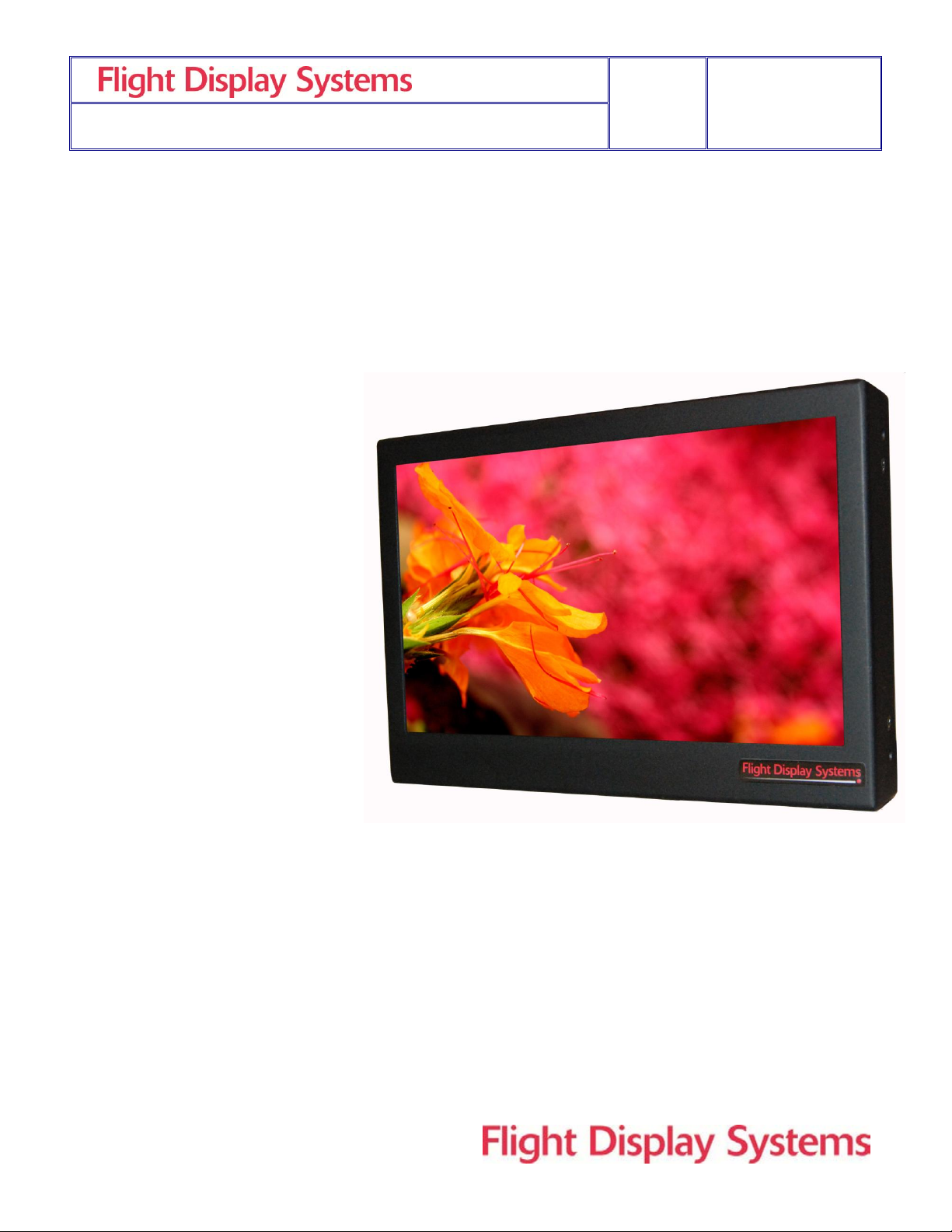
FD70CV-M
Installation and Operation Manual
7” Widescreen LCD
678-867-6717, or
www.FlightDisplay.com
Rev:
H
Revision Date:
06/19/2012
Page 2 of 14
MAN – FD70CV-M
FD70CV-M
7” Widescreen LCD
© 2006 Flight Display Systems. All Rights Reserved.
Flight Display Systems
1765 Grassland Parkway
Alpharetta, GA 30004
678-867-6717 Phone
678-867-6742 Fax
sales@flightdisplay.com
www.flightdisplay.com
For the most current copy of all product manuals, please visit our website at
www.flightdisplay.com
Rev:
H
Revision Date:
06/19/2012
Page 3 of 14
MAN – FD70CV-M
Table of Contents
General Information ......................................................................................................................4
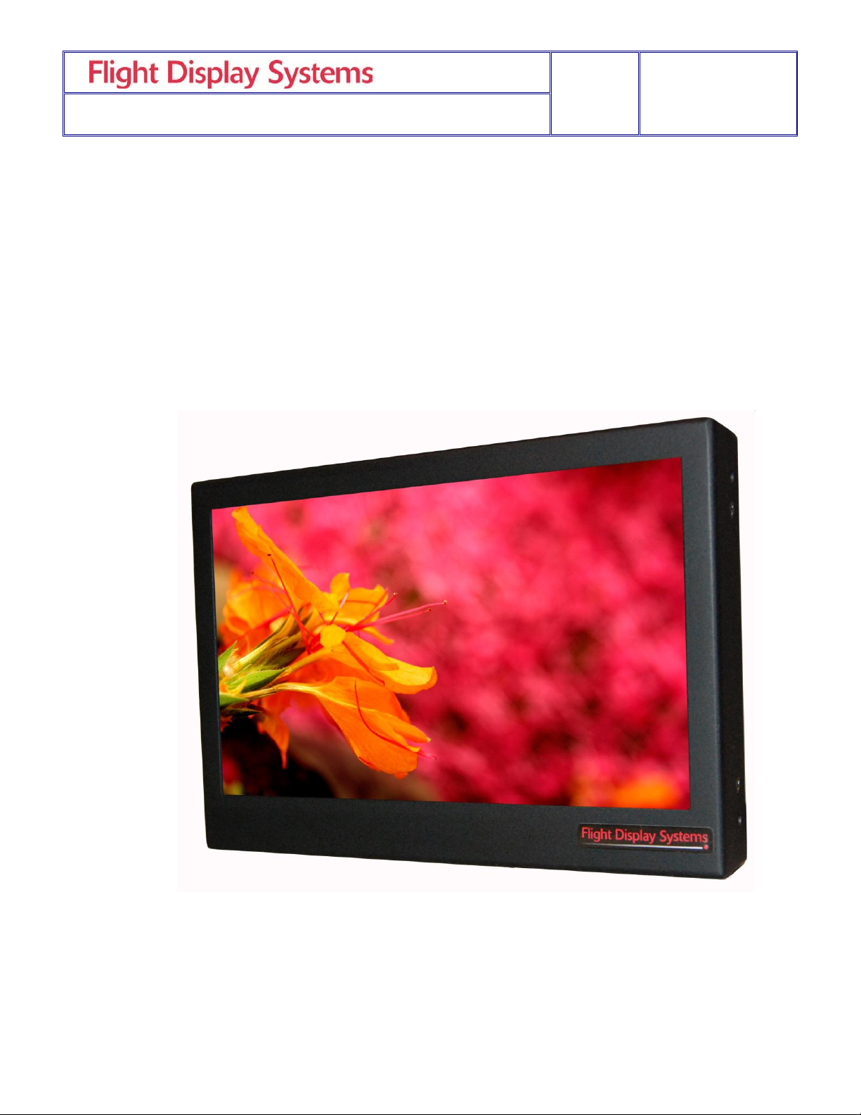
1. Front View ..........................................................................................................................4
Specifications ................................................................................................................................5
Installation Instructions .............................................................................................................5
1. Power ..................................................................................................................................6
Video Wiring Suggestions .........................................................................................................6
1. S-Video/Composite & Audio Wiring ............................................................................6
2. VGA Wiring .......................................................................................................................7
3. HDMI ..................................................................................................................................7
4. Power & Ground Wiring..................................................................................................8
5. Power/Video .....................................................................................................................8
Operations Instructions ..............................................................................................................9
1. Monitor Button Controls ..................................................................................................9
Technical Drawing.....................................................................................................................10
Troubleshooting .........................................................................................................................11
1. Video Noise ......................................................................................................................11
2. VGA Shadowing .............................................................................................................11
3. Snow or Sweeping Lines ................................................................................................11
4. No Power to Monitor, No Video Input ........................................................................11
5. Color Distortion ...............................................................................................................11
6. Remote Control Inoperable ...........................................................................................11
Technical Support ......................................................................................................................12
Instructions for Continued Airworthiness ...........................................................................12
Warranty ......................................................................................................................................13
Log of Revisions .........................................................................................................................14
Rev:
H
Revision Date:
06/19/2012
Page 4 of 14
MAN – FD70CV-M
General Information
The FD70CV-M is the latest version of our popular 7” Widescreen LCD. The all metal case
is designed for installation in light jets, turboprops and piston aircraft. This unit is ideal in
situations where bulkhead space forward and aft is very limited. This unit is a full function
7-inch LCD housed in a metal case that will fit on most aircraft. The metal case makes it
easy to mount directly to the bulkhead or build the units into the cabinet wall. Mounting
holes are easily accessible on both sides of the unit.
Front View
Rev:
H
Revision Date:
06/19/2012
Page 5 of 14
MAN – FD70CV-M
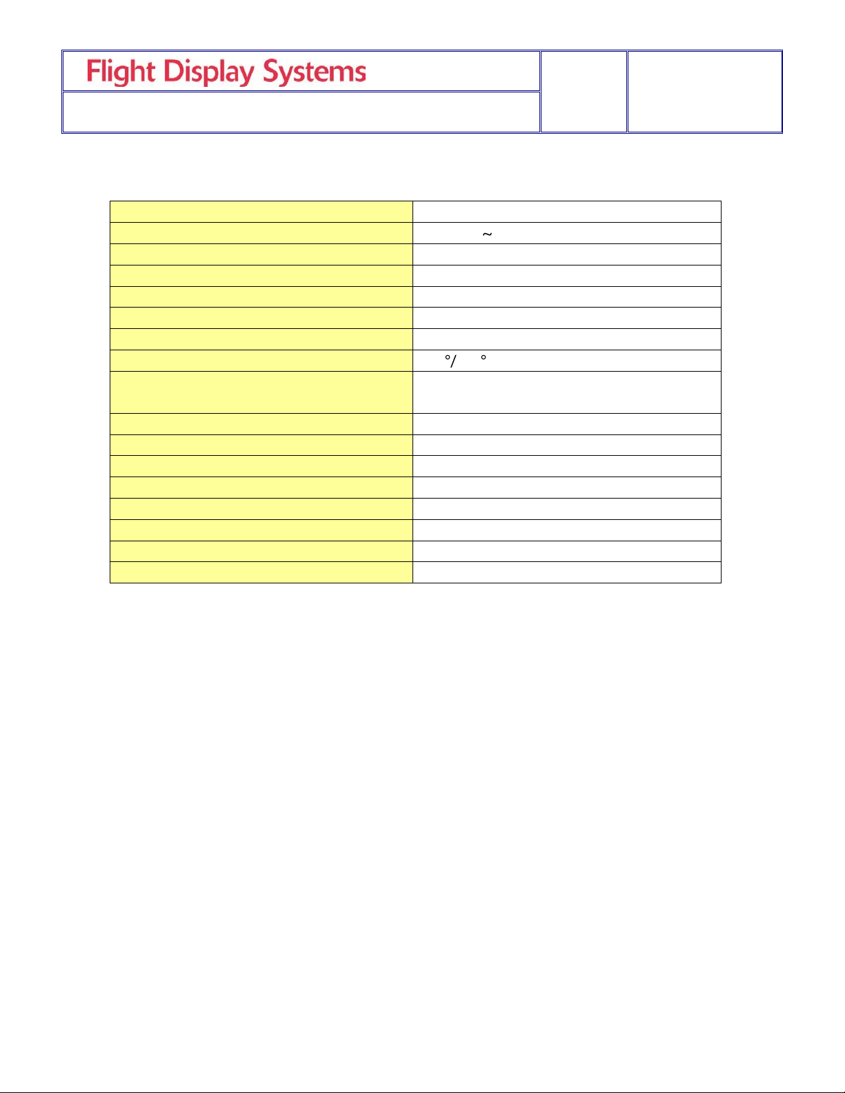
Display Type
7” TFT Color LCD
Supported Resolutions
640x480 1024x768
Display Brightness
450 cd/ m2
Contrast Ratio
500:1
Dimensions
6.80”(W) x 4.75”(H) x 1.20”(D)
LCD Dimension
6.00”(W) x 3.60”(H)
Weight
1 lb 5 oz
Viewing Angle
140 120
Power
12VDC @ .6 Amps
28VDC @ .3 Amps
Operating Temperature
0-50° C (32-122° F)
PC Video Input
VGA (Analog RGB 15 pin D-sub)
Standard Video Input
2 Composite Video
Video Type Supported
NTSC, PAL
Screen Control
On-Screen Display Menu
Remote Control
IR, included
Materials
Aluminum
DO-160 Testing
Section 21, Category B
Specifications
Installation Instructions
All cabin entertainment equipment, such as the FD70CV-M, should be installed on a nonessential bus and have a dedicated circuit breaker. It is a requirement that a switch be
installed in the cockpit so that the pilot can de-energize the entertainment system should it
become necessary.
The order in which you proceed is up to the installation center. We suggest that you first
look at the mounting plate prior to installing the LCD to make sure you have the proper
room and conditions in the aircraft to mount the display to the wall or bulkhead. Once it has
been determined that you have sufficient room and mounting locations for the FD70CV-M,
then it would be appropriate to start mounting the base to the frame. The unit can be
mounted to the bulkhead with fasteners which are located on the rear cover, or installer can
use “L” brackets and attach to the sides (2 located on each side of the display), from back
or sides using the 8-32 fastener. Length of the screw must not exceed .250” to the inside
of the screw. Screw length is dependent upon thickness of the “L” brackets. NOTE: Care
should be taken to ensure the unit is not installed in an area with poor ventilation, or
in an area with excessive heat.
 Loading...