

Flight Display Systems FD104CV Installation And Operation Manual
Document Number:
MAN – FD104CV
Rev:
E
Revision Date:
01/27/2011
Page 1 of 16
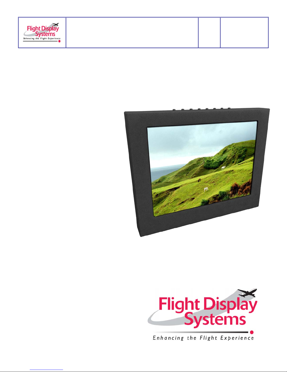
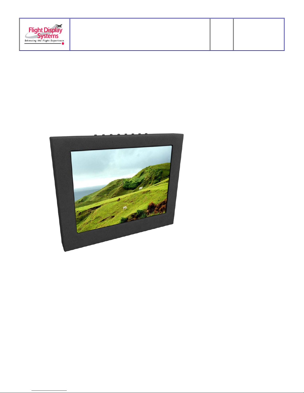
FD104CV
Installation and Operation Manual
10.4” LCD
TECHNICAL SUPPORT
678-867-6717, or
www.FlightDisplay.com

Document Number:
MAN – FD104CV
Rev:
E
Revision Date:
01/27/2011
Page 2 of 16
FD104CV
10.4” LCD
© 2006 Flight Display Systems. All Rights Reserved.
Flight Display Systems
1765 Grassland Parkway
Alpharetta, GA 30004
678-867-6717 Phone
678-867-6742 Fax
sales@flightdisplay.com
www.flightdisplay.com
For the most current copy of all product manuals, please visit our website at
www.flightdisplay.com

Document Number:
MAN – FD104CV
Rev:
E
Revision Date:
01/27/2011
Page 3 of 16
Table of Contents
General Information ......................................................................................................................4
1. Front View ..........................................................................................................................4
2. Additional Information ....................................................................................................4
Specifications ................................................................................................................................5
Installation Instructions .............................................................................................................5
1. Rear Connector Orientation ............................................................................................6
2. Power ..................................................................................................................................6
Wiring Instructions ......................................................................................................................7
1. Wiring Suggestions ...........................................................................................................7
2. S-Video/Composite and Audio Wiring ........................................................................7
3. VGA Wiring .......................................................................................................................8
4. Power & Ground Wiring .................................................................................................9
5. Power/Video ...................................................................................................................10
Operations Instructions ............................................................................................................11
1. Button Control .................................................................................................................11
Technical Drawing .....................................................................................................................12
Troubleshooting .........................................................................................................................13
1. Video Noise ......................................................................................................................13
2. VGA Shadowing .............................................................................................................13
3. Snow or Sweeping Lines ................................................................................................13
4. No power to monitor, No video inputs .......................................................................13
5. Color Distortion ...............................................................................................................13
6. Remote Control Inoperable ...........................................................................................13
Technical Support ......................................................................................................................14
Instructions for Continued Airworthiness ...........................................................................14
Warranty ......................................................................................................................................15
Log of Revisions .........................................................................................................................16
Document Number:
MAN – FD104CV
Rev:
E
Revision Date:
01/27/2011
Page 4 of 16
General Information
The FD104CV is a 10.4” LCD. Built with retrofit aircraft integration in mind, this display can
switch between three video input sources using buttons on the bezel or the infrared
Remote.
Front View
Additional Information
The FD104CV is made of all metal components. The LCD is protected with a .060” Lexan
lens. The purpose of this lens is to prevent scratching and reduce glare.
The 10.4” LCD utilizes a state of the art digital video decoding chipset for the analog video
input. The three video sources in order of picture quality are VGA (Computer Video, such
as a Moving Map), S-Video (High-quality DVD), and Composite Video (DVD, Camera, or
VCR). Both NTSC and PAL formats are auto-detected.
The FD104CV can also be connected to existing video switchers and can take a composite
video input from a selector interface box. In this case, multiple input sources can be
selected and displayed on the monitor.
Document Number:
MAN – FD104CV
Rev:
E
Revision Date:
01/27/2011
Page 5 of 16
Specifications
Display Type
10.4” TFT Color LCD
Display Color
262,144 Colors
Screen Resolution
1024x768 (1280x768 supported)
Brightness
700 cd/m2
Display Dimensions
8.24”(W) x 6.2” (H)
Weight
3 lbs 8 oz
Power
28V DC @ 1.0A
Video Inputs Supported
S-Video, Composite Video
Video Types Supported
NTSC/PAL
Screen Control
On Screen Display Menu
Mount Materials
Aluminum
DO-160 Testing
Section 21, Category B
Remote Control
IR, included
Installation Instructions
All cabin entertainment equipment, such as the FD104CV, should be installed on a nonessential bus and have a dedicated circuit breaker. It is a requirement that a switch be
installed in the cockpit so that the pilot can de-energize the entertainment system should it
become necessary.
Rear Connector Orientation – The rear connector of this monitor can be mounted
horizontally (connector perpendicular to rear of monitor) or vertically (connector
perpendicular to bottom of monitor) in order to give you the most convenient mounting
options. By default, this monitor's connector ships in the rear/horizontal position. Flight
Display Systems will ship the unit with the optional bottom/vertical mounting connector
configuration if specified at the time of order; contact your local sales representative for
assistance. It is possible to change the connector orientation at the time of installation.
For instructions on how to change the connector orientation please call Flight Display
Systems at +1 (678) 867-6717 and ask for Technical Support.
 Loading...