

FLIGHT DESIGN CTLS Series Maintenance And Inspection Procedures Manual
CTLS
LSA
SERIAL NUMBER:_______________
Maintenance and Inspection Procedures Manual
THIS DOCUMENT AND THE TECHNICAL DATA HEREON DISCLOSED ARE PROPRIETARY TO FLIGHT DESIGN AND SHALL
NOT BE USED, RELEASED, OR DISCLOSED IN WHOLE OR IN PART WITHOUT EXPRESS WRITTEN PERMISSION FROM
FLIGHT DESIGN
Maintenance and Inspection Procedures Manual
Type:
CT
Series:
REVISION STATUS
Rev Pages Date Chapter completed
1 All Jan 10, 2008 All Vasyl Sys
2
3
- System of pages numbering changed
- Formatting (page breaks) partially changed
All “or higher grade of certificate” added to
1-5 1.6 Equipment List updated
1-10–1-11 1.13 changed
1-12 1.15 “Owner’s operational” changed to “Service”
8-1 8 changed
8-2 8.5.2 changed
8-2 8.5.3 changed
8-3 – 8-4 8.5.10 – 8.5.16 added
8-5 8.6 changed
1
1-1 1 Updated with Warning
1-2 1.3 Warning deleted
1-8 1.9 Operating speeds and limits updated
2-11–2-12 2.9 updated with “Lubricate rod end bearings”
3-1 3 page numbers corrected in the table
3-32–3-40 3.3.2 updated
5-2 5.1 updated
8-3 8.5.9 C9997199F Switch panel EK 10228 deleted
8-4
All Number of document changed
1 App. I changed to App. V
17 App. I changed to App. V
1-1 1 updated
1-1 1.2 added contact
1-6 1.6 text added
1-9 1.9 “Engine specification” deleted
1-9 1.10 “Minimum single pilot weight” deleted
3-10 3.1.2.6 changed
8-3 8.5.6 Vertical Speed Indicator (Variometer)
9-1 9. deleted incorrect drawing number
11-1 11.1 updated
2-4 2.3 – 2.10 updated
3-11-3-21
3-1 – 10-5 Allocation of Level of Maintenance and Level of
1-1 Address of Flight Design is changed 4
AІV-1-AІV-14
Apr 01, 2008
“Repairman, Light Sport Aircraft-Maintenance
(RLSA-M).”
App. 1 updated
Sep 14, 2008
8.5.10 Garmin SL30 added
8.5.11 changed
8.5.13 changed
deleted
3.2-3.2.1.9 “Stabilizer” moved to 3.4.4.
Certification detailed and adapted. Requirements
for Flight Design Training reviewed. Linguistic
clarifying corrections included throughout the
whole procedures.
02 Jan 2009
Added Appendix IV MATCO Brake System
CTLS
LSA
Page: ii
Vasyl Sys
Vasyl Sys
Vlada Luzhnykh
O. Reinhardt
S. Pilipenko
AF 04800001 Revision No. 4 Date: 02 Jan 2009
Maintenance and Inspection Procedures Manual
Type:
LIST OF EFFECTIVE PAGES
CHAPTER CHAPTER CHAPTER CHAPTER
1
2
3
4
PAGES PAGES PAGES PAGES
REV
1-1
1-2
1-3
1-4
1-5
1-6
1-7
1-8
1-9
1-10
1-11
1-12
1-13
2-1
2-2
2-3
3-1
3-2
3-3
3-4
3-5
3-6
3-7
3-8
3-9
3-10
3-11
3-12
4-1
4-2
4-3
4-4
4-5
4-6
4-7
4-8
4-9
4-10
4-11
4-12
4-13
4-14
4-15
4-16
4
3
3
3
3
3
3
3
3
3
3
3
3
3
3
3
3
3
3
3
3
3
3
3
3
3
3
3
3
3
3
3
3
3
3
3
3
3
3
3
3
3
3
3
CT
4
(cont.)
Series:
REV
4-17
4-18
4-19
4-20
4-21
4-22
4-23
4-24
4-25
4-26
4-27
4-28
4-29
4-30
4-31
4-32
4-33
4-34
4-35
4-36
4-37
4-38
4-39
4-40
4-41
4-42
4-43
4-44
4-45
4-46
4-47
4-48
4-49
4-50
4-51
4-52
4-53
4-54
4-55
4-56
4-57
4-58
4-59
4-60
3
3
3
3
3
3
3
3
3
3
3
3
3
3
3
3
3
3
3
3
3
3
3
3
3
3
3
3
3
3
3
3
3
3
3
3
3
3
3
3
3
3
3
3
4
(cont.)
5
6
7
8
CTLS
REV
5-1
5-2
5-3
5-4
6-1
6-2
6-3
6-4
6-5
6-6
6-7
6-8
6-9
7-1
8-1
8-2
8-3
8-4
3
3
3
3
3
3
3
3
3
3
3
3
3
3
3
3
3
3
3
3
3
3
3
3
3
3
3
3
3
3
3
3
3
3
3
3
3
3
3
3
3
3
3
3
4-61
4-62
4-63
4-64
4-65
4-66
4-67
4-68
4-69
4-70
4-71
4-72
4-73
4-74
4-75
4-76
4-77
4-78
4-79
4-80
4-81
4-82
4-83
4-84
4-85
4-86
LSA
8
(cont.)
9
10
App. I
App. II
App. III
App. IV AIV-1-
Page: iii
REV
8-5
8-6
8-7
8-8
8-9
9-1
9-2
9-3
9-4
9-5
10-1
10-2
10-3
10-4
10-5
AI-1
AI-2
AI-3
AII-1
AII-2
AIII-1
AIV-14
3
3
3
3
3
3
3
3
3
3
3
3
3
3
3
3
3
3
3
3
3
4
AF 04800001 Revision No. 4 Date: 02 Jan 2009

Maintenance and Inspection Procedures Manual
Type:
CT
Series:
TABLE OF CONTENTS
General............................................................................................................................................ 1-1
1
1.1 Manufacturer............................................................................................................................. 1-1
1.2 Contact in USA.......................................................................................................................... 1-1
1.3 Care and cleaning of your CT................................................................................................... 1-2
1.4 Views, dimensions .................................................................................................................... 1-3
1.5 Construction Materials .............................................................................................................. 1-5
1.6 Equipment List .......................................................................................................................... 1-6
1.7 Source to Purchase Parts......................................................................................................... 1-7
1.8 List of Disposable Replacement Parts...................................................................................... 1-7
1.9 Weight and Balance Information...............................................................................................1-8
1.10 Tire Inflation Pressure.............................................................................................................1-10
1.11 Approved Fluids and Capacities............................................................................................. 1-10
1.12 Recommended Fastener Torque Values and Bolts Installation ............................................. 1-11
1.13 General Safety Information..................................................................................................... 1-12
1.14 Instructions for Reporting Possible Safety of Flight Concerns Found During Inspection /
Maintenance............................................................................................................................ 1-13
2 Minimum Levels of Certification:...................................................................................................... 2-1
2.1 General ..................................................................................................................................... 2-1
2.2 Levels of certification................................................................................................................. 2-1
2.3 Required certification level for maintenance procedures..........................................................2-2
3 Aircraft Inspections.......................................................................................................................... 3-1
3.1 Aircraft Records ........................................................................................................................ 3-2
3.2 Run-up ...................................................................................................................................... 3-3
3.3 Post-Run-up.............................................................................................................................. 3-4
3.4 Propulsion System.................................................................................................................... 3-5
3.5 Fuselage ................................................................................................................................... 3-6
3.6 Wings ........................................................................................................................................ 3-7
3.7 Empennage...............................................................................................................................3-8
3.8 Landing Gear ............................................................................................................................ 3-9
3.9 Cabin and Baggage Compartment ......................................................................................... 3-10
3.10 Inspection Completion............................................................................................................. 3-12
4 Structures ........................................................................................................................................ 4-1
4.1 Wing.......................................................................................................................................... 4-1
4.1.1 Wing Structure..................................................................................................................... 4-1
4.1.2 Wing Installation and Removal............................................................................................ 4-2
4.1.2.1 Tools Required............................................................................................................ 4-2
4.1.2.2 Parts and Materials Required ..................................................................................... 4-2
4.1.2.3 Type of Maintenance .................................................................................................. 4-2
4.1.2.4 Minimum Level of Certification.................................................................................... 4-2
4.1.2.5 Wing Installation.......................................................................................................... 4-2
4.1.2.6 Wing Removal............................................................................................................. 4-9
4.1.2.7 Verification Required................................................................................................... 4-9
4.2 Landing Gear .......................................................................................................................... 4-10
4.2.1 Nose Landing Gear............................................................................................................ 4-10
4.2.1.1 Tools Required.......................................................................................................... 4-10
4.2.1.2 Materials Required....................................................................................................4-10
4.2.1.3 General ..................................................................................................................... 4-10
4.2.1.4 Inspections................................................................................................................ 4-11
4.2.1.4.1 Type of Maintenance........................................................................................... 4-11
4.2.1.4.2 Minimum Level of Certification ............................................................................ 4-11
4.2.1.4.3 Visual Inspection ................................................................................................. 4-11
4.2.1.4.4 Shock Absorber Inspection.................................................................................. 4-12
4.2.1.4.5 Fork Inspection.................................................................................................... 4-12
4.2.1.4.6 Nose Wheel Inspection........................................................................................ 4-12
4.2.1.5 Nose Gear Removal (Replacement)......................................................................... 4-13
4.2.1.5.1 Type of Maintenance........................................................................................... 4-13
CTLS
LSA
Page: iv
AF 04800001 Revision No. 3 Date: 14 Sep 2008

Maintenance and Inspection Procedures Manual
Type:
CT
4.2.1.5.2
4.2.1.5.3 Fork Removal ...................................................................................................... 4-13
4.2.1.5.4 Before Installation................................................................................................4-14
4.2.1.5.5 Fork Installation ................................................................................................... 4-14
4.2.1.5.6 Fork Replacement ............................................................................................... 4-15
4.2.1.5.7 Shock Absorber................................................................................................... 4-15
4.2.1.6 Nose Wheel...............................................................................................................4-16
4.2.1.6.1 Type of Maintenance........................................................................................... 4-16
4.2.1.6.2 Minimum Level of Certification ............................................................................ 4-16
4.2.1.6.3 Nose Wheel Removal and Installation ................................................................ 4-16
4.2.2 Main Landing Gear............................................................................................................ 4-18
4.2.2.1 Tools Required.......................................................................................................... 4-18
4.2.2.2 Materials Required....................................................................................................4-18
4.2.2.3 General ..................................................................................................................... 4-19
4.2.2.4 Inspection..................................................................................................................4-19
4.2.2.4.1 Type of Maintenance........................................................................................... 4-19
4.2.2.4.2 Minimum Level of Certification ............................................................................ 4-19
4.2.2.4.3 Visual inspection.................................................................................................. 4-19
4.2.2.4.4 Wheel Inspection................................................................................................. 4-19
4.2.2.5 Main Wheel Fairing Removal (Replacement)........................................................... 4-19
4.2.2.5.1 Type of Maintenance........................................................................................... 4-19
4.2.2.5.2 Minimum Level of Certification ............................................................................ 4-19
4.2.2.5.3 Procedure............................................................................................................ 4-20
4.2.2.6 Main Wheel Removal and Installation ...................................................................... 4-21
4.2.2.6.1 Type of Maintenance........................................................................................... 4-21
4.2.2.6.2 Minimum Level of Certification ............................................................................ 4-21
4.2.2.6.3 Wheel Brake Line Disconnecting ........................................................................ 4-21
4.2.2.6.4 Main Wheel Removal .......................................................................................... 4-21
4.2.2.6.5 Before Installation................................................................................................4-22
4.2.2.6.6 Main Wheel Installation ....................................................................................... 4-22
4.2.2.7 Removal (Replacement) of Main Strut Fairing.......................................................... 4-23
4.2.2.7.1 Type of Maintenance........................................................................................... 4-23
4.2.2.7.2 Minimum Level of Certification ............................................................................ 4-23
4.2.2.8 Main Gear Struts Removal and Installation.............................................................. 4-24
4.2.2.8.1 Type of Maintenance........................................................................................... 4-24
4.2.2.8.2 Minimum Level of Certification ............................................................................ 4-24
4.2.2.8.3 Procedure............................................................................................................ 4-24
4.2.2.9 Wheel Inspection and Maintenance.......................................................................... 4-25
4.2.2.9.1 Type of Maintenance........................................................................................... 4-25
4.2.2.9.2 Minimum Level of Certification ............................................................................ 4-25
4.2.2.9.3 Procedure............................................................................................................ 4-25
4.2.3 Brake System ....................................................................................................................4-27
4.2.3.1 Tools Required.......................................................................................................... 4-27
4.2.3.2 Materials Required....................................................................................................4-27
4.2.3.3 Inspection..................................................................................................................4-27
4.2.3.3.1 Type of Maintenance........................................................................................... 4-27
4.2.3.3.2 Minimum Level of Certification ............................................................................ 4-27
4.2.3.3.3 General................................................................................................................ 4-27
4.2.3.3.4 Inspection of Wheel Brakes.................................................................................4-28
4.2.3.3.5 Inspection of Brake Controls ............................................................................... 4-29
4.2.3.4 Filling Brake System with Fluid.................................................................................4-31
4.2.3.4.1 Type of Maintenance........................................................................................... 4-31
4.2.3.4.2 Minimum Level of Certification ............................................................................ 4-31
4.2.3.4.3 Procedure............................................................................................................ 4-31
4.2.3.5 Brake Pads Replacement......................................................................................... 4-32
4.2.3.5.1 Type of Maintenance........................................................................................... 4-32
4.2.3.5.2 Minimum Level of Certification ............................................................................ 4-32
4.2.3.5.3 Procedure............................................................................................................ 4-32
4.3 Flight Controls......................................................................................................................... 4-33
Minimum Level of Certification ............................................................................ 4-13
Series:
CTLS
LSA
Page: v
AF 04800001 Revision No. 3 Date: 14 Sep 2008

Maintenance and Inspection Procedures Manual
Type:
CT
Aileron................................................................................................................................ 4-33
4.3.1
4.3.1.1 New design of aileron control system....................................................................... 4-34
4.3.1.2 Tools Required.......................................................................................................... 4-35
4.3.1.3 Materials Required....................................................................................................4-35
4.3.1.4 General ..................................................................................................................... 4-35
4.3.1.5 Inspection..................................................................................................................4-35
4.3.1.5.1 Type of Maintenance........................................................................................... 4-35
4.3.1.5.2 Minimum Level of Certification ............................................................................ 4-35
4.3.1.5.3 Bracket Inspection............................................................................................... 4-36
4.3.1.5.4 Wing bracket bearings inspection ....................................................................... 4-36
4.3.1.5.5 Rods / Bellcranks inspection ............................................................................... 4-37
4.3.1.6 Aileron Installation..................................................................................................... 4-37
4.3.1.6.1 Type of Maintenance........................................................................................... 4-37
4.3.1.6.2 Minimum Level of Certification ............................................................................ 4-37
4.3.1.7 Aileron Adjustment....................................................................................................4-42
4.3.1.7.1 Type of Maintenance........................................................................................... 4-42
4.3.1.7.2 Minimum Level of Certification ............................................................................ 4-42
4.3.1.7.3 Rigging Aileron “Zero” Position............................................................................ 4-42
4.3.1.7.4 Aileron Deflection Adjustment ............................................................................. 4-44
4.3.1.7.5 Measuring Aileron Deflection............................................................................... 4-45
4.3.1.8 Verification of Aileron Installation and Adjustment ................................................... 4-47
4.3.2 Flaps.................................................................................................................................. 4-48
4.3.2.1 Tools Required.......................................................................................................... 4-48
4.3.2.2 Materials Required....................................................................................................4-48
4.3.2.3 General ..................................................................................................................... 4-49
4.3.2.4 Inspection..................................................................................................................4-49
4.3.2.4.1 Type of Maintenance........................................................................................... 4-49
4.3.2.4.2 Minimum Level of Certification ............................................................................ 4-49
4.3.2.4.3 Bracket Inspection............................................................................................... 4-49
4.3.2.4.4 Wing bracket bearings inspection ....................................................................... 4-50
4.3.2.4.5 Rods / Bellcranks inspection ............................................................................... 4-51
4.3.2.5 Flap Installation.........................................................................................................4-51
4.3.2.5.1 Type of Maintenance........................................................................................... 4-51
4.3.2.5.2 Minimum Level of Certification ............................................................................ 4-51
4.3.2.5.3 Procedure............................................................................................................ 4-51
4.3.2.6 Flap Adjustment........................................................................................................ 4-53
4.3.2.6.1 Type of Maintenance........................................................................................... 4-53
4.3.2.6.2 Minimum Level of Certification ............................................................................ 4-53
4.3.2.6.3 Rigging “Zero” Position of the Flaps....................................................................4-53
4.3.2.6.4 Flap Deflection Adjustment.................................................................................. 4-54
4.3.2.6.5 Measuring Flap Deflection...................................................................................4-56
4.3.2.7 Inspection of Flap Control Microswitches.................................................................4-59
4.3.2.7.1 Type of Maintenance........................................................................................... 4-59
4.3.2.7.2 Minimum Level of Certification ............................................................................ 4-59
4.3.2.7.3 Procedure............................................................................................................ 4-59
4.3.3 Rudder............................................................................................................................... 4-60
4.3.3.1 Tools Required.......................................................................................................... 4-60
4.3.3.2 Materials Required....................................................................................................4-60
4.3.3.3 Rudder Installation and Removal.............................................................................. 4-60
4.3.3.3.1 Type of Maintenance........................................................................................... 4-60
4.3.3.3.2 Minimum Level of Certification Required............................................................. 4-60
4.3.3.3.3 Procedure............................................................................................................ 4-60
4.3.3.4 Rudder Deflection Adjustment.................................................................................. 4-63
4.3.3.4.1 Type of Maintenance........................................................................................... 4-63
4.3.3.4.2 Minimum Level of Certification ............................................................................ 4-63
4.3.3.4.3 Measuring Rudder Deflection..............................................................................4-64
4.3.3.4.4 Rigging Rudder Neutral Position......................................................................... 4-66
4.3.3.4.5 Adjusting of Control Cable Tension.....................................................................4-67
4.3.3.4.6 Fine Adjustment................................................................................................... 4-68
Series:
CTLS
LSA
Page: vi
AF 04800001 Revision No. 3 Date: 14 Sep 2008

Maintenance and Inspection Procedures Manual
Type:
CT
4.3.3.4.7
4.3.3.5 Verification of Rudder Installation and Adjustment...................................................4-69
4.3.4 Stabilator............................................................................................................................ 4-70
4.3.4.1 Tools Required.......................................................................................................... 4-71
4.3.4.2 Parts and Materials Required ................................................................................... 4-71
4.3.4.3 General ..................................................................................................................... 4-71
4.3.4.4 Stabilator Installation and Removal.......................................................................... 4-71
4.3.4.4.1 Type of Maintenance........................................................................................... 4-71
4.3.4.4.2 Minimum Level of Certification ............................................................................ 4-71
4.3.4.4.3 Procedure............................................................................................................ 4-71
4.3.4.5 Stabilator Adjustment................................................................................................4-77
4.3.4.5.1 Type of Maintenance........................................................................................... 4-77
4.3.4.5.2 Minimum Level of Certification ............................................................................ 4-77
4.3.4.5.3 Measuring Stabilator Deflection........................................................................... 4-78
4.3.4.5.4 Measuring of Trim Tab Deflection and Adjustment............................................. 4-81
4.3.4.6 Balancing of the Stabilator Balancer......................................................................... 4-83
4.3.4.6.1 Type of Maintenance........................................................................................... 4-83
4.3.4.6.2 Minimum Level of Certification ............................................................................ 4-83
4.3.4.6.3 Procedure............................................................................................................ 4-83
4.3.4.7 Verification of Stabilator Installation and Adjustment ............................................... 4-84
4.4 Structural Repair..................................................................................................................... 4-85
4.4.1 Type of Maintenance......................................................................................................... 4-85
4.4.2 Minimum Level of Certification .......................................................................................... 4-85
4.4.3 Repair Procedures.............................................................................................................4-85
4.5 Painting and Coating............................................................................................................... 4-85
4.5.1 Tools needed to accomplish the task................................................................................ 4-85
4.5.2 The parts needed to perform the task ............................................................................... 4-85
4.5.3 Type of Maintenance......................................................................................................... 4-85
4.5.4 Minimum Level of Certification .......................................................................................... 4-85
4.5.5 Puttying..............................................................................................................................4-85
4.5.6 Priming............................................................................................................................... 4-86
4.5.7 Painting..............................................................................................................................4-86
4.5.8 Polishing ............................................................................................................................ 4-86
4.5.9 Method of Verification........................................................................................................ 4-86
5 Engine.............................................................................................................................................. 5-1
5.1 Engine Systems and Accessories............................................................................................. 5-1
5.2 Rotax 912ULS Engine............................................................................................................... 5-1
5.3 Carb Heat Control..................................................................................................................... 5-2
5.3.1 Tools Required .................................................................................................................... 5-2
5.3.2 Materials Required............................................................................................................... 5-2
5.3.3 Type of Maintenance........................................................................................................... 5-2
5.3.4 Minimum Level of Certification ............................................................................................ 5-2
5.3.5 General................................................................................................................................ 5-2
5.3.6 Inspection of Carburetor Heater Control.............................................................................. 5-2
6 Fuel System..................................................................................................................................... 6-1
6.1 General ..................................................................................................................................... 6-1
6.2 Tools Required.......................................................................................................................... 6-3
6.3 Materials Required.................................................................................................................... 6-3
6.4 General System Inspection.......................................................................................................6-3
6.4.1 Type of Maintenance........................................................................................................... 6-3
6.4.2 Minimum Level of Certification ............................................................................................ 6-3
6.4.3 Procedure ............................................................................................................................6-3
6.5 Fuel Flow Check ....................................................................................................................... 6-4
6.5.1 Type of Maintenance........................................................................................................... 6-4
6.5.2 Minimum Level of Certification ............................................................................................ 6-4
6.5.3 Checking of Fuel Flow Rate ................................................................................................ 6-4
6.5.4 Simulation of In-Flight Engine Restart................................................................................. 6-4
6.6 Intake Filter / Side Access Panel..............................................................................................6-6
6.6.1 Type of Maintenance........................................................................................................... 6-6
Coarse Adjustment.............................................................................................. 4-68
Series:
CTLS
LSA
Page: vii
AF 04800001 Revision No. 3 Date: 14 Sep 2008

Maintenance and Inspection Procedures Manual
Type:
CT
Minimum Level of Certification ............................................................................................ 6-6
6.6.2
6.6.3 Procedure ............................................................................................................................6-6
6.7 Fuel Filter..................................................................................................................................6-8
6.7.1 Type of Maintenance........................................................................................................... 6-8
6.7.2 Minimum Level of Certification ............................................................................................ 6-8
6.7.3 Procedure ............................................................................................................................6-8
6.8 Gascolator.................................................................................................................................6-9
6.8.1 Type of Maintenance........................................................................................................... 6-9
6.8.2 Minimum Level of Certification ............................................................................................ 6-9
6.8.3 Procedure ............................................................................................................................6-9
7 Propeller .......................................................................................................................................... 7-1
7.1 Type of Maintenance.................................................................................................................7-1
7.2 Minimum Level of Certification..................................................................................................7-1
7.3 Propeller Maintenance Procedures........................................................................................... 7-1
8 Utility Systems................................................................................................................................. 8-1
8.1 Tools Required.......................................................................................................................... 8-1
8.2 Materials Required.................................................................................................................... 8-1
8.3 Cabin Heat System................................................................................................................... 8-1
8.3.1.1 Type of Maintenance .................................................................................................. 8-1
8.3.1.2 Minimum Level of Certification.................................................................................... 8-1
8.3.1.3 Procedure.................................................................................................................... 8-1
9 Instruments and Avionics ................................................................................................................ 9-1
9.1 Tools Required.......................................................................................................................... 9-1
9.2 Parts Required.......................................................................................................................... 9-1
9.3 Instrument Maintenance............................................................................................................ 9-1
9.3.1 Type of Maintenance........................................................................................................... 9-1
9.3.2 Minimum Level of Certification ............................................................................................ 9-1
9.3.3 General................................................................................................................................ 9-1
9.3.4 Glass Cockpit Dynon EFIS 100........................................................................................... 9-1
9.3.5 Glass Cockpit Dynon EMS D120......................................................................................... 9-1
9.3.6 Analog Airspeed Indicator ................................................................................................... 9-2
9.3.7 Analog One Pointer Altimeter.............................................................................................. 9-2
9.3.8 Magnetic Compass with Deviation Table ............................................................................ 9-2
9.3.9 Flap position indicator.......................................................................................................... 9-2
9.3.10 Hobbs Hour Meter........................................................................................................... 9-2
9.3.11 Radio Garmin SL30 with VOR functionality.................................................................... 9-2
9.3.12 Radio Garmin SL40 installed with antenna.....................................................................9-2
9.3.13 Transponder Garmin installation..................................................................................... 9-3
9.3.14 Altitude Encoder ACK A30 (Classic) or Dynon (Advanced)............................................ 9-3
9.3.15 GPS Garmin 496............................................................................................................. 9-3
9.3.16 ELT Ameriking AK450..................................................................................................... 9-3
9.3.17 Intercom PM 3000 A with aux music input and connection to GPS Audio ..................... 9-3
9.4 Inspection of Pitot & Static Port ................................................................................................ 9-4
9.4.1 Type of Maintenance........................................................................................................... 9-4
9.4.2 Minimum Level of Certification ............................................................................................ 9-4
9.4.3 Procedure ............................................................................................................................9-4
9.5 Special Equipment.................................................................................................................... 9-5
10 Electrical System........................................................................................................................... 10-1
10.1 Tools Required........................................................................................................................ 10-1
10.2 Materials Required.................................................................................................................. 10-1
10.3 General ................................................................................................................................... 10-1
10.3.1 Inspection...................................................................................................................... 10-5
10.3.1.1 Type of Maintenance............................................................................................ 10-5
10.3.1.2 Minimum Level of Certification ............................................................................. 10-5
10.3.1.3 Procedure............................................................................................................. 10-5
10.4 Battery Replacement............................................................................................................... 10-5
10.4.1 Type of Maintenance..................................................................................................... 10-5
10.4.2 Minimum Level of Certification...................................................................................... 10-5
10.4.3 Procedure......................................................................................................................10-5
Series:
CTLS
LSA
Page: viii
AF 04800001 Revision No. 3 Date: 14 Sep 2008

Maintenance and Inspection Procedures Manual
Type:
CT
Appendix I . Template for Trim Tab Deflection Angles Measurement ..........................................................1
Appendix II. Adjustment report......................................................................................................................1
Appendix III . Service Difficulty Report Form ................................................................................................1
Appendix IV . MATCO Brake System...........................................................................................................1
Series:
CTLS
LSA
Page: ix
AF 04800001 Revision No. 4 Date: 02 Jan 2009
Maintenance and Inspection Procedures Manual
Type:
CT
Series:
CTLS
LSA
Page: 1-1
1 General
This maintenance and inspection procedures manual provides all standard maintenance and inspection
procedures needed to keep the aircraft airworthy. This manual also states the certification requirements
for the persons performing each task. Maintenance tasks exceeding the scope of this manual are
possible but require prior coordination with and approval by the manufacturer.
The Flight Design CTLS is a three-axis control, high-wing, and two seats light sport aircraft of normal
scheme with a cruciform tail. The primary structures are made of carbon fiber reinforced plastic. The
aircraft is equipped with an all-moving stabilator with a trim tab and tricycle landing gear with a steerable
nose-wheel.
Federal rules require minimum certification levels of the mechanics perfoming individual maintenance
tasks on an S-LSA aircraft to be defined by the airframe manufacturer. Refer to chapter 2 for the definition
of the levels of certification applied throutghout this manual. On each individual task you will find the
allocation of level of certification.
WARNING: Use only alkali-free products when cleaning your composite aircraft. For
more information, refer to chapter 1.3 Care and cleaning of your CT.
1.1 Manufacturer
Flight Design GmbH
Sielminger Str. 51
D – 70771 L.-Echterdingen
Germany
1.2 Contact in USA
Flight Design USA
P.O. Box 325
South Woodstock, CT. 06267
860-963-7272
airworthiness@flightdesignUSA.com
AF 04800001 Revision No. 4 Date: 02 Jan 2009
Maintenance and Inspection Procedures Manual
Type:
CT
Series:
CTLS
LSA
Page: 1-2
1.3 Care and cleaning of your CT
Care must be taken when cleaning modern aircraft built with composite materials. Many products have
been developed to clean a specific type of material and may be unsuitable or even damaging to others.
Using the wrong product may damage your aircraft or its structures. Affected parts may be plainly visible
or may be hidden from view. The type of damage can vary from the simply unsightly to the outright
dangerous. You must always read the instructions for your cleaning products before using them. If you
should have any questions about a product’s suitability please contact your local dealer.
Each structure has its own cleaning requirements.
The basic airframe and wing structure
Composite aircraft are typically constructed of a sandwich of a structural material (Fiberglass-Carbon
Fiber or Kevlar) over a foam core.
The Flight Design CTLS is made up of a Carbon fiber-foam-Carbon fiber and Kevlar laminate sandwich
which is filled with polyester filler, sanded and painted with two-part urethane paint. The foam core of the
wings is partially Rohacell foam which was chosen for its stiffness and resistance to fuel. The fuselage
core is Airex foam which allows the contours for the CTLS fuselage.
The Rohacell foam, while highly resistant to fuel, is not resistant to strong Alkali cleaners or even water
with very high alkali content. Therefore Flight Design requires that the cleaners used on the CTLS be PH
neutral. Cleaners, such as Fantastik®, Formula 409®, Carbonex® and Castrol Super Clean®, which are
otherwise good Alkali cleaning products, should not be used on the CTLS.
The use of this category cleaner can dissolve the foam core of the sandwich leaving a dented looking
area that must be repaired and re-painted. Please note that the wing spars of the CTLS are sealed in
epoxy and fiberglass and cannot
The windshield and side windows
The windows of the CTLS are tinted, heat molded acrylic (also known as Plexiglas®). While durable, they
must be carefully cleaned to avoid scratching the surface. Never use an abrasive pad, abrasive pastes or
even dirty rags when cleaning the window surfaces. Always flush the window surface with water to
remove as much dust and dirt before using an aircraft window specific cleaner or a plastic cleaner
approved for cleaning acrylic windshields.
When polishing the windshield or side windows never polish in a circular motion, this creates a halo affect
when looking into the sun. Always use horizontal or vertical pattern.
The engine and engine compartment
The Rotax 912 maintenance manual recommends the use of a commercially available cold cleaning
agent. Some citrus based products have been found to be suitable. However, always read the
instructions for any product to be used, keeping in mind that it must be compatible with both the engine
components and the airframe structures.
be damaged in this manner.
AF 04800001 Revision No. 3 Date: 14 Sep 2008

Maintenance and Inspection Procedures Manual
Type:
CT
1.4 Views, dimensions
Series:
CTLS
LSA
Page: 1-3
AF 04800001 Revision No. 3 Date: 14 Sep 2008
Maintenance and Inspection Procedures Manual
Type:
CT
Series:
Geometry
Max. length 6604 mm 21 ft 8 in
Max. height 2342 mm 7 ft 8 in
Wing span 8594 mm 28 ft 2 in
Areas
Wing 9.98 m
Stabilator 1.60 m
Vertical tail 1.41 m
Aspect ratios
Wing 7,29
Stabilator 3,38
CTLS
2
2
2
LSA
Page: 1-4
107.43 sq ft
17.20 sq ft
15.16 sq ft
AF 04800001 Revision No. 3 Date: 14 Sep 2008

Maintenance and Inspection Procedures Manual
Type:
CT
Series:
CTLS
LSA
Page: 1-5
1.5 Construction Materials
The airframe is made of high-quality composite materials which permit excellent aerodynamic
characteristics to be achieved at an efficient structural mass. Due to the strict mass regulations for ultralight aircraft, re-inforced carbon and aramide fiber materials predominate.
Due to the complex nature of composite materials and the necessary knowledge in the lay-up of a
specific structure, repair work on the composite airframe may only be undertaken by a qualified facility.
For this reason, only general information about the materials used is given in this handbook. Should the
aircraft structure be damaged, detailed information should be requested from the manufacturer.
Carbon, aramide, glass fiber: various qualities
Lange & Ritter, Gerlingen
Resin and hardener: Larit L 285
Lange & Ritter, Gerlingen
Core material: Rohacell, Airex various qualities
Lange & Ritter, Gerlingen
Screws and bolts: unless otherwise stated, class 8.8 zinc-plated or
stainless steel, according to DIN standard
AF 04800001 Revision No. 3 Date: 14 Sep 2008

Maintenance and Inspection Procedures Manual
Type:
CT
Series:
CTLS
LSA
Page: 1-6
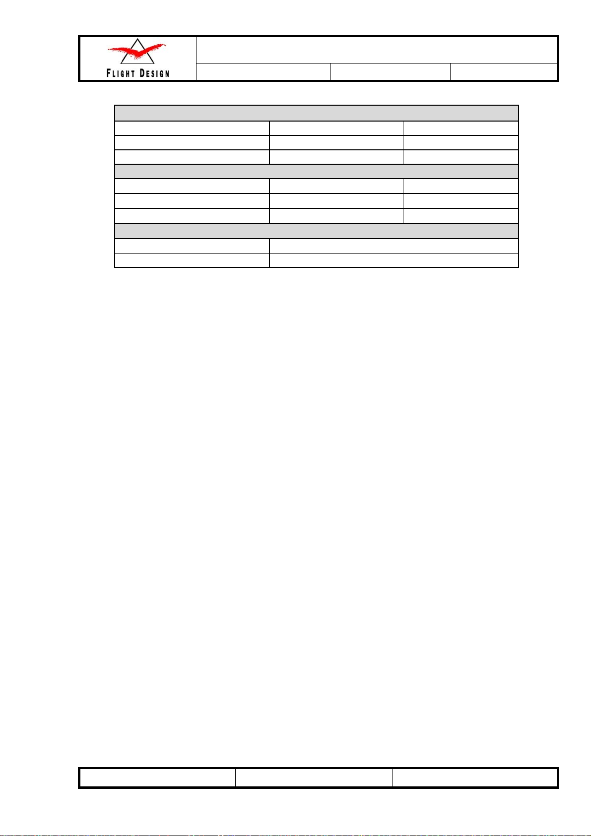
1.6 Equipment List
Each aircraft is delivered with an initial equipment list as part of this handbook. A new equipment list must
be compiled and added to aircraft logbook and to this manual when there is any change to the equipment.
The owner of the aircraft is responsible for ensuring that the equipment list is current.
The equipment list includes options which are not certified in all the countries in which the CTLS may be
operated. It is the responsibility of the owner to ensure that national regulations are followed, for example
with respect to the ballistic recovery system and the autopilot.
The equipment list is a summary of the aircraft at the time of an annual inspection or weighing. It is
mandatory to record the installation and/or removal of instruments in the aircraft logbook.
Note: Sample weight and balance sheet only; not valid for the actual aircraft.
AF 04800001 Revision No. 3 Date: 14 Sep 2008
.
Maintenance and Inspection Procedures Manual
Type:
CT
Series:
CTLS
LSA
Page: 1-7
1.7 Source to Purchase Parts
Spare parts can be ordered from Flight Design USA (www.flightdesignusa.com ) along the Parts and
Assemblies Manual.
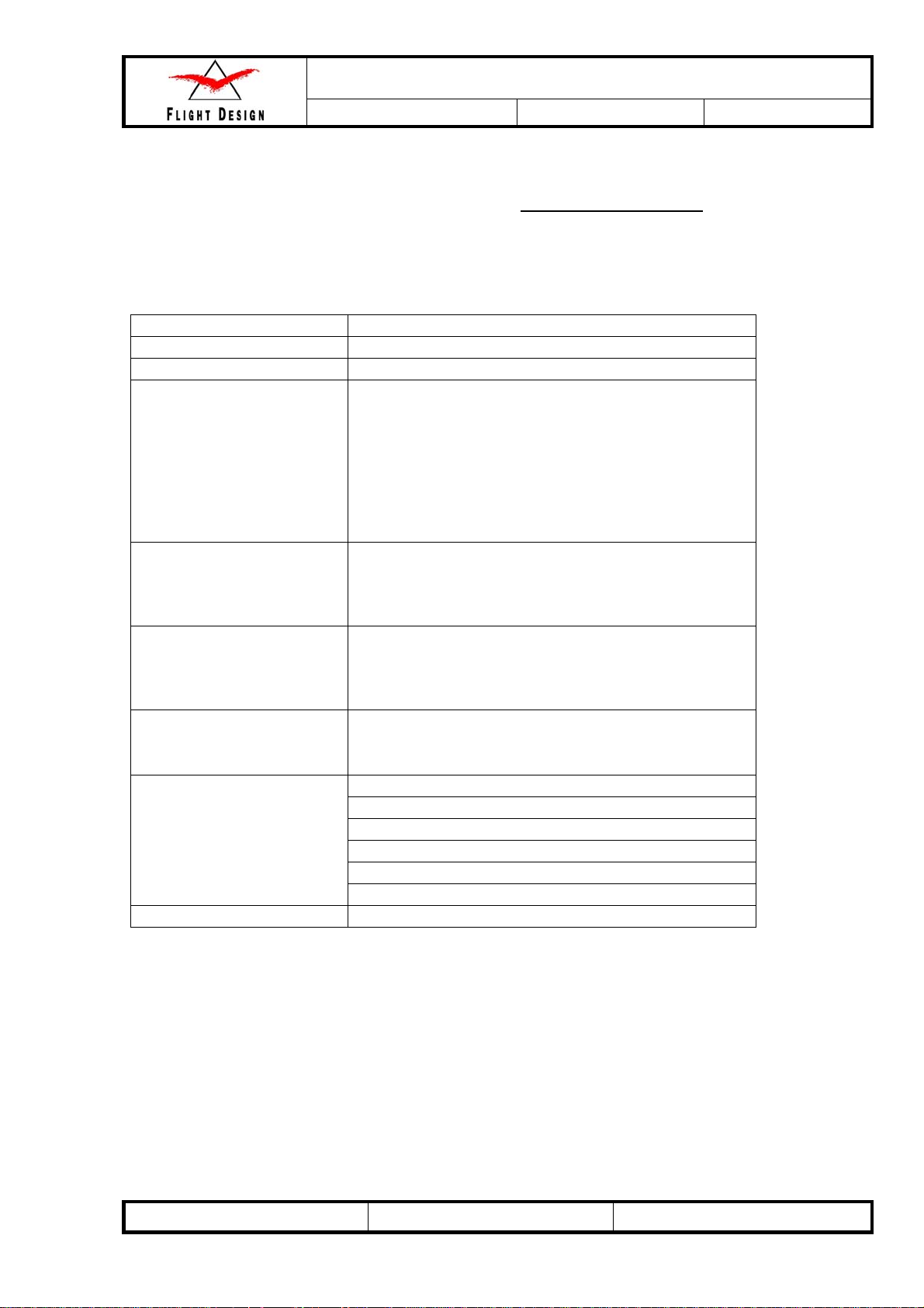
1.8 List of Disposable Replacement Parts
Air filter
Fuel filter
Oil filter
Front & Main wheel
Air filter C2039, Art. C9997770
Fuel Filter 5/16’’, Art C9997813G
Oil filter – according to Rotax maintenance manual
Tyre 4.00-6 BfGoodrich 4PR PowerHoby
Tyre 4-ply 4.00 - 6" /4 PR V-5501 TT (B11)
Tyre 6PR Sava 4.00-6 6PR B11
Tube 3.50-6" not certified
Tube 4.00-6 Pn TR13
Tube Sava, 3.5.00-6 38G11.5, 6 ply
Tundra front wheel
Tundra main wheel
Batteries
Brake Assemblies
Sparkplugs
Tube 4.00-6 Pn TR13
or
Tire 4.00-6 BfGoodrich 4PR PowerHoby
Tyre 4-ply 6,00-6" Air TRAC (420x140)
or
Tyre 4-ply 6,00-6" Air TRAC
Battery Powersafe SBS 8
or
Battery Cyclon
Master brake cylinder, Art C9997205L
O-Ring set for master brake cylinder
Brake pads for magnesium caliper, Art C9997214D
Aeroshell fluid 41 MIL-H-5606 Brake Fluid
Brake disk, Art C9997206M
Caliper, Art C9997205K
Ignition plug - according to Rotax maintenance manual
AF 04800001 Revision No. 3 Date: 14 Sep 2008
Maintenance and Inspection Procedures Manual
Type:
CT
Series:
CTLS
LSA
Page: 1-8
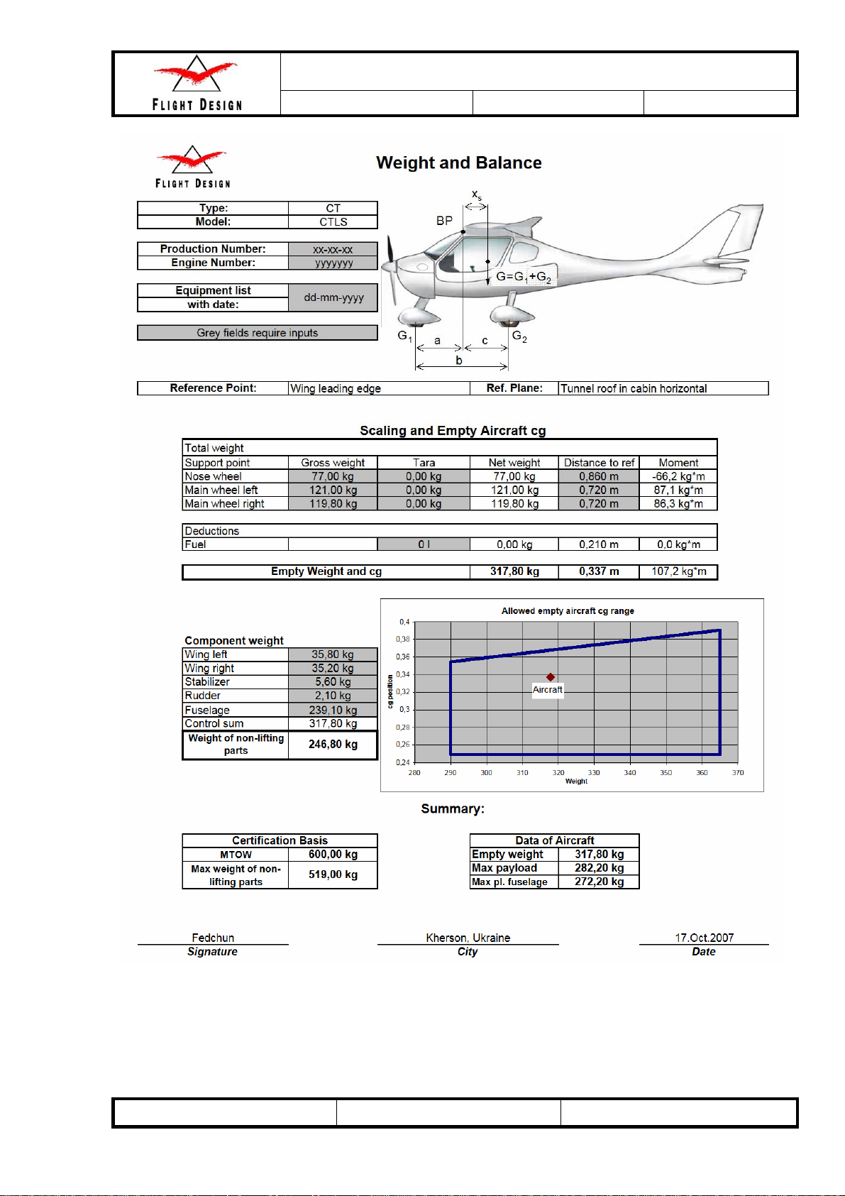
1.9 Weight and Balance Information
Maximum take off weight: 1320 lbs 600 kg
Typical empty weight: 683 lb s 310 kg
Typical useful load 622 lbs 290 kg
Maximum weight per seat: 260 lbs 118kg
Maximum baggage weight per side: 55 lbs 25 kg
Maximum fuel load (34 gal) 205 lbs 93 kg
The acceptable empty center of gravity range is 11.1 to 18.82 inches / 282-478 mm behind the leading
edge of wing.
Weighing:
The airplane is to be put on a level space on three scales or one scale with leveling blocks.
Make certain the plane is leveled using a bubble level put onto the tunnel between the seats.
The location of wheels is marked on the ground by a plumb.
The loaded center of gravity is located behind the leading edge of wing. Spanwise location of the datum is
not important, as the wings are rectangular and un-tapered.
Important:
While determining the loaded center of gravity the aircraft must be leveled.
A Weight and Balance Sheet supplied with each plane. The example of it is shown below.
AF 04800001 Revision No. 3 Date: 14 Sep 2008
Maintenance and Inspection Procedures Manual
Type:
CT
Series:
CTLS
LSA
Page: 1-9
Note: Sample weight and balance sheet only; not valid for the actual aircraft.
AF 04800001 Revision No. 3 Date: 14 Sep 2008

Maintenance and Inspection Procedures Manual
Type:
CT
Series:
CTLS
LSA
Page: 1-10
1.10 Tire Inflation Pressure
Main wheels: 29 PSI / 2 bar
Nose wheel: 29 PSI / 2 bar
1.11 Approved Fluids and Capacities
Quality automotive motor oil as specified by the engine manufacturer has to be used. The engine is not
approved for aircraft motor oil.
Allowed viscosities are listed in Chapter 10 of the Engine Operator’s Manual for all versions of ROTAX
912.
Do not use oil additives.
Oil capacity: 6,4 liq pt – min. 4,2 liq pt 3 l – min. 2 l
Oil consumption: max. 0.13 liq pt/h 0,06 l/h
The fuel valve is purely on / off and has to be in the appropriate maximum position. This engine does not
have a mixture valve or require leaning.
Fuel content: (2 wing fuel tanks for 65 l) 34 U.S. gal 130 l
Maximum fuel available: 33 U.S. gal 124 l
Fuel consumption: max 7 U.S. gal/h 27 l/h
Fuel specification: Premium Automotive Unleaded that conform to ASTM D 4814
Minimum AKI 91 for Rotax 912ULS or AVGAS 100 LL.
Cooling fluid: Cooling fluid in accordance with the Rotax Engine Operation Manual has to be
selected.
Attention: different coolants cannot be mixed! If in doubt, drain the complete
coolant content and replace completely with new coolant of one type.
Warning: Due to its high lead content AVGAS has a detrimental effect on valve seating and causes
greater deposition in the combustion chamber. It should thus only be used if fuel vapor or
octane problems arise or if MOGAS is not available.
Warning: When using AVGAS particular attention must be paid to type of oil used. For details refer
to the valid version of the ROTAX engine manual.
Warning: Engine relevant data given here is not complete. For complete information refer to the
current version of the relevant engine manual from the Rotax company.
Braking fluid: Aeroshell Fluid 41 MIL-H-5606 Brake Fl uid
AF 04800001 Revision No. 3 Date: 14 Sep 2008
Maintenance and Inspection Procedures Manual
Type:
CT
Series:
CTLS
LSA
Page: 1-11
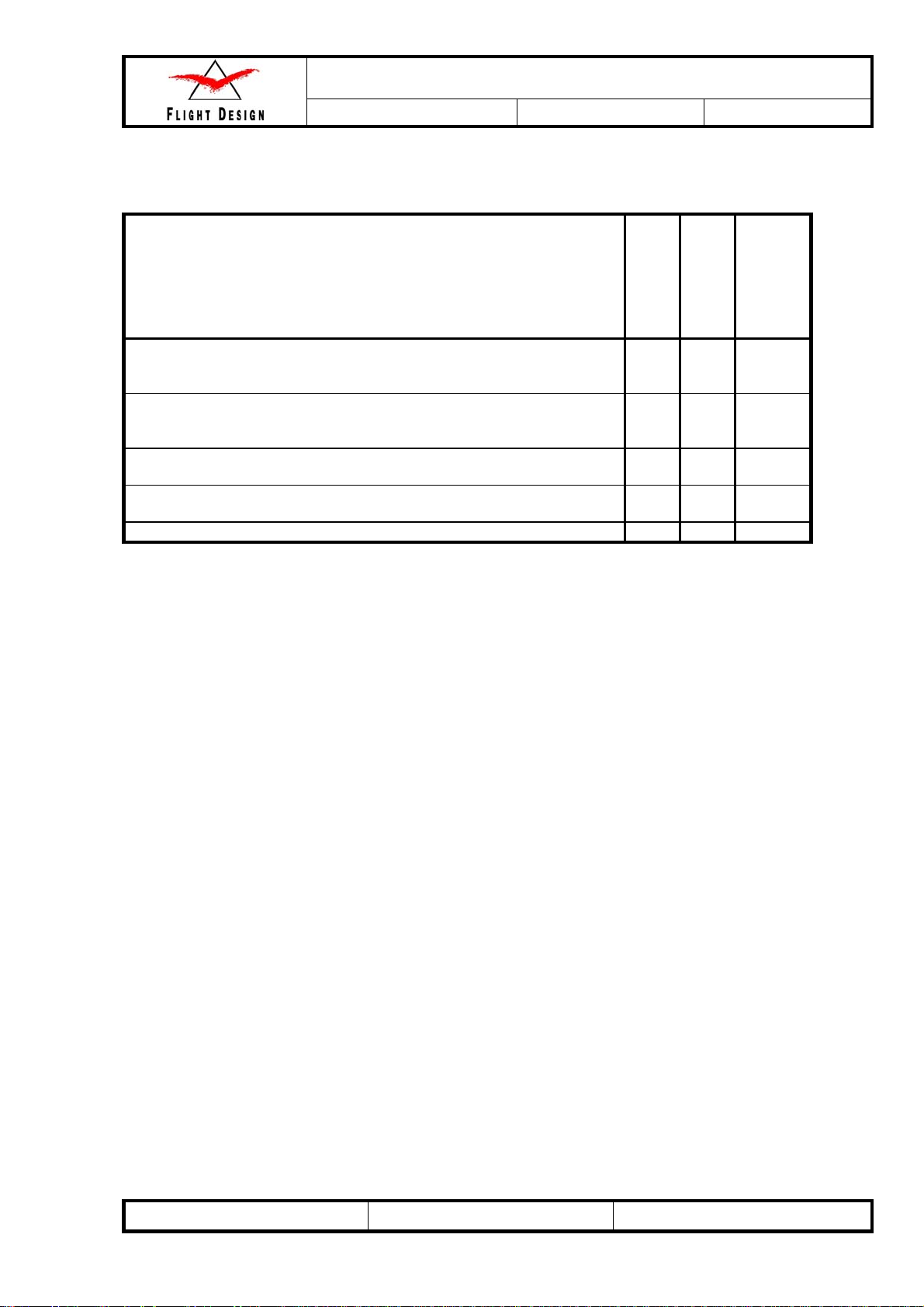
1.12 Recommended Fastener Torque Values and Bolts Installation
ATTENTION!
All bolts has to be mounted up to down, inside to outside or front to aft, unless explicitly stated
otherwise.
Bolt
Nut
Recommended Torques
for class 8.8 (ISO 898)
fasteners
For areas with thick
bonding seams (cotton +
cab-o-sil + resin +
hardener)
Parts of PVC 49 lb-in
Carbon fabric composite
packages assemblies
Plywood bonded into
composite
Glass fiber composite
packages
Metal parts assemblies
(steel, stainless steel,
aluminum alloys)
As long as not stated otherwise within this manual, for bolts using standrad nuts, or botls otherwise
unsecured, Loctite must be applied. Middle strength loctite is to be used when bolts are mounted to
plastic components.
In all cases, used self locking nuts (with plastic locking ring) must be exchanged after new ones at any
time.
Bolt M5 DIN
912-8.8
Bolt M5 DIN
931 -8.8
Bolt M5 DIN
933 – 8.8
Nut M5 DIN
985-8,8
52 lb-in
5.9 N*m
49 lb-in
5.5 N*m
5.5 N*m
49 lb-in
5.5 N*m
40 lb-in
4.5 N*m
49 lb-in
5.5 N*m
53 lb-in
6 N*m
Bolt M6 DIN
912-8.8
Bolt M6 DIN
931 -8.8
Bolt M6 DIN
933 – 8.8
Nut M6 DIN
985-8,8
89 lb-in
10 N*m
80 lb-in
9 N*m
80 lb-in
9 N*m
80 lb-in
9 N*m
71 lb-in
8 N*m
80 lb-in
9 N*m
89 lb-in
10 N*m
Bolt M8 DIN
912-8.8
Bolt M8 DIN
931 -8.8
Bolt M8 DIN
933 – 8.8
Nut M8 DIN
985-8,8
222 lb-in
25 N*m
200 lb-in
22.5 N*m
200 lb-in
22.5 N*m
200 lb-in
22.5 N*m
160 lb-in
18 N*m
200 lb-in
22.5 N*m
222 lb-in
25 N*m
Bolt M5
DIN
7991-8.8
(countersunk)
Nut M5 DIN
985-8,8
52 lb-in
5.9 N*m
40 lb-in
4.5 N*m
49 lb-in
5.5 N*m
49 lb-in
5.5 N*m
31 lb-in
3.5 N*m
49 lb-in
5.5 N*m
53 lb-in
6 N*m
Bolt M6
DIN
7991-8.8
(countersunk)
Nut M6
DIN 985-
8,8
89 lb-in
10 N*m
71 lb-in
8 N*m
80 lb-in
9 N*m
80 lb-in
9 N*m
62 lb-in
7 N*m
80 lb-in
9 N*m
89 lb-in
10 N*m
AF 04800001 Revision No. 3 Date: 14 Sep 2008
Maintenance and Inspection Procedures Manual
Type:
CT
Series:
CTLS
LSA
Page: 1-12
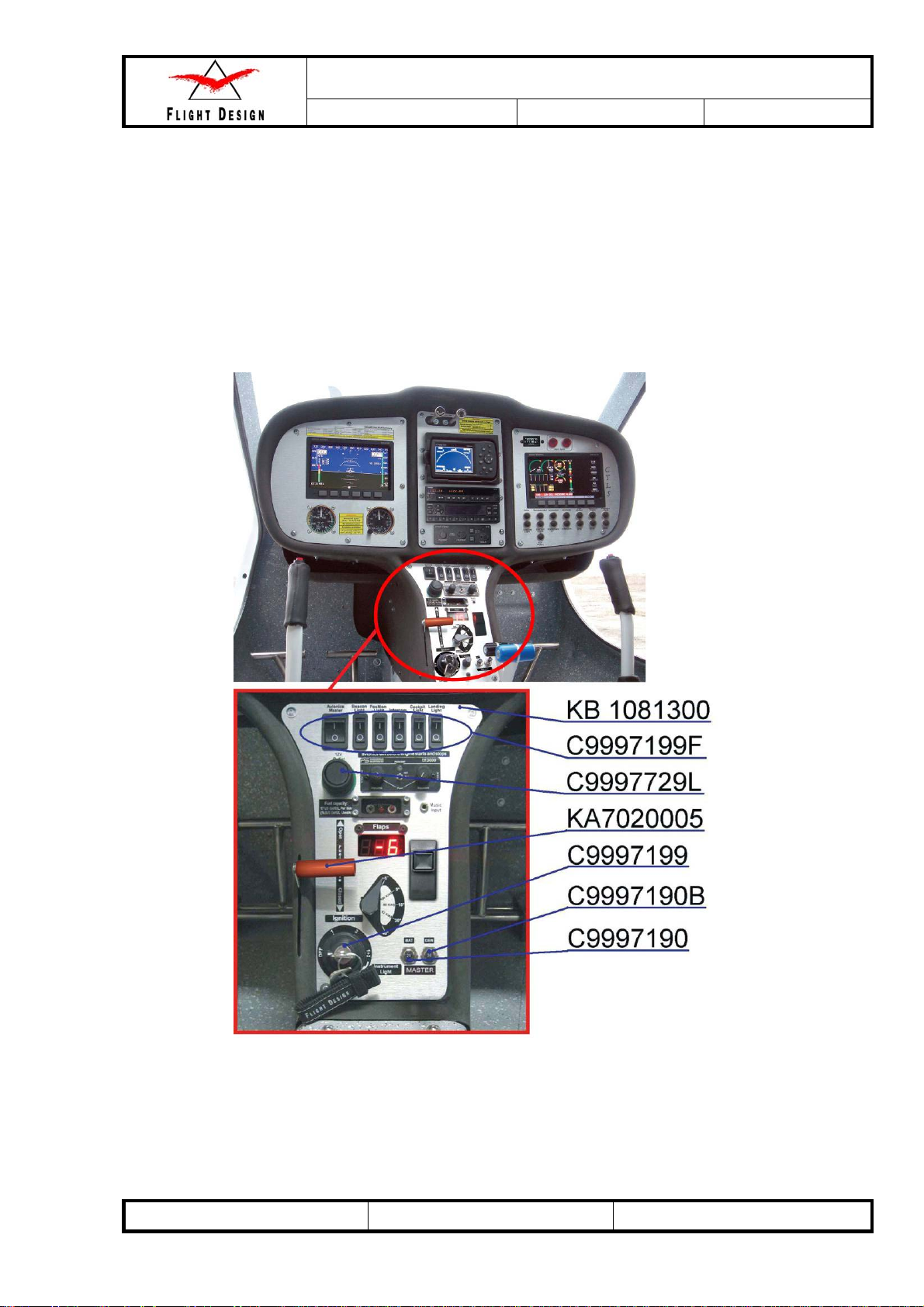
1.13 General Safety Information
ATTENTION!
During all service and repair work beware of activating the Ballistic Parachute system rocket!
While running the engine on the ground, keep away from the propeller.
An accidental engine start is very dangerous! Ensure that the Ignition Switch C9997199 and main
switches [Pushbutton Thermal, 30A C9997190B, Pushbutton Thermal 109S, 25A C9997190 (Fig. 1)] are
turned off!
Fig. 1
AF 04800001 Revision No. 3 Date: 14 Sep 2008
Maintenance and Inspection Procedures Manual
Type:
CT
Series:
CTLS
LSA
Page: 1-13
1.14 Instructions for Reporting Possible Safety of Flight Concerns
Found During Inspection / Maintenance
To report possible safety of flight concerns forward to airworthiness@flightdesignusa.com information
as follows:
Owner (or contact person)
Inspector
Aircraft Make/Model and S/N
Engine Make/Model and S/N
Date of inspection
TT Airframe
TT Engine
Description of the un-airworthy items found
or by writing:
Flight Design USA
Woodstock Airport
91 Route 169,
P.O. Box 325,
South Woodstock, CT. 06267
USA
e-mail: flightdesignusa@rcn.com
www.flightdesignusa.com
using Service Difficulty Report Form
Preferably send an appropriate check list to the same address.
(Appendix III).
AF 04800001 Revision No. 3 Date: 14 Sep 2008
Maintenance and Inspection Procedures Manual
Type:
CT
Series:
CTLS
LSA
Page: 2-1
2 Minimum Levels of Certification:
2.1 General
For each task listed in the maintenance manual, a minimum level of certification is specified. For
example: Owner/Pilot, RLSA-M and A&P.
Where a minimum level of certification is specified, the implication is that an individual who holds a Light
Sport Repairman certificate with a maintenance rating (listed here as a RLSA-M) may perform any task
with the minimum level of competency listed as “Owner/Pilot”, and an A&P may perform any task where
the minimum level of competency is listed as Owner/Pilot, or RLSA-M.
Minimum levels of certification do not preclude the need for additional or task specific training. As a
general rule, additional or task specific training is required for heavy maintenance tasks and is required
on a case by case basis for line maintenance tasks. The requirement for additional or task specific
training will be listed where applicable throughout the manual.
Note: Some tasks may require additional or task specific training for an RLSA-M but not for the holder of
an A&P certificate.
2.2 Levels of certification
Levels of certification used in this manual are:
Owner/Pilot: The owner of an aircraft who holds a pilot certificate but who has not receivedany specific
authorized training. Note: FAA regulations authorize SLSA aircraft owners who hold at
least a sport pilot certificate to perform maintenance as outlined in 14CFRPart43.
RLSA-M: The holder of a LSA Repairman certificate with a maintenance rating. This is generally
considered the minimum level of certification to perform line maintenance of LSA.
A&P: An Airframe and Powerplant mechanic as defined by 14 CFR Part 65 in the U.S. or
equivalent certification in other countries.
For and questions or comments regarding maintenance procedures or minimum levels of certification,
email Flight Design USA at airworthiness@fiightdesignusa.com
.
AF 04800001 Revision No. 3 Date: 14 Sep 2008
Maintenance and Inspection Procedures Manual
Type:
CT
Series:
CTLS
LSA
Page: 2-2
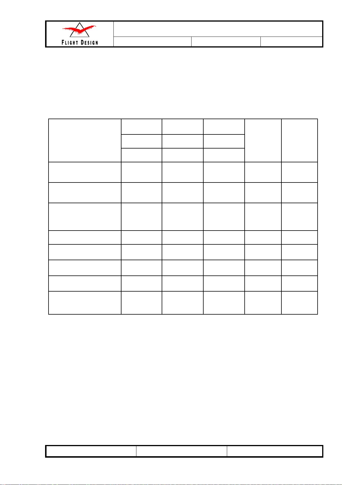
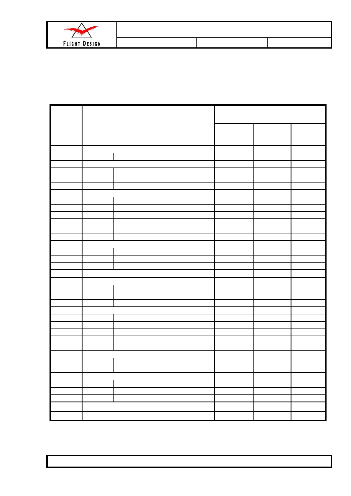
2.3 Required certification level for maintenance procedures
In accordance with applicable standards, the requirements for minimum levels of certification and task
specific training are listed through out this manual. The following table provides an overview on the
allocation of certification levels through out this manual.
Chapter
4 Structures
4.1 Wing
4.1.2 Wing installation and removal
4.2 Nose Landing Gear
4.2.1.4 Nose Landing Gear Inspections
4.2.1.5 Nose Gear Removal
4.2.1.6 Nose Wheel
4.2.2 Main Landing Gear
4.2.2.4 Inspection
4.2.2.5 Main Wheel Fairing Removal
4.2.2.6 Main Wheel Removal
4.2.2.7 Main Strut Fairing Removal
4.2.2.8 Main Gear Struts Removal
4.2.2.9 Wheel Inspection and Maintenance
4.2.3 Brake System
4.2.3.3 Inspection
4.2.3.4 Filling Brake System with Fluid
4.2.3.5 Brake Pads Replacement
4.3 Flight Controls
4.3.1 Aileron
4.3.1.5 Inspection
4.3.1.6 Aileron Installation
4.3.1.7 Aileron Adjustment
4.3.2 Flaps
4.3.2.4 Inspection
4.3.2.5 Flap Installation
4.3.2.6 Flap Adjustment
4.3.3 Rudder
4.3.3.3 Rudder Installation
4.3.3.4 Rudder Deflection Adjustment
4.3.4 Stabilator
4.3.4.4 Stabilator Installation
4.3.4.5 Stabilator Adjustment
4.3.4.6 Balancing of Stabilator Balancer
4.4 Structural Repair
4.5 Painting and Coating
4.3.2.7 Inspection of Flap Controller
Procedure
Microswitches
Minimum Level of Certification
Owner/Pilot RLSA-M
¦
±
±
±
±
±
±
±
±
¦
¦
¦
¦
¦
¦
¦
¦
¦
¦
¦
¦
¦
¦
¦
¦
¦
¦
FD
Training
+
+
+
+
+
+
+
+
+
+
+
AF 04800001 Revision No. 3 Date: 14 Sep 2008
Maintenance and Inspection Procedures Manual
Type:
CT
Series:
CTLS
LSA
Page: 2-3
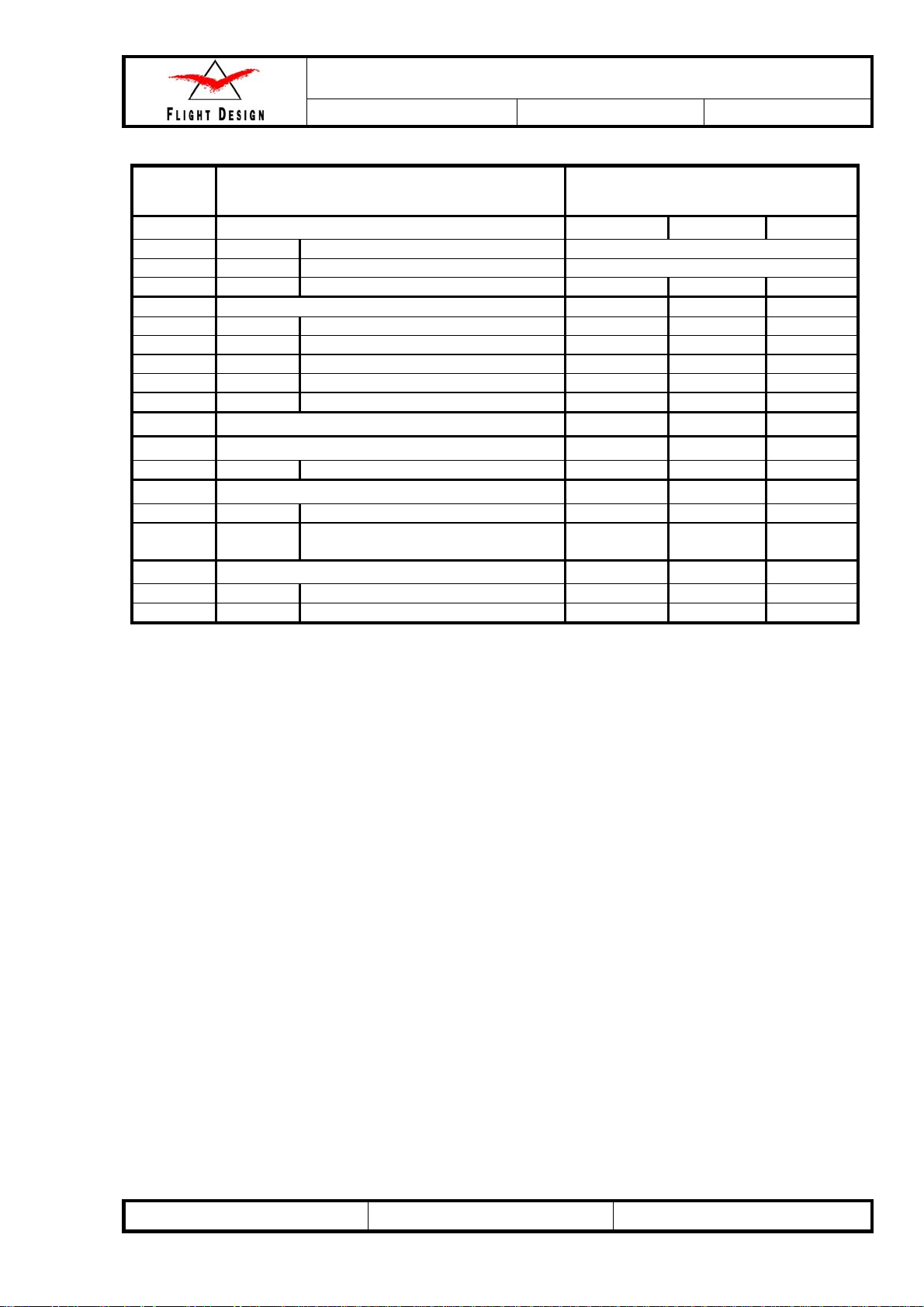
Chapter
5 Engine
5.1 Engine Systems and Accessories case dependent
5.2 Rotax 912 Engine case dependent
5. 3 Carb Heat Control
6 Fuel System
6.4 Fuel System Inspection
6.5 Fuel Flow Check
6.6 Intake Filter Inspection
6.7 Fuel Filter Inspection
6.8 Gascolator Inspection
7 Propeller
8 Utility Systems
8.3 Inspection of Cabin Heat System
9 Instruments and Avionics
9.3 Instrument maintenance
10 Electrical System
10.3.1 Inspection
10.4 Battery Replacement
Where listed, “FD Training” indicates the requirement for Flight Design task specific training. Flight Design
task specific training may consist of one, or a combination of the following:
1. An approved Flight Design maintenance training course,
2. Individual training provided by a Flight Design representative
3. Training via multi-media or electronic means.
Note: For certificated persons such as an A&P, RLSA-M or persons working under the auspices of a
Repair Station, prior experience will be considered when determining the training required.
Important: Participation in training described in this manual shall not be construed as an implicit
authorization by Flight Design to perform inspections or repairs beyond the limitations set forth in the
applicable regulations of the governing aviation authority.
9.4 Inspection of Pitot and Static
Procedure Minimum Level of Certification
¦
¦
¦
¦
¦
¦
¦
System
±
±
±
±
±
+
AF 04800001 Revision No. 3 Date: 14 Sep 2008

Maintenance and Inspection Procedures Manual
Type:
CT
Series:
CTLS
LSA
Page: 3-1
3 Aircraft Inspections
The following pages contain checklists suitable for performing periodic aircraft inspections of the Flight
Design CTLS.
Note: The ROTAX 912 Maintenance Manual contains a periodic maintenance schedule for the 912 ULS
engine.
Engine checks at 100hour according to Rotax maintenance manual are highly recommended to
be conducted on time out of safety reasons.
Condition inspection checklist
Owner’s Name: ________________________________________________
Inspector’s Name: ______________________________________________
Aircraft Make/Model: Flight Design CT / _________________. S/N: __________________.
Engine Make/Model: ____________________________________. S/N: __________________.
Date of Inspection: _____________
TT Airframe: __________________
TT Engine: ___________________
AF 04800001 Revision No. 3 Date: 14 Sep 2008
Maintenance and Inspection Procedures Manual
Type:
CT
Series:
CTLS
LSA
Page: 3-2
3.1 Aircraft Records
CT Inspection and/or Required Maintenance Checklist
100hour
Aircraft logbooks. Determine total times, times since overhaul and
times since last required or recommended maintenance checks and
record on Inspection Coversheet.
Safety Directives (SD’s), Airworthiness Directives (AD’s) and
Service Bulletins. Check SD’s, AD’s, and Service Bulletins which
may need to be complied within the inspection.
Aircraft records. Check for presence and condition of aircraft federal
registration form and airworthiness certificate.
Aircraft Operating Instructions (AOI). Check AOI revision number to
be actual, Equipment List and latest Weight and Balance information.
Annual
of Certification
Minimum Level
RLSA-M
RLSA-M
RLSA-M
RLSA-M
AF 04800001 Revision No. 3 Date: 14 Sep 2008

Maintenance and Inspection Procedures Manual
Type:
CT
Series:
CTLS
LSA
Page: 3-3
3.2 Run-up
Run-up shall be done prior to any inspection.
Run-up shall at least take long enough to bring all temperatures to levels acceptable for takeoff.
Inspection:
CT Inspection and/or Maintenance Checklist
1. 100hour
2. Annual
ELT battery due:
Altimeter / Transponder test due:
Systems Pre-inspection Post-inspection
Starter
Oil pressure psi psi
Brakes
Instruments & avionics
Ignition ground test
(See Chapter 10.3.5 of the Operator’s
Manual for all versions of ROTAX 912)
Oil temperature
°F °F
WARNING: Ensure cylinder heads temperature (CHT) and oil temperature are
within limits.
Cabin heat
Oil pressure psi psi
Idle RPM RPM RPM
WARNING: Allow engine to cool to 300°F (CHT) before shutdown.
All exterior lights are off
Check for fuel odors in cabin
Check for fuel stains on floor
Check fuel valve off function
Notes:
AF 04800001 Revision No. 3 Date: 14 Sep 2008
3.3 Post-Run-up
CT Inspection and/or Required Maintenance Checklist
Maintenance and Inspection Procedures Manual
Type:
CT
Series:
CTLS
LSA
100hour
Page: 3-4
Annual
Minimum Level
of Certification
Engine cowling. Remove engine cowling.
Engine oil. Check the level of oil and follow the Operator’s Manual for
all versions of ROTAX 912.
Exterior lights. Check operation of landing lights (if applicable),
position lights, and strobe lights.
Interior lights. Check operation of interior lights (if applicable).
Flight controls. Check for smooth operation of all flight controls with
flaps in retracted and extended positions. Leave flaps in the full up
position when checks are completed.
Door apertures protection. Check protection for wearing and flanges
for cracks.
Rudder neutral position system. Check operation.
Environmental Control System (ECS). Check operation of the door
window vents.
Trim tab. Check trim tab position and indicator reading.
Brake System. Check wheel chocks and disks for wearing. Check the
level of fluid in the hydraulic system. Inspect the protection PVC hoses
in the places where brake lines go through the fuselage skin
(see p. 4-32 - Chapter 4.2.3.5.2).
Battery. Fully charge and clean up the battery surface and cables.
Check the battery for reliable contact with the cables.
Fairings, access panels, seats, carpets, covers, and spinner.
Remove for inspection to ensure access. Check for missing or
unscrewed bolts and nuts.
RLSA-M
RLSA-M
RLSA-M
RLSA-M
RLSA-M
Owner/Pilot
RLSA-M
Owner/Pilot
RLSA-M
Owner/Pilot
Owner/Pilot
RLSA-M
AF 04800001 Revision No. 3 Date: 14 Sep 2008

Maintenance and Inspection Procedures Manual
Type:
CT
Series:
CTLS
3.4 Propulsion System
CT Inspection and/or Required Maintenance Checklist
Cleaning. Clean the engine as required in the Maintenance Manual
for ROTAX Engine Type 912 Series.
Engine. Inspect all systems as required in the Maintenance Manual
for ROTAX Engine Type 912 Series.
Induction system. Check connection of manifolds between Air filter
box and carburetors. Check the carburetor heater choke in the Air
filter box for operating. Check for fuel leakage nearby carburetors.
Induction air filter. Inspect for cleanliness and condition of sealing
surfaces. Replace filter, if damaged.
Cabin Heater. Check clamps and heater attachments. Check the
manifold for holes and attachments.
LSA
100 hour
*
*
Page: 3-5
Annual
Owner/Pilot
Owner/Pilot
Owner/Pilot
Owner/Pilot
RLSA-M
of Certification
Minimum Level
Exhaust system. Inspect entire system for cracks, and security.
Fuel sight gages. Inspect for security and presence of fuel
leakage. Check operation of throttle and choke controls. Ensure
levers hit stops before cables reach end of travel.
Fuel manifold valve and distribution lines. Inspect for evidence
of fuel leakage. Inspect distribution lines for cracks, and signs of
leakage.
Gascolator. Open gascolator, remove filterand check for
cleanliness. Clean filter and re-install.
Fuel lines. Inspect all flexible fuel hoses for routing, chafing,
security, and signs of leakage.
Fire Protection Hoses. Icheck for condition and integrity on all fuel
and oil lines inside the engine compartment.
Fuel Flow Rate. Check fuel flow rate to be correct every 100 hrs.
Compare value with previous value. In case of significant variations
or too little flow refer to the relevant section of the Maintenance
Manual.
Spinner. Inspect for cracks, security to propeller. Clean inside of
spinner.
Propeller hub. Inspect for cracks, corrosion. Re-torque all
mounting nuts, if loss of torque is suspected on any nut.
Propeller blades. Inspect for play, dents, nicks, cracks, corrosion,
pitting, and leading edge erosion.
Engine cowlings. Inspect for cracks, chafing, heat damage, and
delamination, evidence of exhaust leakage, condition of fastening
system, and condition of paint.
Landing and taxi lights. Inspect for cracks, security of mounting,
and cleanliness and condition of lens cover. Operate landing lights
in a dark area and ensure that lights are properly aimed. If lights are
not properly aimed, adjust as required.
Firewall. Inspect for cracks, buckling, and other signs of damage.
Inspect all items attached to firewall for security.
* - Engine checks at 100hour according to Rotax maintenance manual are highly recommended to be
conducted on time out of safety reasons.
RLSA-M
RLSA-M
Owner/Pilot
Owner/Pilot
RLSA-M
RLSA-M
RLSA-M
Owner/Pilot
RLSA-M
Owner/Pilot
Owner/Pilot
Owner/Pilot
Owner/Pilot
AF 04800001 Revision No. 3 Date: 14 Sep 2008
 Loading...