

Flight Deck SC-6502, SC-M500, SC-6501, flightdeck sc6501, flightdeck sc6502 Service Instructions Manual
...
SI-7AP1E
SERVICE INSTRUCTIONS
Cycle Computer
SC-6502 / SC-6501/ SC-M500
t
Be careful not to pay excessive
attention to the computer data while
riding, otherwise you might have an
accident.
NOTE;
* The all clear (AC) button is used to clear the main unit memory.
* Never disassemble the main unit, as it cannot be reassembled.
* The main unit is fully waterproofed to withstand wet weather
conditions; however, do not deliberately place it into water.
* Avoid leaving the main unit exposed to extremely hot weather
conditions.
* Handle the main unit carefully, and avoid subjecting it to any shocks.
* Do not use thinner or other solvents to clean parts such as the main
unit and sensor, as they may dissolve the part casings.
* To clean these parts, wipe them with a cloth soaked in a weak mixture
of neutral detergent and water.
* If using the SM-6501/M/MD together with an LED lamp from another
manufacturer, the speed measurement function may not work correctly.
If using an LED lamp from another manufacturer, it is recommended
that you use the SM-6500-RS.
Specifications
Meter
Bracket/Sensor unit
SC-6501 / SC-M500SC-6502
SM-6501 SM-6501-MD
STI lever
ST-7700- C
ST-6510
ST-5500-CA
ST-4400
ST-3300/3303
SM-SC70
ST-7800
ST-M510
SL-M510
SM-6501-M
ST-M952 SL-M952
ST-M750 SL-M750
ST-M570 SL-M570
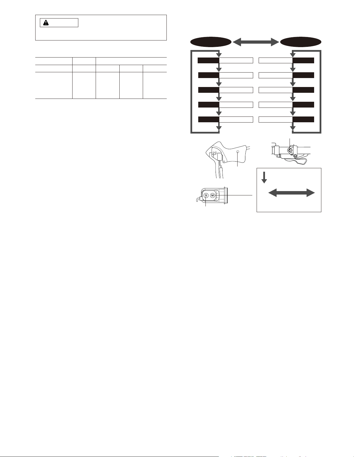
1. Display Modes
“Current speed” and “Gear indicator (bar)” are always displayed
mode 1 mode 2
TIM Trip time
DST Trip distance
ODO ODO meter
STW Stop watch
CLK Clock rpmCadence
VEL
Main display cadence
MAX
Maximum speed
AVEAverage speed
CNTLap counter
Press mode button
once
Press mode button continuously
for 2 seconds or more
Mode Button
SM-6501-MD
WARNING
Mode Button
SM-SC70
SM-6501
SM-6501-M
ST/SP button
Mode button
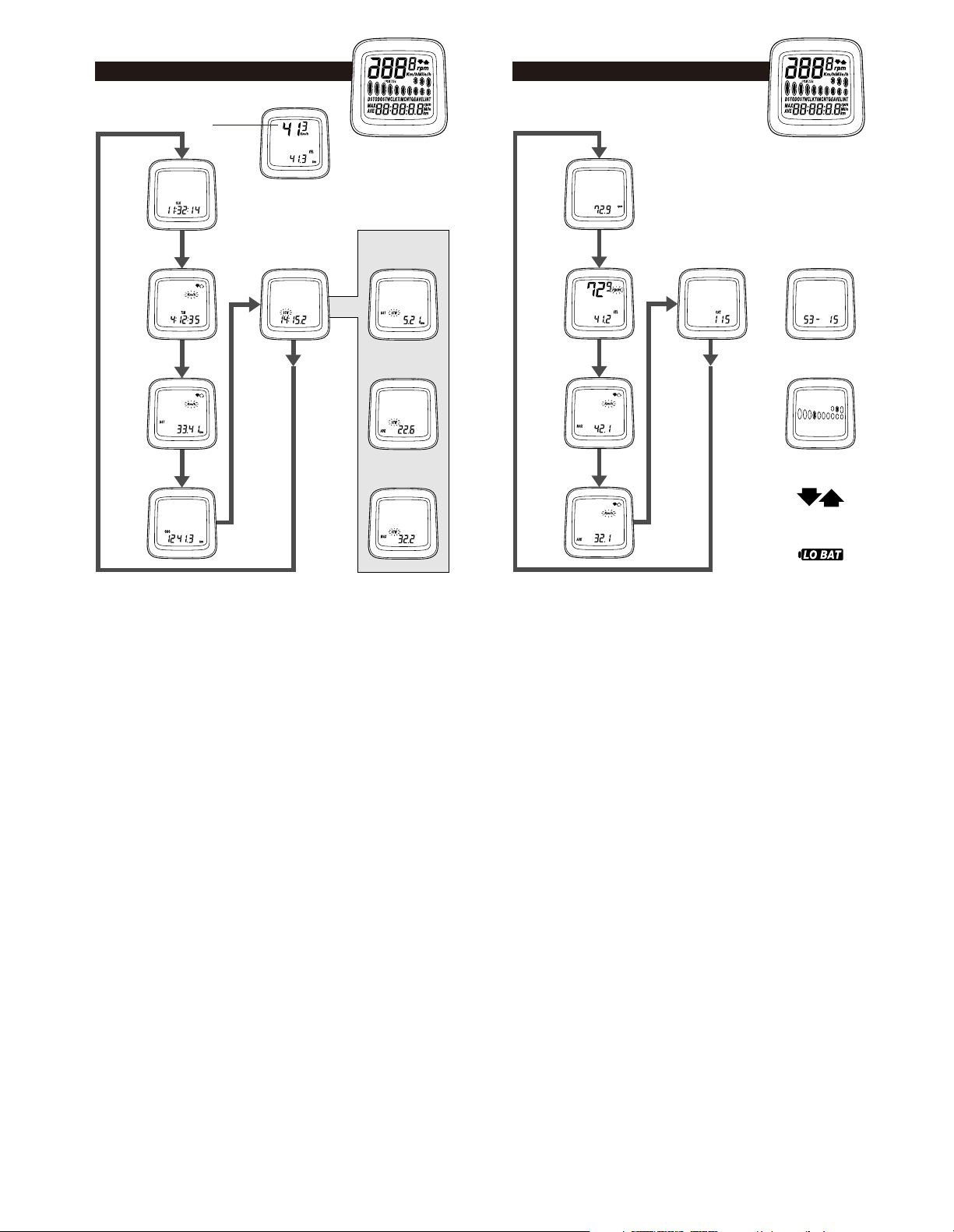
2. Display Contents
mode 1 mode 2
Current
speed
(VEL)
Clock
(CLK)
Trip time
(TIM)
Trip distance
(DST)
ODO meter
(ODO)
Stop watch–
trip distance
(DST STW)
Stop watch–
average speed
(AVE STW)
Stop watch–
maximum speed
(MAX STW)
Stop watch
Cadence
(rpm)
Main display
cadence
Maximum
speed
Average
speed
No. of gear teeth
(digital)
Gear indicator
(bar)
Pace Arrow
Low battery display
Lap counter
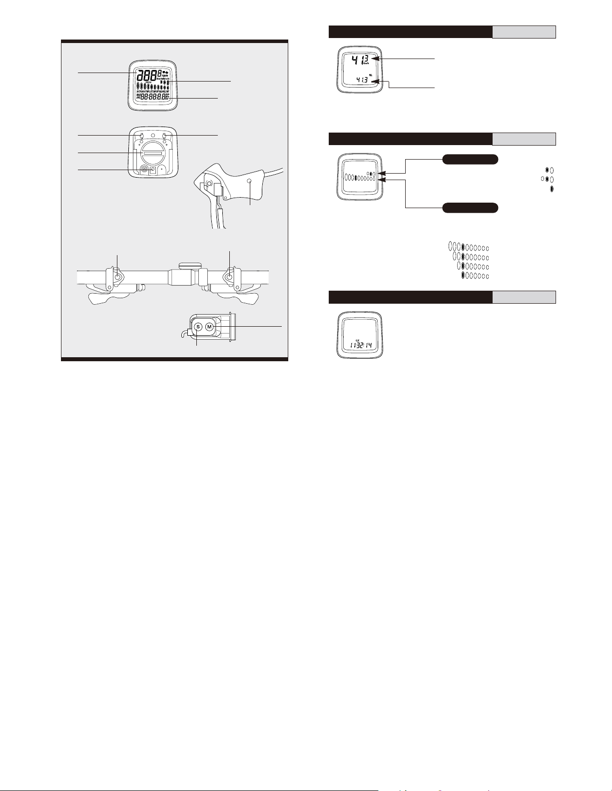
(1)
Current speed (VEL
)
km/h, mph
When main
display cadence
appears on top
Current speed
will appear in
the sub - display
0.0 (2.0) - 130.0km/h
0.0 (1.2) - 80.0mph (Range)
The current speed will appear at
the top of the main display.
(2)
Gear indicator (bar
)
Front display
Rear display
For double : Low position
•••••
For triple : Middle position
••••
For single :
••••••••••••••••••••
Displays;
Top for smallest sprocket
Low for largest sprocket
(3)
Time display (CLK
)
24-hours clock
Gear indicator bar will not appear
if the sensor wire is not connected
or it has been turned off.
Clock will appear when changing
mode 2 to mode 1 and during
power saver function.
7th sprocket for 10-sprocket set ••••••••
7th sprocket for 9-sprocket set •••••••••
7th sprocket for 8-sprocket set •••••••••
7th sprocket for 7-sprocket set •••••••••
3.
Name and function of each part
Front
Rear
STI Brake Bracket
<
ST-7800, ST-7700-C, ST- 6510,
ST-5500-CA, ST-4400, ST- 3300/ 3303
>
<
ST-M510, SL- M510
>
ST/SP button
Mode button
Main Display
1. Current speed
(VEL)
8. Cadence
Sub Display
3-7, 9 -10
2. Gear indicator
(bar)
Switch B
AC All clear
Switch
Battery cap
Switch A
R.H. side lever :
Mode button
L.H. side lever :
ST/SP button
<
ST-M952, ST-M750, ST-M570,
SL-M952, SL-M750, SL-M570
>
ST/SP button
Mode button
 Loading...