

Flightcom 403mc Installation & Operation Manual
Model 403mc Voice Activated INTERCOM
INSTALLATION/OPERATION MANUAL
PLEASE READ THIS MANUAL THOROUGHLY
BEFORE USING THE INTERCOM
and consult with your A & P Mechanic or Certified
Repair Station prior to installation.
SYSTEM OVERVIEW
The Flightcom Model 403mc intercom is a monaural unit compatible with most
aviation headsets. Installation of up to four stations is possible using optional
jacks. The unit provides two station radio transmit capability.
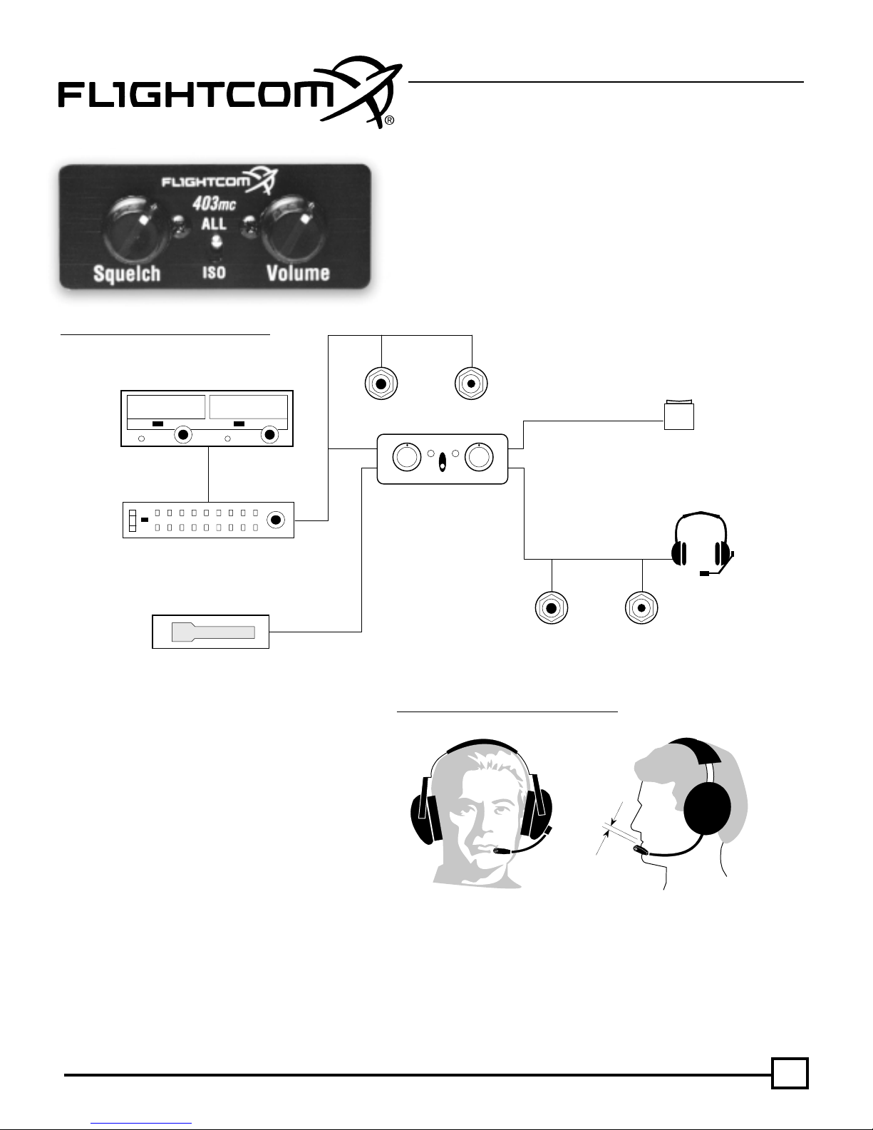
Fig. 1 Typical Connection Configuration
Aircraft Radio
Optional Audio Panel
MUSIC
Optional
OPERATING PROCEDURES
Standby Jacks
ALL
Squelch
Front Panel
Fig. 2 Correct Placement of Boom and Mi
Volume
ISO
HEADSET JACKS
for 2-4 Places
Headphone
Jack
Microphone
c
PTT Switches for
1-2 places
Optional
Jack
Plug headsets into the proper intercom jacks. When using
stereo headsets, put the stereo/mono switch in the mono
mode. Turn on the aircraft master switch and avionics master ,
if so equipped.
Initially set the intercom volume control to the 11 o’clock
position and the squelch control to the 3 o’clock position. Turn
up each headset volume all the way and position your boom
mic 1/8" from your lips and at the corner of your mouth for
best results. Noise canceling mics will not operate correctly if
they are more than 1/8" from your mouth. While speaking
loudly, adjust the intercom volume control to a comfortable
ZERO to 1/8"
from mouth
listening level.
Squelch Control: The squelch control should be set as f ar clockwise as possible while still blocking the background noise . When adjusting
the squelch, be sure no one is talking. Re-adjust this setting in flight to compensate for different noise levels.
Note: If the squelch is set too high (counter-clockwise) your voice will be cut out unless you talk very loudly. If the squelch is set too low
(clockwise) the background noise will be heard occasionally.
1
RADIO USE
Normal radio use is unaffected by proper installation of the intercom, and passengers will now be able to hear each other, the aircraft radio,
and sidetone, (if radio generated). To transmit on the radio, push the yok e PTT s witch associated with your headset, (pilot or copilot). There is
no need for the passengers to stop talking while the pilot is transmitting. Only the person whose push-to-talk s witch is depressed will be heard
over the radio . An instructor can talk to a student pilot o ver the intercom, while the student is transmitting o ver the radio w ithout the instructor’s
voice also being broadcast. Music will nev er be transmitted. If your push-to-talk s witch fails, y ou can use an existing handheld mic to talk on the
radio while listening over the intercom.
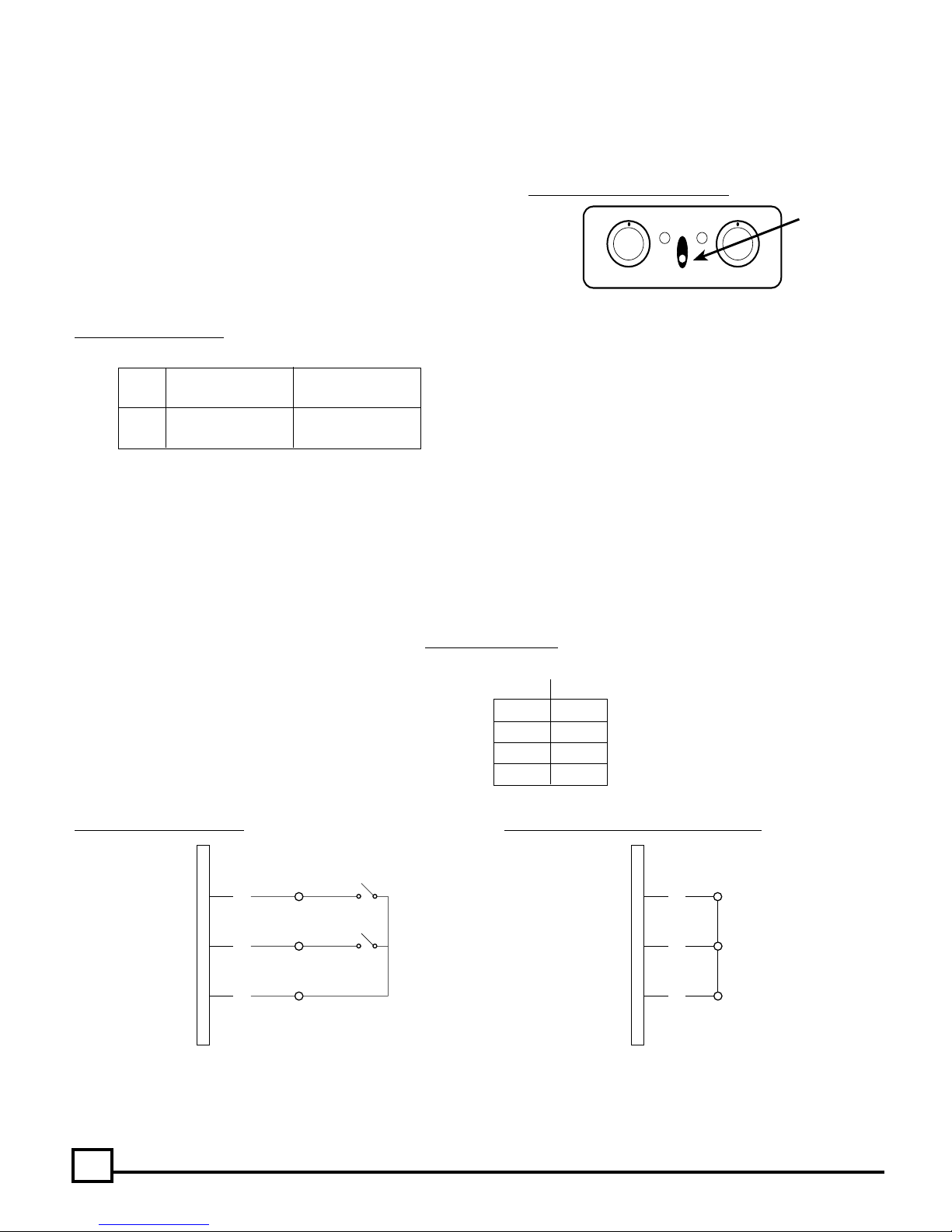
Pilot Isolate Switch: For normal intercom and transmit operations place the
PILOT ISOLATE switch in the ALL position. Selecting the ISO setting will
isolate the pilot from the intercom conversation (and music) and connect the
pilot directly to the aircraft radio. Placing the PILOT ISOLATE switch in the
ISOLATE position will prevent the passengers from hearing the aircraft radio
receptions as well as the pilot’s transmissions to ATC. Passengers can con-
tinue to use the intercom, including a music source.
Fig. 4 Pilot Isolate Switch
Pilot Hears: All Others Hear:
ALL Intercom Intercom
Radio, Music Radio, Music
ISO Radio Only No pilot, but
Intercom, Music
Intercom Failsafe Feature: The integr al f ailsaf e relays in the intercom will connect the pilot’s headset directly to the aircraft radio in the ev ent
of a power supply interruption to the intercom.
Music Muting: When music or other input is being pla yed via the auxiliary input, an instant muting feature will pre vent interf erence with critical
voice communications.
Note:
This feature must be wired into the wiring harness when the intercom is installed into the aircraft. (See Figure 12 CONNECTION
(See Figure 6a below)
SCHEMATIC). (Connect pin #24 on the DB25 connector to pin #25 to permanently install this feature. A switch installed between these pins
would give the option of using or not using this muting feature.) (See Figure 6a below)
Fig. 3 Pilot Isolate Switch Location
ALL
Squelch Volume
Intercom Front Panel
ISO
Pilot Isolate
Toggle Switch
Intercom Muting: This instant muting feature will allow
the incoming radio communications to have priority over
the intercom feature and will mute the intercom audio.
Note:
This feature must be wired into the wiring harness
when the intercom is installed into the aircraft. (See Figure
12 CONNECTION SCHEMATIC) Connect pin #23 on the
DB25 connector to pin #25 to permanently install this feature. A switch installed between these pins would give the
option of using or not using this muting feature.
Fig. 5 Intercom Muting
Pin 25 (common) connected to: (indicated with “x”)
Pin 23 Pin 24
No Muting
x Radio Mutes Intercom only
x Radio Mutes Music Only
x x Radio Mutes Intercom Audio and Music
(CONNECTOR PRE-WIRED FOR COMPLETE RADIO PRIORITY)
Fig. 6a Selectable Auto Mute Fig. 6b Factory Shipped Muting Configuration
DISABLE
DB25
CONNECTOR
23
24
25
ENABLE
DISABLE
ENABLE
INTERCOM MUTE
MUSIC MUTE
DB25
CONNECTOR
23
24
25
Complete Radio Priority: Connecting pins #23, #24 and #25 on the DB25 connector will give the radio complete priority and the radio will
override all other audio in the model 403mc. Note:
radio priority. (See Figure 6b)
2
The DB25 connector shipped with the model 403mc intercom is pre-wired for complete
INTERCOM INSTALLATION
For In-panel or Under-panel Mount: The intercom bo x measures 2.375"W x 1"H x 2.625"D. Depending on the type of housing used on your
selected DB25 connector, allo w at least an additional 3/4" in depth for mounting. If you’re using the Flightcom supplied DB25 connector, allo w
an additional 2" in depth. The intercom can be placed either vertically or horizontally in the instrument panel, under the panel, or in any other
suitable location in the aircraft.
For In-panel Mounting: Leave the two potentiometer nuts in place on the intercom. Mark the panel by placing the front panel plate in the
location of your choice, either vertically or horizontally, and trace the hole location for drilling.
For panels less than .1" thick (Drill Template #1 — See figure 10) use a 9/32" drill for the controls. For panels between .1" and .2" thick (Drill
Template #2 — See figure 10) use a 1/2" drill or punch so the nuts can be cleared.
Insert the intercom through the panel and the faceplate of your choice and install the two 4-40 x 1/2" mounting screws. DO NOT USE ANY
REPLACEMENT SCREWS LONGER THAN 1/2 INCH! Install knobs so that the mark points to the 7 o’clock position when fully counter-cloc kwise .
Fig. 7 Control Panel Installation
Note:
Use the two flathead screws when mounting the
horizontal faceplate. Use the two panhead screws when
AIRCRAFT PANEL
DO NOT
Remove
These Nuts
INTERCOM
Knob
4-40 Screws(2)
Knob
INTERCOM
FRONT PANEL
mounting the vertical faceplate.
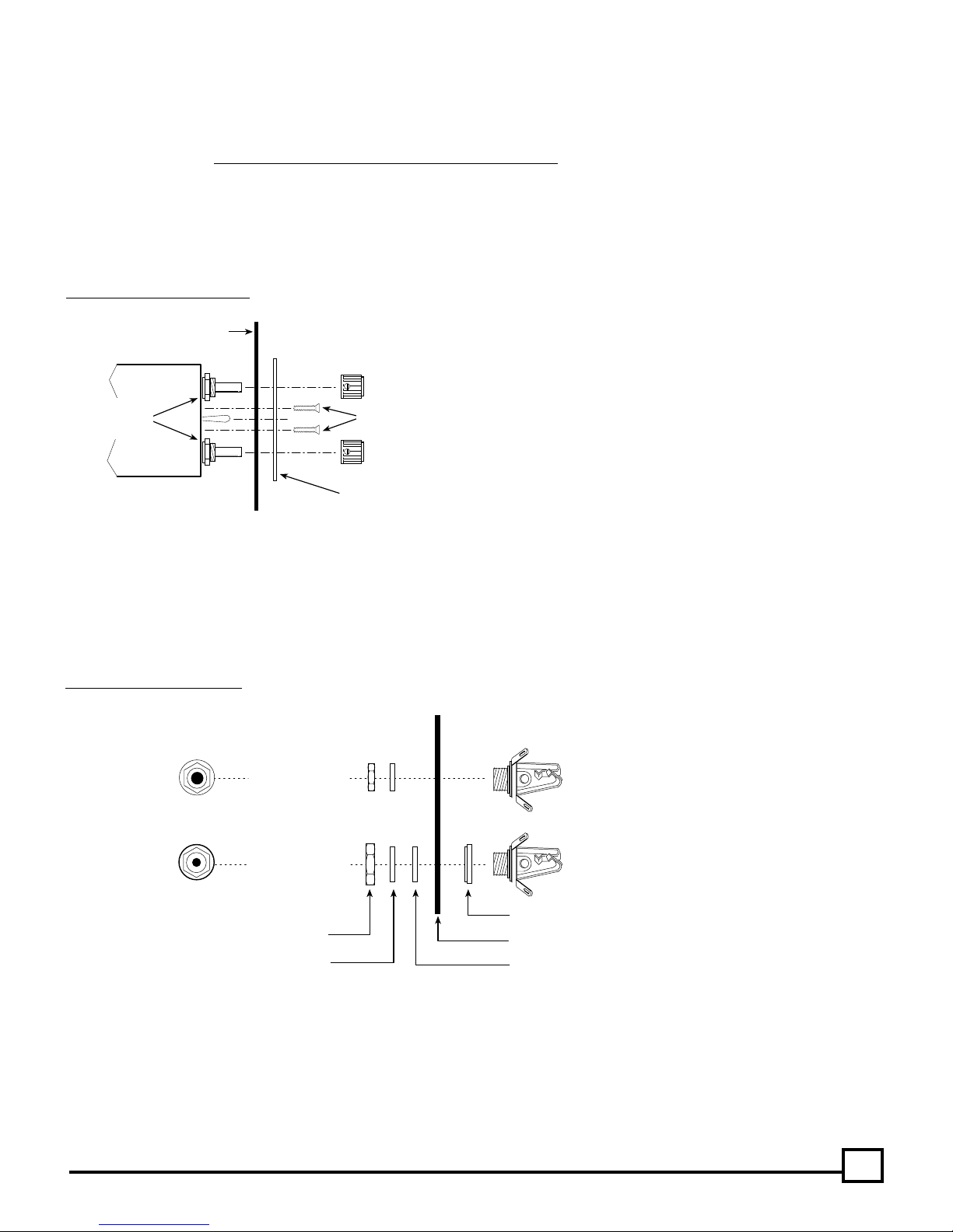
Headphone and Microphone Jacks: Choose a location f or each pair of jacks (one microphone, one headphone) f or each station, up to a total
of 4 stations. Carefully mark each location. Drill a 3/8" hole for each headphone jack and a 1/2" hole for each microphone jack/shoulder
washer. Connect the jacks with the proper wire and according to the wiring diagram on page 7.
The intercom microphone jacks must be insulated from the airframe, but the headphone jacks may either be grounded to the airframe or
insulated with a separate ground wire running back to the intercom.
Note: Do not use the same ground wire for the headphone and microphone jac ks.
Fig. 8 Jack Mounting Diagram
TOP VIEW
SIDE VIEW
Drill 3/8" Hole
Drill 1/2" Hole
HEX NUTS
WASHERS
(Headphone and microphone jack info continued next page.)
Headphone Jack (Large ID)
Mic Jack (Small ID)
SHOULDER WASHER (Mic Jack Only)
AIRCRAFT PANEL
INSULATING FLAT WASHER
3
 Loading...