

Flightcom 403, 403d Installation & Operation Manual
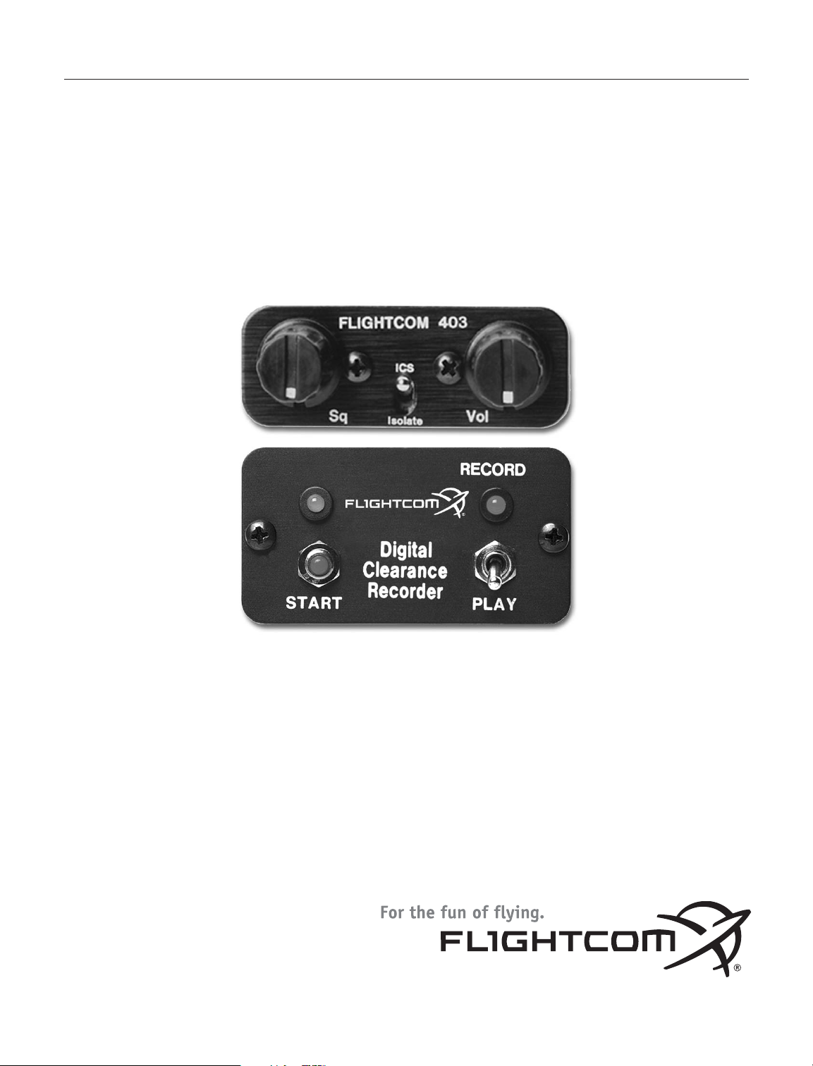
MODEL 403 Panel-Mount Intercom
MODEL 403d Panel-Mount Intercom
with Digital Clearance Recorder (DCR
™
)
INSTALLATION/OPERATION MANUAL
CONGRATULATIONS! You have just purchased the best value in “STATE OF THE ART” cockpit communication.
This unit is equipped with many new convenient features that will add to your flying enjoyment.
PLEASE READ THIS MANUAL BEFORE USING THE INTERCOM AND CONSULT WITH YOUR
A & P MECHANIC OR REPAIR STATION PRIOR TO INSTALLATION.
Flightcom Intercom Models 403 and 403d are full dual-channel stereo capable units also compatible with
monaural headsets. Installation of up to six places is possible with the jacks included with both models. Three
of these six places have transmit capability over aircraft radios. Model 403d also includes the Digital Clearance
Recorder (DCR™), which enables instant recall of voice information.
SYSTEM OVERVIEW
SPECIFICATIONS
Size: 5”L x 2.4”W x 1.2”H
Weight: 5.0/5.6 oz.
Output: 375 milliwatts into each channel of up to six 150 Ohm headsets. Sound level remains constant
regardless of the number or the type of headsets connected. Power Requirements: 0.16 amps, 12-28 VDC
Warranty: two year parts and labor
PARTS LIST
403 or 403d intercom, labeled
Accessory Package:
1 25-pin D-sub connector (male)
1 25-pin D-sub connector housing
1 Large control panel
1 Small control panel
2 Knobs
6 Stereo/mono switches with
mounting nuts and washers
2 4-40 mounting screws
6 Stereo/mono control panels
4 6-32 screws
1 Allen wrench
Manual
Warranty Card
Model 403d also contains:
1 Wiring harness for DCR, with button, switch, and LED
1 DCR control panel
2 LED holders
2 Sheet metal mounting screws
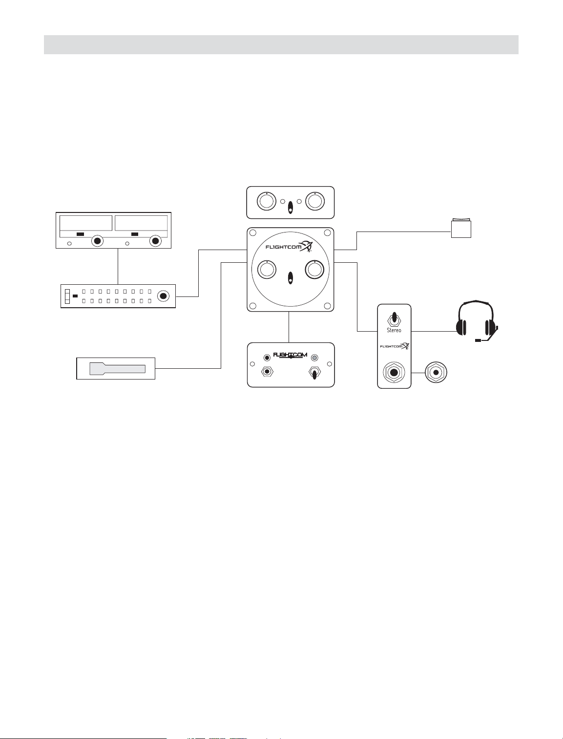
Figure 1 - Model 403/403d Typical Connection Configuration
ICS
Isolate
FLIGHTCOM 403
Sq Vol
STEREO
Optional
DCR Control Panel
Optional
PTT Switches for 1-3 places
FLIGHTCOM 403
HEADSET JACKS
for 2-6 Places
Optional
Stereo or
Mono
ICS
Squelch Volume
Isolate
403
INTERCOM
Optional
SMALL Panel
Headphone
Mono
Stereo/Mono
Switch Panels (2-6)
Microphone
Jack
Aircraft Radio
Audio Panel
Optional
PLAY
RECORD
START
Digital
Clearance
Recorder
®
Figure 1 - Model 403/403d Typical Connection Configuration
Jack package:
6 Headphone jacks
6 Microphone jacks
12 Metal nuts
12 Metal washers
6 Black fiber shoulder washers
6 White nylon or fiber washers
SET-UP and INSTALLATION
Mounting the Intercom to the Aircraft
The 403 and 403d intercoms can be mounted to the aircraft in either of the following ways:
• Standard 21/4inch Instrument Hole Mounting
• Through-panel or Under-panel Mounting
Standard 2
1
/4inch Instrument Hole Mounting
To mount the intercom with standard 21/4inch hole mount:
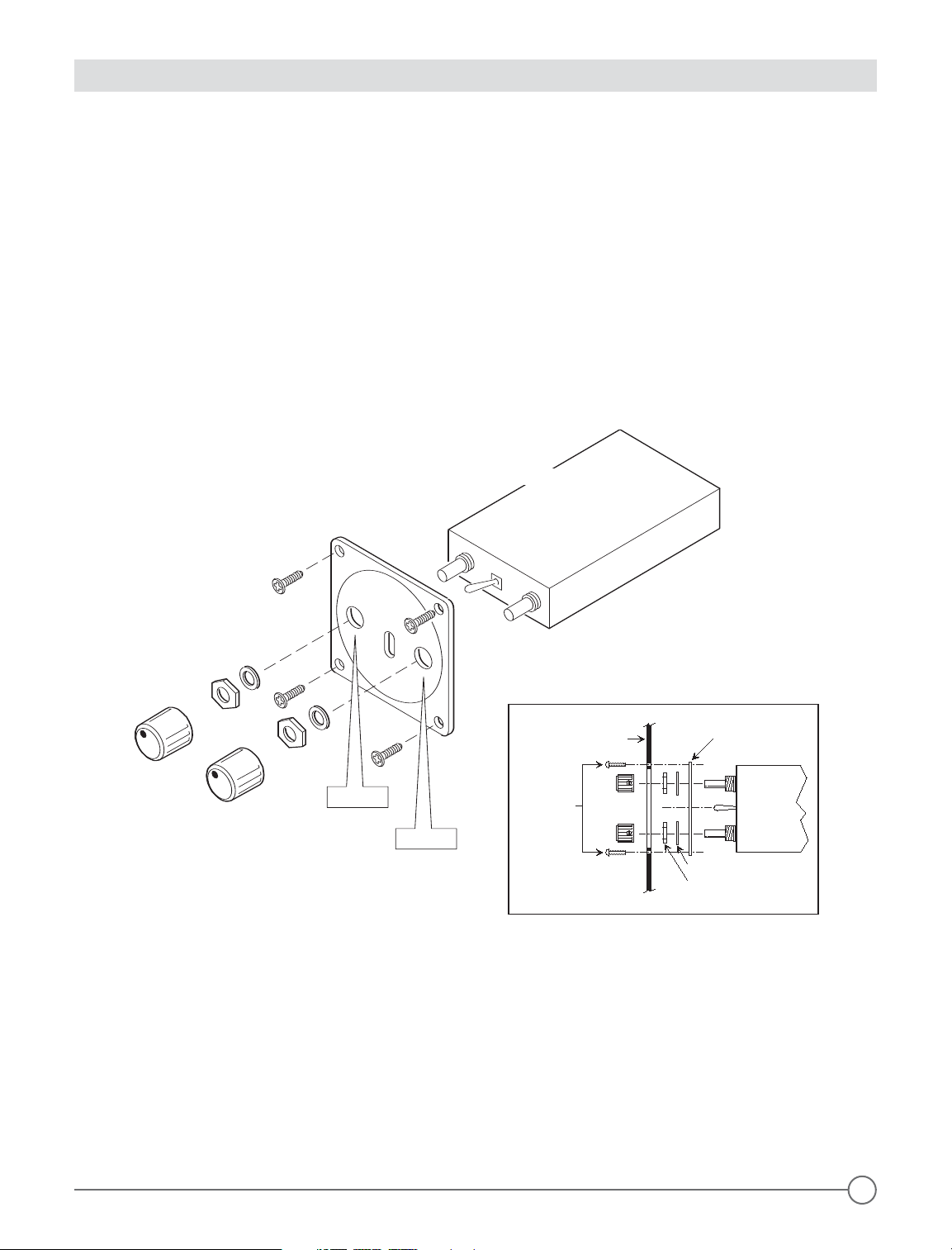
1. Secure the intercom to the large control panel using the two hex nuts and washers located on each
potentiometer control shaft (Figure 2 below).
NOTE: this is the only time when the potentiometer nuts and washers can be removed and replaced. Do not
remove or use them to secure the intercom to the aircraft panel or to the small rectangular control panel.
CAUTION: the potentiometer control shafts are easily damaged after the hex nuts have been removed.
2. Attach the intercom/control panel assembly to the aircraft panel with four 6-32 non-magnetic screws.
3. Attach the Volume and Squelch control knobs to the screws, so that both knobs point to the 7 o’clock
position when rotated completely counter-clockwise.
Large
Control
Panel
Large
Control
Panel
6-32 Non-magnetic
Screws (4)
Knobs (2)
VOLUME
SQUELCH
INTERCOM
Hex Nuts & Washers
(2 each)
Figure 2 - Large Control Panel-Exploded View
INTERCOM
AIRCRAFT
PANEL
Washers (2)
Nuts (2)
Knobs(2)
6-32
Non-Magnetic
Screws (4)
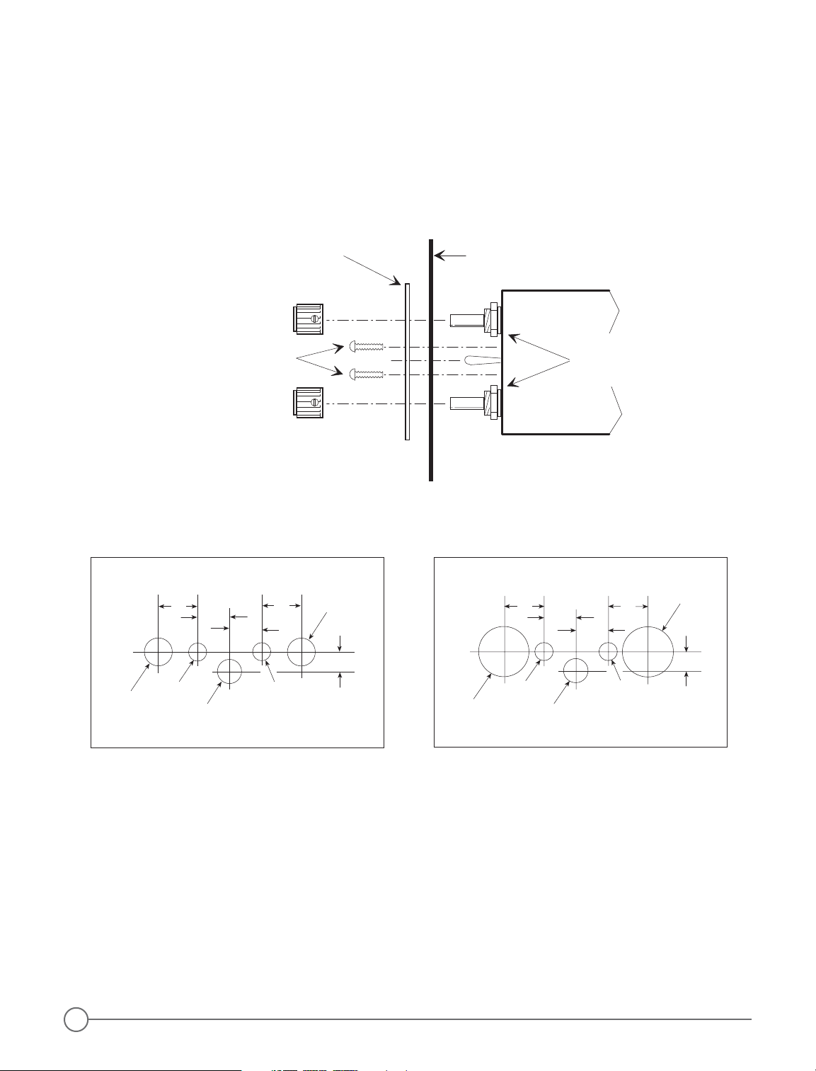
Through-panel or Under-panel Mounting
The intercom can be mounted in any 5.5 inch deep, 1.2 inch by 2.5 inch space. It can be placed either vertically or horizontally in or under the aircraft instrument panel or in any other accessible location in the aircraft.
For through-panel or under-panel mounting:
1. Leave the two potentiometer nuts in place on the intercom.
2. Place the small intercom control panel on the aircraft panel either vertically or horizontally (page 2, Figure 3),
and use one of the drill templates shown in (Figure 4, page 2) to trace the location of the holes for drilling.
• For panels less than .1 inch thick, use a 9/32 inch drill bit for the controls (use Drill Template #1 in Figure 4,
page 2,).
• For panels between .1 and .2 inches thick, use a 1/2 inch drill bit or punch to clear the potentiometer
nuts (use Drill Template #2 in Figure 4, page 2).
Figure 2 - Large Control Panel-Exploded View
1
3 Insert the intercom through the aircraft panel and the small intercom control panel with the correct side facing
outward.
4. Attach the intercom and control panel to the aircraft panel using two 4-40 by 1/2 inch mounting screws.
5. Attach the Volume and Squelch control knobs so that they both point to the 7 o’clock position when they are
rotated completely counter-clockwise.
CAUTION: to avoid contact with parts inside the intercom, do not use screws longer than 1/2 inch.
INTERCOM
AIRCRAFT
PANEL
Knob
4-40 Non-Magnetic
Screws (2)
Knob
DO NOT
Remove
These Nuts
Small
Control
Panel
.185"
.4" .4"
.3"
.3"
9/32"
9/32"
3/16"
1/4"
3/16"
.185"
.4" .4"
.3"
.3"
3/16"
1/4"
3/16"
1/2"
1/2"
Figure 4 - Drill Templates
Figure 3 - Small Intercom Faceplate Installation
Headphone and Microphone Jack Installation
The 403 and 403d intercoms can be installed as either a stereo/monaural, monaural only, or stereo only system.
With either type of installation you may leave the existing aircraft headphone and microphone jacks in place to
use as a convenient tie in point at which to connect wires 8, 17, and 21 to the radio, or you may connect the
intercom to an audio panel instead of the aircraft jacks. You can also use the existing jacks as a standby radio
connection if you remove the intercom for servicing.
With all three types of installation, you must insulate the microphone jacks from the airframe, but you may either
ground the headphone jacks to the airframe or insulate them with a separate ground wire running back to the
intercom.
NOTE: do not use the same ground wire for headphone and microphone jacks, even when the ground wires
are connected at the same location on the intercom.
2

Stereo/Monaural Jack Installation
The stereo/monaural installation is preferable because it allows stereo and monaural headsets to be used at the
same time.
To attach headphone and microphone jacks to the aircraft panel when you are installing the intercom as a
stereo/monaural system:
1. Choose an accessible location in the aircraft panel for each pair of headphone and microphone jacks (one
pair each for the pilot and co-pilot and one pair each for up to four passengers).
2. Using the stereo/mono switch plate as a template placed either horizontally or vertically, carefully mark each
stereo/mono switch and headphone jack location.
3. Drill one 1/4 inch hole in the aircraft panel for each stereo/mono switch and one 3/8 inch hole for each head
phone jack (Figure 5 below).
4. Drill one 1/2 inch hole in the aircraft panel for each microphone jack shoulder washer, preferably next to the
headphone jack.
5. Connect headphone and microphone jacks with 20-22 gauge wire (preferably 22 gauge), as shown in
(Figure 5 below) and (page 4, Figure 6 ).
6. Pass the stereo/mono switch through the aircraft panel and switch plate, and secure it using the mounting
nuts and washers provided (Figure 5 below).
7. Mount the headphone jack to the aircraft panel and switch plate, and secure it using the metal mounting nut
and washer provided.
8. Repeat steps 3 through 7 at each pre-marked headphone jack location, with the correct side of each switch
plate facing outward.
Figure 5 - Jack Mounting Diagram-Stereo/Mono
3
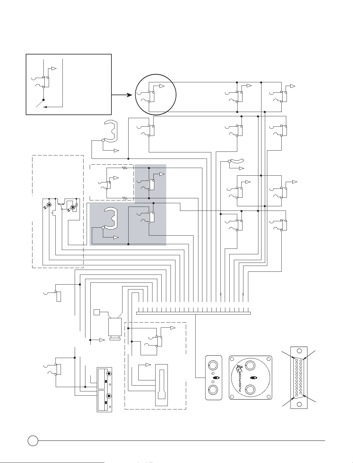
CIRCUIT
BREAKE R
PTT
7
PILOT
MIC
7
2
13
9
HDPH
PTT
6
CO-PILOT
HDPHMIC
MIC
13
HDPH HDPHMIC
MIC
13
HDPH HDPHMIC
11
13
16
14
13
PASSENGERS
11
15
4
11
11
11
13
63
POWER
12-28V
1AMP
AVIONICS GROUND
TRANSMIT KEY LINE
RECE IVE A UDIO
TRANSMIT AUDIO
MUSIC SOURCE
LEFT
RIGHT
AUX INPUT
18
19
AUX
OUT
10
12
12
12
12
12
5
PTT
5
NAVIGATOR
RED
BROWN
ORANGE
YELLOW
BLACK
24
22
23
25
AMBER
START
RECORD
PLAY
RED
47k
47k
You must install a swi tch per drawing
above at eac h headphone st ation if
you want both stereo AND monaural
capability . If a monaural headphone
is to be used , switch that s tation to
MONO mode. If you don't, t he entire
system will not operate properly a nd a
warning tone may s ound. Switches
and mounting p lates for six (6) stations
are included with the 403 and 403d
OPTIONAL
13
OPTIONAL
DCR
Control
Panel
and
Switch
Assembly
18
19
20
11721
82223
24
25
7
2
10
9
6
3145
41311
121615
ICS
Isolate
FLIGHTCO M 403
Sq Vol
Optional
SMALL Panel
MIC
HDPH
CONNECTIONS TO EXISTING
JACKS
AIRCRAFT RADIO
403
HDPH
TIP
RING
BARREL
STEREO
MONO
FLIGHTCOM 403
Intercom
ICS
Squelch
INTERCOM
Isolate
Volume
Rear view (Solder Terminal Side)
of 25 pin D-sub plu
g
(male Pins)
13
25
14
1
403d Option
intercoms.
Figure 6 - Connection Schematic - Mono Mode
NOTES: Isolate all mic jacks from airframe.
Figure 6 - Connection Schematic - Stereo Mode
4
 Loading...