

Page 1

FW3471 User’s Manual
M4068-00 1 Seyeon Tech Co., Ltd
FW3471 User’s Manual
(Product Guide)
Version 4.17
Oct. 13, 2012
Class A Digital Device (industrial & commercial environment)
This equipment has been tested and found to comply with the limits for a Class A digital device, pursuant to CE and
FCC Rules. These limits are designed to provide reasonable protection against harmful interference when the
equipment is operated in a commercial environment. This equipment generates, uses and can radiate radio frequency
energy and, if not installed and used in accordance with the instruction manual, may cause harmful interference to
radio communications. Operation of this equipment in a residential area is likely to cause harmful interference in
which case the user will be required to correct the interference at his own expense.
Page 2

FW3471 User’s Manual
M4068-00 2 Seyeon Tech Co., Ltd
FW3471 User’s Manual
Document Part Number: M4068-00
Document Version: 4.14
Revised: Oct. 13, 2012
About This Document
This document is prepared for users of FW3471 supplied by Seyeon Tech Co., Ltd. It is assumed that the
users are familiar with Microsoft Windows operating systems and Web browsers such as Internet Explorer.
It is also assumed that the users are well aware of how to install and use the network equipment such as LAN,
Hub, router, and having basic knowledge of network terminologies. If you have any questions regarding
network installations, please contact your network equipment vendor or network administrator or Internet
service providers.
For updated contents, detailed features and other applications from Seyeon Tech, please refer to the user’s
manual in CD-ROM provided with the product you purchased, or visit Seyeon Tech’s Internet homepage at
http://www.flexwatch.com/.
Copyright Notice
Copyright © 2012 Seyeon Tech Co., Ltd. All rights reserved.
No part of this document may be reproduced in any form or by any means without the prior written
permission of Seyeon Tech Co., Ltd.
Disclaimer
Seyeon Tech Co., Ltd. (Seyeon Tech) Makes no representations or warranties with respect to the contents
hereof. In addition, information contained herein is subject to change without notice. Every precaution has
been taken in the preparation of this manual, nevertheless, Seyeon Tech assumes no responsibility for errors
or omissions or any damages resulting from the use of the information contained in this document.
Trademarks
FlexWATCH® and FlexWATCH® Logo are trademarks of Seyeon Tech Co., Ltd.
Windows and Internet Explorer are a trademark of Microsoft Corporation.
All other trademarks belong to their respective owners.
Technical Support
For technical support call, email, or visit our web site.
Telephone: +82-2-2192-6840~1
Email: [email protected]
Web site: http://www.flexwatch.com or http://www.seyeon.co.kr
Page 3

FW3471 User’s Manual
M4068-00 3 Seyeon Tech Co., Ltd
Contents
1. PRODUCT OVERVIEW ........................................................................................................................... 6
1.1. FW3471 ............................................................................................................................................................................ 6
1.2. KEY FEATURES .................................................................................................................................................................... 7
1.3. TECHNICAL SPECIFICATION .............................................................................................................................................. 8
1.4. FW3471 PACKING LIST................................................................................................................................................. 10
2. PRODUCT DESCRIPTION .................................................................................................................... 11
2.1. FW3471 FRONT VIEW .................................................................................................................................................. 11
2.2. FW3471 REAR VIEW ..................................................................................................................................................... 12
2.2.1. CTL Port Description ........................................................................................................................................... 13
2.2.2. RS-232 Interface .................................................................................................................................................... 13
2.2.3. RS-485 Connection .............................................................................................................................................. 13
2.2.4. DI Connection......................................................................................................................................................... 13
2.2.5. DO Connection ...................................................................................................................................................... 13
3. FW3471 INSTALLATION AND BASIC SETUP................................................................................... 14
3.1. BEFORE INSTALLATION ................................................................................................................................................... 14
3.2. FACTORY DEFAULT SETTINGS........................................................................................................................................ 14
3.3. INSTALLING FW3471 ..................................................................................................................................................... 14
4. ADMIN MENU ...................................................................................................................................... 15
4.1. ENTERING ADMIN MENU .............................................................................................................................................. 15
4.2. ADMIN MENU STRUCTURE ........................................................................................................................................... 16
5. QUICK CONFIGURATION .................................................................................................................... 17
5.1. STEP 1. SERVER NAME SETUP....................................................................................................................................... 17
5.2. STEP 2. LOCAL DATE & TIME CONFIGURATION........................................................................................................ 17
Page 4

FW3471 User’s Manual
M4068-00 4 Seyeon Tech Co., Ltd
5.3. STEP 3. NETWORK CONFIGURATION ........................................................................................................................... 17
5.4. STEP 4. IP-CCTV DNS ™ SETUP ............................................................................................................................... 17
5.5. STEP 6. RECORDING COFIGURATION ........................................................................................................................... 18
5.6. FINISH ............................................................................................................................................................................... 18
6. SYSTEM CONFIGURATION ................................................................................................................. 18
6.1. SERVER NAME SETUP ..................................................................................................................................................... 18
6.2. DATE & TIME .................................................................................................................................................................. 19
6.3. ADMIN. PASSWORD ....................................................................................................................................................... 19
6.4. ACCESS CONTROL........................................................................................................................................................... 20
6.5. USER REGISTRATION ....................................................................................................................................................... 20
6.5.1. Add .............................................................................................................................................................................. 20
6.5.2. Edit ............................................................................................................................................................................... 20
6.5.3. Delete ......................................................................................................................................................................... 21
7. NETWORK CONFIGURATION ............................................................................................................ 21
7.1. NETWORK CONFIGURATION.......................................................................................................................................... 22
7.1.1. Static IP Configuration ....................................................................................................................................... 22
7.1.2. DHCP Client Configuration............................................................................................................................... 22
7.1.3. PPPoE Configuration ........................................................................................................................................... 22
7.2. NETWORK PORTS ............................................................................................................................................................ 23
7.3. BANDWIDTH CONTROL .................................................................................................................................................. 24
7.4. VIEW NETWORK STATUS ................................................................................................................................................ 24
7.5. NETWORK STATUS NOTIFY ............................................................................................................................................ 25
7.6. IP-CCTV DNS™ SETUP ............................................................................................................................................... 26
7.7. PORT FORWARDING & UPNP ..................................................................................................................................... 27
7.8. RTP/RTSP ....................................................................................................................................................................... 28
7.9. SNMP SETUP .................................................................................................................................................................. 29
Page 5

FW3471 User’s Manual
M4068-00 5 Seyeon Tech Co., Ltd
8. DEVICE CONFIGURATION .................................................................................................................. 30
8.1. SERIAL PORTS CONFIGURATION ................................................................................................................................... 30
8.1.1. Serial Input Mode ................................................................................................................................................. 30
8.1.2. Serial Output Mode ............................................................................................................................................. 31
8.1.3. Transparent Mode ................................................................................................................................................ 32
9. ADVANCED CONFIGURATION .......................................................................................................... 32
9.1. ADVANCED SERVICES ..................................................................................................................................................... 33
9.1.1. E-mail Service Configuration ........................................................................................................................... 34
9.1.2. FTP(Buffered)Service Configuration .............................................................................................................. 37
9.1.3. FTP(Periodic) Service Configuration ............................................................................................................. 39
FTP(Periodic) Service Configuration for each Camera ........................................................................................ 39
9.1.4. Sensor Notification............................................................................................................................................... 40
9.1.5. Alarm Output Service Configuration ........................................................................................................... 42
10. RECORDING CONFIGURATION...................................................................................................... 43
11. UTILITIES ........................................................................................................................................... 43
11.1. SYSTEM LOG .................................................................................................................................................................... 44
11.2. SAVE CONFIGURATION .................................................................................................................................................. 44
11.3. REBOOT ............................................................................................................................................................................. 44
11.4. FACTORY DEFAULT .......................................................................................................................................................... 45
11.5. SYSTEM UPDATE .............................................................................................................................................................. 45
11.5.1. Update by Item ................................................................................................................................................... 46
Page 6
FW3471 User’s Manual
M4068-00 6 Seyeon Tech Co., Ltd
1. Product Overview
1.1. FW3471
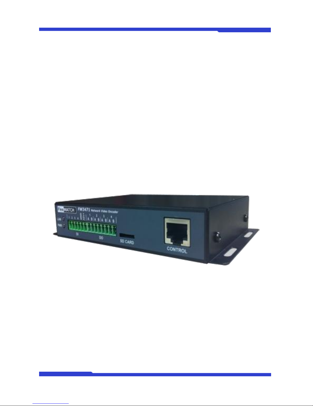
FlexWATCH® 3471 is 4ch network video server which transmits digital images captured by Analog
CCD camera over IP(Internet Protocol) network.
It can transmit up to 30fps@D1 over the existing network. You can monitor video of FW3471 through
web browser(ie. MS Internet Explorer), if FW3471 is connected to network. FW3471 supports video
compression both MJPEG and H.264 simultaneously so that user can choose appropriate video compression
for the purpose. For both MJPEG and H.264, FW1174 provides 6 levels of video quality.
FW3471 server is state-of-the art device and leads new generation of monitoring and security solution.
Picture 1 : FW3471
Page 7

FW3471 User’s Manual
M4068-00 7 Seyeon Tech Co., Ltd
1.2. Key Features
Standalone device with a built-in web server
10M/100M/1000M Auto-Sensing Ethernet
Configuration and control device through Web browser
Max 120 fps transmission speed on TCP/IP network
Compressed audio transmission for each of 4 channels
Audio decoding for one channel
Support Dynamic IP network by IPCCTVDNS Server
Support various PTZ (Pan/Tilt/Zoom) devices
Support Sensor Input, Digital Output
Support Transparent Mode
Encryption function by user authentication
Image transmission via FTP and Email
Provide 4-Channel analog quad outputs
Page 8

FW3471 User’s Manual
M4068-00 8 Seyeon Tech Co., Ltd
1.3. Technical Specification
Hardware
32bit Embedded CPU
Flash 8Mbytes /SDRAM: 128Mbytes
Linux version 2.6.24.4 operating system
Battery backed up real-time clock
Video
compression
MJPEG
H.264
Resolution
NTSC: 704x480,704x240,352x240,176x112
PAL: 704x576,704x288,352x288,176x144
Frame rate
(each channel)
Up to 120 fps@D1
Video Streaming
MJPEG and H.264 Dual Streaming (Simultaneously)
Controllable frame rate and bandwidth
Image setting
Compression levels: 6 (MJPEG/H.264)
Color: color, black & white
Transmission
Performance(1000Base-T / LAN)
Trans: Up to 120fps(NTSC)/100fps (PAL)
when 4channels at D1
Voice
4bit G.723, Sampling rates 8KHz Mono
Audio 4ch in & 1ch out
LAN interface
10/100/1000BaseT Ethernet auto sensing
Alarm I/O Interface
4x1 Photo-coupled inputs and 4 Relay output
Video Input
4 Channel Composite Video Input
Quad Output
1 Channel Quad Composite Video Output
Serial Interface
COM Port: RS-232
AUX Port: RS-485/RS-422
COM ports for console, serial input/output device and AUX ports for PTZ or
other RS485/422 device
Max Baudrate: 115200 bit/s
Security features
Multi user level protection for camera access, PTZ, Alarm I/O
Advanced Service
Up to 5.6M memory for Pre/Post alarm buffer e-mail, FTP, IP notification,
Alarm Notification to e-mail, CGI Call by event or schedule
Built-in Motion detections
Accuracy: 12x12=144 blocks
Motion Sensitivity : -100 ~ 100 : 100 is hypersensitive
PTZ & UART Control
Support
PTZ and UART device control through serial port (RS-232/RS-485) (Support
protocols from Pelco “P”& “D”protocol, Vicon V1311RB, Samsung PTZ,
Honeywell PTZ and X10 Epson Printer)
Others
Time stamp on Video
Transmit External data(ex. POS) transfer with Video
IP notification by e-mail
Management
Configurable by serial, web or telnet
Remote system update via telnet, FTP OR web browser.
Page 9

FW3471 User’s Manual
M4068-00 9 Seyeon Tech Co., Ltd
Developer support
Provides HTTP CGI API
ActiveX control development kit
PWR Supply
SMPS
Input: 100~240VAC, 1.5A
Output: DC 12 Volt, 3 A, SMPS
PWR Consumption
DC 12Volt
Max or Peak: 0.8 A
Normal : 0.7 A
Operating Environment
Temperature : 32° ~ 122°F (0° ~ 50°C)
Humidity : 20 ~ 80% RH(non-condensing)
Miscellaneous
Work with Smart NVR(CMS software)
Dynamic IP support through IPCCTVDNS Server
Users
128 simultaneous users
Installation, management
and maintenance
Installation CD and web-based configuration
Firmware upgrades over HTTP, telnet or FTP, firmware available at homepage
Video access from Web
browser
Video access from Web browser
Minimum Web browsing
requirements
Pentium 4, 2 GHz, 2GB(RAM) or higher
Video Card: 256MB RAM, 1024x768 resolution or higher
100Mbps Network Adaptor or faster
Windows XP Pro or later
Internet Explorer 6.x or later
System integration support
Powerful API for software integration available at http://www.flexwatch.com,
including Simple Viewer API, FlexWATCH Control SDK, event trigger data in
video stream, embedded scripting and access to serial port peripherals over
HTTP/TCP
User can be installed user program daemon for event notification or sending
image.
Embedded operating system: Linux 2.6
Supported protocols
HTTP, TCP/IP, FTP, Telnet, RARP, PPPoE, PAP, CHAP, DHCP, NTP, SMTP
client
Approvals
KCC
FCC : Class A
CE : Class A
RoHS
Dimensions (HxWxD) and
weight
140(W) x 215(D) x 44(H) (in mm)
About 0.80kg without power supply.
Table 1 : FW3471 Data Sheet
Page 10
FW3471 User’s Manual
M4068-00 10 Seyeon Tech Co., Ltd
1.4. FW3471 Packing List
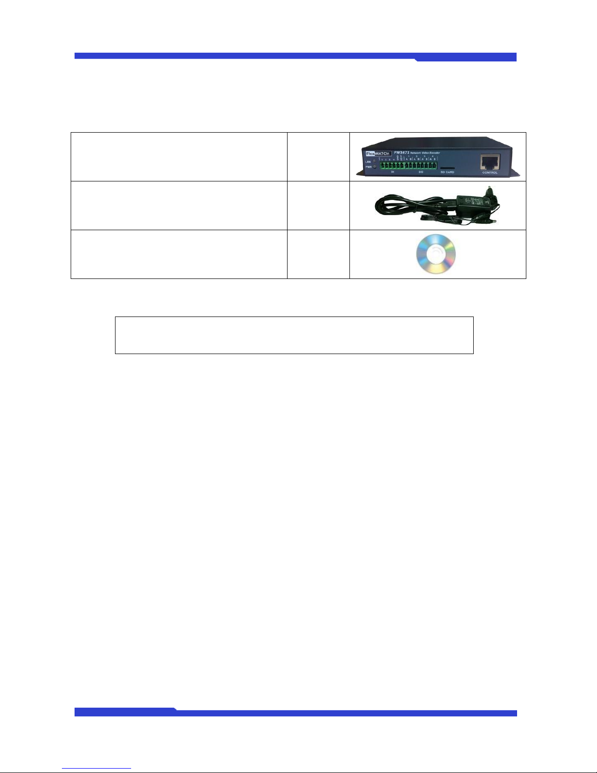
FW3471
1 EA
Power Supply
(Power Cable & SMPS DC12V 3A Adapter)
1 EA
CD (User’s Manual, IP Installer and etc)
1 EA
Table 2 : FW3471 Packing List
Note: Please make sure all the listed items are included in the package. For any
missing items, please contact your local distributor.
Page 11
FW3471 User’s Manual
M4068-00 11 Seyeon Tech Co., Ltd
2. Product Description
2.1. FW3471 Front View
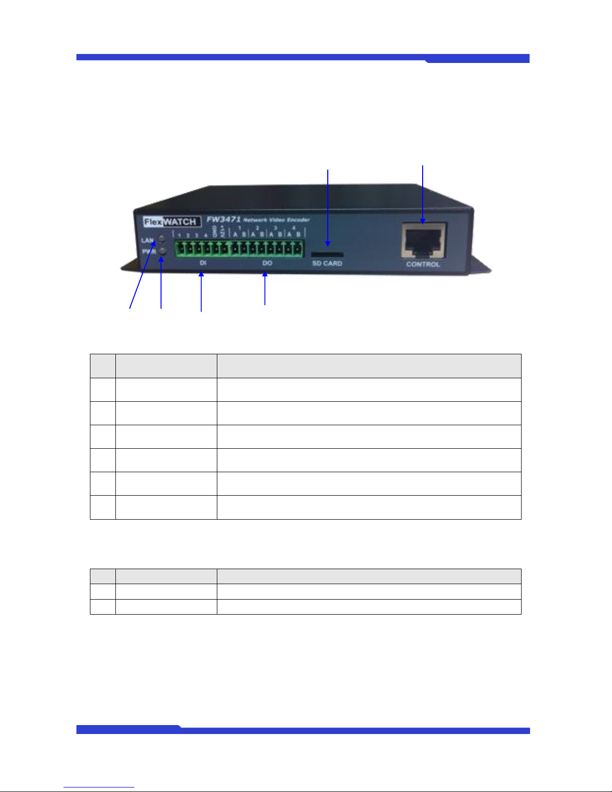
Picture 2 : FW3471 Front View
Picture 3 : Enlarged Front LED
Name
Description
A
LAN LINK LED
Indicates the connection status of LAN connector. It goes green when a
physical connection is properly made to the LAN port.
B
POWER LED
This red LED is lit during FW3471 is powered on.
C
DI
Sensor/Contact Input Port
D
DO
Beacon/Alarm Output Port
E
SD CARD
F
CONTROL
CTL Port (RS-485, RS-232, DI, DO)
Table 3 : FW3471 Front Panel
Beep Sound Description
Name
Description
1
Power ON
One short beep if boot-up is started normally.
2
System Ready
Two short beeps if boot-up is finished normally.
Table 4 : FW3471 Beep Sound
E
B
D
Page 12
FW3471 User’s Manual
M4068-00 12 Seyeon Tech Co., Ltd
2.2. FW3471 Rear View
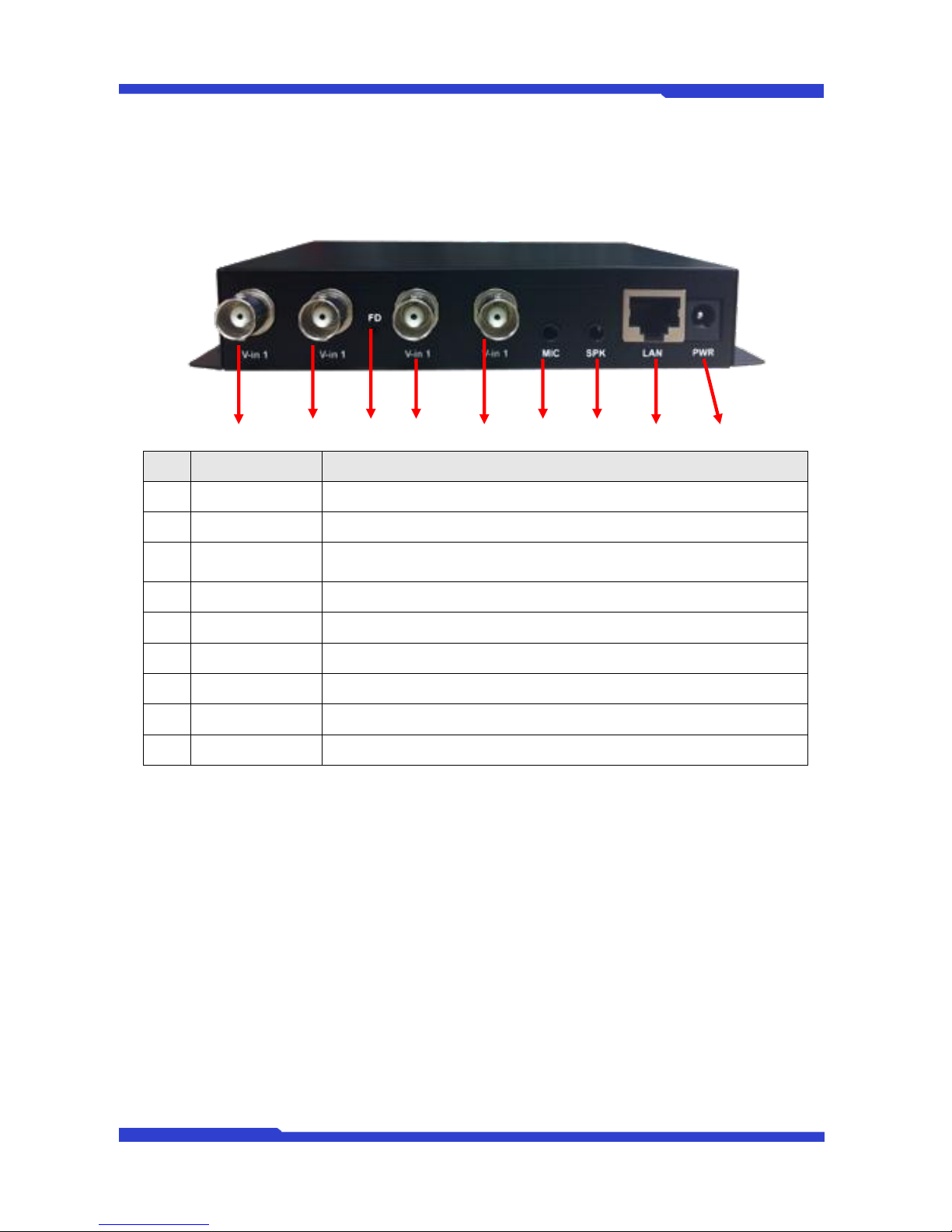
Picture 4 : FW3471 Rear View
A B C D E F G H I
이름
설명
A
Video In 1
BNC cable port for Video input of number 1 camera of Module 1.
B
Video In 1
BNC connector for Camera 2
C
FD
Beep one time (0.5 sec) after three seconds and then beep three times shortly
after another three seconds.
D
Video In 1
E Video In 1
F
MIC
Audio Input Port
G
SPK
Audio Output Port
H
LAN
RJ-45 Network Connector
I
Power
DC 12V 3A
Table 5 : FW3471 Rear Panel
Page 13
FW3471 User’s Manual
M4068-00 13 Seyeon Tech Co., Ltd
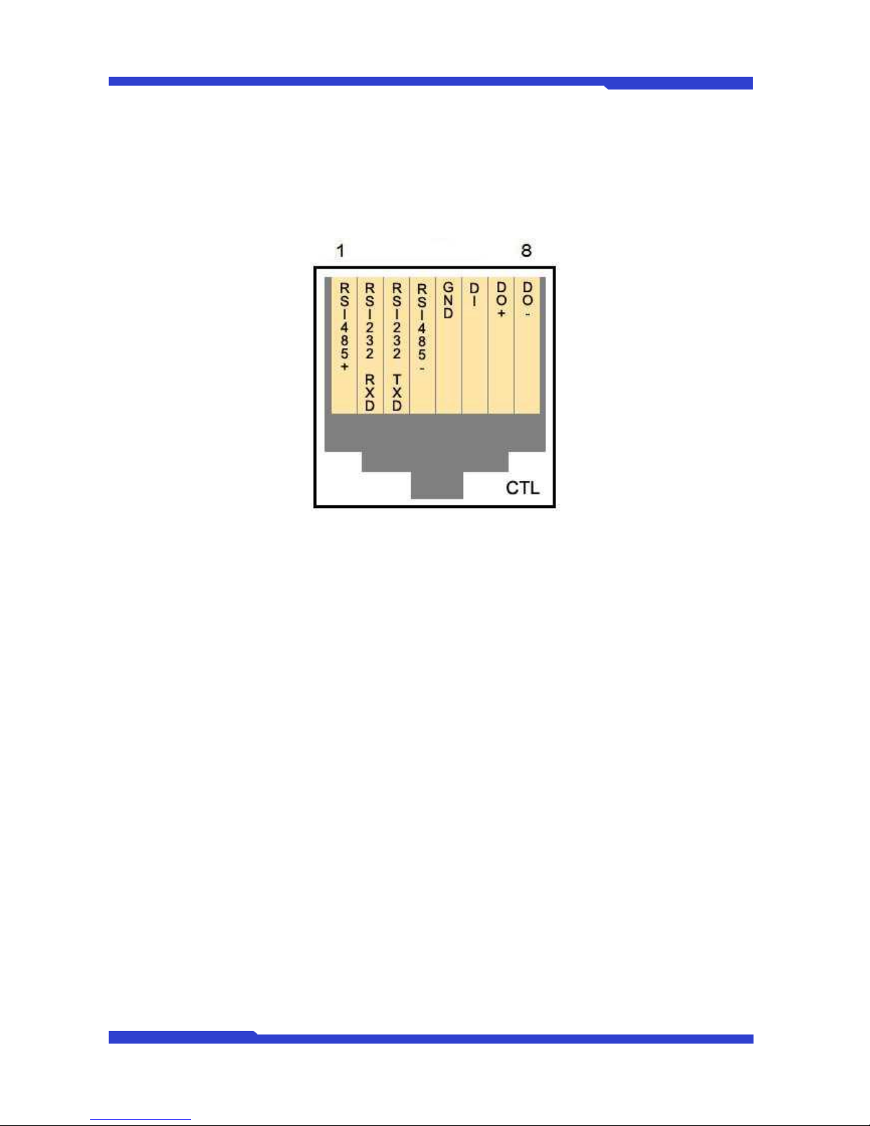
2.2.1. CTL Port Description
The picture below shows how to wire CTL port connector pins for Sensor Input (DI, GND), Relay Out (DO+,
DO-), RS-485 (+, -) and RS-232 (RXD, TXD, GND) signals. When installing, each signal should be wired to the
correct pin as shown in the picture.
Picture 5 : CTL Port Description
2.2.2. RS-232 Interface
RS-232 Port is provided for a connection with external devices such as water level sensor, speed sensor, or
etc. To make an interface with those external devices, please contact Seyeon Tech for details and techniques
about the necessary protocols. GND pin for RS-232 is shared with Sensor Input GND. It is common to use only
RXD, TXD, and GND signals for RS-232 in real world applications. For this reason, other signals of RS-232
standard are not provided here. If FW-1173-DS needs to be connected other network devices through RS-232,
then RXD and TXD pin may need to be crosswired.
2.2.3. RS-485 Connection
RS-485 port is a serial interface for communication with external devices, which is functionally similar to RS-
232. However, thanks to its physical characteristic and reliability, RS-485 makes it possible for the use of very
long signal lines, and very high data transmission rate. In FW-1173-DS, you can use RS-485 interface port for
controlling PTZ, multiplexers, access control boxes, X10 protocol peripherals, and etc. To make an interface
with those external devices, please connect Seyeon Tech for details and techniques about the necessary
protocols.
2.2.4. DI Connection
DI(Digital In) is a Sensor Input port which can be used for acquiring input signal from an external device such
assensors, switches, and etc. FW-1173-DS can recognize the input state if DI+ port is connected to GND or
left unconnected. It can be selected which of NC or NO condition to be used.
2.2.5. DO Connection
DO (Digital Out) is an Alarm Output port which can be used for activating door opener/closers, sirens,
emergency beacons, and etc. DO port is on Open-Collector basis, and driving current must not exceed 100mA
at DC 5 to 12Vrange. FW-1173-DS activates DO port by turning on or off the Open-Collector driver.
Page 14

FW3471 User’s Manual
M4068-00 14 Seyeon Tech Co., Ltd
3. FW3471 Installation and Basic Setup
3.1. Before Installation
Read carefully User's Manual.
Check User’s Network (IP Address, Network Mask and default gateway)
Secure IP address for FW3471.
3.2. Factory Default Settings
The following table shows the factory default condition. Please refer to this when you need to change the
values on admin menu.
Factory Default
Admin ID
root
Admin password
root
IP address
10.20.30.40
Network mask
255.255.255.0
Gateway
10.20.30.1
Table 5 : Factory Default
Note: Factory default Admin ID and Password are all lower case letters. You can change the
password with Capital letters.
3.3. Installing FW3471
For installation of FW3471, please follow the steps below.
1. Place the CCTV cameras in place and connect power supplies.
2. Connect the video output ports of analog CCTV cameras to the video-in ports of FW3471.
3. Connect the FW3471 to the Internet cable through the LAN port.
4. Connect the power supply of FW3471.
After that, you need to follow the steps below.
Network Configuration: Refer to “IP Installer User’s Manual”
Camera Configuration: Refer to “FlexWATCH Admin Menu User’s Manual”
Service Configuration: Refer to “FlexWATCH Admin Menu User’s Manual”
Page 15
FW3471 User’s Manual
M4068-00 15 Seyeon Tech Co., Ltd
4. Admin Menu
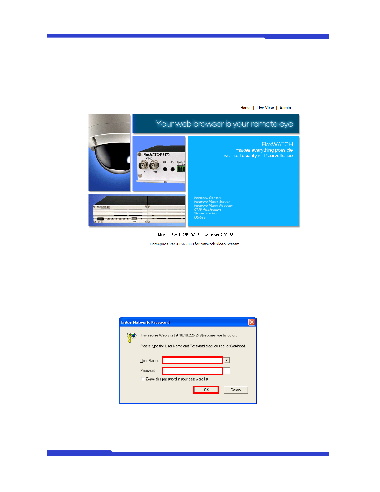
After connecting to a FlexWATCH™ server on the web browser, you’ll find the web page as shown
below. The rightmost item of the menu is Admin, where you can set up the most of features in the
FlexWATCH™ Server you’re connecting to.
4.1. Entering Admin Menu
Click “Admin” item of the menu, then you’ll see a login window. In the login window, enter “root” for
both ID and password as they are the factory defaults. Press Enter key or click “OK” button. Once logged in,
you can change the password to a new one.
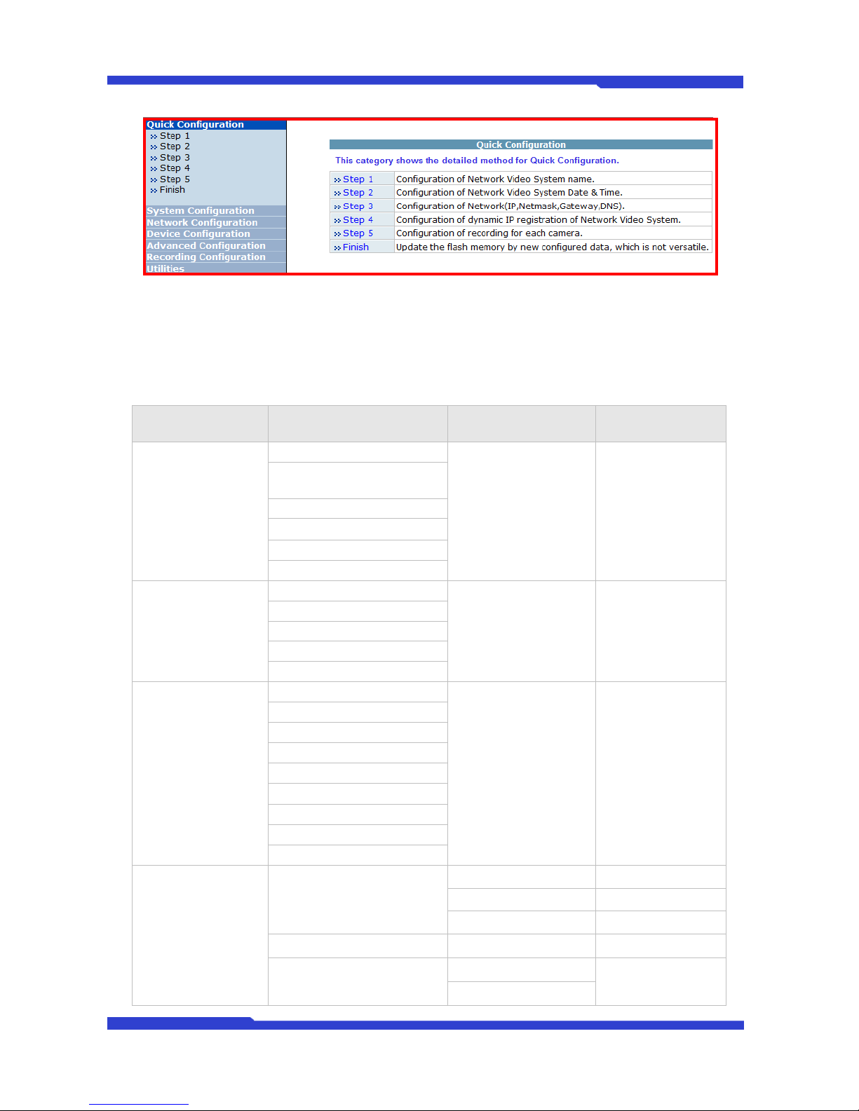
Now the Admin Menu will be displayed as shown below. This will guide you to the top level menu items,
which are Quick, System, Network, Device, Advanced, Recofding and Utilities. Clicking any of these top level
menu items will display submenu items and brief descriptions.
Page 16
FW3471 User’s Manual
M4068-00 16 Seyeon Tech Co., Ltd
4.2. Admin Menu Structure
The following table shows the hierarchy of the Admin menu structure that we’re going to deal with in this
manual.
Category
Main Menu
Level 1 Sub-Menu
Level 2 Sub-Menu
Quick Configuration
Server Name Setup
n/a
n/a
Local Date & Time
Configuration
Network Configuration
IP-CCTV DNS™ Setup
Recording Configuration
Finish
System
configuration
Server Name
n/a
n/a
Date & Time
Admin. Password
Acess Control
User Registration
Network
Configuration
Network Configuration
n/a
n/a
Network Ports
Bandwidth Control
View Network Status
Network Status Notify
IP-CCTV DNS™
Port Forwarding & UPnP
RTP/RTSP
SNMP
Device Configuration
Serial Ports
Serial Input Mode
n/a
Serial Output Mode
n/a
Transparent Mode
PTZ Mode
Privacy Zone
Camera 1~4
n/a
Camera & Motion
DI/DO
n/a
DI Status/DO Control
Page 17

FW3471 User’s Manual
M4068-00 17 Seyeon Tech Co., Ltd
Advanced
Configuration
Advanced Services
E-mail
Camera 1~4
FTP(Buffered)
FTP(Periodic)
Sensor Notification
Input 1~4
Alarm Output
Output 1~4
Recording
Configuration
SD Configuration
SD Status & Format
n/a
SD Information
n/a
Recording Configuration
Built-in Module 0
Camera 1~4
Recording Profile
n/a
n/a
Recording Mode
SD Status Report
Clear Recording Config.
Delete Recorded Data
Utilities
System Log
n/a
n/a
Save Configuratioin
Reboot
Factory Default
System Update
5. Quick Configuration
5.1. Step 1. Server Name Setup
Click Server Name on Quick Configuration menu, then Server Name Setup windows will be displayed.
See the section 6.1 Server Name Setup in page 18 to see how to change the server name.
5.2. Step 2. Local Date & Time Configuration
Click Date & Time on System Configuration menu, then Local Date & Time Configuration window will be
displayed. See the section 6.2 Local Date & Time Configuration in page 18 to see how to set up.
5.3. Step 3. Network Configuration
To make a connection to the Internet, it is required to figure out the type of the Internet service you’re
using. See the section 7.1 Network Configuration in page 21 to see how to set up.
5.4. Step 4. IP-CCTV DNS ™ Setup
When FlexWATCH Server is used in a Dynamic IP environment, it is required to utilize IP-CCTV DNS
feature. See the section 7.6 IP-CCTV DNS Setup in page 27 to see how to set up.
Page 18
FW3471 User’s Manual
M4068-00 18 Seyeon Tech Co., Ltd
5.5. Step 6. Recording Cofiguration
Each camera can be configured for recording option in this section. See the section 6.7 Recording
configuration for FW5050/5071/5450/5850/5870 NVR series in page 45 for detail.
5.6. Finish
You need to save all the changes to the Flash Memory after finishing the configuration. The changes
made to FlexWATCH Server will be permanent by this step. Click Finish on Quick Configuration menu.
Click Save Configuration button. This will write the new settings to the system’s flash memory. If you don’t
want to save them, click Back button.
6. System Configuration
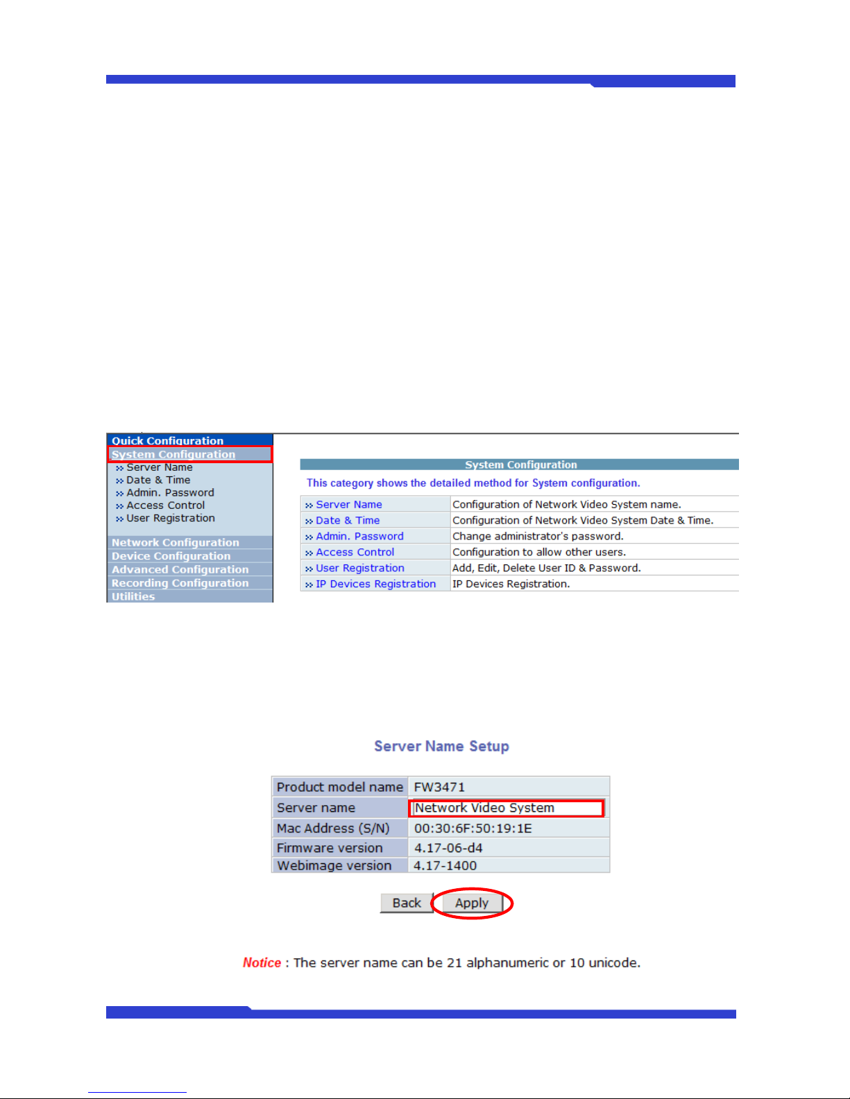
When you click on “System Configuration” item on Admin Menu, the following sub menu will be
displayed.
6.1. Server Name Setup
Click Step 1 on Quick Configuration, then the following will be displayed and you will find out the
system information such as model name of the FlexWATCH™ Server, server name, MAC address (serial
number), firmware version, and Web image version.
Page 19
FW3471 User’s Manual
M4068-00 19 Seyeon Tech Co., Ltd
As an administrator, you can change the server name, but other values are not allowed to change. To
change the server name, enter a new server name in the Server Name filed. You may use up to 21
alphanumeric or up to 10 Unicode characters. Tab or any other special characters are not allowed. Click
“Apply” button to save the setting and it will take effect immediately.
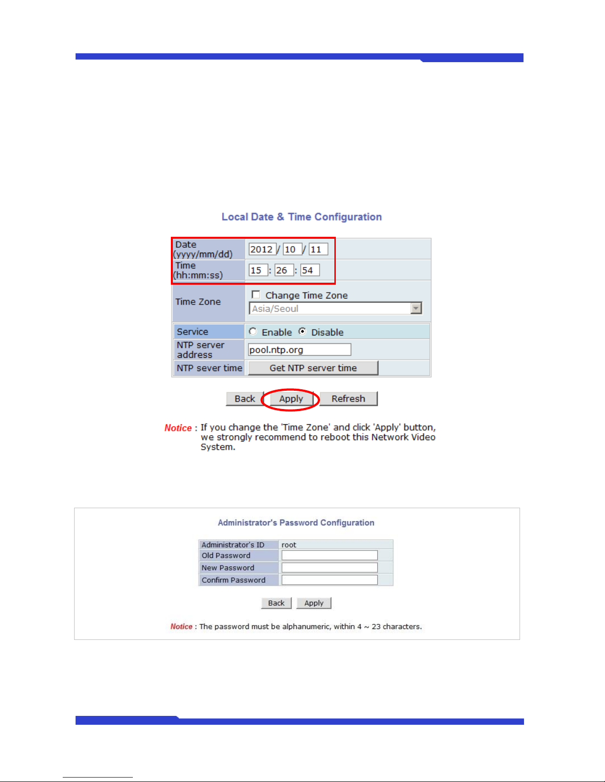
6.2. Date & Time
Click Step 2 on Quick Configuration, then the following will be displayed and you will set up the Local
Date & Time and Time Zone and apply service for setting up NTP server address and time.
6.3. Admin. Password
To change the password for the administrator, click Admin Password on System Configuration menu.
Default ID for admin account is fixed as “root” and not allowed to change. In Old Password field, enter
the current password. In both New Password and Confirm Password fields, enter the same new password.
The password must be between 4 and 23 alphanumeric letters. Click Apply button to put it into effect.
Because you have replaced the password with a new one, the existing network connection made with
Page 20

FW3471 User’s Manual
M4068-00 20 Seyeon Tech Co., Ltd
old password to FlexWATCH Server is lost now. You will have to reconnect to the FlexWATCH server using
new password.
6.4. Access Control
Click Access Control on System Configuration menu. The following windows will be displayed.
From the Access Permission window, select either one you would like to use. Click Apply button to
save the change.
Full Access: Any user can access the server and use all the features without limit.
Limited Access: Only registered users can access the server and have limited privileges.
6.5. User Registration
6.5.1. Add
When Add is selected, you can add users and define their passwords, names, and access permission levels
respectively. To add a user, click User Registration on System Configuration menu. Next, select Add, then
the User Registration (Add) selection screen will be displayed.
Enter a user ID, which must consist of up to 23 alphanumeric characters. In both Password and Confirm
Password fields, enter the identical password respectively. The password must be between 4 and 23
alphanumeric characters. In Name filed, enter the user’s name that must be up to 31 alphanumeric or 15
Unicode characters. Now select one of the four items from System Resource Access Permission, which
defines the permission level for registered users to the FlexWATCH server.
All Channels Access: User can use all the features except for Configuration in Admin Page.
General Access (only live viewing access): User can use only use Live View feature.
No Access: User is not permitted of any of the features.
Selective Access: User is allowed to use only the selected features. With this item selected, user can
now configure the details under the menu. FlexWATCH Server can have multiple VS modules
registered in it. When user ticks on any of Enable checkboxes, other fields in that row are enabled to
select.
VS Module ID: The registered user can select VS Modules that are available. (VS Module is a
network device that has been registered in FlexWATCH® Server)
Camera No.: Among the cameras of VS Module, select one to set up. (between 1 and 4)
Alarm Control: Determine if Alarm control is to be allowed.
PTZ Control: Determine if PTZ Control is to be allowed.
Audio Control: Determine if Audio Control is to be allowed.
Playback: Determine if searching can be done by recording conditions. After finishing the registrati-
on process, click Apply button to add the user.
6.5.2. Edit
To edit a user account, select Edit. In this part, you can modify the existing user’s name, password,
and access permission. User ID is not allowed to change. Once selecting a user ID for edit, the usage
is the same as in Add section.
To see existing users, click Select UserId, and select a user to be edited. Then change the password,
name, or access permission, and click Apply button to save the setting. Setup of Access Permission
can be done the same way as in Add section.
Page 21
FW3471 User’s Manual
M4068-00 21 Seyeon Tech Co., Ltd
6.5.3. Delete
To delete an existing user, select Delete.
From the list of the users, select a user to delete. Click Delete button to confirm the deletion.
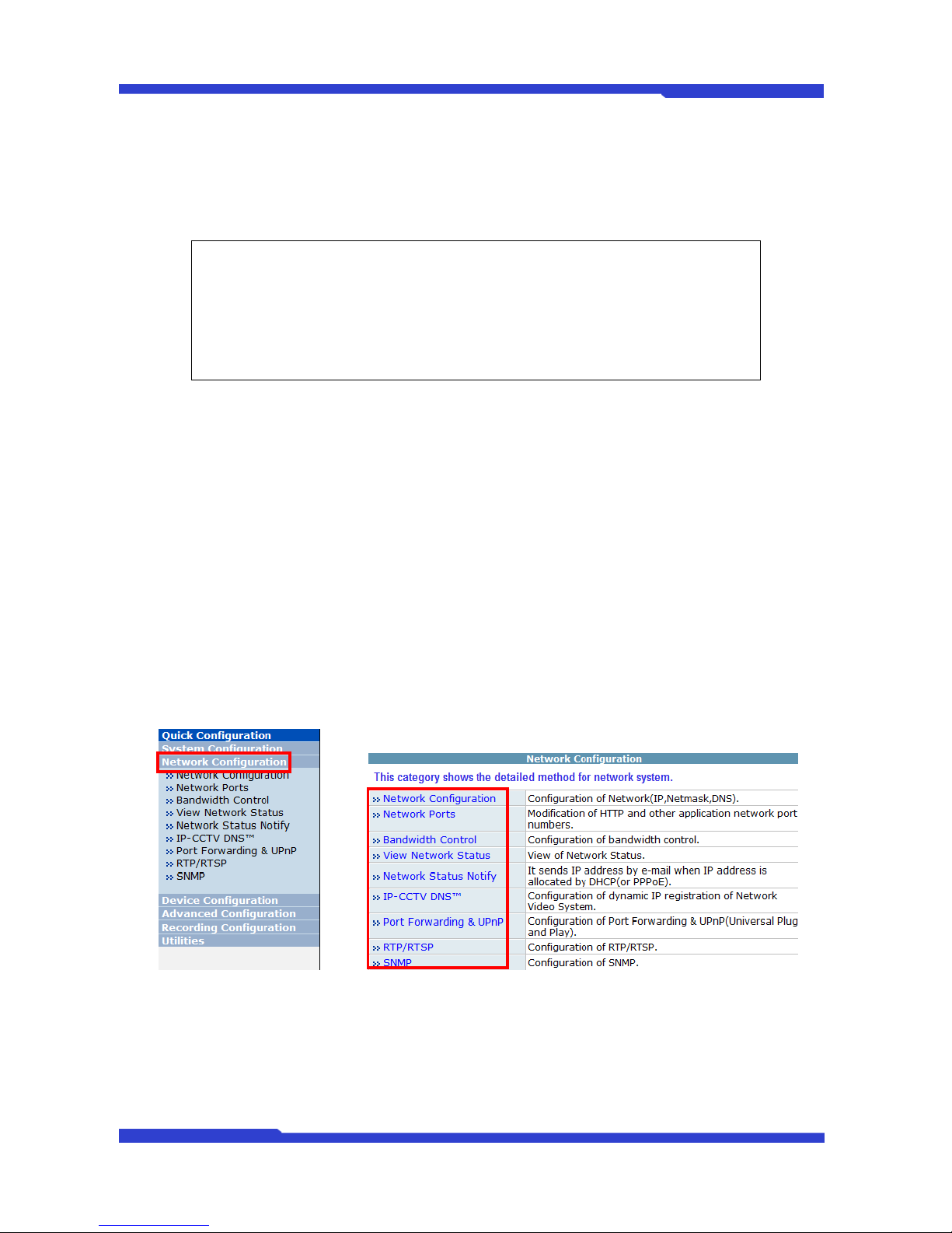
7. Network Configuration
Configuration the network is dependent on how an IP address is assigned in Ethernet-based
environment, which is static IP, dynamic IP (DHCP). For wireless LAN, additional configuration is necessary to
have a connection with wireless AP.
In the case of wireless models, users have to choose between wired or wireless connection. In other
words, both connections can’t be used at the same time. The way how to choose one of them is whether wired
LAN cable is plugged into the product. When LAN cable is plugged in for longer than 5 seconds, the wired LAN
is activated for data transmission. If LAN cable is unplugged more than 5secconds, wireless LAN is activated
instead. If DHCP Client is selected by user, wired LAN will be activated regardless of condition of LAN cable.
For network configuration, select Network configuration from Admin page.
To make a connection to the Internet, it is required to figure out the type of the Internet service you’re
using. Depending on the service type, the network configuration can be in any of Static IP, DHCP Client. You
need to set up the FlexWATCH™ Server according to your network type.
Note: If the HTTP port number is changed to other value than default (80), make sure
the new HTTP port number goes together with the FlexWATCH™ Server's
Internet address. For example, when FlexWATCH
™
’'s IP address is
192.168.1.00 and set the HTTP port to 8080, you will have to enter
http://192.168.1.100:8080 to connect to the server.
Page 22
FW3471 User’s Manual
M4068-00 22 Seyeon Tech Co., Ltd
7.1. Network Configuration
7.1.1. Static IP Configuration
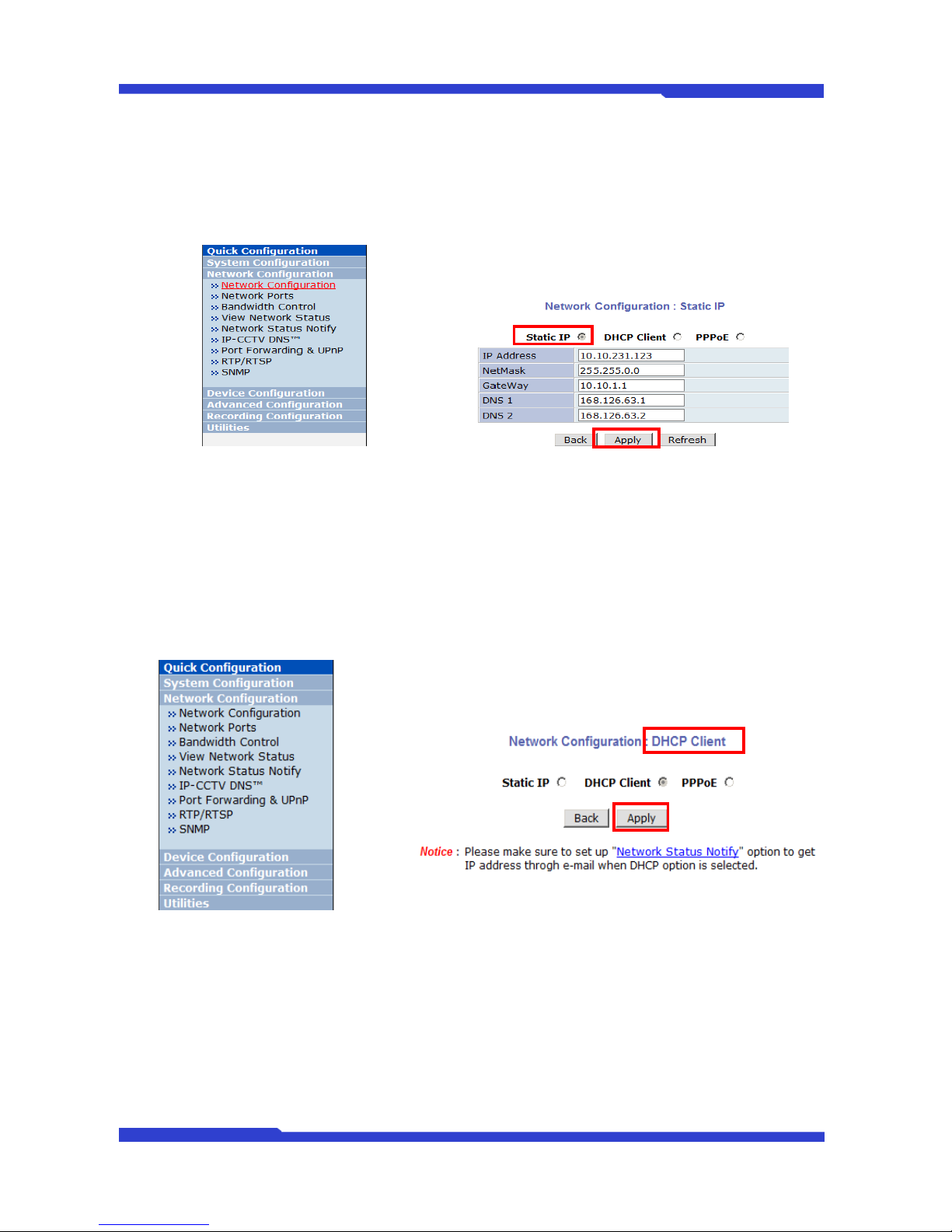
Selecting Network Configuration under Network configuration will show variables. Below picture is for
products without wireless LAN.
For static IP, select static IP and input values for IP address, NetMask, Gateway, DNS1, DNS2 and click
apply for saving settings. After “Apply”, program will ask closing web browser for updates, which will take
20~30 seconds. If “Back” button is pushed while configuration, all values will be discarded. If “Refresh”
button is pushed, the program will load previous values.
7.1.2. DHCP Client Configuration
For DHCP, DHCP server must exist in the network environment. Select DHCP Client from Network
Configuration, click “Apply”.
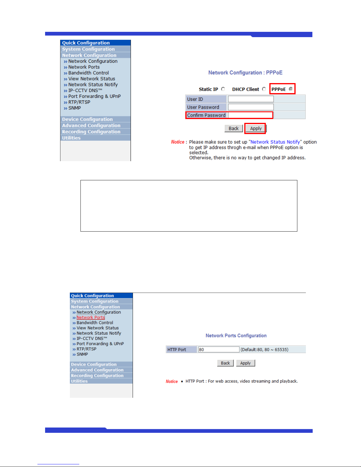
7.1.3. PPPoE Configuration
Page 23
FW3471 User’s Manual
M4068-00 23 Seyeon Tech Co., Ltd
7.2. Network Ports
In this configuration, you set up the HTTP port for FlexWATCH™ Server to communicate with the Client
PC. HTTP Port is the network port that is used when a Client PC connects to the FlexWATCH™ Server’s
Web page. It can be assigned between 80 and 65535 and the default value is 80.
Note: If the HTTP port number is changed to other value than default (80), make sure
the new HTTP port number goes together with the FlexWATCH Server's
Internet address. For example, when FlexWATCH's IP address is 192.168.1.00
and set the HTTP port to 8080, you will have to enter
http://192.168.1.100:8080 to connect to the server.
Page 24
FW3471 User’s Manual
M4068-00 24 Seyeon Tech Co., Ltd
7.3. Bandwidth Control
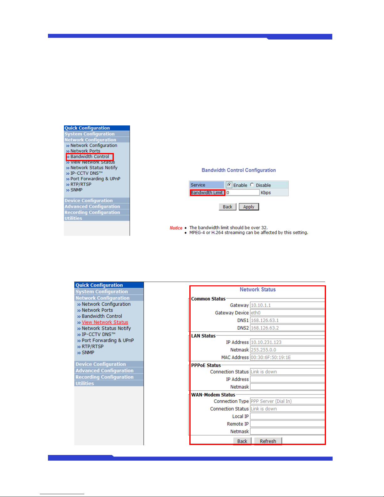
Bandwidth control is for limiting maximum network traffic. If it is enabled with certain limit, maximum data
size transferred from FlexWATCH products won’t exceed bandwidth limit set by users. If transferred data is
exceeded, part of data will be randomly lost
If multiple users try to access a FW product which bandwidth control is enabled, users connected to the
FW product will share network bandwidth limit.
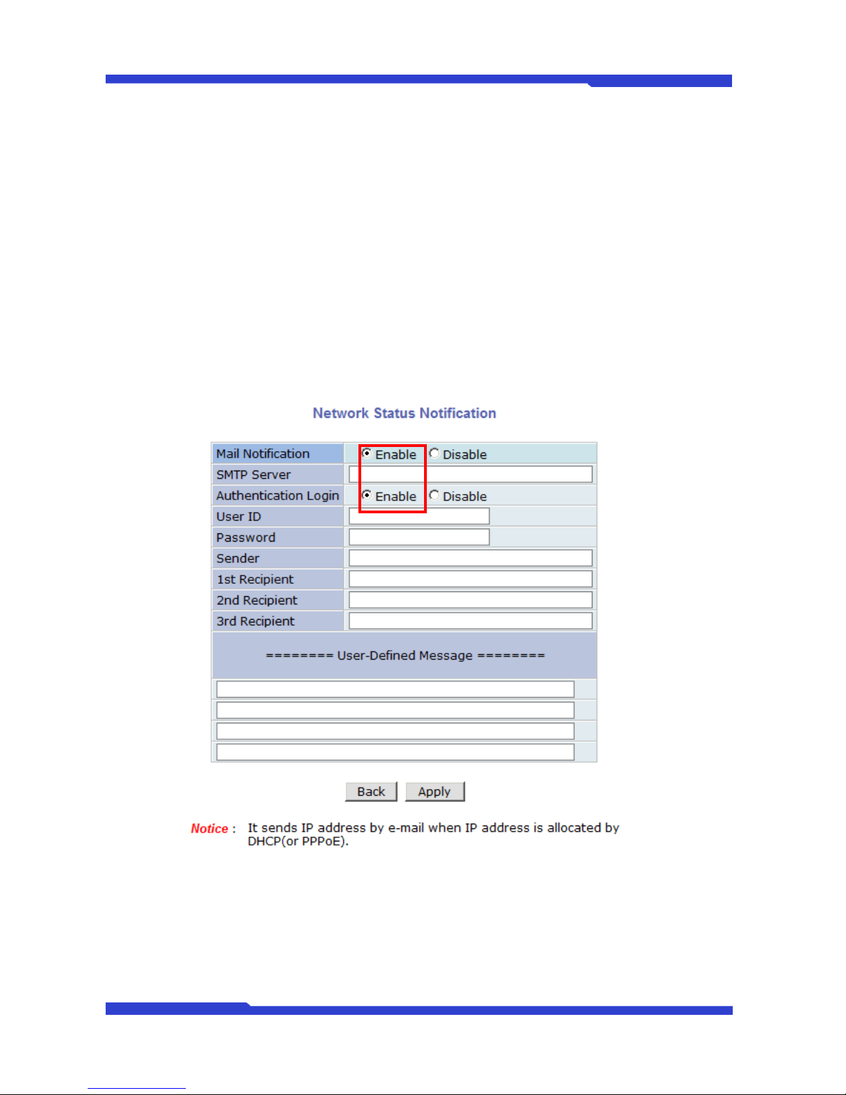
7.4. View Network Status
This menu shows network status of FW products. Wireless LAN status will be added for wireless models.
Page 25
FW3471 User’s Manual
M4068-00 25 Seyeon Tech Co., Ltd
7.5. Network Status Notify
This feature helps to send updated network status information to registered email address if any
changes happen. This function will work under DHCP or PPPoE.
If Network Status Notify is set to Enable, FlexWATCH™ Server’s network status will be emailed to a
specific person in case of the following events:
When it is set to Dynamic IP on Network Configuration menu, and the FlexWATCH™ server has been given
a new dynamic IP address and connected to the network.
Or,
When it is set to PPP Client on WAN-Modem menu, and the FlexWATCH™ server has been connected to
the network with ISP or PPP server.
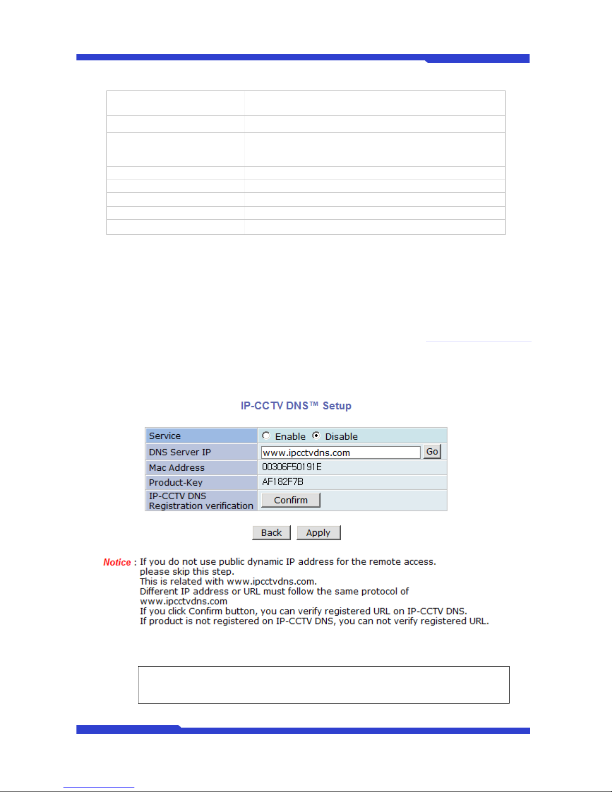
To configure, click “Network Status Notify” on Network Configuration menu. The following window will
be shown.
First, select Enable to use the feature. Then enter the address of the SMTP server which is needed for
email service. If your SMTP server requires a user ID and a password for authentication, you will have to get
them from ISP or network admin. Enter the ID and password.
In Sender field, enter your email address or other meaningful words that will show the message was
sent from the FlexWATCH™ server as a notification. Now enter the email addresses of the recipients in the
Recipient fields, up to 3 persons. In the User-Defined Message box, you may put a message to explain why
Page 26
FW3471 User’s Manual
M4068-00 26 Seyeon Tech Co., Ltd
the message was sent. After finishing the setup, click “Apply” to save settings.
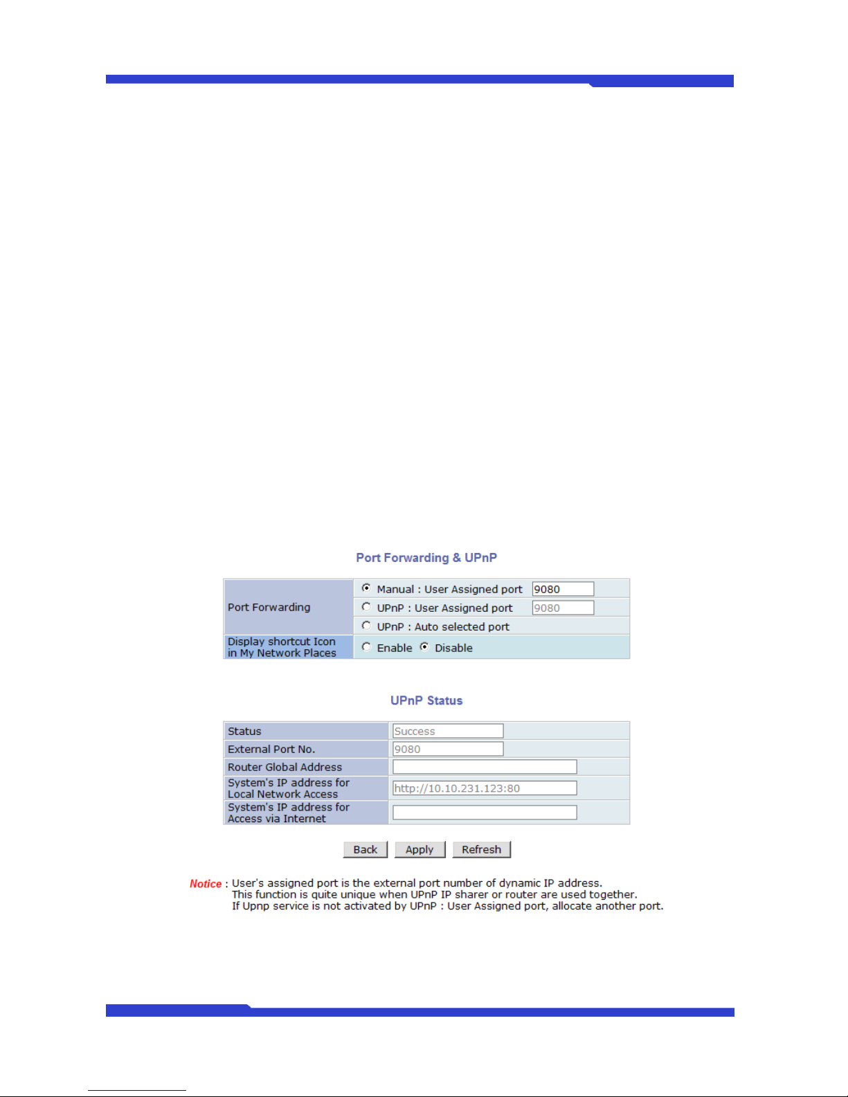
7.6. IP-CCTV DNS™ Setup
IP- CCTV DNS service provides a static & public domain name to help users access FlexWATCH
products even though their IP address is changed or they are used in local network. For proper function of IPCCTV DNS service, products should be accessible through internet.
To use IP-CCTV DNS, users have to create ID from IP-CCTV DNS server(http://www.ipcctvdns.com)
and register FlexWATCH products with MAC address and Product Key. Those information can be found from
IP-CCTV DNS Setup menu. Enable service and click Apply. If it is configured properly, you can check the
result by clicking Confirm button.
Mail Notification
Enable: Send email
Disable: Do not send email
SMTP Server
SMTP Server address for email service
Authentication Login
Enable: user ID and password are required for SMTP
server
Disable: user ID and password are not required
User ID
User ID for SMTP server
Password
Password for SMTP server
Sender
Email address of Sender
1st / 2nd / 3rd Recipient
Email Addresses of the Recipients (up to 3 persons)
User Defined Message
Message to be included in the Notification email
Note: Refer to IP-CCTV DNS™ User’s Manual for further details of the configuration.
Page 27
FW3471 User’s Manual
M4068-00 27 Seyeon Tech Co., Ltd
7.7. Port Forwarding & UPnP
UPnP(Universal Plug and Play) is a kind of network protocol to help users to find and configure network
products in same local network area. Port forwarding is to assign a certain network port to a network product
Proper so as users can access it from outside of Local Area Network. Generally, port forwarding can be
configured from network router.
UPnP port forwarding is made up with finding available network port, assigning it to a FlexWATCH
product and reporting overall network configuration of a FlexWATCH product to IP-CCTV DNS server. Users
have to register products to IPCCTVDNS server and IP-CCTV DNS service should be enabled.
There are 3 options in UPNP Port Forwarding.
Manual: User Assigned Port is used when users can access network router(hub) and manually
assign available network port to FlexWATCH products. In this case, users have to type alreadyassigned network port under User Assigned port
UPnP: User Assigned Port is used when users want FlexWATCH products to configure port
forwarding menu of network hub with user-assigned network port. If it fails, try to change userassigned port
UPnP: Auto Selected Port is used to let FlexWATCH products deal with all network configuration
automatically..
Please notice that network router should support UPnP Port Forwarding and there is a limit for maximum
UPnP devices. If it is properly configured, results will be appeared under UPnP status.
Page 28
FW3471 User’s Manual
M4068-00 28 Seyeon Tech Co., Ltd
7.8. RTP/RTSP
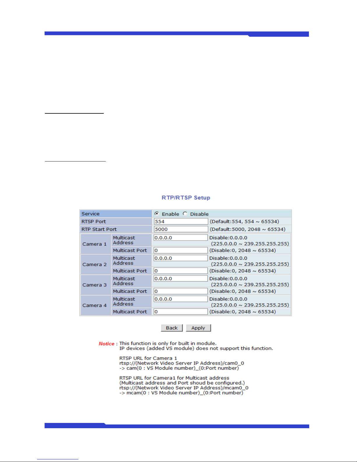
RTSP (Real-Time Streaming Protocol) is a protocol to transfer video and audio stream over the network.
Any application supporting Standard RTSP can be used for FlexWATCH server. Quick Time Player or VLC
program can be used for this, but it may not be supported in the environment within firewall. There are two
types of usages, one for Unicast address condition and the other for Multicast address condition.
For Unicast Address:
Use “rtsp://network video server ip address/cam0_0”. If there are multiple channels, use cam0_x, x
(0~3) with each number applied. If there are multiple modules, use camx_0 x (0 ~ 3) with each module number
applied.
For Multicast Address:
Use “rtsp://network video server ip address/mcam0_0”. If there are multiple channels, use mcam0_x,
x (0~3) with each channel number applied. If there are multiple modules, use mcamx_0 x (0 ~ 3) with each
module number applied.
Page 29
FW3471 User’s Manual
M4068-00 29 Seyeon Tech Co., Ltd
Service
Enable: Start RTSP service
Disable: Stop RTSP service
RTSP Port
In normal case, use default port number 554 to connect to RTSP service.
If not using port 554, enter the port number you want to use.
e.g.) port number 445==> rtsp:// network video server ip
address:445/cam0_0
RTP Start Port
The starting number of the port for video transfer. Each time video
transfer connection is made, the port number also increases.
Multicast
Address
Address for multicast video transfer.
The multicast address 0.0.0.0 is for stopping multicast.
Multicast Port
Port number for viewing the video with a multicast address
To use ONVIF protocol, RTP/RTSP must be enabled.
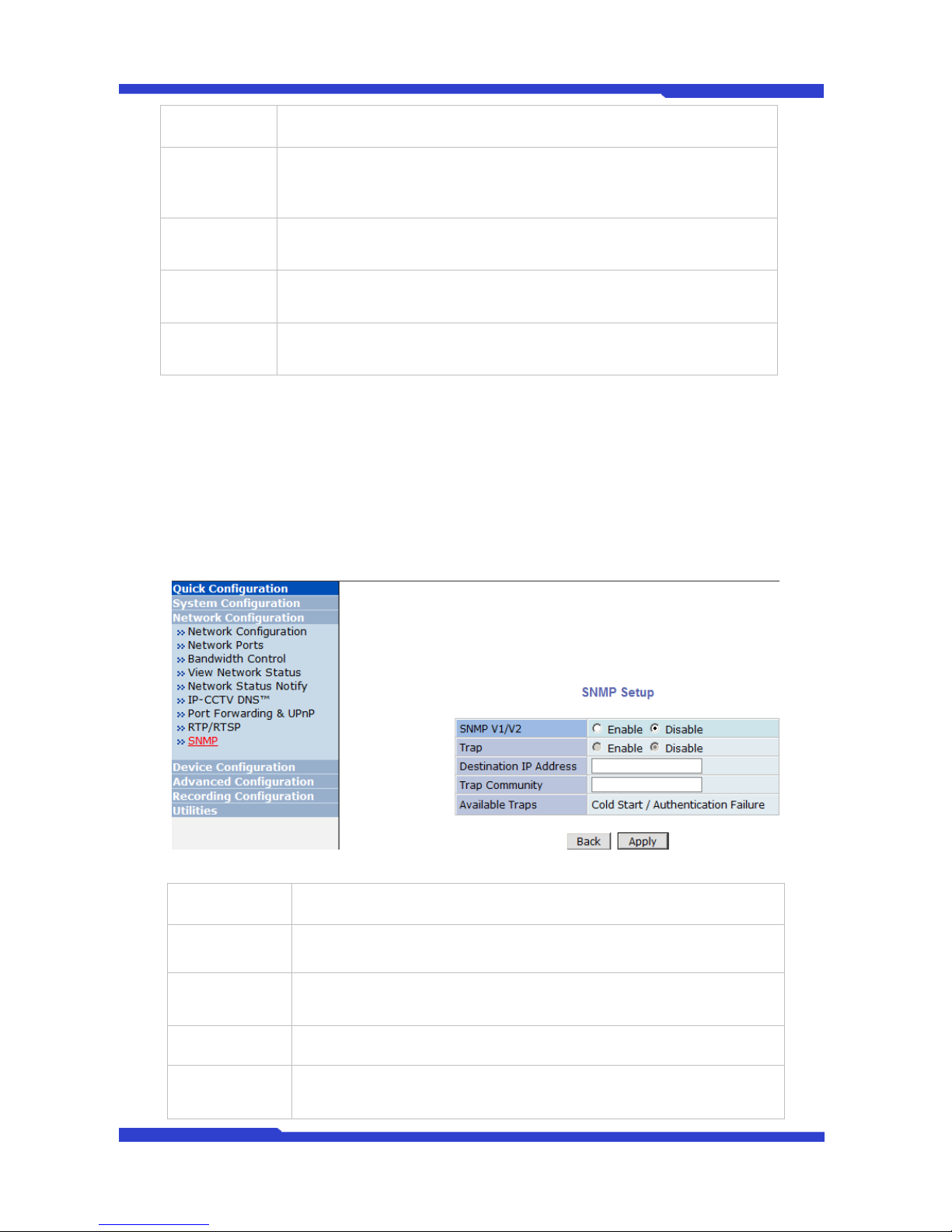
7.9. SNMP Setup
SNMP (Simple Network Management Protocol) is a protocol to monitor and configure network status of
a network device. SNMP V1 and V2 are supported over MIB2 standard, and few functions are not supported.
SNMP Trap can function when SNMP V1/V2 is enabled.
SNMP V1/V2
Enable: Start SNMP service
Disable: Stop SNMP service
Trap
Enable: Start SNMP Trap service
Disable: Stop SNMP Trap service
Destination IP
Address
IP Address to receive SNMP Trap messages.
Trap Community
Key value used in SNMP Trap e.g.) public
Available Traps
Type of SNMP Trap message
1. Cold Start : When SNMP starts
2. Authentication Failure : When key value of SNMP query is wrong
Page 30
FW3471 User’s Manual
M4068-00 30 Seyeon Tech Co., Ltd
8. Device Configuration
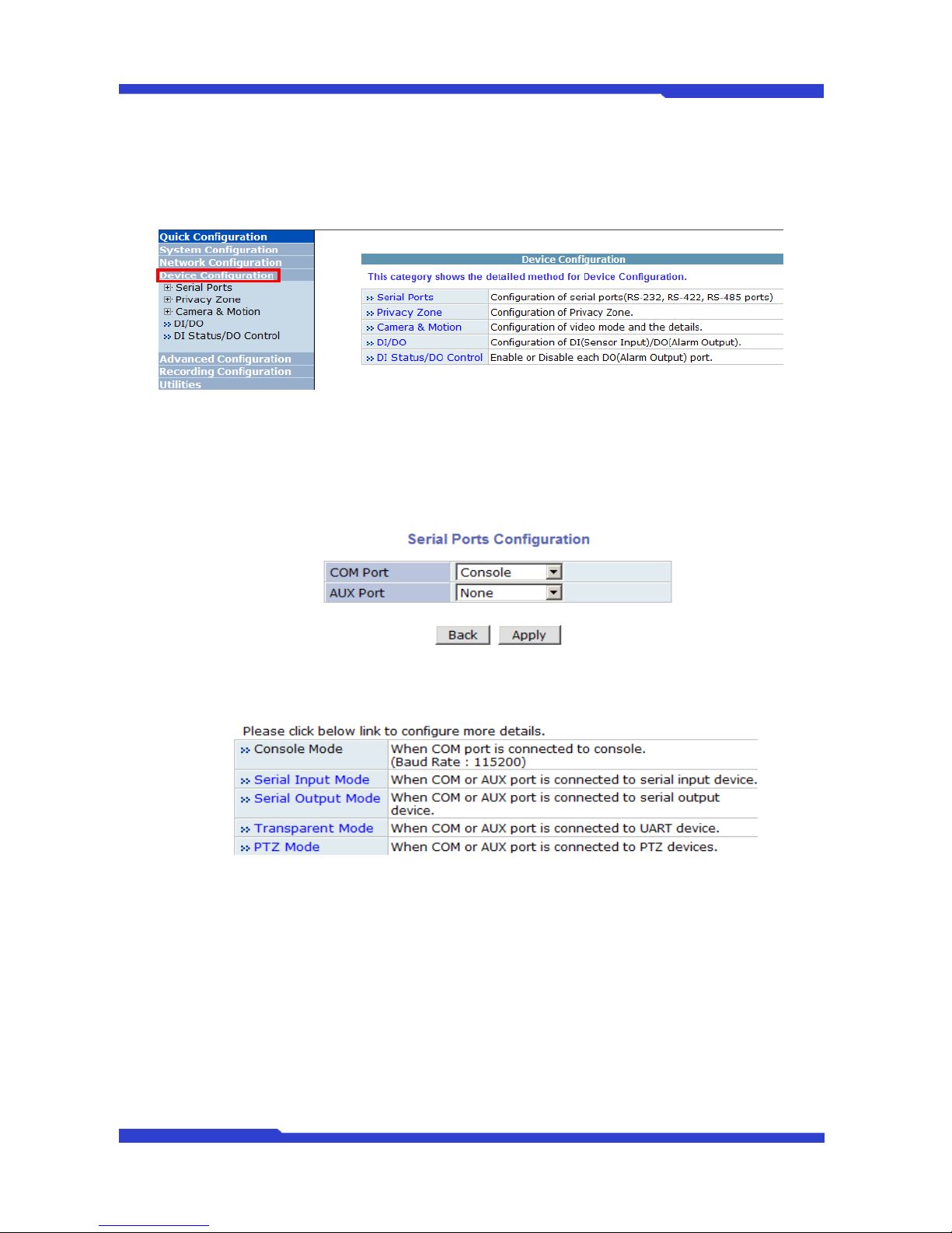
You set up the connection between FlexWATCH™ Server and the camera in this part of configuration.
That includes Video data, external devices, Input / Output, Alarm control, and etc.
8.1. Serial Ports Configuration
There are two serial ports configurable in the system, COM and AUX. COM port is primarily used for
console, and AUX is for PTZ control, but they both can be used for other purposes when necessary.
8.1.1. Serial Input Mode
When serial ports are in Serial Input Mode, FlexWATCH Server can be triggered by the external
sensors to send images from the camera by email, or FTP. It can also activate Alarm Output by input from
sensors inputs. For example in a real life, if a dam’s water level comes to a pre-defined value, the server can
send the images of the dam’s water level meter from cameras. Another example is, when a car running on
highway exceed the speed limit, it can send the picture of the car.
To configure, click Serial Ports on Device Configuration. In COM Port or AUX Port, select Serial Input
and click Apply button to apply the change. The system will reboot then.
Page 31
FW3471 User’s Manual
M4068-00 31 Seyeon Tech Co., Ltd
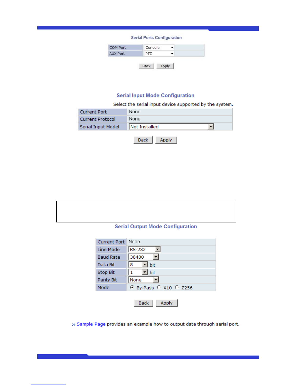
After rebooting, open the Serial Ports window in Device Configuration menu again. Select the Serial
Input Mode, then the Serial Input Mode Configuration windows will be displayed as shown below.
Current Port: This shows the name of the port currently configured.
Current Protocol: This shows the protocol being used. (only RS-232 can be displayed)
Serial Input Model: You can select the sensor’s model number to use for Serial Input.
8.1.2. Serial Output Mode
Note: If additional sensors need to be added, it will require installation of the device
drivers.
Page 32
FW3471 User’s Manual
M4068-00 32 Seyeon Tech Co., Ltd
8.1.3. Transparent Mode
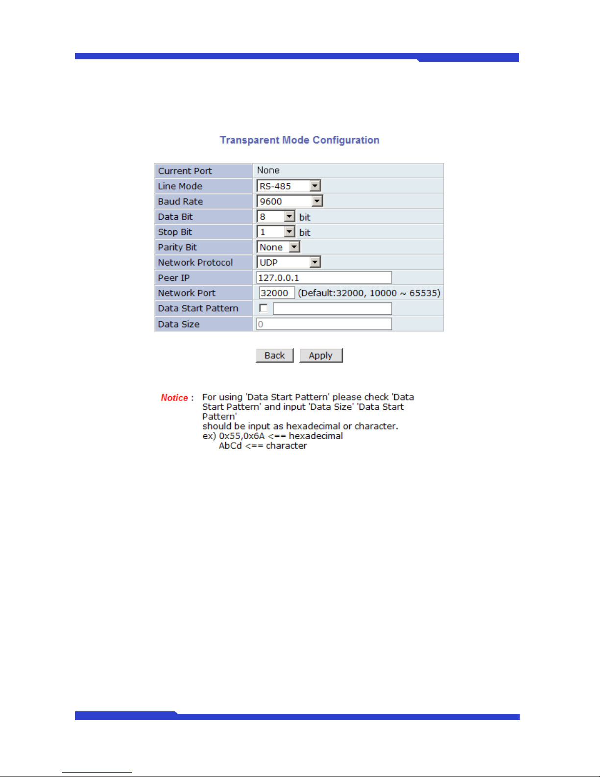
When there are two FlexWATCH™ Servers present on the network, they can act like a transparent
interface between two different UART devices so that the communication between the UART devices can be
made transparently without a flaw.
Line Mode: The type of communication protocol
Baud Rate: Data transfer rate
Data Bit: The number of bits in data
Stop Bit: The number of stop bit
Parity Bit: Parity bit characteristic
Network Protocol: The type of protocol used to send data
Peer IP: IP address of other FlexWATCH™ server
Network Port: Network port number of the server
Data Start Pattern: Data start pattern (Not used if unchecked)
Data Size: Data size in single transfer (Not used if unchecked)
9. Advanced Configuration
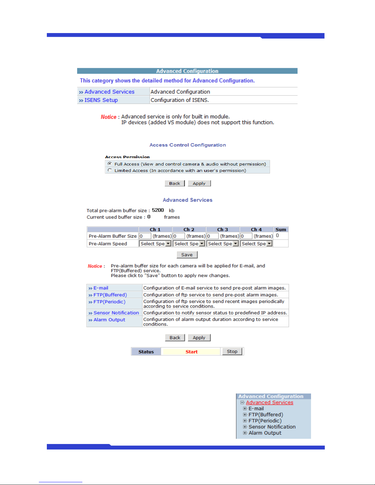
FlexWATCH can be configured to start and stop certain pre-defined services by scheduling, event, or
conditions. It also has ISENS feature, which is a way of integrating FlexWATCH with CMS software.
You can set up the advanced services in Advanced Configuration menu.
There are two types of advanced service, one is Buffered Service and the other is Periodic Service. In
Page 33
FW3471 User’s Manual
M4068-00 33 Seyeon Tech Co., Ltd
Buffering Service, a series of images are continuously being stored in a buffer memory of server for a certain
period of time. When the server is triggered by an event or schedule, the images or alarm status just before
and after the event/schedule are reported to you by email or buffered FTP services.
9.1. Advanced Services
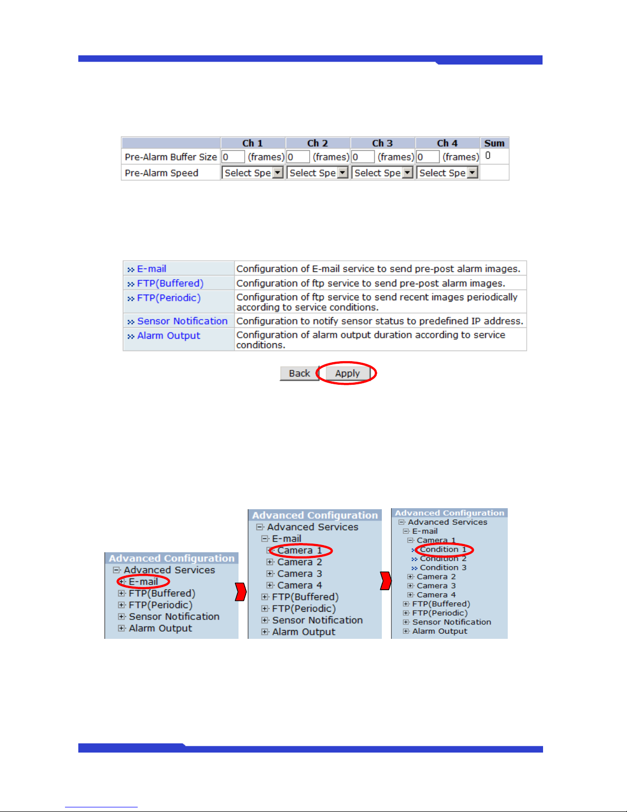
Total Pre-Alarm buffer size and buffering speed can be defined here.
Page 34
FW3471 User’s Manual
M4068-00 34 Seyeon Tech Co., Ltd
Pre-Alarm Buffer Size: You can set the buffer size which will store the images before event. The unit
is in frame, and each channel can be set with different values. The total number of frames for PreAlarm Buffer and Post-Alarm Buffer is limited to 10 frames.
Pre-Alarm Speed: You can set the buffering speed. If it’s set to Fastest, the server will store images
as fast as it can. Each cannel can be set with different values.
This configuration applies to E-mail and FTP (Buffered), and click Save button to apply changes.
E-mail: Set up Email Service configuration
FTP (Buffered): Set up FTP (Buffered) Service configuration
FTP (Periodic): Set up FTP (Periodic) Service configuration
Sensor Notification: Set up configuration such as CGI by notification
Alarm Output: Set up Alarm Output (DO Control) configuration
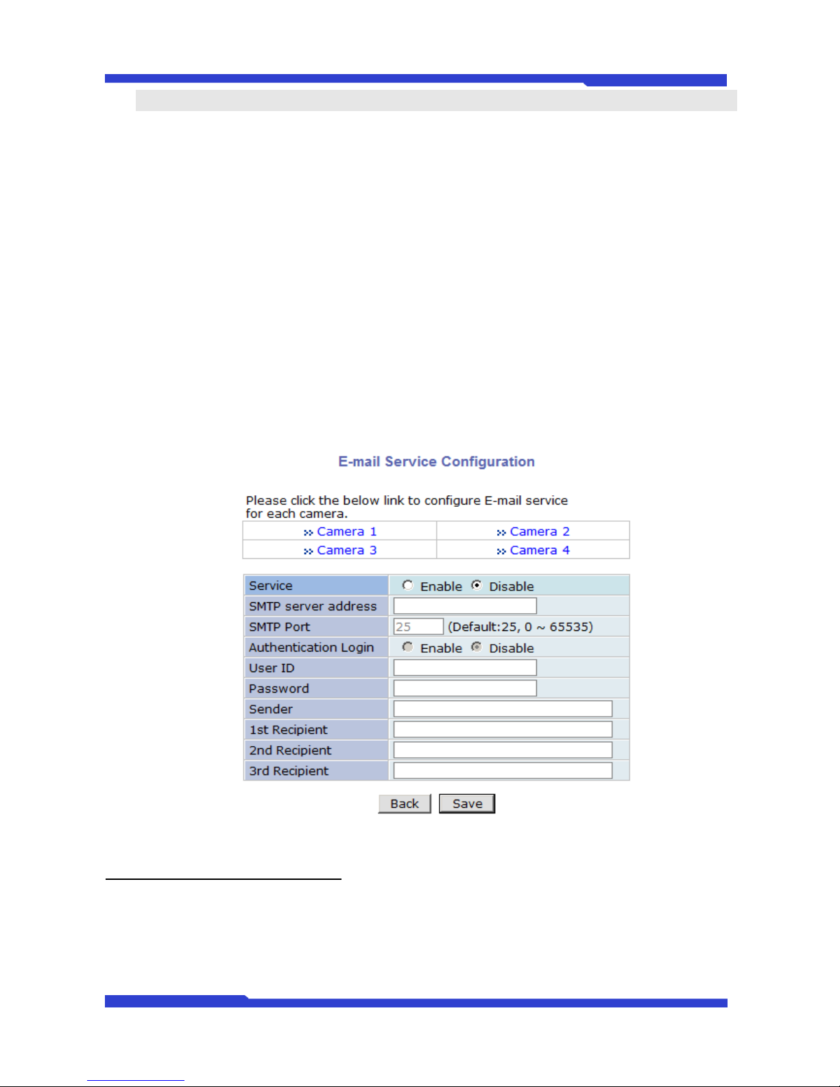
9.1.1. E-mail Service Configuration
Email configuration is set up here for Alarm in case any event occurs.
Page 35
FW3471 User’s Manual
M4068-00 35 Seyeon Tech Co., Ltd
Click Save button to apply the change. If you don’t want to change, click Back button.
E-mail Service Setup for Each Channel
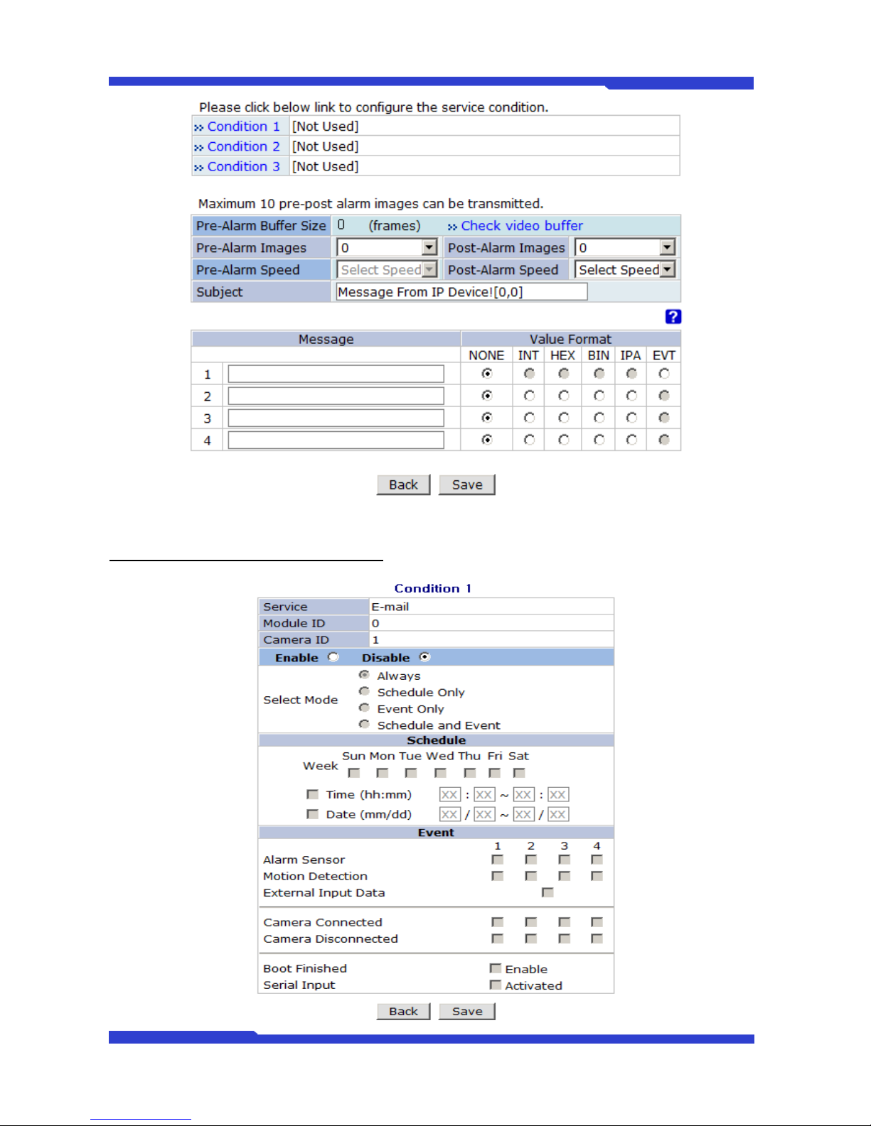
For each channel, the following items can be configured for email service: Condition, Post-Alarm, Buffer Size,
and Post-Alarm speed. The content of text message and display style of DI value can be configured as well.
Item
Description
Condition 1 ~ Condition
3
Select a condition for Email service to be activated.
Pre-Alarm Buffer Size
The Buffer size assigned for Pre-Alarm.
Check Video buffer
Click this link to go to Advanced Services for buffer setup.
Pre-Alarm Images
The number of image frames to store before Alarm
Post-Alarm Images
The number of image frames to store after Alarm
Pre-Alarm Speed
This field shows the speed of Pre-Alarm. Configuration can be done in
Advances Services page.
Post-Alarm Speed
Select the speed of Post-Alarm. Fastest is the highest value.
Subject
Subject of the E-mail message to send.
1
Content of the first line in the email message.
2
Content of the second line in the email message.
3
Content of the third line in the email message.
4
Content of the fourth line in the email message
Value Format
Select the format for the Event or DI data to email.
NONE: Don’t Send, INT: Decimal, HEX: Hexadecimal,
BIN: Binary, IPA: IP Address, EVT: Name of Event
Page 36
FW3471 User’s Manual
M4068-00 36 Seyeon Tech Co., Ltd
After finishing setup, click Save button to apply. If you don’t want to change, click Back button.
Condition, Schedule & Event Configuration
Page 37
FW3471 User’s Manual
M4068-00 37 Seyeon Tech Co., Ltd
If you click on a Condition link, the Advanced Service windows is displayed as shown below.
Alarm Service is activated only when the conditions in Advanced Services are met.
Item
Description
Service
This shows what service this condition is for.
Module ID
Module ID for current setup
Camera ID
Channel ID for current setup
Enable / Disable
Select Enable to use Condition, otherwise select Disable.
Always
This Condition applies all the time. (Schedule or Event is not usable)
Schedule Only
Use Week, Time, and Date in Condition parameter. If none of weekdays is
set, it is activated every day.
Event Only
It is activated only when any of the following events occurs.
(Sensor, Motion Detection, Camera Connection, Server Booting)
To save the setting, click Save button. If you want to cancel it, click Back.
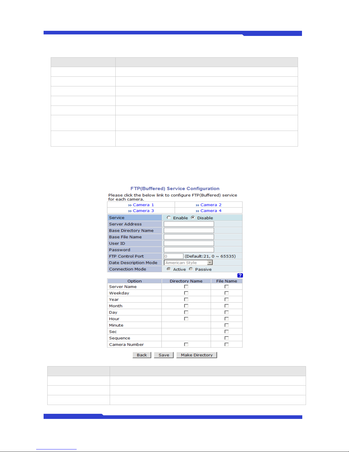
9.1.2. FTP(Buffered)Service Configuration
Item
Description
Camera 1 - Camera 4
Select which channel to set up for FTP (Buffered).
Service
Select Enable to use the FTP (Buffered) service. Otherwise select Disable.
Server Address
FTP Server Address.
Page 38
FW3471 User’s Manual
M4068-00 38 Seyeon Tech Co., Ltd
Base Directory Name
The directory in FTP server where the data will be uploaded.
(You should make the directory in the FTP server before using the service.)
Base File Name
The base file name of the data to be uploaded in FTP server.
User ID
Enter a User ID to log in to FTP server.
Password
Enter the Password for the user ID to log in to FTP server
FTP Control Port
Port number for FTP server (Normally 21 is used)
Date Description Mode
Select Date Display Style (e.g. 20090228)
Connection Mode
Select connection mode for FTP server
Server Name
If Directory Name is checked, new directory is created with server name.
If File Name is checked, new file is created with server name.
Weekday
If Directory Name is checked, new directory name is created with weekday.
If File Name is checked, new file name is created with weekday.
Month
If Directory Name is checked, new directory name is created with month.
If File Name is checked, new file name is created with month.
Day
If Directory Name is checked, new directory name is created with day.
If File Name is checked, new file name is created with day.
Hour
If Directory Name is checked, new directory name is created with hour.
If File Name is checked, new file name is created with hour.
Minute
If checked, new file name is created with minute.
Sec
If checked, new file name is created with second.
Sequence
If checked, new files are created starting from 0, with increment of 1.
Camera Number
If Directory Name is checked, new directory is created with camera number.
If File Name is checked, new file is created with camera number.
To create a directory with the options shown above, click Make Directory button. After finishing the
configuration, click Save button to apply the change and continue to the next page. Clicking Back button will
cancel the changes and go back to the previous page. (This service is available only in M-JPEG mode.)
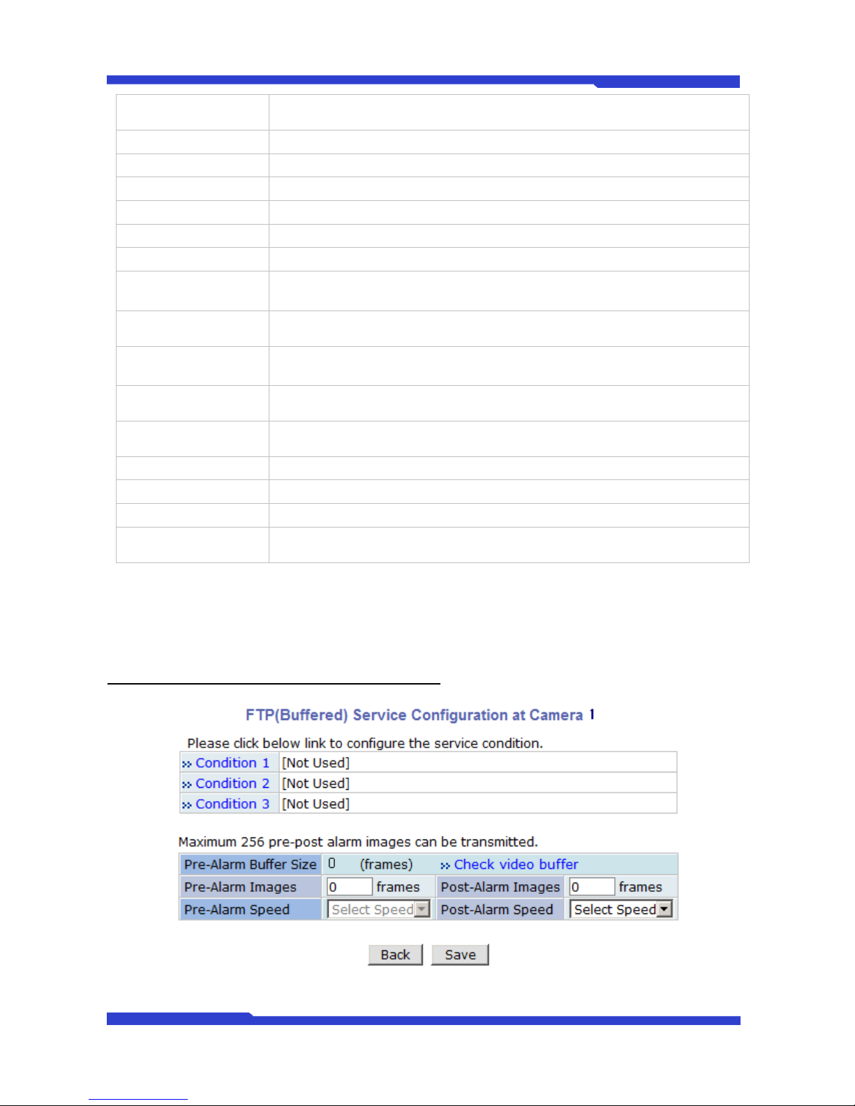
FTP(Buffered) Service Configuration for each Camera
Page 39
FW3471 User’s Manual
M4068-00 39 Seyeon Tech Co., Ltd
Item
Description
Condition 1 ~ Condition
3
Select a condition for FTP (Buffered) service to be activated. Up to 3
conditions can be set.
Pre-Alarm Buffer Size
The Buffer size assigned for Pre-Alarm.
Check Video buffer
Click this link to go to Advanced Services for video buffer setup.
Pre-Alarm Images
The number of image frames to store before Alarm.
Post-Alarm Images
The number of image frames to store after Alarm.
Pre-Alarm Speed
This field shows the speed of Pre-Alarm. Configuration can be done in
Advances Services page.
Post-Alarm Speed
Select the speed of Post-Alarm. Fastest is the highest value.
After finishing setup, click Save button to apply. If you don’t want to change, click Back button.
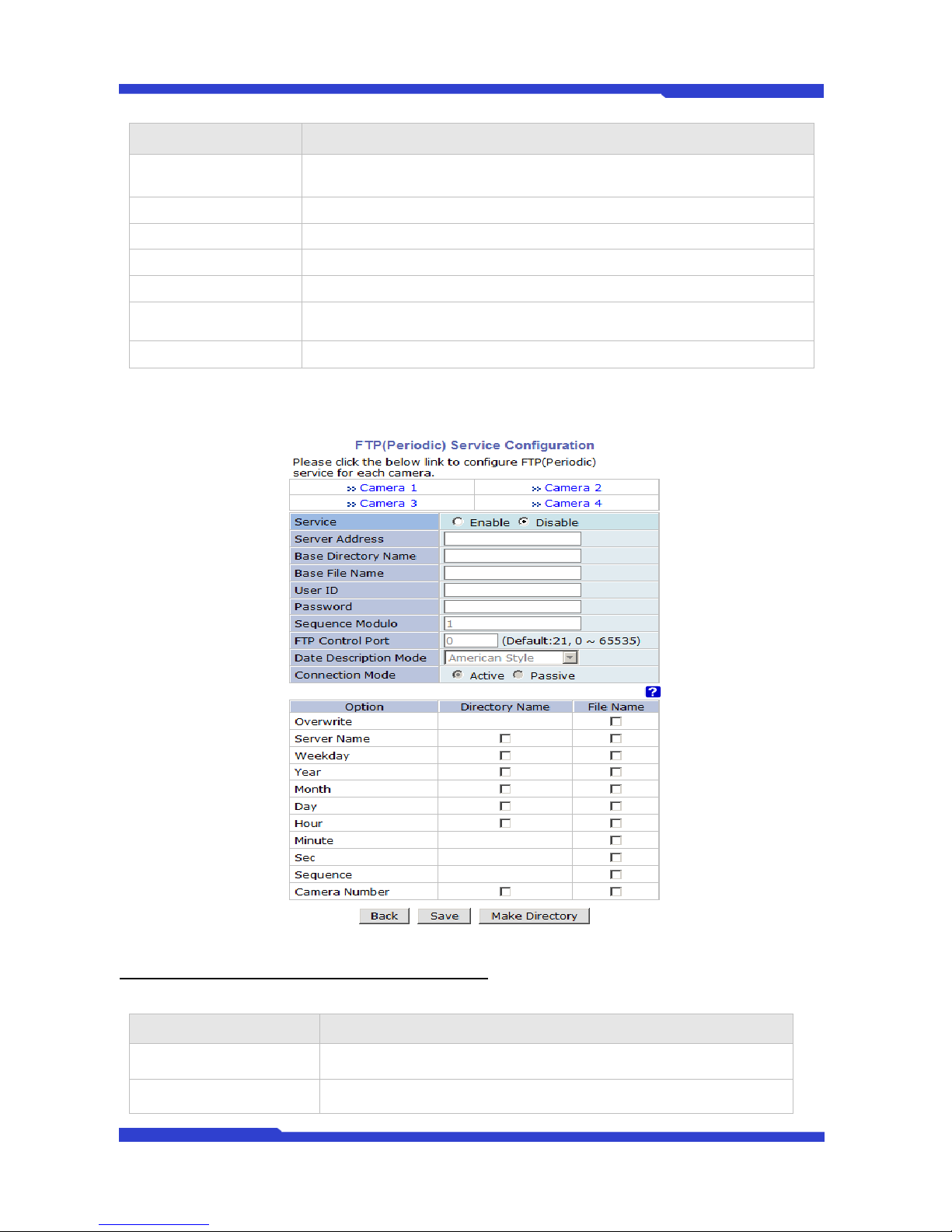
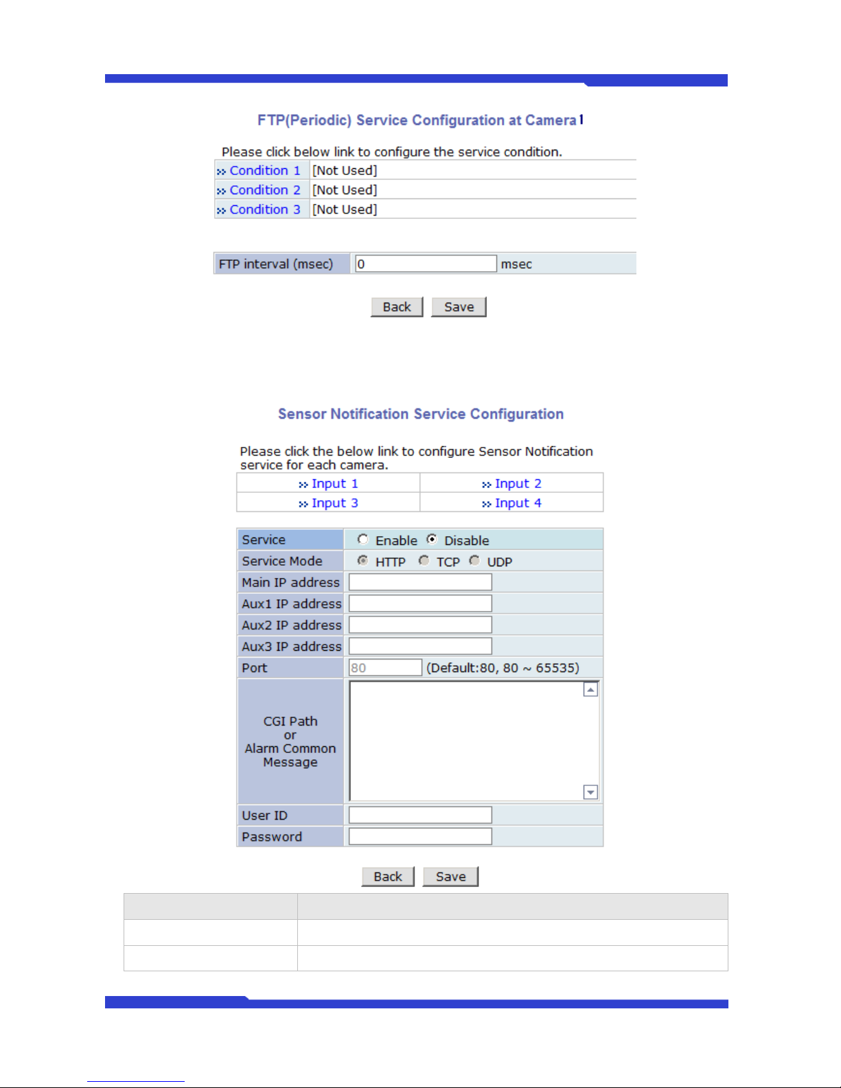
9.1.3. FTP(Periodic) Service Configuration
FTP(Periodic) Service Configuration for each Camera
Item
Description
Condition 1 ~ Condition 3
Select a condition for FTP (Periodic) service to be activated. Up to 3
conditions can be set respectively.
Alarm Speed
Select the speed of images to send in FTP(Periodic) service
Page 40
FW3471 User’s Manual
M4068-00 40 Seyeon Tech Co., Ltd
After finishing setup, click Save button to apply. If you don’t want to change, click Back button.
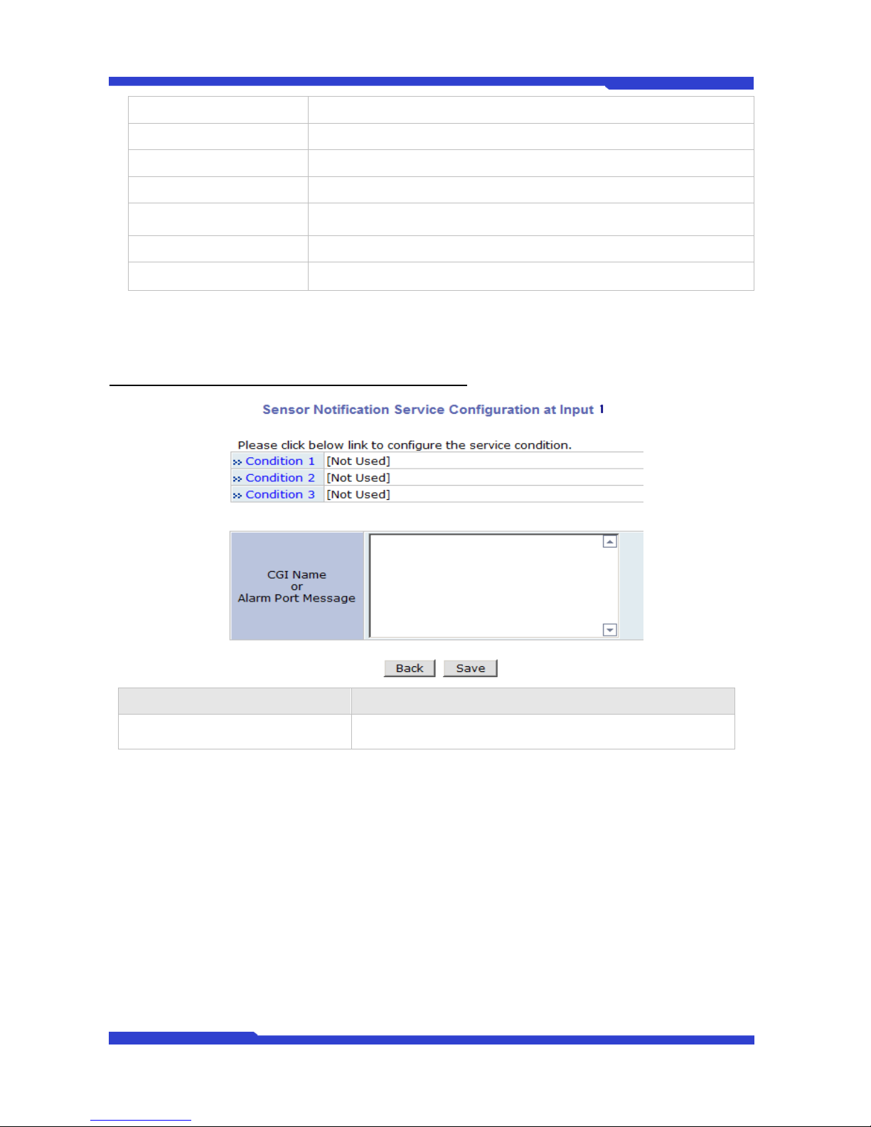
9.1.4. Sensor Notification
Item
Description
Input 1 - Input 4
Select which input to set up for Sensor Notification Service
Service
Select Enable to use Sensor Notification. Otherwise select Disable.
Page 41
FW3471 User’s Manual
M4068-00 41 Seyeon Tech Co., Ltd
Service Mode
Select network mode for CGI. Select one among HTTP, TCP, or UDP.
Main IP address
Enter IP address to use in CGI or other functions
Aux1 ~ Aux 3 IP address
Enter 3 more addresses to use in CGI or other functions if needed.
Port
Enter port number for CGI or other functions. Default is 80.
CGI Path or
Alarm Common Message
Enter CGI Path for CGI or other functions.
User ID
Enter User ID to log in.
Password
Enter Password for the User ID to log in.
After finishing the configuration, click Save button to apply the change and continue to the next page.
Clicking Back button will cancel the changes and go back to the previous page.
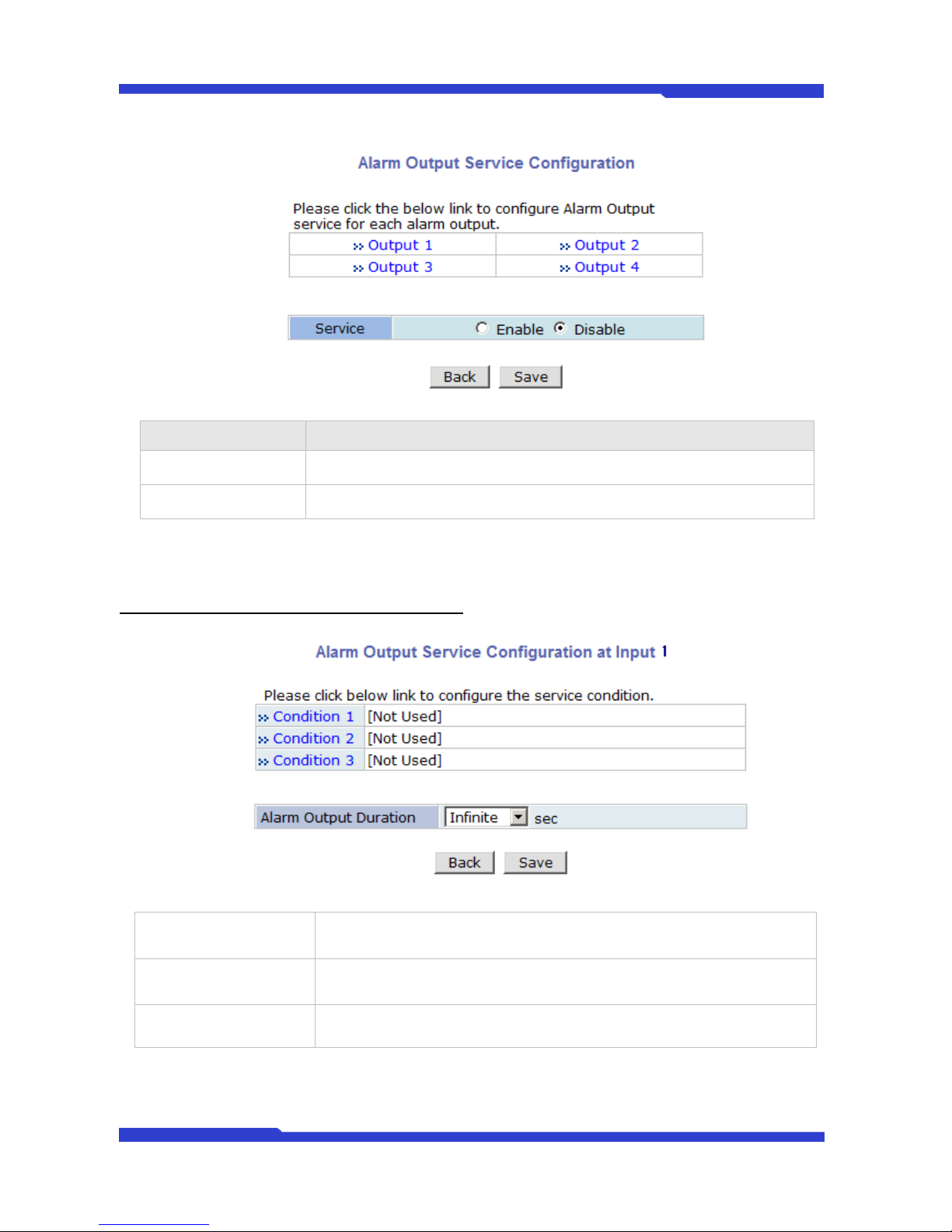
Sensor Notification Service Configuration for Each Input.
Item
Description
CGI Name or Alarm Port Message
Enter the contents of CGI when it is used.
Click Save button to save the change. Clicking Back button will cancel the change and go back to previous
page.
Page 42
FW3471 User’s Manual
M4068-00 42 Seyeon Tech Co., Ltd
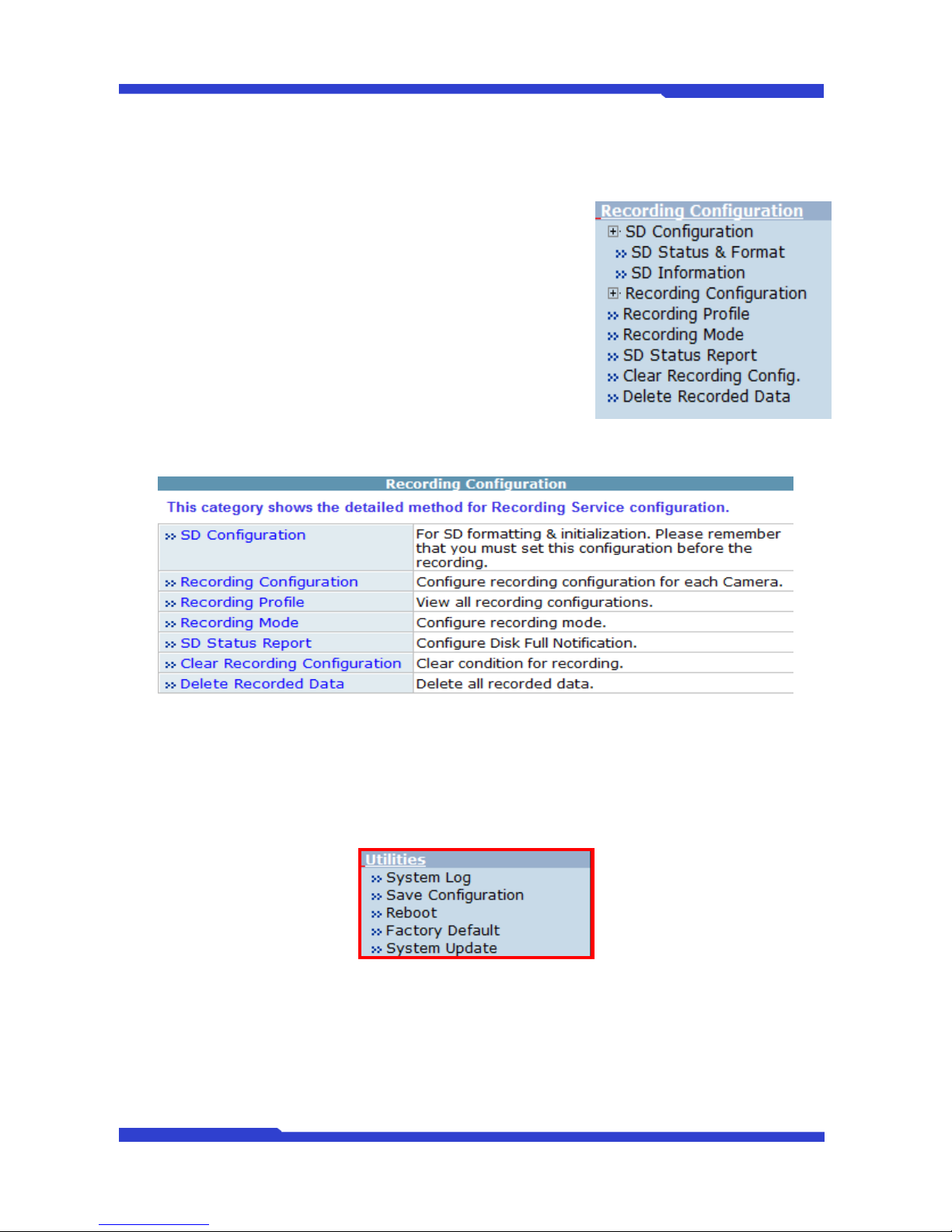
9.1.5. Alarm Output Service Configuration
Category
Contents
Output 1 – Output 4
Select the output port to configure for Alarm Output Service.
Service
Select Enable to use the service, otherwise select Disable.
After finishing the configuration, click Save button to apply the change and continue to the next page.
Clicking Back button will cancel the changes and go back to the previous page.
Alam Output Service Configuration for each Input
Category
Contents
Condition 1 - Condition 3
Select a condition to configure Alarm Output Service. Up to 3 conditions
can be set respectively.
Alarm Output Duration
Select how long the Alarm Output signal is maintained. Unit is in second.
Page 43
FW3471 User’s Manual
M4068-00 43 Seyeon Tech Co., Ltd
10. Recording Configuration
11. Utilities
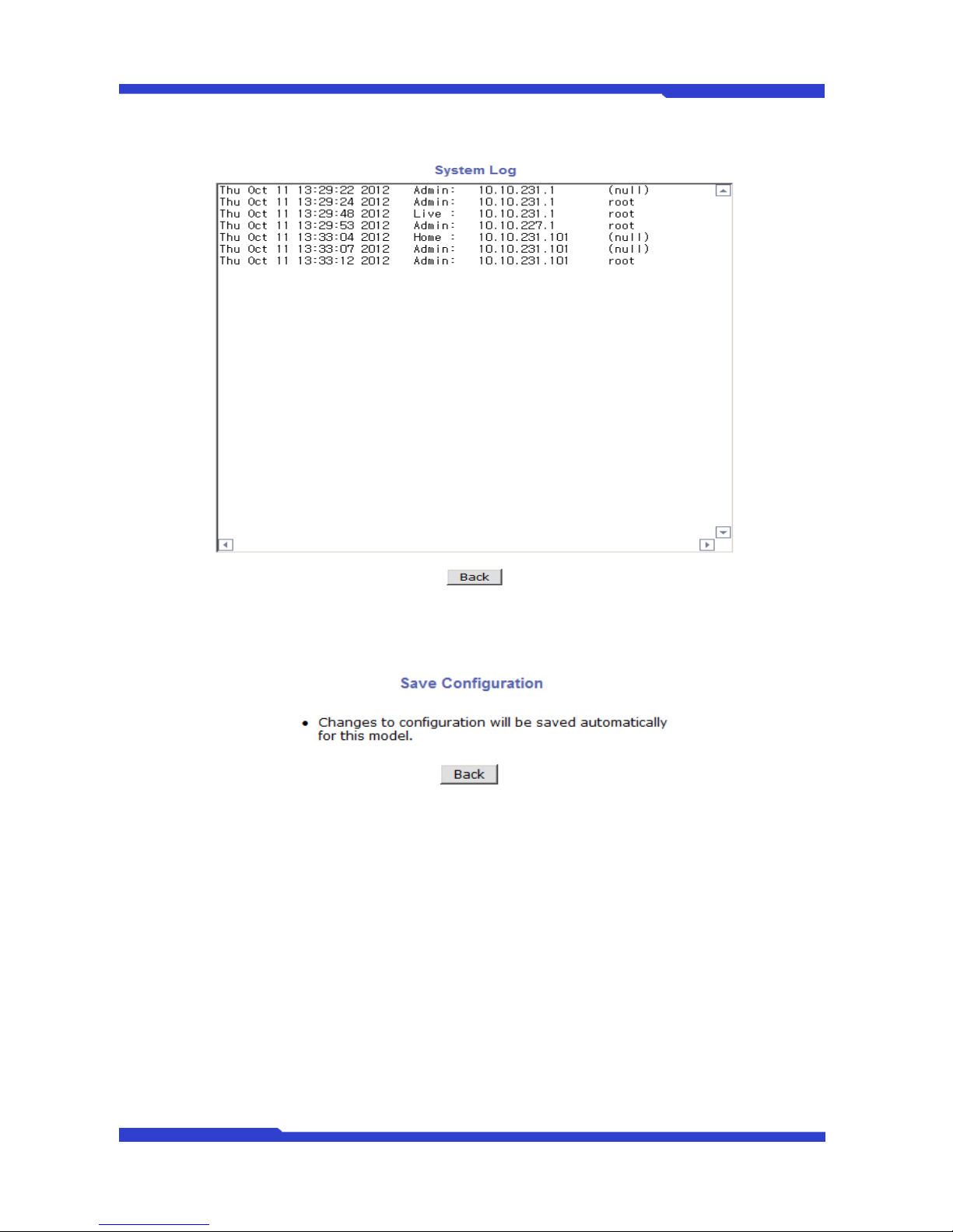
In Utilities part of the Admin menu, you can view the system log file, save the changed value during the
configuration, reboot, restore the factory default condition, and update the system.
It is possible to record and search the video data sent from camera if
the FlexWATCH Server is equipped with a hard disk drive. Recording
configuration is available only when a hard drive is up and running in
the server. You can format the hard drive, check the information of the
drive, and set the recording conditions of motion detection and event.
Some versions of FlexWATCH network cameras (FW1170VO/FW1173-DS/FW1173-MS/FW1173-FS/FW1174-VC/FW1174MC/FW1175-DS/FW1175-MS/FW1175-FS/FW1176-DS/FW1176MS/FW1176-FS) have microSD slots on the back. Those models can
record video if microSD card is present in the slot, which supports 1GB
to 32GB.
Page 44
FW3471 User’s Manual
M4068-00 44 Seyeon Tech Co., Ltd
11.1. System Log
11.2. Save Configuration
11.3. Reboot
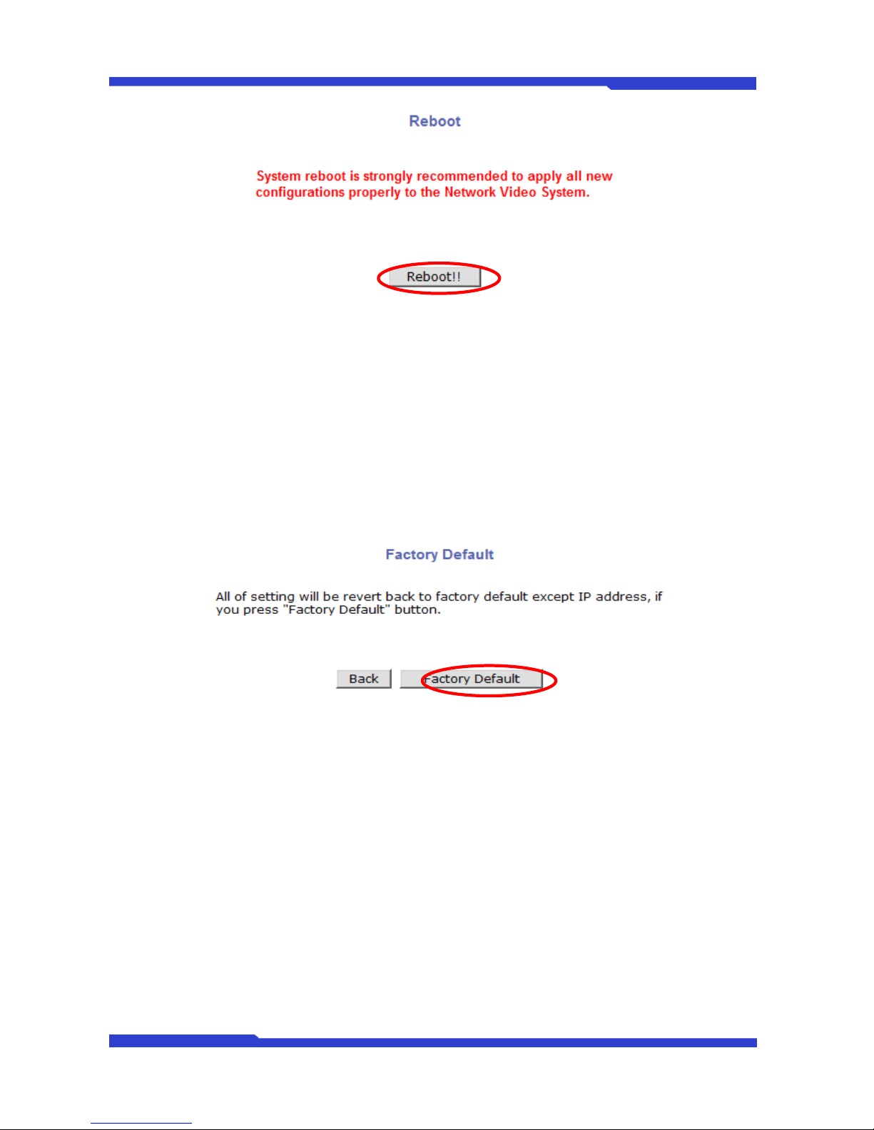
It is recommended to reboot the system after making changes and saving the configuration. To reboot,
click “Reboot" on Utilities menu. A confirmation screen will be displayed as shown Click “Save
Configuration” button, otherwise click “Back” button to cancel the rebooting.
The second confirmation screen will be shown. This is only to confirm closing of web browser that
FlexWATCH™ Server is on. Click “OK” button to close the web browser and reboot right away. If you click
“Cancel”, the web browser is still open, but you will not be able to access the FlexWATCH™ Server until the
rebooting is finished.
Page 45
FW3471 User’s Manual
M4068-00 45 Seyeon Tech Co., Ltd
11.4. Factory Default
Whenever it is required to restore the configuration of Camera setup to factory default condition, you can
do it here. Network configuration is not affected by this action.
Click “Factory Default” on Utilities menu. A confirmation screen will be displayed as shown Click
“Factory Default” button, otherwise click “Back” button to cancel it. The second confirmation screen will
appear. Click “OK” button to restore the factory default condition right away. If you click “Cancel”, web
browser will go back to the previous screen without any change made.
11.5. System Update
FlexWATCH™ Server’s system program and data are stored in Flash memory, and it consists of Kernel
Image, RAM Disk Image, System Image, and Web Image. In order to update the system of the server, you
should have proper image files ready in your PC.
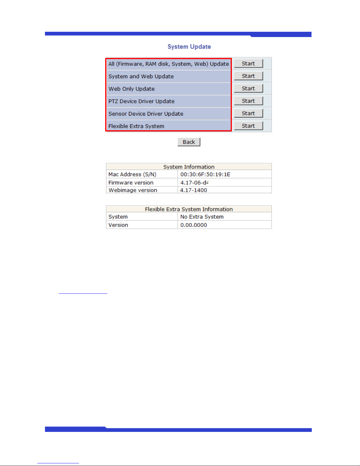
Click “System Update” on Utilities menu, then the following window will be displayed. From the Start
buttons displayed, choose the one that meets your needs.
Page 46
FW3471 User’s Manual
M4068-00 46 Seyeon Tech Co., Ltd
All (Firmware, RAM disk, System, Web) Update: Update all four system images.
System and Web Update: Only System and Web images are to be updated.
Web Only Update: Only Web image is to be updated.
Up-to-date system files can be downloaded in Support page of Seyeon Tech’s homepages at
http://www.flexwatch.com. After the update is done, it is required to reboot the server.
11.5.1. Update by Item
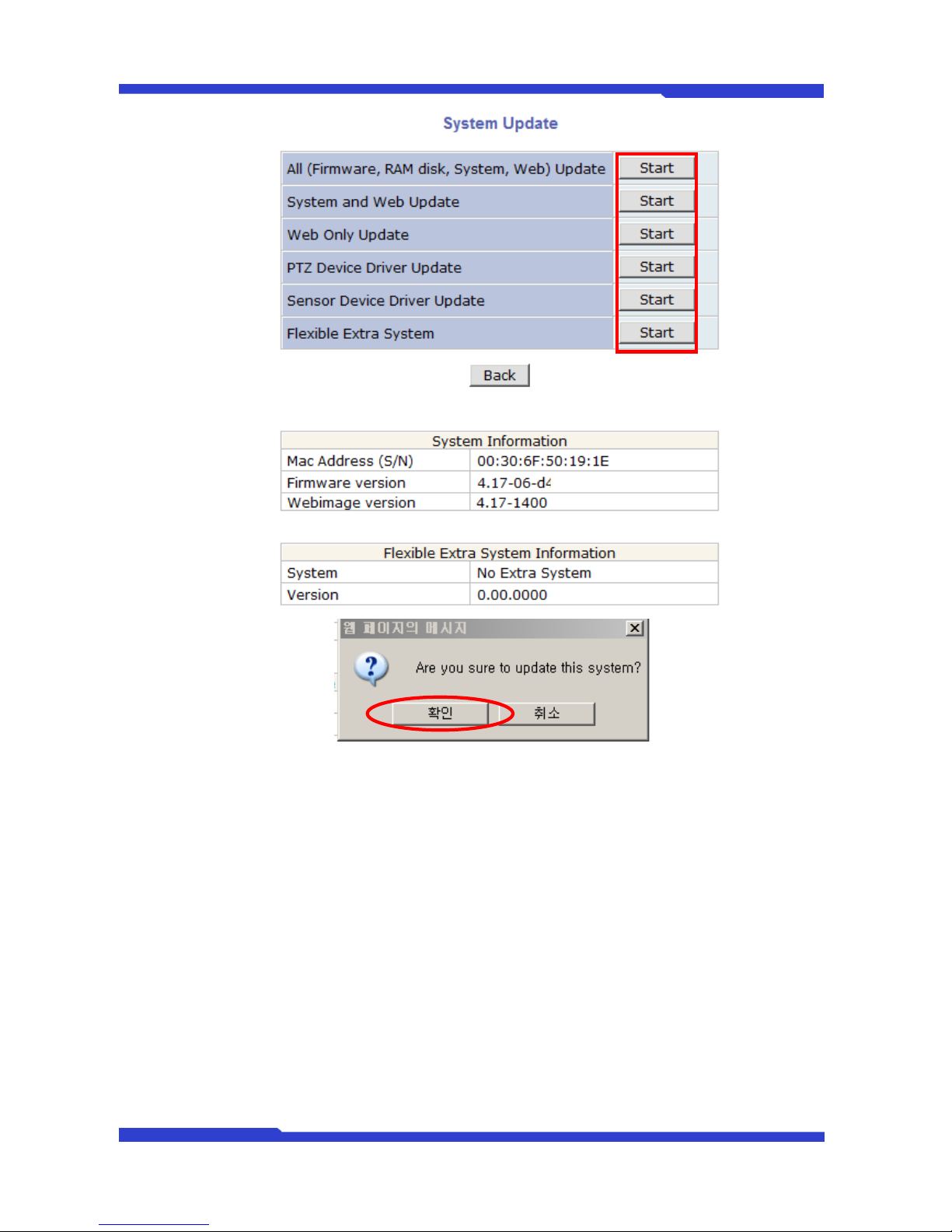
Click the “Start” button next to All (Firmware, RAM disk, System, Web) Update and the other
items on the menu, and a confirmation window will appear. Click “OK” button to proceed the update,
otherwise click “Cancel”.
Page 47
FW3471 User’s Manual
M4068-00 47 Seyeon Tech Co., Ltd
 Loading...