

Page 1
Made in U.S.A.
Earthworks, Inc. • 37 Wilton Rd. • Milford, NH 03055
603-654-2433, ext. 114 • www.earthworksaudio.com
email: [email protected] • Printed in U.S.A.
User’s Manual
FW730
FW730/HC
FW730-TPB
FW730/HC-TPB
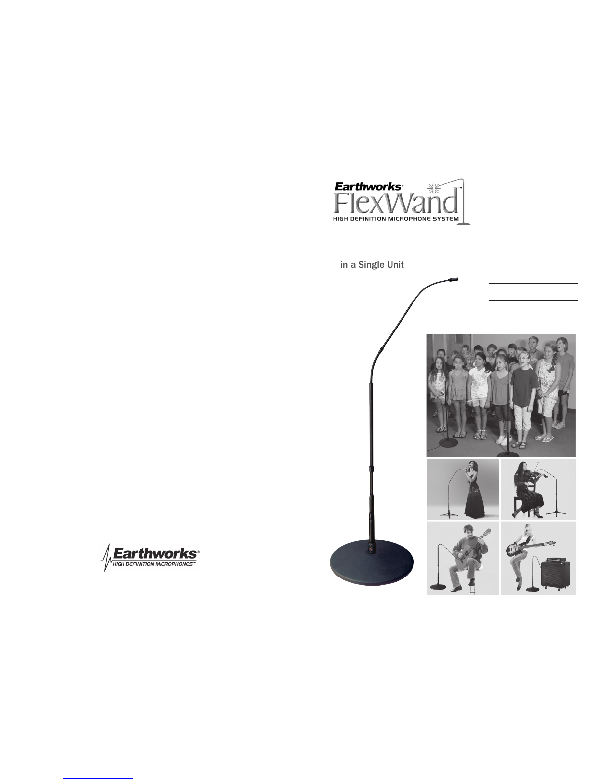
High Definition
Microphone System
A Microphone,
Boom and Stand
in a Single Unit
Page 2
inside front cover
When miking groups or ensembles the Earthworks near-perfect polar response allows
placing the microphones much closer to the instruments or voices resulting in greater
detail in the sound and more gain-before-feedback.
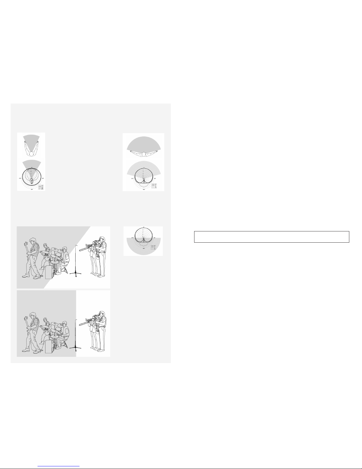
Earthworks cardioid microphones provide incredible rejection of sound from the rear
of the microphone. Notice in
Figure C that this dead area
of the microphone covers
180 degrees. Figure D shows
the way “not to” position the
microphone. Figure E shows
the “correct” way to position
the microphone and obtain
the greatest amount of rejection of sounds coming from
the rear of the microphone.
Following these guidelines
will provide incredible results.
You should be more than
pleased!
Figure A Usable area
with full frequency re-
sponse of conventional
cardioid microphones
BEFORE YOU START Guidelines for Positioning FW430 FlexWands
Earthworks near-perfect polar response may require some changes or adjustments in
your typical miking practices. Please read the manual to gain a full understanding of
the pick-up characteristics of Earthworks cardioid microphones.
Figure B Usable area with full
frequency response of Earth-
works cardioid microphones
Figure C Rear rejection area of
Earthworks cardioid microphones
There is a dramatic difference in
the pick-up area with full frequency
response (i.e. no signicant high
frequency loss) between a conventional cardioid microphone and an
Earthworks cardioid microphone with
near-perfect polar response. These
differences can be seen in comparing
Figures A and B. So, when using an
Earthworks cardioid microphone you
must think “wider” when you position
your microphones. The Earthworks
cardioid mics have a much greater
reach on the sides than conventional
cardioid microphones.
Figure E CORRECT
maximum isolation from
the band
Figure D INCORRECT poor
isolation from the band
Congratulations on your purchase of the innovative Earthworks High Deni-
tion Microphone™ FW430 FlexWand™ System. We know you will be thrilled
with the results you achieve using the FlexWand™ System for both live per-
formance and recording.
Enclosed with your Earthworks FW430 FlexWand™ System:
FlexWand™ Models FW430 & FW430/HC with cast iron base, or
FW430TPB & FW430/HC-TPB with tripod base
1 – FlexWand™ stand/wand section *
1 – Microphone windscreen *
1 – Base for stand/wand section (either cast iron metal or tri-
pod base depending on model) *
1 – User’s Manual for FlexWand™ System
* (If you purchased a matched pair of FlexWands, you will receive two each of the
items indicated above with an asterisk.)
THE FLEXWAND™ SYSTEM
You have just purchased an Earthworks High Denition Microphone™ that is incor-
porated in the FlexWand™ System. The FlexWand™ System is a totally new concept
in microphones. It is a combination of a High Denition Microphone™ and a low
prole microphone stand and boom as a single unit. It allows the microphone head
to be positioned as high as 4.7 feet and as low as 10 inches from the oor or any-
where in between using the tripod base. Using the cast iron base (which is 4 inches
lower) changes the maximum height to 4.45 feet and minimum height to 6 inches.
Best of all there are no visible wires or cables above oor level. Visually it is low prole, smooth, sleek and clean. The FlexWand™ is the ideal solution for applications
where the utmost in sound quality and a low prole is required.
The FlexWand™ is ideal for miking a variety of applications such as acoustic in-
struments and ensembles, amplied instruments and vocal solos. Now you
don’t have to nd a microphone, attach the mic clip to the stand and then dress
the cable around the stand. Just pick up the FlexWand™, position it and plug
the mic cable into the base. You are done! Best of all it is neat and clean visually with no unsightly microphone cable wrapped around the stand and boom.
And, it sounds spectacular!
1
FOR ASSEMBLY INFORMATION SEE PAGES 11-16
Page 3
ABOUT HIGH DEFINITION MICROPHONES™
During the last decade it has become commonplace for sound recording
and broadcast equipment to accommodate extended frequency responses
up to and beyond 100kHz. With few exceptions, even the very best of
conventional professional microphones do not offer frequency responses
above 20kHz. However, making a High Definition Microphone™ involves far
more than extending the frequency response. Impulse response, diaphragm
settling time and pristine low distortion high current electronics are also
key elements. Earthworks’ founder David Blackmer foresaw the need for
higher quality microphones. Earthworks has been offering High Definition
Microphones™, with extended frequency response beyond 40kHz, since
1996. Earthworks High Definition Microphones™ have an extremely clean,
natural on-axis pickup, and smooth, uncolored off-axis response due
to their near-perfect polar patterns. Cardioid models of High Definition
Microphones provide high front-to-back rejection that makes them superb
for a wide range of applications including sound reinforcement, broadcast
in addition to recording of voice and musical instruments. You will hear
exceptional sound quality that is extremely accurate, detailed, open and
crystal clear even on 16 bit, 44.1kHz recording systems as well as analog
or digital sound systems that are limited to a 15kHz or 20kHz bandwidth.
You will hear a remarkable improvement in sound quality on nearly all
audio systems when using Earthworks High Definition Microphones™.
EXTENDED FREQUENCY RESPONSE
The FlexWand™ System incorporates a High Denition Microphone™ with a
30kHz high frequency response that enables it to pick up high frequency
overtones that conventional microphones miss. In addition, it’s extremely
fast impulse response that allows it to pick up transients far more accurately.
The exceptionally short diaphragm settling time will enable you to hear subtle
details that conventional microphones mask. The audible difference between
an Earthworks High Denition Microphone™ and conventional microphones
is as dramatic as the difference you see when comparing conventional video
and high-denition video. It is most impressive. We again urge you to carefully read the next 8 pages to gain a greater understanding of how fully utilize
the FlexWand™ System.
2
Utilizing Earthworks Near-perfect Polar Response
Near-perfect Polar Response
Conventional cardioid microphones typically have poor polar response. They
will have a relatively uniform (i.e. at) frequency response at the front of the
microphone (on-axis or 0 degrees), meaning they will uniformly reproduce
high frequencies, mid frequencies and low frequencies with a uniform level.
However, if you move to either side of the microphone (90 or 270 degrees)
there will be a dramatic loss in high frequency response. Perhaps the most
telling demonstration of this is attempting to place three singers on a single
conventional cardioid microphone (one at the front and the other two singers on the sides). The singers on the sides of the microphone will sound
muddled and undened due to the loss of high frequencies at the sides of
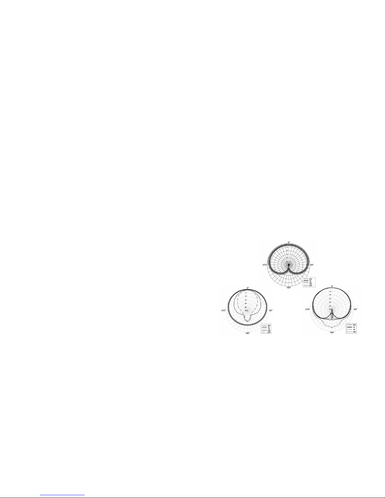
the microphone (off-axis). In gure 1a you will see a perfect cardioid polar
pattern which will pick up all frequencies uniformly at the front and the sides
of the microphone. Figure 1b shows the polar response of a typical conventional cardioid microphone. Notice the severe loss of high frequencies at
the sides of the microphone. Figure 1c is the near-perfect polar response
of an Earthworks microphone. The Earthworks microphone has a uniform
frequency response at the sides of the microphone that is within 3db of the
on-axis response at any frequency.
The Earthworks cardioid microphones will pick up sounds with nearly the same
delity at the front and the sides of the microphone. This is a remarkable
technical achievement and one that will provide incredible results for you.
Figure 1. Differences Between a Perfect, Conventional and an Earthworks Cardioid Microphone
(1b) Conventional Cardioid Microphone
(1c) Earthworks Cardioid Microphone
(1a) Textbook
Perfect Cardioid
Microphone
3
THE UNIQUE TECHNOLOGY INCORPORATED IN THE FLEXWAND™ WILL PROVIDE EXCEPTIONAL RESULTS. HOWEVER, THESE MICROPHONES DO NOT WORK LIKE CONVENTIONAL MICROPHONES, SO TO ACHIEVE THE GREATEST RESULTS, PLEASE TAKE THE
TIME TO READ THE NEXT FEW PAGES:
Page 4
4
Conventional Polar Response vs. Near-perfect Polar Response
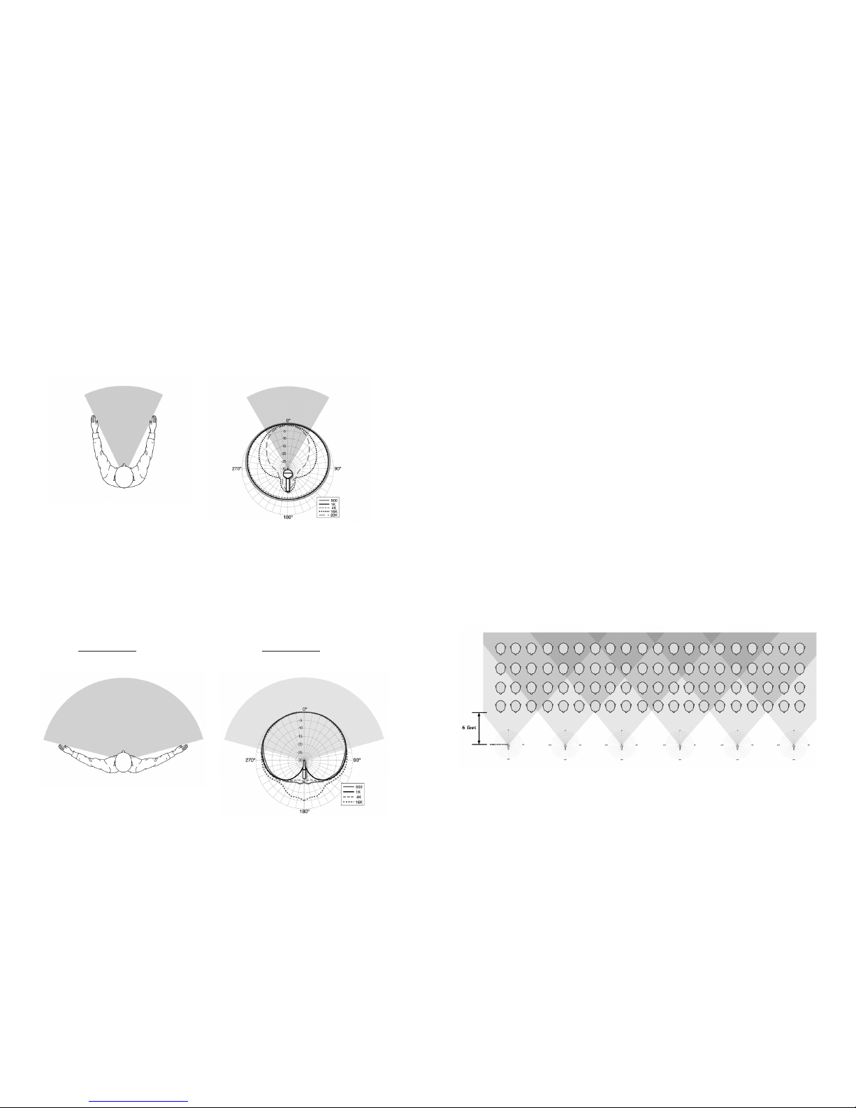
Before reading this information, if you were asked to spread your arms to indicate the width of the pick-up pattern of a conventional cardioid microphone, you
would probably indicate something like shown in Figure 2a. The actual polar
response of a typical conventional microphone (with full frequency response, i.e.
no loss of high frequencies) is illustrated in Figure 2b. Notice that the shaded
area in Figures 2a and 2b is virtually the same. Outside of the shaded area
there will be a substantial loss of high frequency information.
In contrast, if one were asked to spread their arms to indicate the width of the
pick-up pattern of an Earthworks cardioid microphone, they would indicate
something like shown in Figure 3a. The actual polar response of an Earthworks
cardioid microphone (with full frequency response, i.e. no loss of high frequencies) is illustrated in Figure 3b. Again, notice that the shaded areas in Figures
3a and 3b are virtually the same. Notice on the Earthworks microphone (Figure
3b) that even outside the shaded area there is a very minimal change or loss
in the level of high frequency information.
Figure 3a. Typical pick-up area (with full frequency
response) of an Earthworks cardioid microphone
indicated by extending arms
Figure 3b. Typical polar pattern (with full frequency
response) of an Earthworks cardioid microphone
Figure 2a. Typical pick up area (with full frequency
response) of a conventional cardioid microphone
indicated by extending arms
Figure 2b. Typical polar pattern (with full frequency
response) of a conventional cardioid microphone
How Earthworks Near-perfect Polar Response Can Benet You
There are several ways near-perfect polar response can benet you.
1. Use of fewer microphones
2. Ability to place microphones closer to the sound source for more gain
before feedback
3. No spotlighting or highlighting
4. More rejection of sounds from the rear of the microphone
5. Instruments or singers on the sides of the microphone enjoy the same
quality as those in front of the microphone.
Fewer Microphones Required
The taller FW730 is recommended for use with choir, even though the FW430
Series is not, the following illustrations of choir use clearly show the advantages
of the FlexWand’s near perfect polar response. Referring to Figure 2b, notice
how narrow the pick-up pattern is on a conventional cardioid microphone. In
comparison, notice how much wider the pickup pattern is on the Earthworks
cardioid microphone (Figure 3b). Keep in mind that the shaded areas in these
gures indicate the area where you can obtain the full frequency response of
the microphone without a signicant loss of high frequencies.
Conventional microphones (Figure 2b) only provide a narrow window (or area)
in which they can pick up sounds with full frequency response. Figure 4 below,
shows an 80-voice choir miked with conventional microphones. It takes 6 conventional microphones, placed 6 feet in front of the choir, to adequately cover
the choir with the full frequency response of the microphones.
In contrast, the near-perfect polar response of Earthworks cardioid microphones provide a wider pickup pattern (or area) where you can obtain the full
frequency response of the microphones. Figure 5 on the following page, is the
same 80-voice choir is covered using only 3 Earthworks cardioid microphones.
Figure 4. An 80-voice choir miked with 6 conventional microphones at 6 feet
5
Page 5
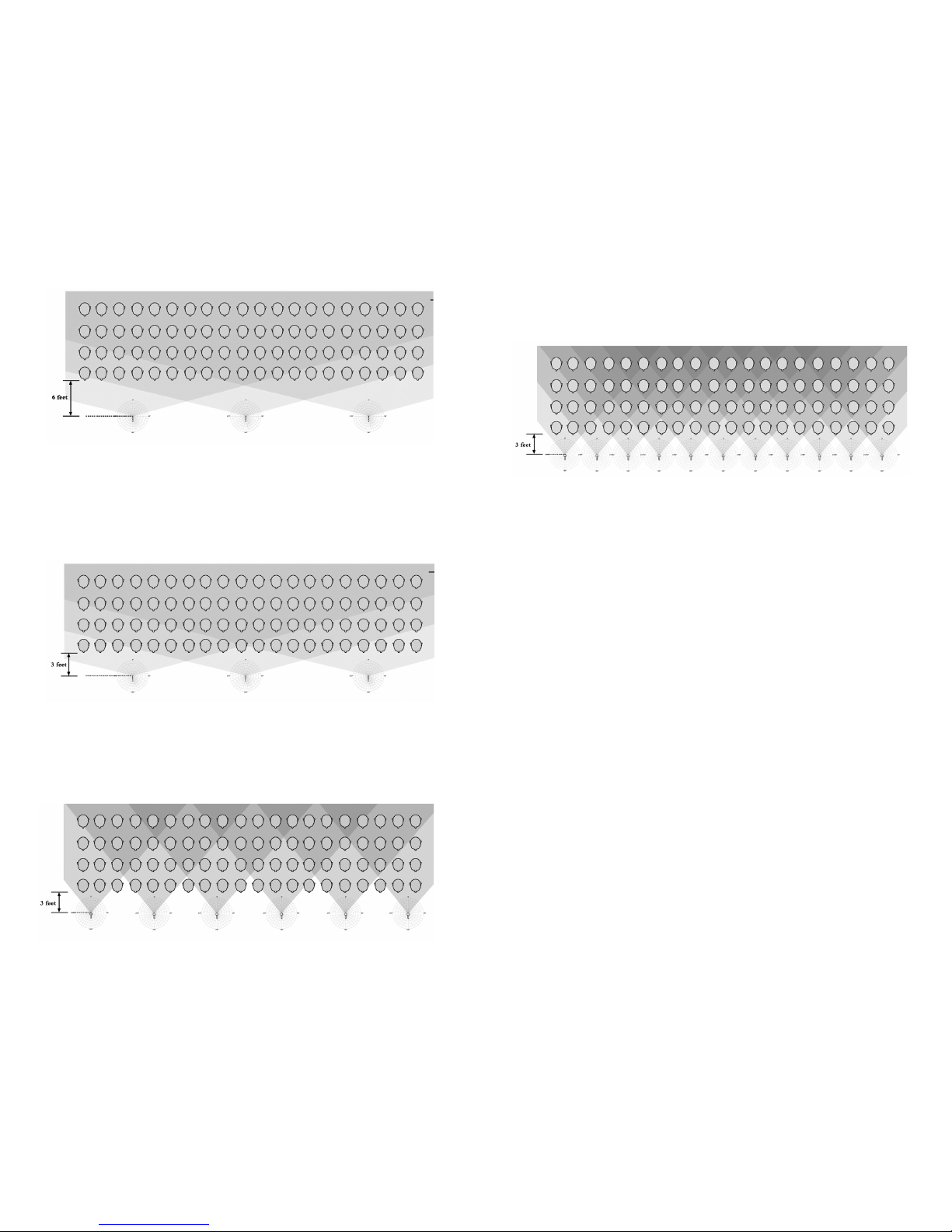
Figure 7. An 80-voice choir miked with 6 conventional microphones at 3 feet
Closer Miking Provides Additional Gain Before Feedback
Seasoned sound engineers know that placing a microphone closer to the sound
source will result in additional gain before feedback. Figure 6 below, shows the
same 80-voice choir miked with 3 Earthworks cardioid microphones, however,
notice that the microphones are placed 3 feet in front of the choir rather than
at 6 feet as indicated in Figures 4 and 5.
In contrast, Figure 7 shows the same choir miked with 6 conventional cardioid
microphones placed 3 feet in front of the choir. Notice the blank coverage spots
in the pick-up area. This illustrates that placing conventional microphones 3
feet in front of the choir would require even more microphones to adequately
cover the choir.
Figure 5. An 80-voice choir miked with 3 Earthworks microphones at 6 feet
Figure 6. An 80-voice choir miked with 3 Earthworks microphones at 3 feet
6
Figure 8 below, shows that it would actually take 12 conventional cardioid microphones to provide the same coverage as 3 Earthworks cardioid microphones,
when placed 3 feet in front of the choir.
Three characteristics of Earthworks microphones will provide more gain before
feedback: (1) Smooth off-axis response, (2) picking up far less sound from
the rear of the microphone and (3) wider usable polar-response that allows
microphones to be placed closer to the source. Each of these characteristics
will provide more gain before feedback, however, when you have all 3 it is
somewhat remarkable.
The near-perfect polar response provides a smooth off-axis response in addition
to a much wider pick-up pattern with the full frequency response of the microphone. With a wider pick-up pattern, the microphone can be moved closer to
the source (in this case singers) and obtain even more gain before feedback.
Spotlighting
Conventional microphones typically have problems with highlighting or spot-
lighting when used on choirs. This is caused by the signicant changes in
frequency response of sounds that are picked up off-axis. This phenomenon
will cause singers in a given frequency range to sound louder than others not
in that frequency range. This causes certain singers to stick out above the rest
making it difcult to achieve a good balance between all of the voices in the
choir. In contrast, the uniform off-axis response of Earthworks microphones
greatly reduces this phenomenon allowing a uniform balance of choir voices
to be achieved much easier.
Rejection of Sounds Behind the Microphone
A textbook perfect cardioid microphone will pick up sounds uniformly at the
front and sides of the microphone. However, the level (in dB) on the sides of
the microphone will be slightly less (as much as 6dB). Even though the level
at the sides of the microphone may be lower, the frequency response should
remain uniform (i.e. no loss of high frequencies). The textbook perfect cardioid
microphone is very dead at the rear of the microphone. The polar response
of a perfect cardioid microphone is shown in Figure 9a. Notice that at 180
degrees the level is down 30 dB or more.
Figure 8. An 80-voice choir miked with 12 conventional microphones at 3 feet
7
Page 6
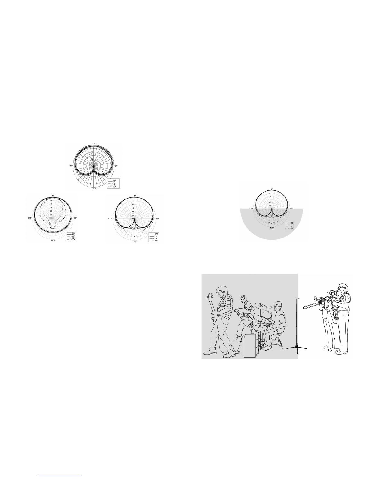
This is what provides the directional characteristics of a cardioid microphone,
in that it will pick up at the front and the sides and picks up far less at the
rear, therefore making the microphone directional. However, this is textbook
theory. This is much different in practice with real (imperfect) microphones
used in the real world.
Figure 9b shows the polar response of a typical conventional cardioid microphone. Notice at 500Hz, 1kHz and 4kHz the pick-up pattern is almost an omni
pattern, however, these three frequencies are down 10dB in level in reference
to their level at the front of the microphone (0 degrees). In contrast 16kHz
and 20kHz are down 15dB at the rear of the microphone. We need to look
at one important fact. Which frequencies are most audible, 500Hz to 4kHz,
or 16kHz to 20kHz? Without question the frequencies between 500Hz and
4kHz are vastly more audible or predominant than those between 16kHz and
20kHz. This shows that the typical conventional microphone in Figure 9b will
be somewhat less sensitive at the rear of the microphone, but by only about
10dB in the frequency range between 500Hz and 4kHz.
Looking at the Earthworks cardioid polar response in Figure 9c shows that it
has far more rejection in 500Hz to 4kHz frequency range at the rear, than the
conventional microphone shown in Figure 9b. In Figure 9c, see that 1kHz is
down by 30dB or more, while 500Hz and 4kHz are down 15dB. Also notice
that 16kHz and 20kHz are only down 5dB to 10dB. But remember that these
high frequencies are far less audible than those between 500Hz and 4kHz.
(9b) Conventional Cardioid Microphone
(9c) Earthworks Cardioid Microphone
Figure 9. Differences in the Rear Polar Response Between a Perfect,
Conventional and an Earthworks Cardioid Microphone
(9a) Textbook Perfect
Cardioid Microphone
8
What we have reviewed so far is technical information shown on charts and
graphs. Now lets look at what happens in the actual use and application of
these two types of cardioid microphones. If you were to take the typical conventional cardioid microphone in your hand and talk into the front of the mic
and while you are talking, rotate the microphone 180 degrees and talk into
the rear of the microphone, you would notice some reduction in the audible
level of your voice. In contrast, if you were to do the same exercise with an
Earthworks cardioid microphone, when you started talking into the rear of the
microphone your voice would be nearly inaudible. This practical demonstration
shows how dead the Earthworks cardioid microphones are at the rear. As a
general guideline, you can consider the coverage area from 90º, 180º to 270º
the dead zone of an Earthworks cardioid microphone as illustrated in Figure 10.
When miking choirs with an orchestra or band in front of the choir, the rear
rejection of sounds from an Earthworks cardioid can be a real benet. When
positioning the Earthworks microphone, make sure that the rear of the capsule
is facing the direction of the orchestra or band as shown in Figure 11.
9
Figure 10. Rear Polar Response of an Earthworks Cardioid Microphone
Figure 11. Proper Positioning of an Earthworks Cardioid Microphone
with an Orchestra or Band behind the Microphone
CORRECT POSITIONING microphone head perpendicular to
oor for maximum isolation
from a band or orchestra
Page 7
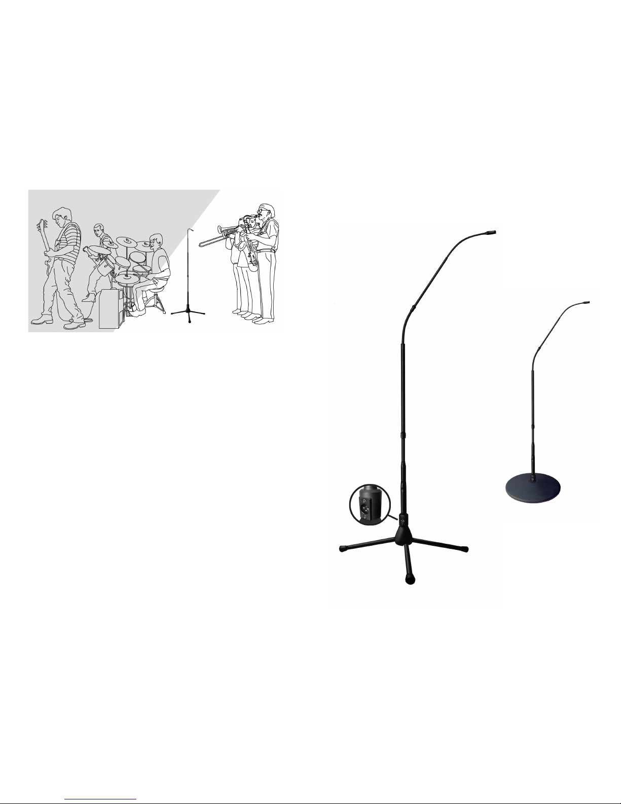
Figure 13
The FW430TPB FlexWand™ Elements
30kHz
Microphone head
Mini-Flex
Sleeve
Clutch
Wand
0.25” in
Diameter
Sleeve
Mating
Coupler
Large
Flex
Stand
0.75” in
Diameter
Microphone
Electronics
Section
XLR
Connector
11
Model FW430 with 12 lb.
Cast Iron Base
(image not shown to scale)
Model FW430TPB
with Tripod Base
Notice in Figure 12 what happens if the rear of the Earthworks cardioid microphone is not positioned toward the orchestra or band.
OBTAINING A GREATER UNDERSTANDING THE FlexWand™
As you have just read, the near-perfect polar response of the FlexWand™
provides you with many advantages over conventional microphones, not to
mention the dramatic increase of delity with a High Denition Microphone™.
You can easily place the FlexWand™ two or three feet in front of a choir or vocal group and achieve outstanding results with incredible sound quality and a
substantial increase in gain before feedback. It is suggested that when mik-
ing choirs, that you use a high pass lter (low-cut) on your console and set it
somewhere in the 120Hz range. This will increase your gain before feedback
even more. You can also achieve more gain before feedback by boosting the
FlexWand™ with EQ at 1.5kHz and 5kHz. If this starts to sound too thin, you can
boost at 500Hz to add some warmth and bottom end. The information in this
manual should provide you with a good basic understanding of the FlexWand™
and it’s unique technology. As you continue to use the FlexWand™ you will nd
additional ways to improve your results in using this unique microphone system.
IDENTIFICATION OF THE FLEXWAND™ ELEMENTS
In this manual we will refer to the various elements of the FlexWand™ System. In Figure 13 all of the elements of the FlexWand™ System are identied. Please review this information:
Figure 12. Improper Positioning of an Earthworks Cardioid Microphone
with an Orchestra or Band behind the Microphone
INCORRECT POSITIONING
microphone head at an angle
to oor causes poor isolation
from the orchestra or band
10
Page 8
12
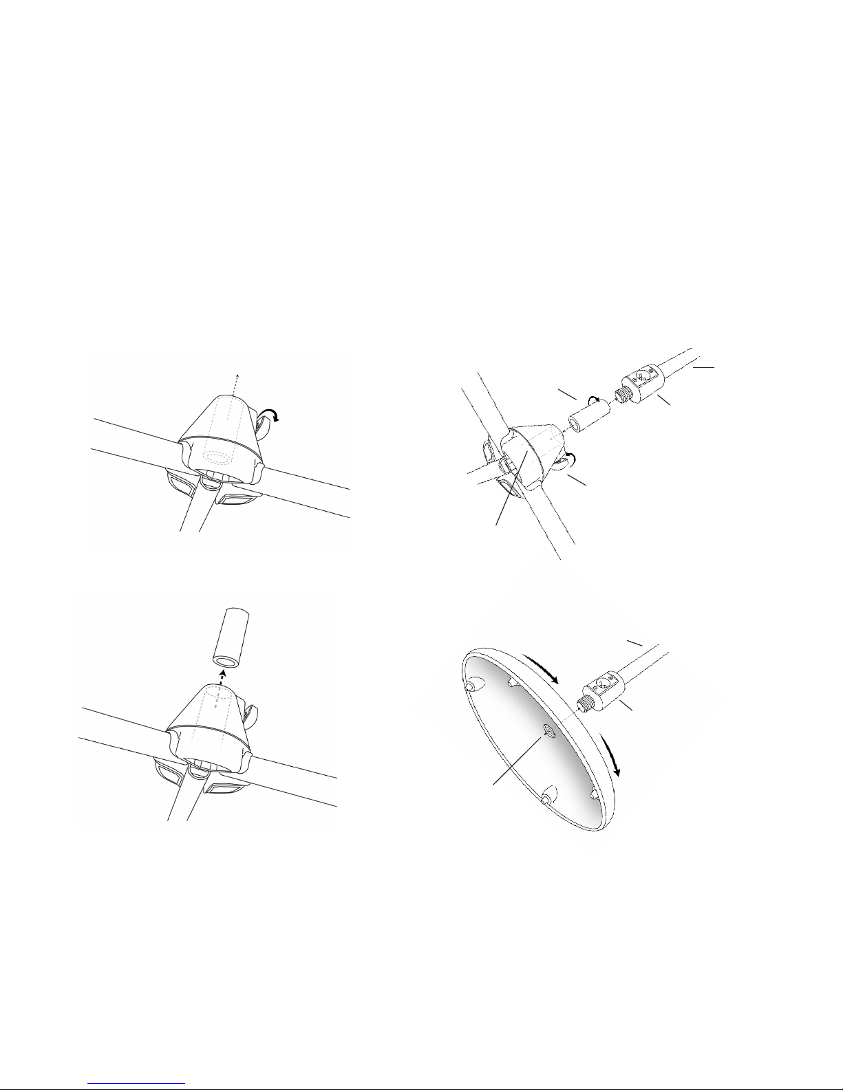
The FW430 FlexWand™ Comes in Two Versions
The FW430 comes with a 12 lb. cast iron base and
the FW430TPB comes with a collapsible tripod base.
The FW430TPB with a Tripod Base
has a metal sleeve stored
inside the tripod base,
as shown in Fig. 14a
Loosen the set-screw
and remove the metal
sleeve from inside the
tripod base.
Remove the metal sleeve
from inside the tripod base
as shown in Fig. 14b
Figure 14a
Figure 14b
(C)
metal sleeve
(A)
FlexWand
Stand Sec-
tion
(D)
Hole in
Tripod Base
(E)
Setscrew
To assemble the FW430TPB, first
screw the metal sleeve (C) onto
the threads on the bottom of the
FlexWand until the metal sleeve is
screwed on tight. Then pick up the
FlexWand by holding the stand section (A) or the XLR section (B) and insert the metal sleeve into the hole on
the tripod base (D). Push the sleeve
all the way down and then tighten the
setscrew (E).
The FW430 FlexWand™ Comes in Two Versions
The FW430 comes with a 12 lb. cast iron base and
the FW430TPB comes with a collapsible tripod base.
Connecting the Tripod Base to the FW430TPB
When screwing the FW430 in
the cast iron base, rst place
the cast iron base on the oor.
Then, by holding the stand
section (A), carefully rotate
the FlexWand into the threaded hole (C) in the cast iron
base (at least 2 full turns).
Next, wrap your hand around
the XLR connector section
(B), pick up the combined
FlexWand and base, then spin
the base until it is snug. Do
not over tighten. Be careful
that the microphone head
does not bang into something
during this process.
Connecting the Cast Iron Base to the FW430
(C)
Hole in
Cast Iron
(A)
FlexWand
Stand Sec-
Figure 15. Connecting the
tripod base to the FW430TPB
Figure 16. Connecting the
cast iron base to the FW430
(B)
XLR
Section
(B)
XLR
Section
13
Page 9
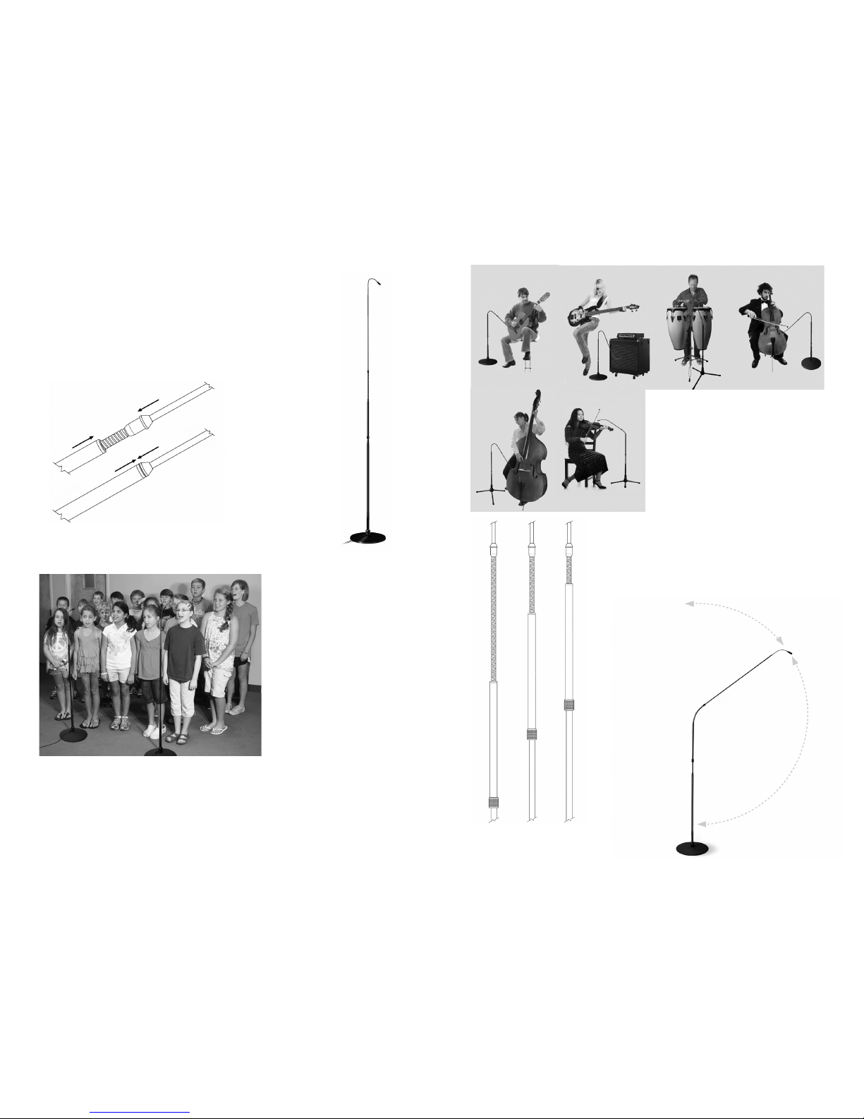
USING THE FLEXWAND™ AT MAXIMUM HEIGHT
There may be some applications where you will probably
want to have the FlexWand™ at its maximum height of 4.7
feet. This is easily achieved by pointing the wand straight up
and then loosen the clutch and slide the sleeve up until it
mates into the “sleeve mating coupler.” Make sure it is all the
way up and firmly seated over the mating coupler (see Figure
17). This will insure
that the FlexWand™
is perfectly straight
up and down from all
directions. Then position the microphone
head to any position
that you desire with
the mini-flex at the
end of the wand (see
Figure 18).
USING THE FLEXWAND™ AS A BOOM
In the “boom mode” the FlexWand™ can mike anything just like a conventional microphone on a boom stand. This can be used when you want the
FlexWand™ microphone lower for such applications as small vocal groups
or vocal solos. (see Figure 20).
14
Figure 17. Seating the Sleeve
over the Mating Coupler
Figure 18. Positioning
the Microphone Head
with the FlexWand at
Maximum Height
Figure 19. FW430 series used in miking
a children’s choir at maximum height.
The near-perfect cardioid
pattern of the FlexWands
allow placing the microphone heads as close
as 18 inches in front
of the singers and still
have a uniform, balanced
pickup, with no highlighting or spotlighting of the
singers directly in front
of the microphones. You
could never do this using
conventional mics. See
Figure 21-a. Sleeve all the way down
21-b, Sleeve half-way up
21-c Sleeve three-fourths of the way up
Figure 22. Using the
Wand as a boom.
21-a 21-b 21-c
15
When using the “boom mode,” the
clutch should be loosened and the
sleeve should be slid down so it
only covers about half of the large
flex, then tighten the clutch. By
doing this, the flex section will be
much more rigid than if the sleeve
were slid all the way down.
You might want to experience this for yourself by
first loosening the clutch and sliding the sleeve all
the way down (tighten the clutch) and then position the wand at a 45 degree angle (see Figure
Figure 20. Various applications of
using the FlexWand in boom mode
Page 10
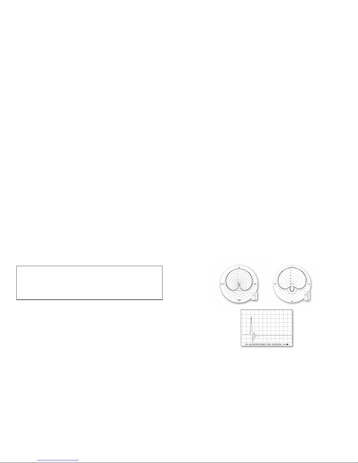
FW430 (Cardioid) & FW430/HC (Hypercardioid) with cast iron base
FW430TPB (Cardioid) & FW430/HC-TPB (Hypercardioid) with tripod base
Frequency Response: 30Hz to 30kHz ±2dB @ 1 foot (30cm)
Polar Pattern: Cardioid or Hypercardioid
Sensitivity: 20mV/Pa (-34dBV/Pa)
Power requirements: 48V Phantom, 10mA
Max Acoustic Input: 139dB SPL
Output Connector: Female XLR-3 (pin 2+)
Min Output Load: 600 ohms between pins 2 & 3
Noise: 16dB SPL equivalent (A weighted)
Positioning Range: From 10 in (254mm) to 4.7 ft. (1.4m) with tripod base;
and 5 in (127mm) to 4.35 ft. (1.3m) with the cast iron base.
Dimensions: Stand 52” long (1.32m), Cast Iron Base 12” (30.48cm) in diameter,
1.1” (2.7cm) high; Tripod Base 23” (58cm) footprint, 6” (15.2cm) high
Color: Stand, ex & wand - black; cast iron base - dark gray; tripod base - black
Unit Weights: Stand 2 lbs. (.9 kg), Cast Iron Base 12.6 lbs. (5.7kg), Tripod Base
1.6 lbs. (0.73kg)
FW430
Polar Pattern
FW430/HC
Polar Pattern
FW430, FW430/HC Impulse Chart
FW430 FLEXWAND™ SERIES SPECIFICATIONS
17
21a). Now position the wand at several angles greater and less than 45
degrees and see how it feels.
Then loosen the clutch again and cover only half of the large flex then
tighten the clutch (see Figure 21b). Now position the wand at several angles at greater and less than 45 degrees (see Figure 22) to see how the
large flex is much more rigid.
The large flex can be made even more rigid by sliding the sleeve up to
cover three-fourths of the large flex (see Figure 21c). These adjustments
are ideal when you want to position the wand at any position between
straight up to a 90 degree angle. If you want to go more than 90 degrees,
you will need to re-position the sleeve to uncover more, or all of the large
flex, thereby allowing it to be positioned between 90 degrees to nearly
180 degrees.
The highly versatile FlexWand™ High Definition Microphone System is a
uniquely creative tool that will provide outstanding sonic results for virtually any recording or live sound application. It is low profile with no visible
wires above floor level provides a clean sleek look that will not visually
impair or detract from the musical or theatrical performance. The quality
construction of the FlexWand™ will provide you with years of exceptional
service. If you have any questions, please contact Earthworks Customer
Service Department at 603-654-6427, ext. 119.
16
FIFTEEN-YEAR WARRANTY
All Earthworks® products (excluding accessories) carry a fifteen-year limited
warranty (parts and labor). If you have any problems with your Earthworks
products, please contact our warranty/repair department by email at:
[email protected] or by telephone at (603) 654-2433, ext 119.
 Loading...