

Page 1

MWB1300
Wireless Video Extender Kit
User’s Guide
Version 3.12.100
Design. Build. Ship. Service
Page 2

Table of Contents
1 Preface .................................................................................................................................................... 4
Who should use this guide .......................................................................................................... 4
Support Information..................................................................................................................... 4
2 Introduction .......................................................................................................................................... 5
3 Knowing your MWB1300 Kit............................................................................................................. 7
Package Contents .......................................................................................................................... 7
Hardware Overview..................................................................................................................... 7
MWB1305 connections............................................................................................................ 8
MWS1000 connections ............................................................................................................ 9
Front Panel and LED Status Lights..................................................................................... 10
4 Setting Up your MWB1300 Kit........................................................................................................ 14
Powering Up your devices......................................................................................................... 15
Pairing your Devices................................................................................................................... 17
Placing and connecting your devices....................................................................................... 18
Changing Your Computer’s IP Address.................................................................................. 21
5 Management - Getting Started ........................................................................................................ 23
Logging into the MWB1305 Management Application......................................................... 24
Navigating the MWB1305 Management Application............................................................ 25
6 Managing the MWB1305 Device..................................................................................................... 27
Configuring the MWB1305 Device........................................................................................... 28
Defining Network Settings................................................................................................... 28
Defining Wireless Settings.................................................................................................... 30
Defining QoS Settings ........................................................................................................... 33
Defining Security Settings .................................................................................................... 35
Defining WPS Settings .......................................................................................................... 39
pg. 2 Copyright © 2009 Flextronics Special Business Solutions | Design. Build. Ship. Service
Page 3

Performing Administration.................................................................................................. 41
Monitoring the MWB1305 Device............................................................................................. 45
Viewing System and Station Parameters............................................................................ 45
Viewing Station Statistics ..................................................................................................... 48
Viewing Multicast Status...................................................................................................... 50
A Updating the MWS1000..........................................................................................................................53
B Troubleshooting MWB1300 Kit............................................................................................................56
C Technical Specifications.........................................................................................................................58
D Regulatory Compliance Information...................................................................................................59
Europe – EU Declaration of Conformity.................................................................................. 59
FCC Requirements for Operation in the United States.......................................................... 59
Federal Communication Commission Statement ............................................................. 59
FCC Warning.......................................................................................................................... 60
FCC RF Radiation Exposure Statement.............................................................................. 60
Industry Canada (IC) Statement ............................................................................................... 60
Copyright © 2009 Flextronics Special Business Solutions | Design. Build. Ship. Service pg. 3
Page 4

Preface
Welcome to the Wireless Video Extender solution set from Flextronics. The User’s Guide
will help you to understand the Wireless Video Extender solution, how to install it,
configure it and troubleshoot problems.
Who should use this guide
This User’s Guide assumes that the reader has basic to intermediate computer and internet
skills. All the basic computer networking, Internet, and other information required to
configure the home network and the devices is provided herein.
Support Information
Flextronics Special Buisness Solutions
Hatasia 1 St Ramat Gavriel Ind. Zone .
P.O. Box 23108
Migdal Haemek
Israel
Tel.: +972-4-644-8212
Fax: +972-4-604-0850
pg. 4 Copyright © 2009 Flextronics Special Business Solutions | Design. Build. Ship. Service
Page 5

Introduction
The Wireless Video Extender solution set enables service providers and consumers to
quickly and simply deploy wireless home networks that can securely deliver multiple
streams of carrier-quality SDTV and HDTV, and any other multimedia content throughout
the home. The solution is optimized toward Quality of Experience (QoE) and performance
consistency in both capacity and coverage.
The Wireless Video Extender solution set includes a “Celeno-Powered” MWB-1305
“Access Point” and a MWS-1000 “Client” which enable distribution of high-definition
video streams from one central location to a TV set in the house without replacing existing
routers, gateways, set top boxes or laying out new cables across the house.
1
Copyright © 2009 Flextronics Special Business Solutions | Design. Build. Ship. Service pg. 5
Page 6
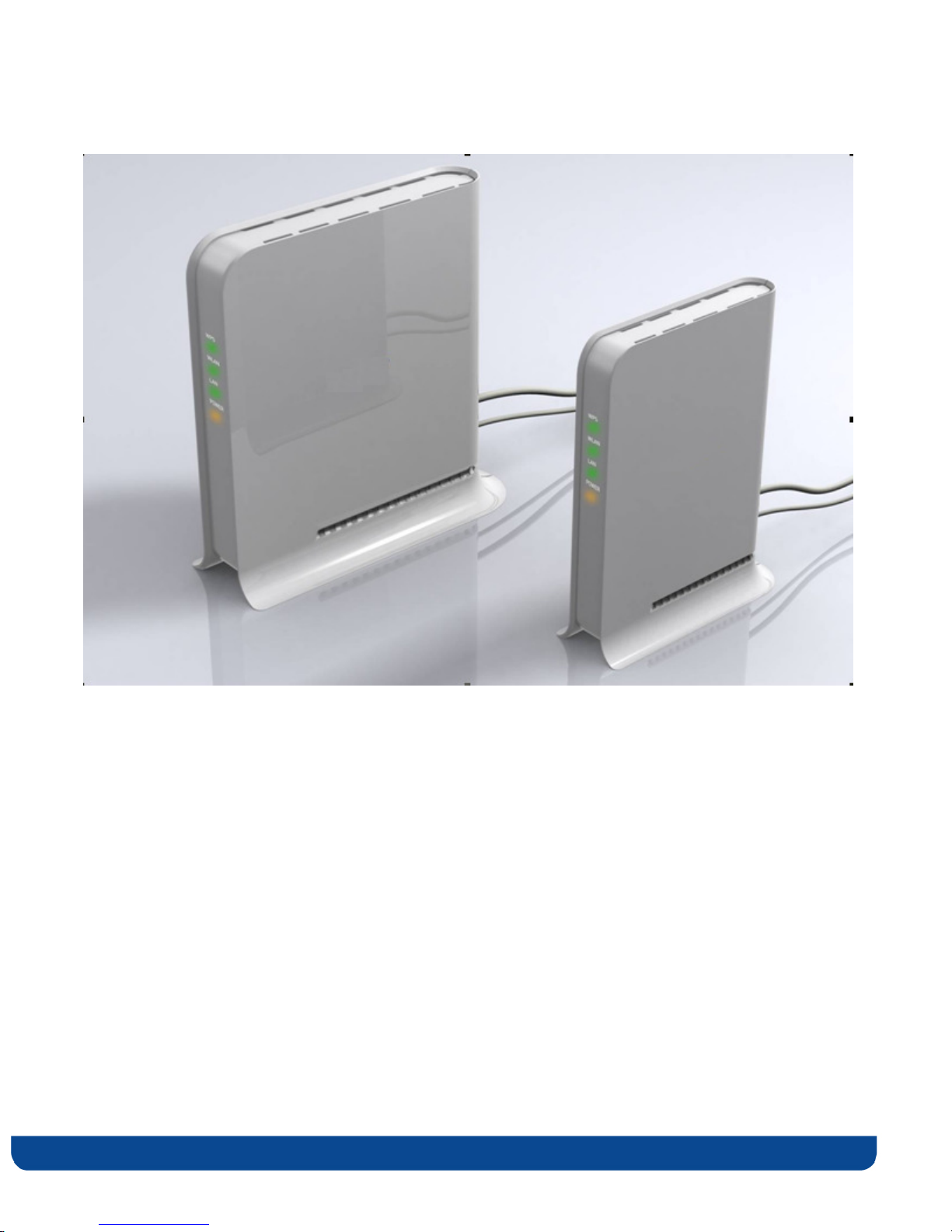
Figure 1 MWB1300 Kit
pg. 6 Copyright © 2009 Flextronics Special Business Solutions | Design. Build. Ship. Service
Page 7

Knowing your MWB1300 Kit
Package Contents
Your MWB1300 Kit contains the following items:
1. MWB1305 Wireless Video Extender “Access Point”
2. MWS1000 Wireless Video Extender “Client”
2
3. Two CAT5 cables
4. 1 Power Transformer for the MWB1305 device
5. 1 Power Transformers for the MWS1000 device
6. Quick Installation Guide
Hardware Overview
The MWB1300 Kit is comprised from a MWB1305 access point device and a MWS1000
client device .
The MWB1305 is powered by Celeno’s CL1300 WiFi chipset that employs sophisticated
algorithms and techniques such as implicit Beam Forming to reliably stream High
Definition video to any location in the home. The MWB1305 connects to the video source
that can be a gateway or a cable/DSL modem.
The MWS1000 is a standard “off the shelf” WiFi client device. The MWB1000 connects to
the video receiving set top box device.
The MWB1300 devices has been designed to be placed on a desktop. All of the cables exit
from the rear of the devices. The status display LEDs are located at the front of the devices
and are easily visible.
Copyright © 2009 Flextronics Special Business Solutions | Design. Build. Ship. Service pg. 7
Page 8
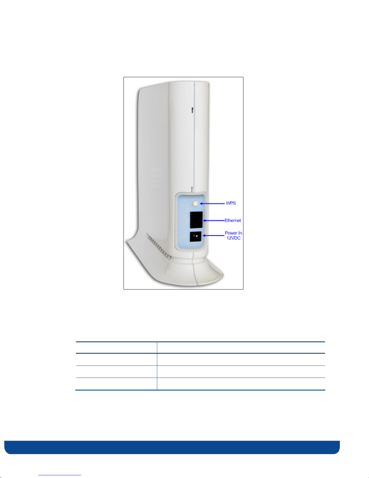
MWB1305 connections
Figure 2: MWB1305 – Rear Panel
The following table describes the connectors on the rear panel of the MWB1305 device:
Table 1: MWB1305 Rear Panel – Connectors
Name Description
Ethernet Data and Management Ethernet port.
WPS Wireless Protected Setup(WPS) button.
Power In DC power input. 12 VDC.
pg. 8 Copyright © 2009 Flextronics Special Business Solutions | Design. Build. Ship. Service
Page 9
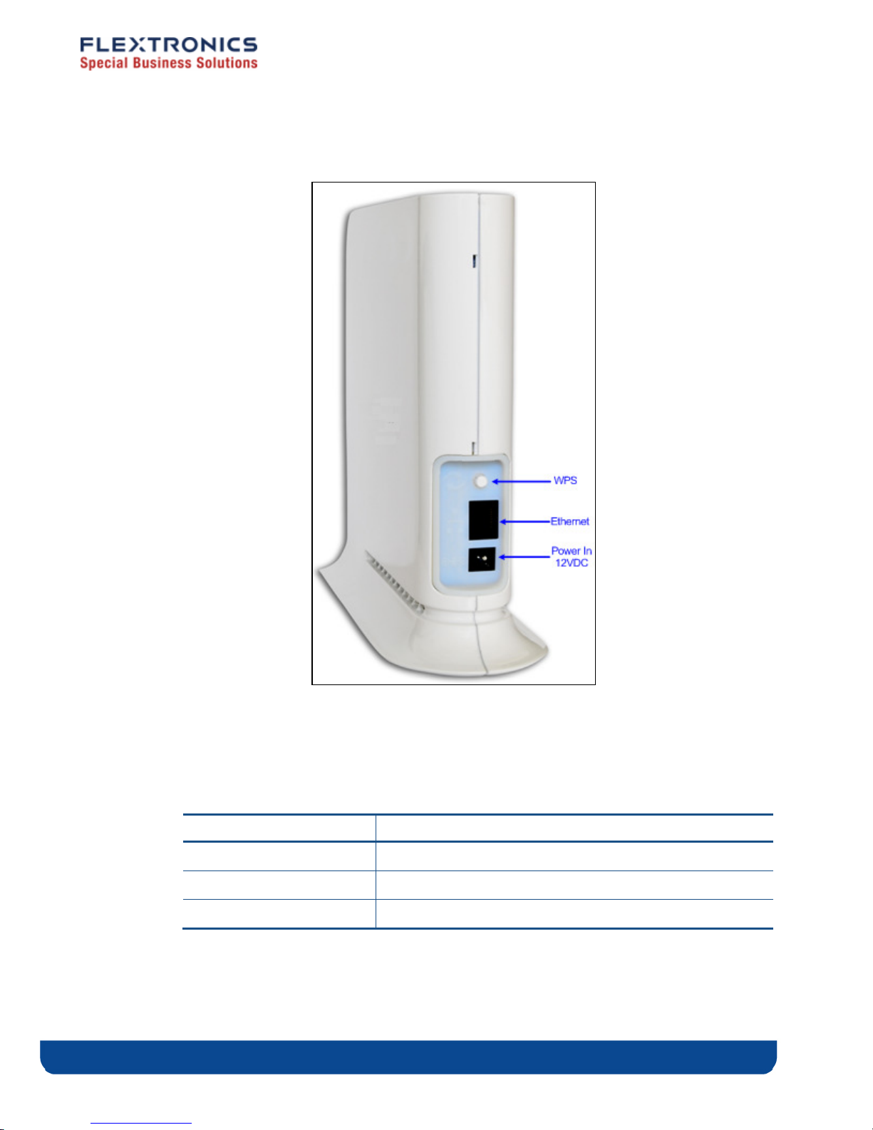
MWS1000 connections
Figure 3: MWS1000 – Rear Panel
The following table describes the connectors on the rear panel of the MWS1000 device:
Table 2 - MWS1000 Rear Panel – Connectors
Name Description
Ethernet Data and Management Ethernet port.
WPS Wireless Protected Setup(WPS) button.
Power In DC power input. 5 VDC.
Copyright © 2009 Flextronics Special Business Solutions | Design. Build. Ship. Service pg. 9
Page 10
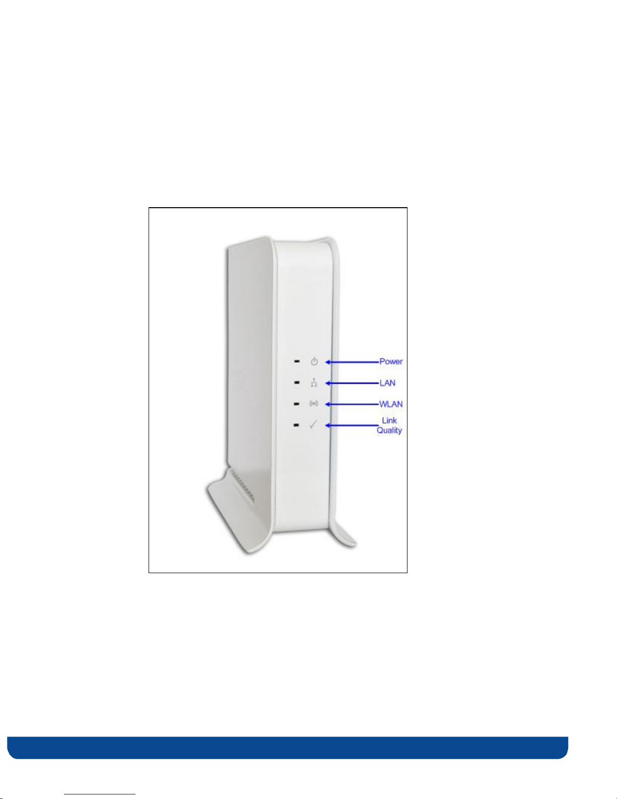
Front Panel and LED Status Lights
Figure 4 - MWB1305/ MWS1000 – Front Panel shows the front view of the MWB1305 and
MWS1000 devices.
pg. 10 Copyright © 2009 Flextronics Special Business Solutions | Design. Build. Ship. Service
Figure 4 - MWB1305/ MWS1000 – Front Panel
Page 11

The following table describes the LED indications on the front panel of the MWB1305
Device.
Table 3 - MWB1305 LEDs
Name Color Description
Solid Green The device is powered on. Power
Off The device is powered off.
Solid Green The LAN port is connected and has a link. LAN
Off The LAN port is either not connected or has no
link.
WLAN
Link Quality
Solid Green At least one MWS1000 device is associated with
the MWB1305 AP.
Flashing Green WPS pairing is in progress. This is a temporary
state that lasts no longer then 2 minutes.
Off No MWS1000 devices are associated with the
MWB1305 AP.
Solid Green The wireless link conditions are excellent and all
of the associated MWS1000 devices can
consistently receive high definition video streams.
Flashing Green WPS pairing has finished successfully. This is a
temporary state that lasts for 30 seconds.
Solid Yellow The wireless link conditions are fair and all of the
associated MWS1000 devices can consistently
receive standard definition video streams, but at
least one associated MWS1000 device is unable to
consistently receive high definition video streams.
Flashing Yellow WPS pairing has failed. This is a temporary state
that lasts for 30 seconds.
Off The wireless link conditions are poor and at least
one associated MWS1000 device cannot receive
video at all.
Copyright © 2009 Flextronics Special Business Solutions | Design. Build. Ship. Service pg. 11
Page 12

The following table describes the LED indications on the front panel of the MWS1000
Device.
Table 4 - MWS1000 LEDs
Name Color Description
Solid Green The device is powered on. Power
Off The device is powered off.
Solid Green The LAN port is connected and has a link. LAN
Off The LAN port is either not connected or has no
link.
WLAN
Link Quality
Solid Green The MWS1000 device is associated with a
MWB1305 AP.
Flashing Green WPS pairing is in progress. This is a temporary
state that lasts no longer then 2 minutes.
Off The MWS1000 device is not associated with a
MWB1305 AP.
Solid Green The wireless link conditions are excellent and the
MWS1000 device can consistently receive high
definition video streams.
Flashing Green WPS pairing has finished successfully. This is a
temporary state that lasts for 30 seconds.
Solid Yellow The wireless link conditions are fair and the
MWS1000 device can consistently receive
standard definition video streams but not high
definition video streams.
Flashing Yellow WPS pairing has failed. This is a temporary state
that lasts for 30 seconds.
Off The wireless link conditions are poor and the
MWS1000 device cannot receive video at all.
pg. 12 Copyright © 2009 Flextronics Special Business Solutions | Design. Build. Ship. Service
Page 13

The following LED combinations describe special indications:
Combination – The Power LED is solid green, the LAN and WLAN LEDs are flashing
green and the link quality LED is flashing yellow. The flashing is simultaneous.
Description – The device is experiencing a severe malfunction. Please contact your service
provider or local dealer.
Combination – The Power LED is solid green, the LAN, WLAN and Link quality LEDs are
flashing green. The lashing is in sequence.
Description – The device is undergoing a software upgrade process.
“Do not unplug the device from the power outlet or reset it while software upgrade is in
progress”.
Copyright © 2009 Flextronics Special Business Solutions | Design. Build. Ship. Service pg. 13
Page 14

Setting Up your MWB1300 Kit
Setting up the system involves the following steps:
Powering up your devices
Pairing your devices
Placing and connecting your devices
After performing these steps, you can start streaming High Definition video through the
MWB1300 Kit.
Changing your computer’s IP address
After performing this additional step, you can use the MWB1305 Management Application
to configure and manage your MWB1305 device. (refer to Managing the MWB1305 Device
on page 27).
pg. 14 Copyright © 2009 Flextronics Special Business Solutions | Design. Build. Ship. Service
Page 15
Powering Up your devices
To power up the MWB1305 device:
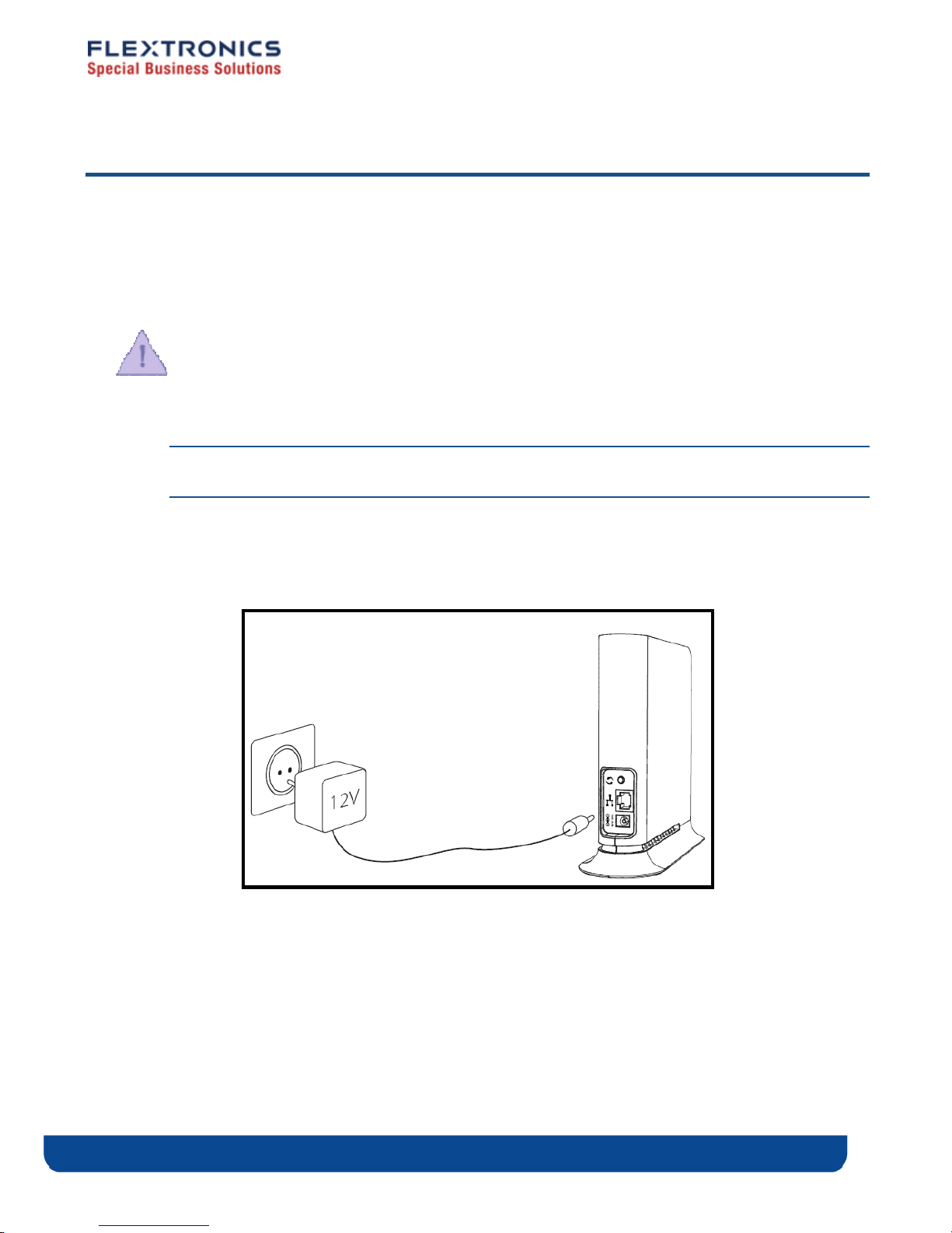
1. Plug in the 12V A/C adapter and connect it to the MWB1305 Access Point device.
Use the recommended AC/DC power adaptor which was supplied in the kit.
“Using a power supply with a different voltage rating then the one included with the
MWB1305 device will cause damage and void the warranty for this product”.
Note: There is no On/Off switch. Once you connect the power adapter, the MWB1305
device powers up.
2. Wait several seconds while the MWB1305 device performs a reset.
Figure 5- Powering up the MWB1305 Device
Copyright © 2009 Flextronics Special Business Solutions | Design. Build. Ship. Service pg. 15
Page 16
To power up the MWS1000 device:
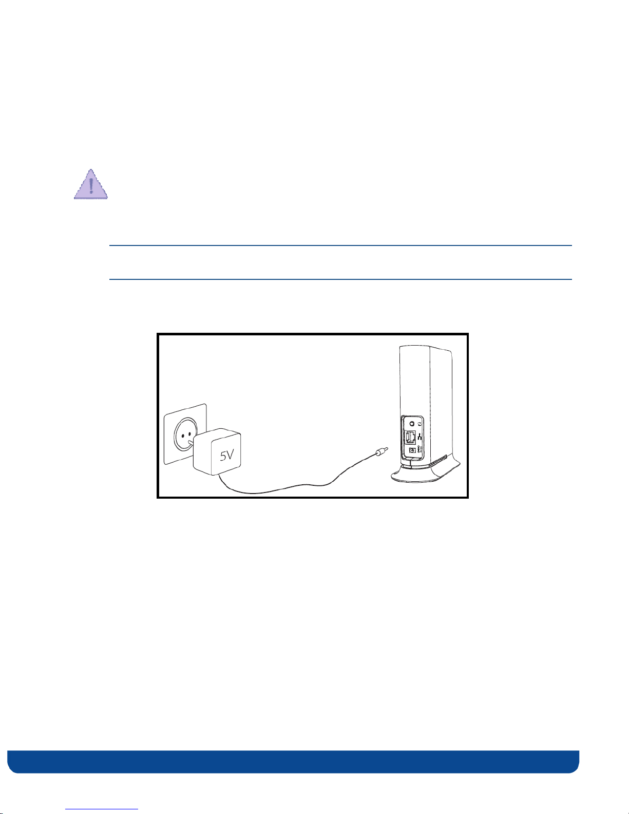
1. Plug in the 5V A/C adapter and connect it to the MWS1000 Client device.
Use the recommended AC/DC power adaptor which was supplied in the kit:
“Using a power supply with a different voltage rating then the one included with the
MWS1000 device will cause damage and void the warranty for this product”.
Note: There is no On/Off switch. Once you connect the power adapter, the MWS1000
device powers up.
2. Wait several seconds while the MWS1000 device performs a reset.
Figure 6 - Powering up the MWS1000 Device
pg. 16 Copyright © 2009 Flextronics Special Business Solutions | Design. Build. Ship. Service
Page 17
Pairing your Devices
Note: Consult with the quick installation guide that came with your kit to check if the
devices in your kit are already paired, in which case you can skip this step. .
1. Place the MWB1305 Access Point and the MWS1000 Client devices between 1 to 3
meters from each other.
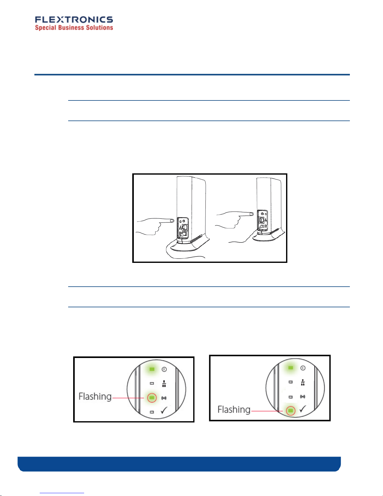
2. Pair the devices by pressing the WPS button on the MWB1305 and MWS1000 rear panel
for 5 seconds. You can release the button as soon as the WLAN LED begins flashing.
Figure 7 - Pairing the devices
Note: The WPS buttons should be pressed within 2 minutes period. The buttons can be
pressed in any order.
3. Wait for the pairing process to complete by watching the LEDs on the devices:
While pairing is in progress the WLAN LED is flashing green
After successful pairing the Link Quality LED is flashing green for 30 seconds.
Pairing is in progress Pairing has finished successfully
Copyright © 2009 Flextronics Special Business Solutions | Design. Build. Ship. Service pg. 17
Page 18
Placing and connecting your devices
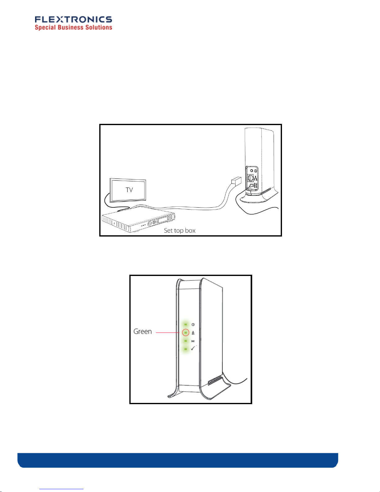
To place and connect your MWB1305 device:
1. Place the MWB1305 Access Point device on an easily-accessible surface near the home
gateway or Cable/DSL Modem.
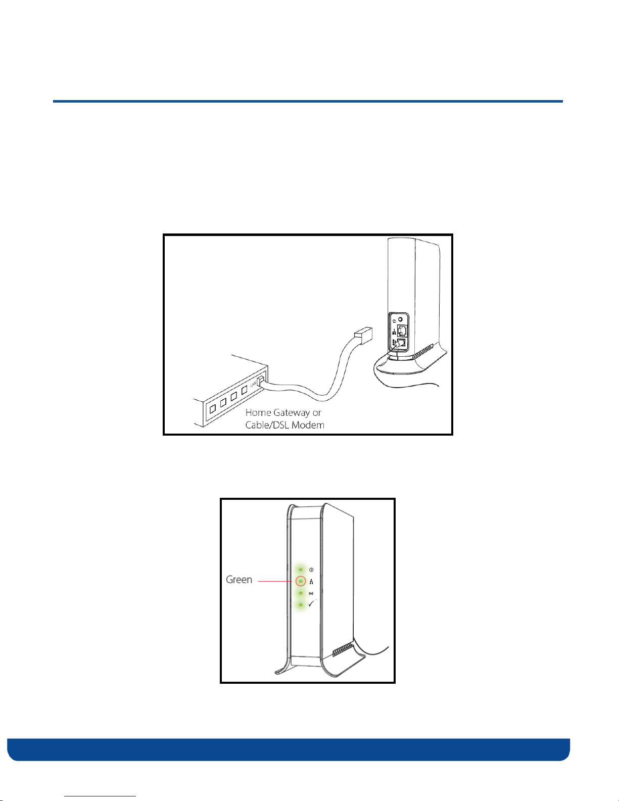
2. Plug one end of the Ethernet cable into the LAN port of the gateway device and the
other end into the Ethernet port of the MWB1305.
Figure 8 - Connecting and placing the MWB1305 device
3. Make sure that the LAN LED on the MWB1305 is turned on:
pg. 18 Copyright © 2009 Flextronics Special Business Solutions | Design. Build. Ship. Service
Page 19
To place and connect your MWS1000 device:
1. Place the MWS1000 Client device on an easily-accessible surface near the set top box.
2. Plug one end of the Ethernet cable into the LAN port of the set top box device and the
other end into the Ethernet port of the MWS1000.
Figure 9- Connecting and placing the MWS1000 device
3. Make sure that the LAN LED on the MWS1000 is turned on:
Copyright © 2009 Flextronics Special Business Solutions | Design. Build. Ship. Service pg. 19
Page 20
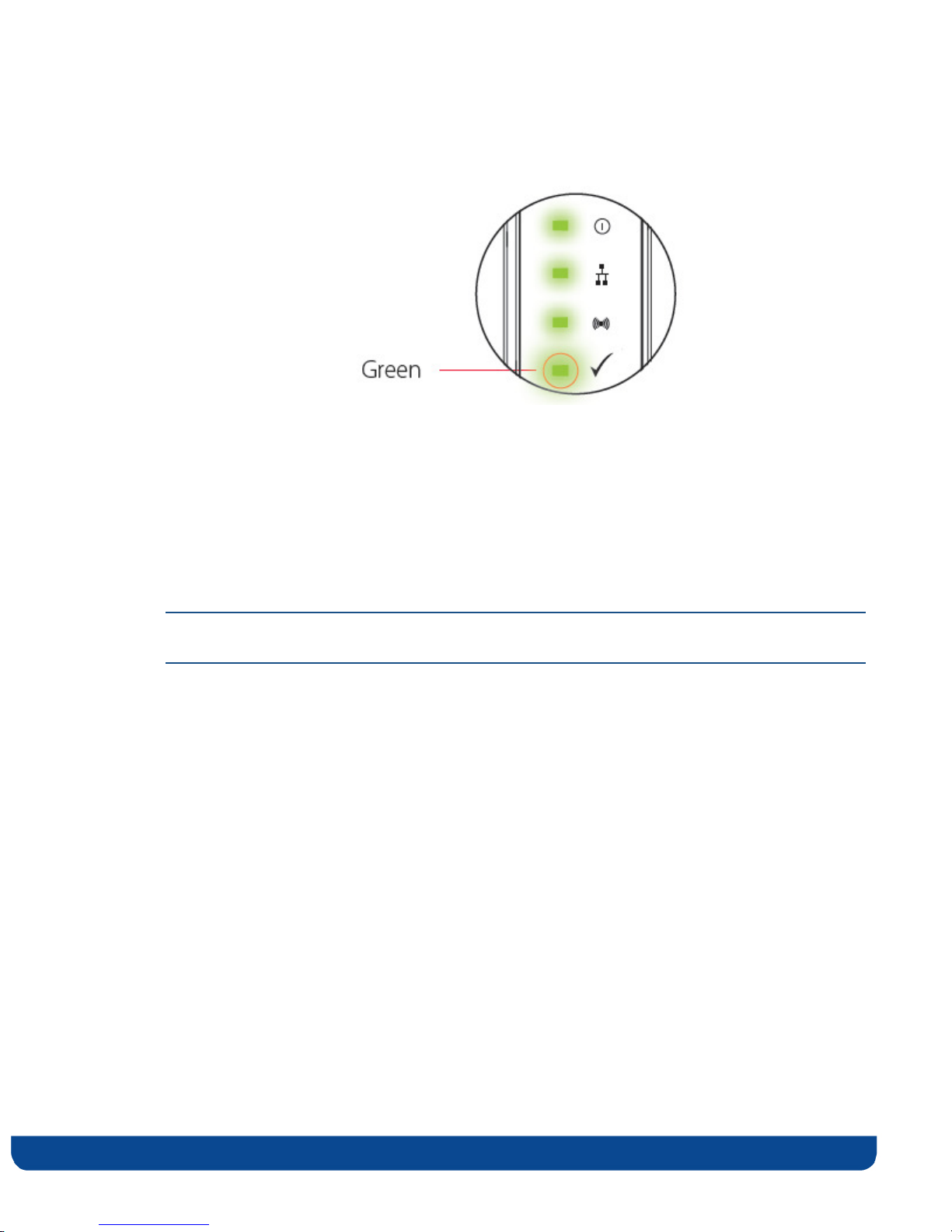
4. Make sure that the link quality LED is solid green:
If the link quality LED is solid yellow or turned off, try to reposition the device to a more
elevated location and as far as possible from large metallic objects.
Completing the installation:
You have finished installing your MWB1300 kit. To test your connectivity, turn on the TV
and set top box and watch any available channel.
Note: To install additional MWS1000 devices, repeat the above procedure for each new
MWS1000 device.
pg. 20 Copyright © 2009 Flextronics Special Business Solutions | Design. Build. Ship. Service
Page 21
Changing Your Computer’s IP Address
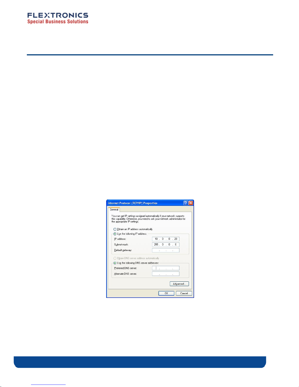
In order to connect your management computer to the MWB1305 device, you must change
the IP address of your computer so that it is on the same subnet as the MWB1305 device
(by default 10.x.x.x). Since this disconnects your computer from your computer network,
you may need to restore this setting later.
To change the IP address of your computer:
1. Connect an Ethernet cable between the Ethernet port of the MWB1305 device and the
Ethernet port of your computer.
2. From your computer’s desktop, click Start > Settings > Network Connections and
double-click the LAN connection for your computer network. The Local Area
Connection Status window appears.
3. From the General tab, click Properties. The Local Area Connection Properties window
appears.
4. Select Internet Protocol (TCP/IP) and click Properties. The Internet Protocol (TCP/IP)
Properties window appears.
Figure 10: Internet Protocol (TCP/IP) Properties Window
5. Make a note of the current settings in this window. You will need to know these
settings when reconnecting your computer to your computer network.
Copyright © 2009 Flextronics Special Business Solutions | Design. Build. Ship. Service pg. 21
Page 22

6. Check Use the following IP address and type an IP address in the same subnet as the
MWB1305, in the following format: 10.x.x.x. Be sure to use an IP address that is
different from the IP address of your MWB1305 device which is 10.0.0.2 by default.
7. Click OK to save the information and close the Internet Protocol (TCP/IP) Properties
window.
8. Click OK to close the Local Area Connection Properties window.
9. Click Close to close the Local Area Connection Status window.
pg. 22 Copyright © 2009 Flextronics Special Business Solutions | Design. Build. Ship. Service
Page 23

Management - Getting Started
The MWB1305 Management Application is a web-based tool that enables you to manage
and configure your MWB1305 device. This chapter describes how to navigate through the
MWB1305 Management Application:
Note: Ensure that you have connected an Ethernet cable between your computer and the
MWB1305 device.
3
Copyright © 2009 Flextronics Special Business Solutions | Design. Build. Ship. Service pg. 23
Page 24
Logging into the MWB1305 Management Application
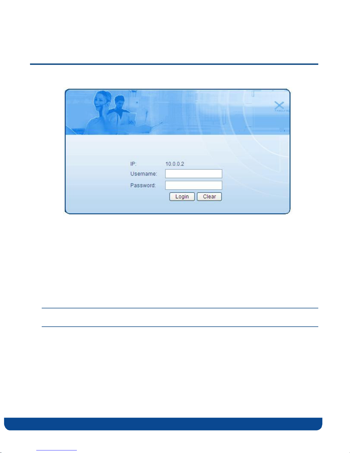
Figure 11 - MWB1305 Management Application – Login Screen
The MWB1305 Management Application is password protected. To access its functions you
first need to successfully login:
1. Type the username and password into the appropriate fields and click on the Login
button.
2. On successful login you will be forwarded to a MWB1305 Management Application
configuration screen.
Note: The default username and password are admin, admin respectively. To change these values
refer to Performing Administration on page 41.
pg. 24 Copyright © 2009 Flextronics Special Business Solutions | Design. Build. Ship. Service
Page 25
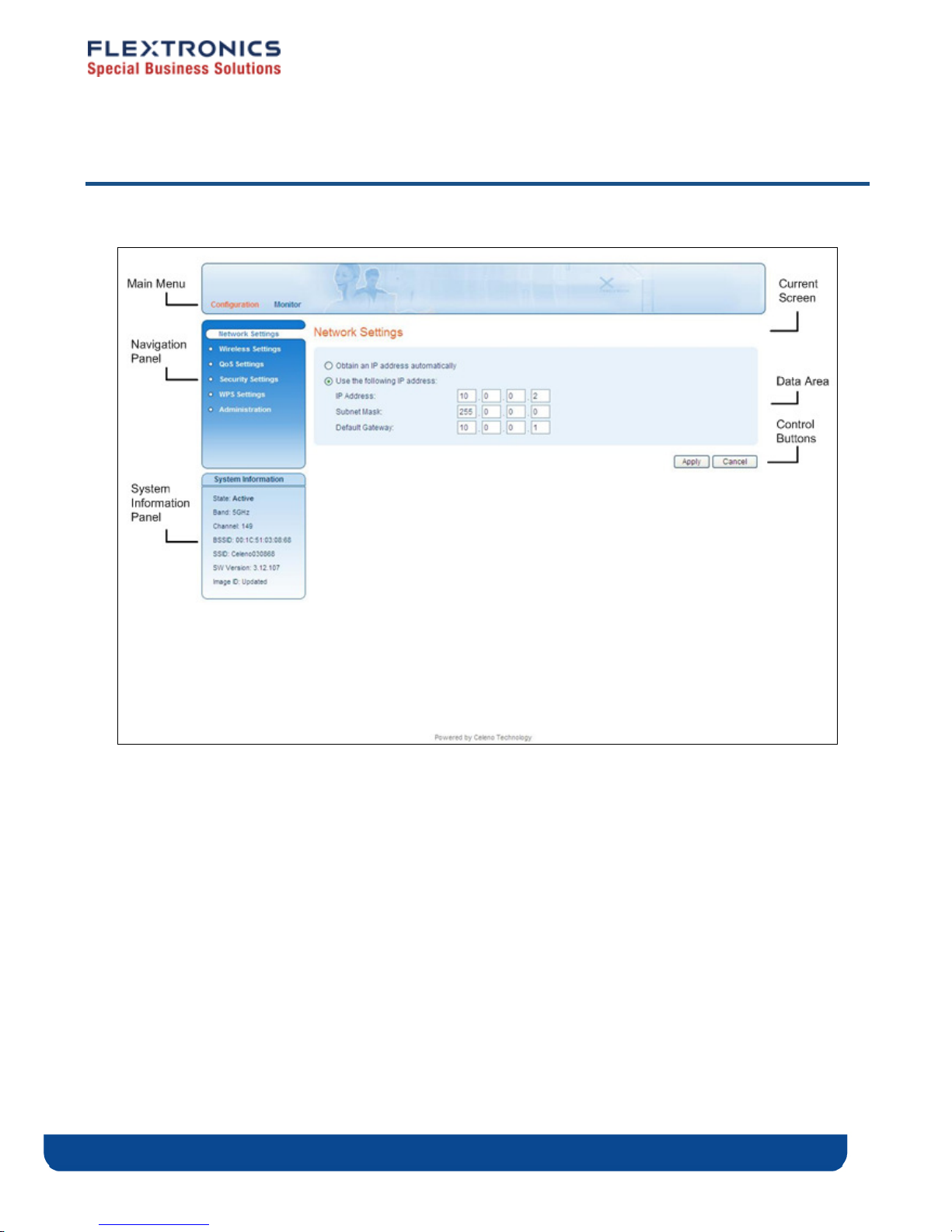
Navigating the MWB1305 Management Application
Figure 12: MWB1305 Management Application Window
The MWB1305 Management Application contains the following controls and areas to help
you navigate to all its parameters.
Main Menu – Enables you to access the functions of the MWB1305 Management
Application. The Main Menu is divided into the following submenu items:
Configuration and Monitor.
Navigation Panel – Displays the configuration screens available for each submenu item.
Current Screen – Displays the name of the current configuration screen.
Copyright © 2009 Flextronics Special Business Solutions | Design. Build. Ship. Service pg. 25
Page 26

System Information Panel – Displays system status information. This panel is always
visible and displays the following information:
State – Indicates whether the system is currently active or stopped.
Band – Indicates that the system is currently transmitting in the 5Ghz radio band.
Channel – The index number of the channel currently in use.
BSSID – Basic Service Set Identifier. The MWB1305 MAC address in an
infrastructure mode BSS. This field uniquely identifies each BSS. You cannot
configure this parameter using the MWB1305 Management Application.
SSID – Service Set Identifier. The code attached to beacon frames and connection
establishment frames.
SW Version – The current software image version of the device.
Image ID - Updated, the currently active software image is up to date. Factory, the
currently active software image is the factory default and should be updated.
Data Area – For each configuration screen, the Data Area displays the relevant
parameters and controls.
Control Buttons – Enable you to perform operations related to the current
configuration screen.
pg. 26 Copyright © 2009 Flextronics Special Business Solutions | Design. Build. Ship. Service
Page 27

Managing the MWB1305 Device
The MWB1305 Management Application is a user-friendly application that enables you to
configure and control all the parameters of the MWB1305. The main menu contains the
following options:
Configuration
Monitor
Note: Clicking Cancel in any of the MWB1305 Management Application windows discards any
unsaved changes you have made. The MWB1305 Management Application then re-queries
the MWB1305 device and refreshes the display.
4
Copyright © 2009 Flextronics Special Business Solutions | Design. Build. Ship. Service pg. 27
Page 28
Configuring the MWB1305 Device
Defining Network Settings
To define network settings:
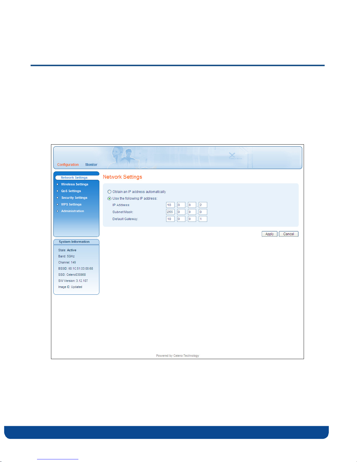
1. From the main menu of the MWB1305 Management Application, click Configuration.
The Configuration, Network Settings window appears.
Figure 13: MWB1305 Management Application – Configuration, Network Settings Window
pg. 28 Copyright © 2009 Flextronics Special Business Solutions | Design. Build. Ship. Service
Page 29

The following table describes the parameters you can configure from this window:
Table 5: MWB1305 Configuration – Network Parameters
Parameter Description
Obtain an IP address
automatically
Use the following IP
address
IP Address The IP address of the MWB1305 device.
Subnet Mask The subnet mask of the MWB1305 device.
Default Gateway The default gateway of the MWB1305 device.
When selected, the device IP address is obtained
automatically using DHCP.
When selected, the device IP address is set
manually.
2. Click Apply to update the settings immediately. The system displays an update
message.
3. Click Yes and wait several seconds for the system to restart.
Copyright © 2009 Flextronics Special Business Solutions | Design. Build. Ship. Service pg. 29
Page 30
Defining Wireless Settings
To define wireless settings:
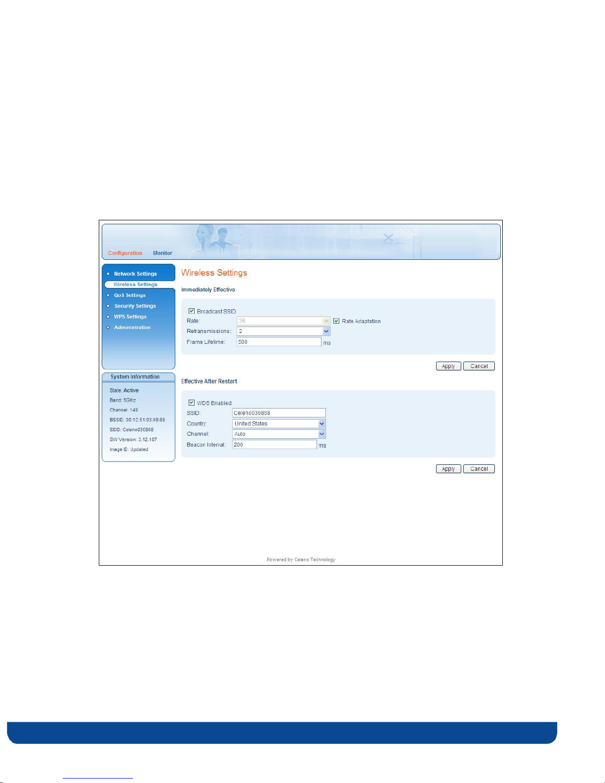
1. From the main menu of the MWB1305 Management Application, click Configuration
and from the Navigation Panel, click Wireless Settings. The Configuration, Wireless
Settings window appears.
Figure 14: MWB1305 Management Application – Configuration, Wireless Settings Window
The Wireless Settings window is divided into Immediately Effective settings that can be
updated while the device is running and Effective After Restart settings that are stored
and updated only after the MWB1305 device is restarted.
pg. 30 Copyright © 2009 Flextronics Special Business Solutions | Design. Build. Ship. Service
Page 31
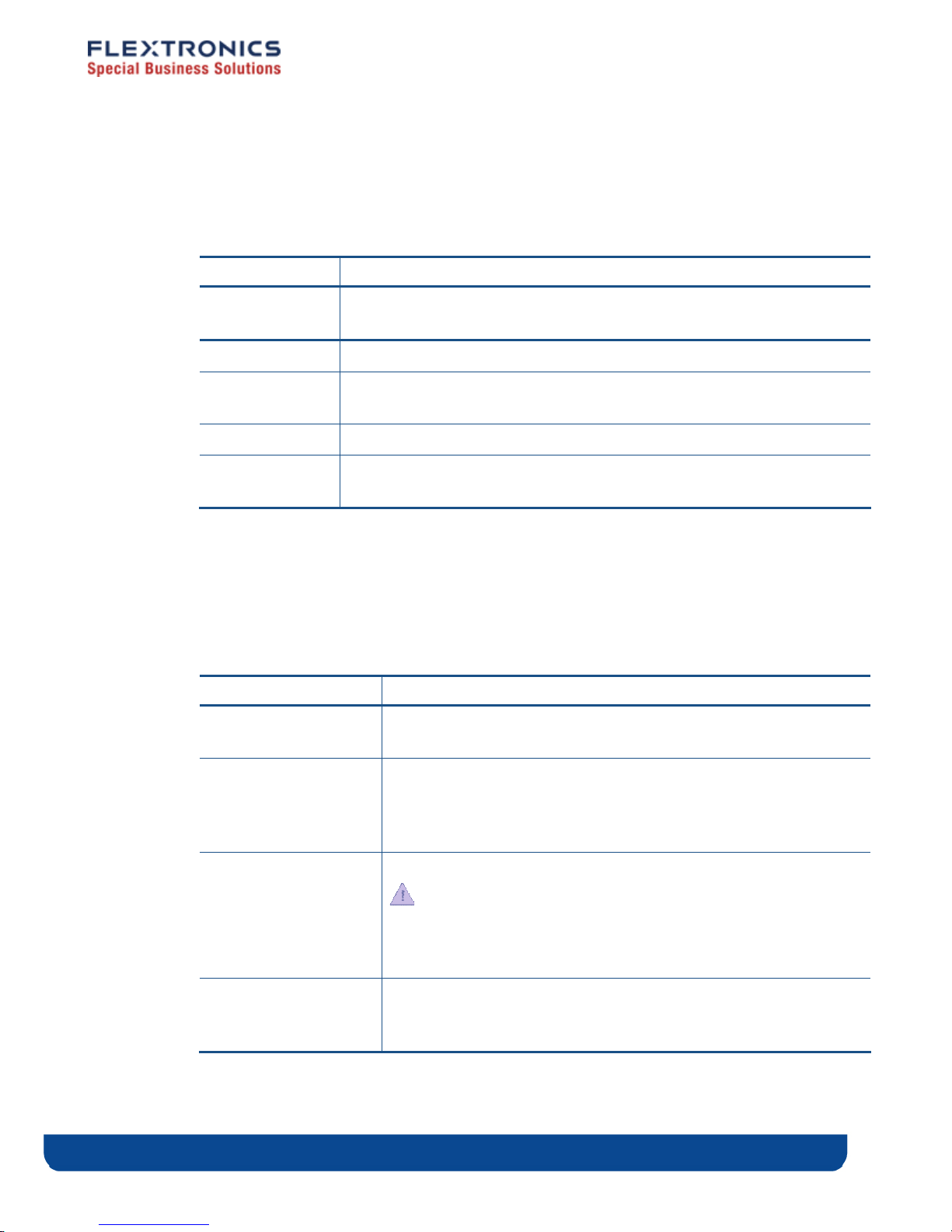
The following table describes the parameters you can configure in the Immediately
Effective area:
Table 6: MWB1305 Configuration – Immediately Effective Wireless Parameters
Parameter Description
Broadcast SSID When checked, the system broadcast its SSID in beacon and probe
response frames.
Rate The transmission rate. Possible values: 6, 9, 12, 18, 24, 36, 48, and 54 Mbps.
Rate Adaptation When checked, the system dynamically adapts the transmission rate to
suit current network conditions.
Retransmissions The number of retries in the case of transmission failure. Possible values: 0 – 6.
Frame Lifetime The maximum amount of time that a frame can be stored in the MWB1305
before it is discarded. Possible values: 10 – 500 milliseconds.
2. Click Apply to update the settings immediately. The system displays an update message.
3. Click OK to close the message and refresh the current window.
The following table describes the parameters you can configure in the Effective After
Restart area:
Table 7: MWB1305 Configuration – Effective after Restart Wireless Parameters
Parameter Description
WDS Enabled When checked, the system works as a Wireless Distribution System
thus providing a Transparent Bridge Functionality.
SSID Service set identifier. The code attached to beacon frames and
connection establishment frames. The SSID is a string of ASCII
characters. Entering an empty string restores the value of the SSID
field to factory default.
Country Your country of operation.
This device will automatically limit the allowable channels
determined by the current country of operation. Incorrectly entering
the country of operation may result in illegal operation and may
cause harmful interference to other systems.
Channel Select the desired channel from the dropdown list, or let the system
Copyright © 2009 Flextronics Special Business Solutions | Design. Build. Ship. Service pg. 31
select the best working channel automatically by choosing ‘Auto’
from the drop down list.
Page 32

Parameter Description
Beacon Interval The time interval between beacon frames sent out by the system.
Possible values: 100 – 1000 milliseconds in steps of 100 milliseconds.
4. Click Apply to update the settings. The system stores the new settings and prompts
you to restart the system.
5. Click YES and wait several seconds for the system to restart.
pg. 32 Copyright © 2009 Flextronics Special Business Solutions | Design. Build. Ship. Service
Page 33
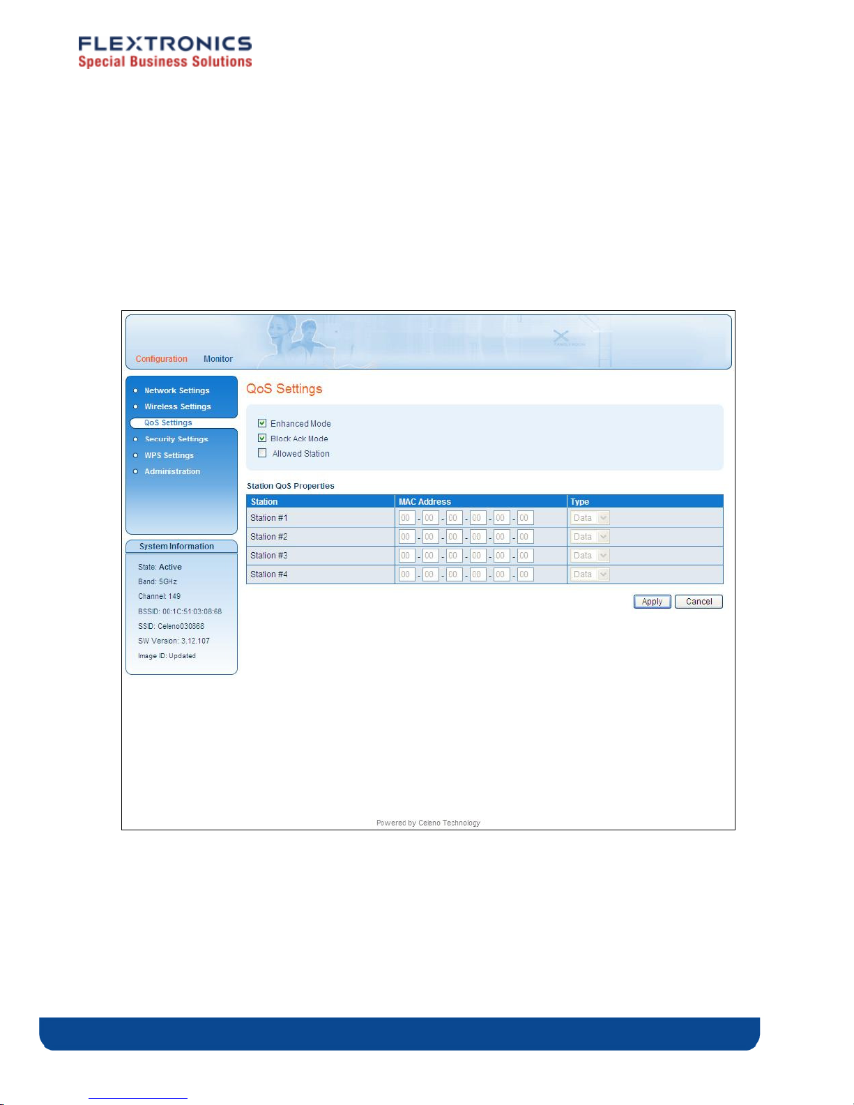
Defining QoS Settings
To define QoS settings:
1. From the main menu of the MWB1305 Management Application, click Configuration
and from the Navigation Panel, click QoS Settings. The Configuration, QoS Settings
window appears.
Figure 15: MWB1305 Management Application – Configuration, QoS Settings Window
Copyright © 2009 Flextronics Special Business Solutions | Design. Build. Ship. Service pg. 33
Page 34

The following table describes the parameters you can configure from this window:
Table 8: MWB1305 Configuration – QoS Parameters
Parameter Description
Enhanced Mode When checked, the system works in burst scheduling mode,
increasing system capacity. If cleared, the Block Ack Mode is
inactive and grayed out.
Block Ack Mode When checked, the system works in 802.11e Block Ack Mode,
further increasing system capacity.
Allowed Station When checked, only the MWS1000s listed in the Station QoS
Properties table are allowed to communicate with the
MWB1305. When cleared, any MWS1000 can communicate
with the MWB1305.
Station The number of the MWS1000 communicating with the
MWB1305.
MAC Address The MAC address of the MWS1000 communicating with the
MWB1305.
Type The type of data transported to the MWS1000. Possible values:
Data, Video.
Note: The new settings will take effect after restarting the system.
2. Click Apply to update the settings offline. The system stores the new settings and
prompts you to restart the system.
3. Click YES and wait several seconds for the system to restart.
pg. 34 Copyright © 2009 Flextronics Special Business Solutions | Design. Build. Ship. Service
Page 35

Defining Security Settings
To define Security settings:
From the main menu of the MWB1305 Management Application, click Configuration and
from the Navigation Panel, click Security Settings. The Configuration, Security Settings
window appears.
The MWB1305 device can be configured to operate in one of the following security modes:
Unsecured – Wireless security is disabled, any client can associate to the MWB1305
Access Point and the wireless signal is passed unencrypted.
WEP – Stands for Wired Equivalent Privacy. It is based on the IEEE 802.11 standard
and uses RC4 encryption algorithm. WEP provides moderate security to your system
and has been deprecated by WPA2.
WPA2 – Stands for WiFi Protected Access. It is based on the IEEE 802.11i standard and
uses AES encryption algorithm. WPA2 is much more secure then WEP, it provides
better encryption and user authentication which is generally missing in WEP. It is
recommended that you enable WPA2 at all times.
“To be able to use Wireless Protected Setup(WPS) features (See Defining WPS Settings at
page 39), it is required that you enable the WPA2 security mode ”.
Each security mode has its own configuration parameters, and the layout of the Security
Settings screen is changed according to the selection of the security mode:
Copyright © 2009 Flextronics Special Business Solutions | Design. Build. Ship. Service pg. 35
Page 36
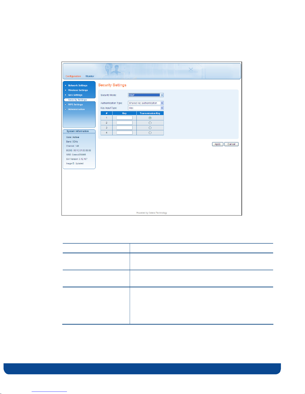
WEP mode
Figure 16 - MWB1305 Management Application – Configuration, Security Settings Window, WEP Mode
Table 9: MWB1305 Configuration – Security Parameters, WEP mode.
Parameter Description
Security Mode The selected security mode. Possible values: Unsecured, WEP
and WPA2.
Authentication Type The selected authentication type. Possible values: Open
authentication, Shared key authentication.
Key Input Type The WEP encryption keys can be input using either
Hexadecimal or Ascii characters. 10 character strings are
required when keys are input using Hexadecimal characters
and 5 character strings is required when keys are input using
Ascii characters.
pg. 36 Copyright © 2009 Flextronics Special Business Solutions | Design. Build. Ship. Service
Page 37

Parameter Description
Keys table It is possible to configure up to 4 different keys into the
MWB1305. The MWB1305 will be able to decipher incoming
transmissions that were encrypted using any of these keys.
Key A WEP encryption key.
Transmission key When selected, this key will be used by the MWB1305 for
encrypting its transmissions over the wireless medium.
Copyright © 2009 Flextronics Special Business Solutions | Design. Build. Ship. Service pg. 37
Page 38
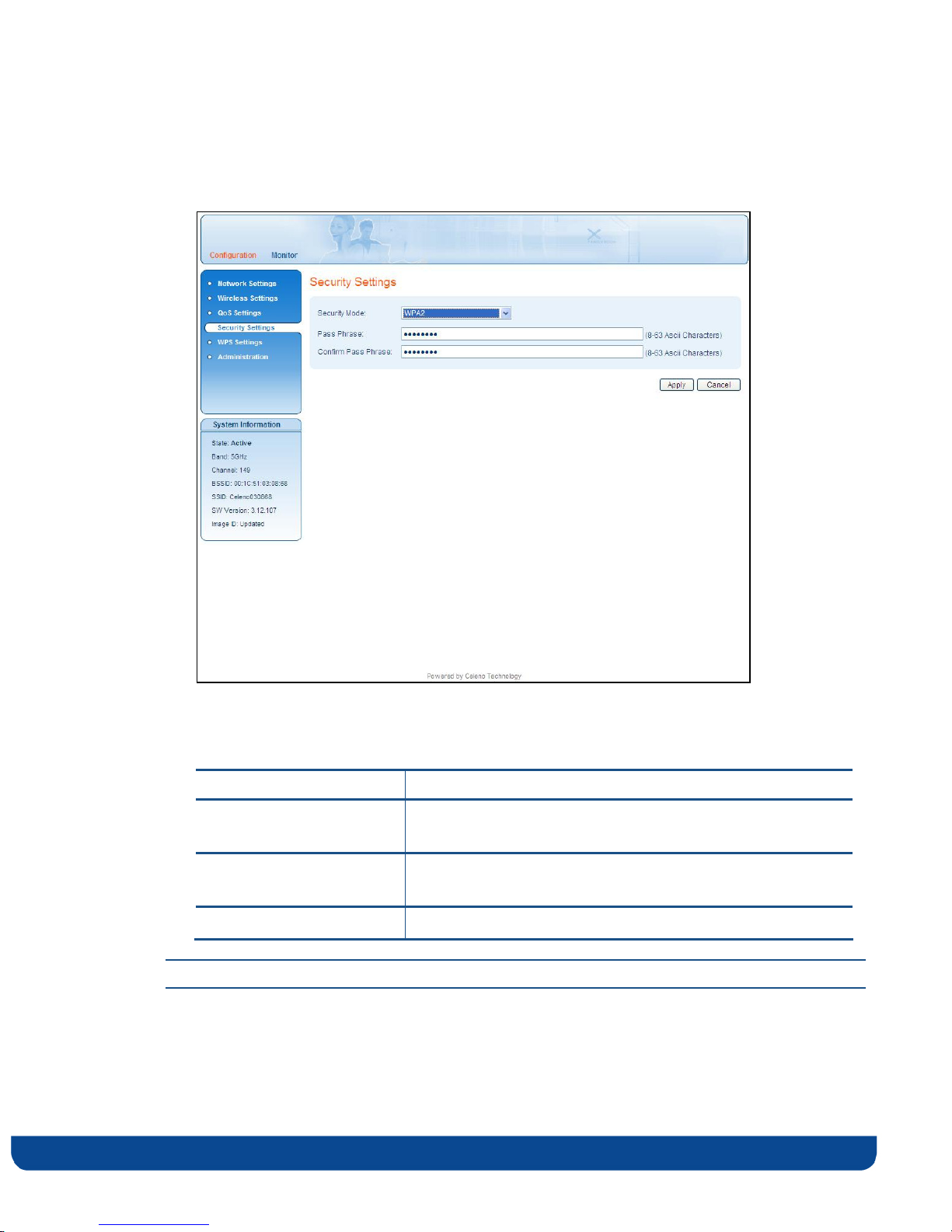
WPA2 mode
Figure 17 - MWB1305 Management Application – Configuration, Security Settings Window, WPA2 Mode
Table 10: MWB1305 Configuration – Security Parameters, WPA2 mode.
Parameter Description
Security Mode The selected security mode. Possible values: Unsecured, WEP
and WPA2.
Pass Phrase The security pass phrase to be used for generating the WPA2
encryption keys. The pass phrase can be 8 to 63 bytes long.
Confirm Pass Phrase Pass phrase confirmation.
Note: The new settings will take effect after restarting the system.
Click Apply to update the settings offline. The system stores the new settings and prompts
you to restart the system.
pg. 38 Copyright © 2009 Flextronics Special Business Solutions | Design. Build. Ship. Service
Page 39
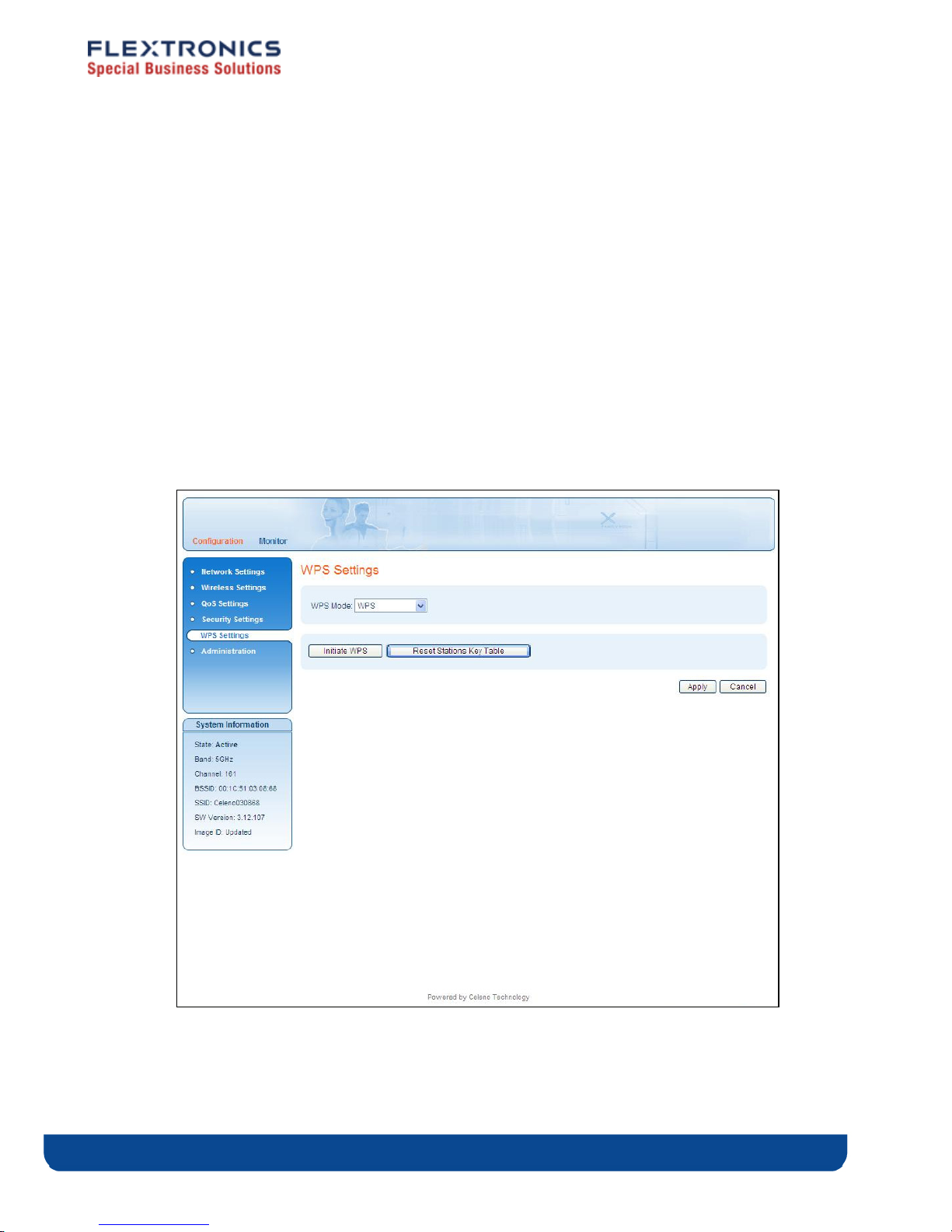
Defining WPS Settings
WPS is a standard for easy and secure setup of wireless home networks, created by the
WiFi allegiance. The MWB1300 Kit implements the WPS-PBC configuration method
allowing you to pair MWB1305 and MWS1000 devices using a push button (See Pairing
your Devices on page 17).
To define WPS settings:
1. From the main menu of the MWB1305 Management Application, click Configuration
and from the Navigation Panel, click WPS Settings. The Configuration, WPS Settings
window appears.
Figure 18: MWB1305 Management Application – Configuration, WPS Settings Window
Copyright © 2009 Flextronics Special Business Solutions | Design. Build. Ship. Service pg. 39
Page 40

The following table describes the actions that can be performed from this window:
Table 11: MWB1305 Configuration – WPS Parameters
Parameter Description
WPS Mode Enable / Disable WPS.
Initiate WPS Initiate a WPS pairing process. This has the same effect as
pushing the WPS button on the device.
Reset Stations Key Table Erases all previous pairings between MWS1000 Clients and
the MWB1305 Access Point.
Note: The new settings will take effect after restarting the system.
2. Click Apply to update the settings offline. The system stores the new settings and
prompts you to restart the system.
Click YES and wait several seconds for the system to restart.
pg. 40 Copyright © 2009 Flextronics Special Business Solutions | Design. Build. Ship. Service
Page 41
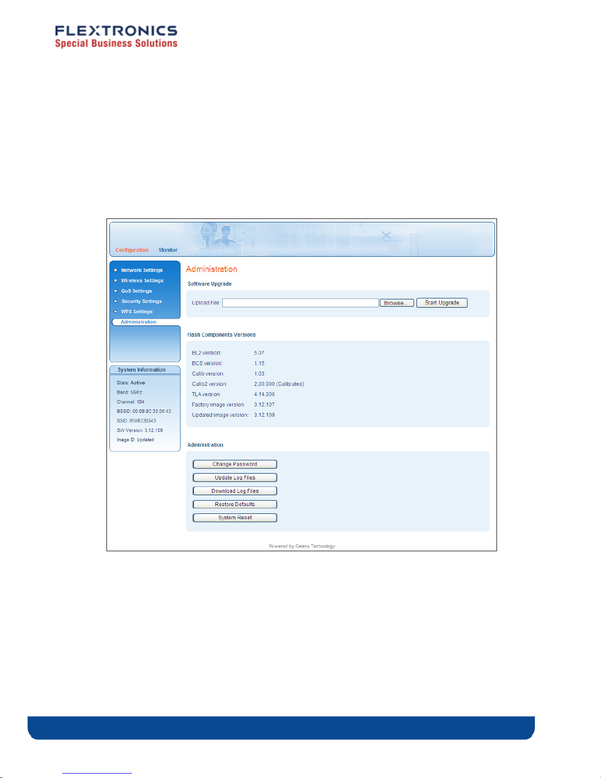
Performing Administration
To perform administration:
1. From the main menu of the MWB1305 Management Application, click Configuration
and from the Navigation Panel, click Administration. The Configuration,
Administration window appears.
Figure 19 - MWB1305 Management Application – Configuration, Administration Window
The Configuration, Administration window is divided into the following sections:
Software Upgrade
Flash Components
Control Buttons
Copyright © 2009 Flextronics Special Business Solutions | Design. Build. Ship. Service pg. 41
Page 42

To perform Software Upgrade:
1. Click the browse button, select the new image file and press Open.
2. Click the Start Upgrade Button, confirm the action by pressing OK in the confirmation
window and wait for the action to finish.
3. After the Software Upgrade finishes you can see the new software version number in
the System Information Panel.
“Do not power off or reset the MWB1305 device while Software Upgrade is in progress”.
pg. 42 Copyright © 2009 Flextronics Special Business Solutions | Design. Build. Ship. Service
Page 43
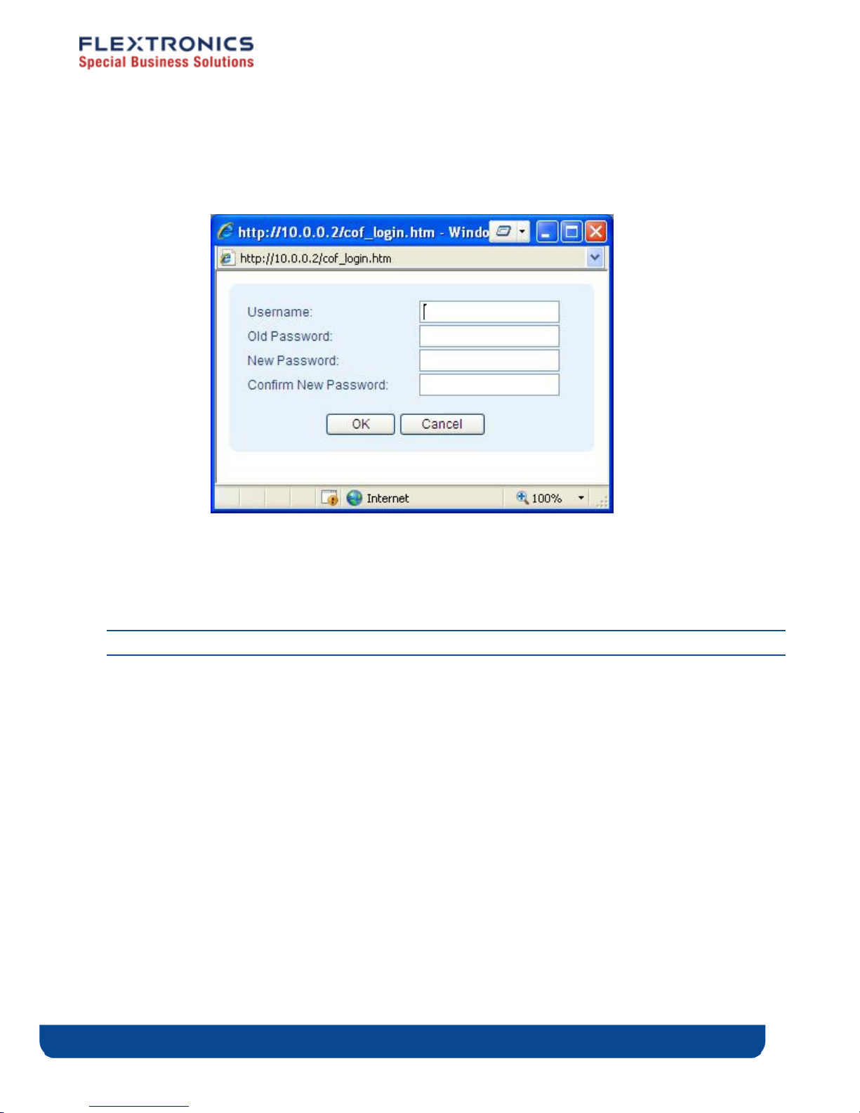
To change the password of the MWB1305:
1. Click the Change Password Button. The following window appears:
Figure 20 - MWB1305 Management Application – Change Password Window
2. Fill the new password details in the change password window and press OK.
3. After the successful completion of the operation you will be prompted to login again.
Note: Only a single user (admin) is supported in the current release.
To update log files on the MWB1305 device:
1. Click the Update Log Files Button.
2. Wait for the update process to complete.
To download log files from the MWB1305 device:
1. Click the Download Log Files Button.
2. A confirmation window will prompt you to confirm the download of each log file in
the system.
Copyright © 2009 Flextronics Special Business Solutions | Design. Build. Ship. Service pg. 43
Page 44

To restore the MWB1305 configuration to factory defaults:
1. Click the Restore Defaults Button, confirm the action by pressing OK in the confirmation
window and wait for the action to finish.
To reset the MWB1305 device:
1. Click the Reset Button, confirm the action by pressing OK in the confirmation window
and wait for the action to finish.
The values under Flash Components Versions provide detailed information about the internal
revisions of various components on the MWB1305 flash.
pg. 44 Copyright © 2009 Flextronics Special Business Solutions | Design. Build. Ship. Service
Page 45
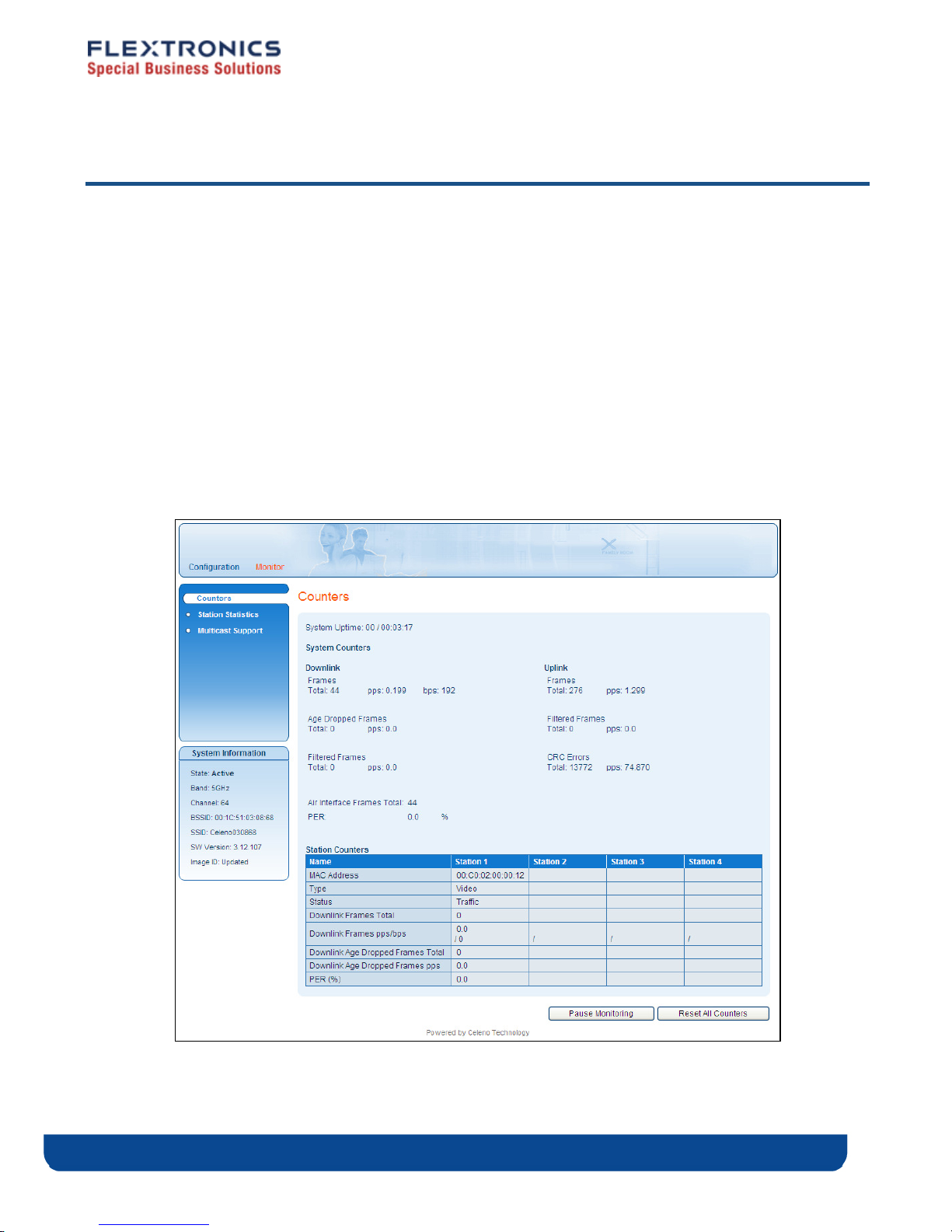
Monitoring the MWB1305 Device
The MWB1305 Management Application Monitor displays information about the current
status of your MWB1305 Device. The system continually monitors a variety of network
parameters and displays them in the Counters, Station Statistics and Multicast Support
windows.
Viewing System and Station Parameters
To view System and Station Parameters:
From the main menu of the MWB1305 Management Application, click Monitor. The
Monitor, Counters window appears.
Figure 21: MWB1305 Management Application – Monitor, Counters Window
Copyright © 2009 Flextronics Special Business Solutions | Design. Build. Ship. Service pg. 45
Page 46

The Monitor, Counters window is divided into the following sections:
System Counters, Downlink
System Counters, Uplink
Station Counters
Control Buttons
The following table describes the Monitor, Counters Window:
Table 12: MWB1305 Configuration – Counters Parameters
Parameter Description
System Counters, Downlink
Frames Total – The total number of frames transmitted.
pps – Packets per second transmitted.
bps – Bits per second transmitted.
Age Dropped Frames Total – The total number of frames dropped because of lifetime expiration.
pps – Packets per second dropped because of lifetime expiration.
Filtered Frames Total – The total number of frames dropped because the destination was not
an associated MWS1000.
pps – Packets per second dropped because the destination was not an
associated MWS1000.
Air Interface Total The total number of frames transmitted over the air.
PER The percentage of failed frame transmissions.
System Counters, Uplink
Frames Total – The total number of frames received.
pps – Packets per second received.
Filtered Frames
CRC Errors
Station Counters
MAC Address The MWS1000 MAC Address.
Total – The total number of frames dropped because the source was not an
associated MWS1000.
pps – Packets per second dropped because the source was not an associated
MWS1000.
Total – The total number of received frames with bad CRC .
pps – Packets per second received with bad CRC.
Type The MWS1000 type – Possible values: Data or VIDEO.
Status
pg. 46 Copyright © 2009 Flextronics Special Business Solutions | Design. Build. Ship. Service
The MWS1000 status – Possible values: Associated, Disassociated,
Authenticated, Disauthenticated.
Page 47
Parameter Description
Downlink Frames Total The total number of frames transmitted to the MWS1000.
Downlink Frames pps/bps
Downlink Age Dropped
Frames Total
Downlink Age Dropped
Frames pps
PER (%)
The Monitor, Parameters window also provides controls to reset the parameter counters
and logs.
To reset the monitor parameter counters:
Click .
To pause monitoring:
Click . The Resume Monitoring button is displayed.
To resume monitoring:
pps – Packets per second transmitted to the MWS1000.
bps – Bits per second transmitted to the MWS1000.
The total number of frames dropped because of lifetime expiration.
Packets per second dropped because of lifetime expiration.
The percentage of failed frame transmissions to MWS1000.
Click . The Pause Monitoring button is displayed.
Copyright © 2009 Flextronics Special Business Solutions | Design. Build. Ship. Service pg. 47
Page 48
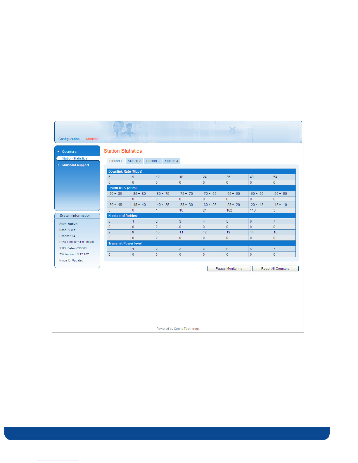
Viewing Station Statistics
1. From the main menu of the MWB1305 Management Application, click Monitor and
from the Navigation Panel, click Station Statistics. The Station Statistics window
appears.
Figure 22: MWB1305 Management Application – Monitor, Station Statistics Window
pg. 48 Copyright © 2009 Flextronics Special Business Solutions | Design. Build. Ship. Service
Page 49
The following table describes the Monitor, Station Statistics Window:
Table 13: MWB1305 Configuration – Station Statistics Parameters
Parameter Description
Downlink Rate (Mbps) The number of packets transmitted (to a specific MWS1000) at
a specified data rate.
Uplink RSSI (dBm) The number of packets received from the client at a specified
range of received signal levels.
Number of Retries The number of retransmissions to a specific client.
Transmit Power Level The number of packets transmitted to the client at a specified
transmission power level.
2. Click the various station tabs to view information for the different MWS1000s.
Copyright © 2009 Flextronics Special Business Solutions | Design. Build. Ship. Service pg. 49
Page 50
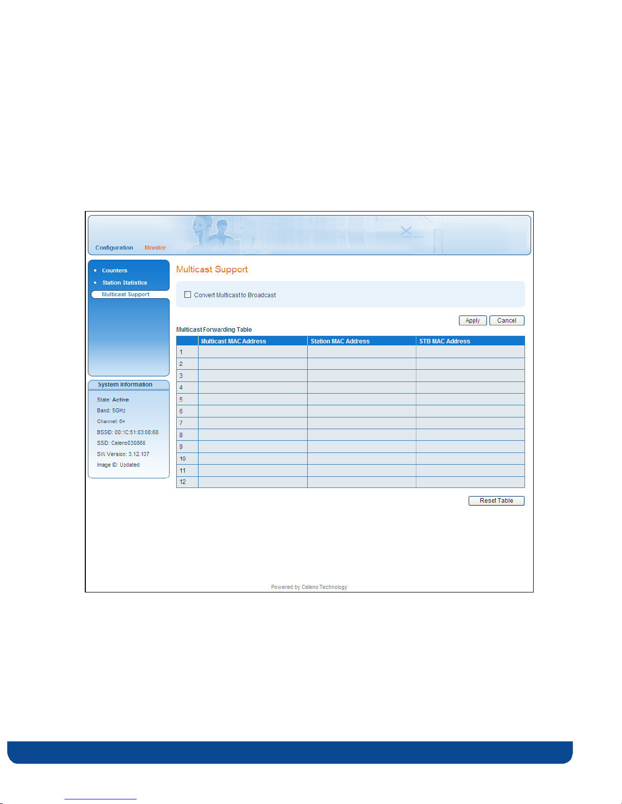
Viewing Multicast Status
1. From the main menu of the MWB1305 Management Application, click Monitor and
from the Navigation Panel, click Multicast Support. The Multicast Support window
appears.
Figure 23: MWB1305 Management Application – Monitor, Multicast Support Window
pg. 50 Copyright © 2009 Flextronics Special Business Solutions | Design. Build. Ship. Service
Page 51

The following table describes the Monitor, Multicast Support Window:
Table 14: MWB1305 Configuration – Station Statistics Parameters
Parameter Description
Convert Multicast to
Broadcast
Multicast MAC Address The MAC address of the Multicast video stream.
Station MAC Address The MAC address of the Station that receives the Multicast
STB MAC Address The MAC address of the Set Top Box that receives the
When checked, unmapped Multicast streams are converted to
broadcast.
When cleared, unmapped Multicast streams are dropped.
stream.
Multicast stream.
Copyright © 2009 Flextronics Special Business Solutions | Design. Build. Ship. Service pg. 51
Page 52

Page 53
Updating the MWS1000
This appendix describes how to upload a new firmware version into the MWS1000 device.
To upload a new firmware version into the MWS1000 device
1. Connect a Category 5 (CAT5) Ethernet cable from the Ethernet port of the MWS1000 to
your computer.
2. Power up the MWS1000 device.
3. Configure your computer to be on the same subnet as the MWS1000 (refer to Changing
Your Computer’s IP Address on page 21). Since this disconnects your computer from
your computer network, you may need to restore this setting later.
A
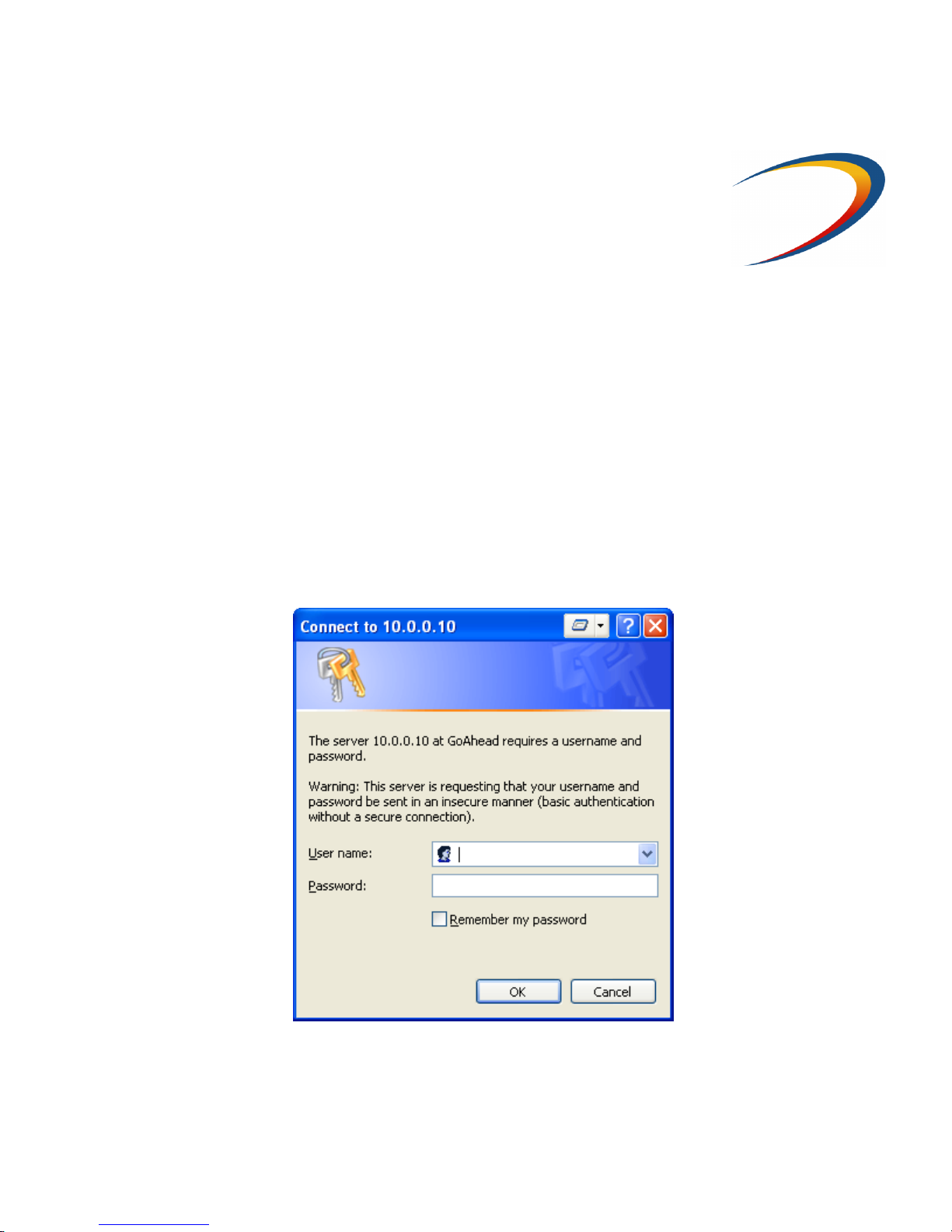
4. Open a WEB browser and enter the MWS1000 Client’s address: 10.0.0.10
5. The following user/password screen appears:
Enter admin as the user space and admin as the password and press OK.
Design. Build. Ship. Service
Page 54
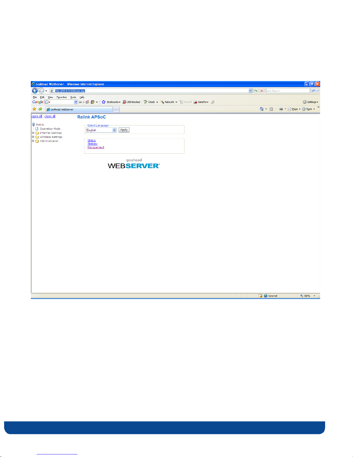
6. The following screen appears:
Open the Administration folder on the left side of the screen and select the Upload firmware item.
pg. 54 Copyright © 2009 Flextronics Special Business Solutions | Design. Build. Ship. Service
Page 55
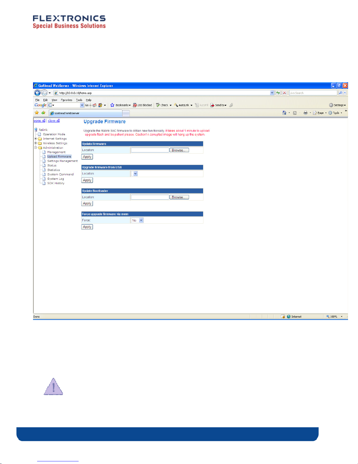
7. The following screen appears
8. Click the browse button in the Update Firmware section and select the new image file and
press Open.
9. Click the Apply Button, and wait for the action to finish.
10. You can view the new firmware version number by opening the Wireless Settings folder
on the left side of the screen and selecting the about item.
“Do not power off or reset the MWS1000 device while Software Upgrade is in progress”.
Copyright © 2009 Flextronics Special Business Solutions | Design. Build. Ship. Service pg. 55
Page 56

B
Troubleshooting MWB1300 Kit
Basic setup
Symptom Advised solution
Make sure that:
The power cord is connected to the device and that
the power adapter is properly connected to a
The Power LED is not on
functioning power outlet.
You are using the power adapter that was supplied
with the product.
The LAN LED is not on
The WLAN LED is not on
After completing a pairing
process the link quality LED
flashes yellow
The Link quality LED is not
on or is yellow and you are
seeing artifacts on the TV
screen
Make sure that:
The LAN cable connectors are securely plugged in at
the wireless video extender device and at the
network device (gateway, modem or set top box).
The connected network device is turned on.
You are using the correct cable type for your
Ethernet equipment that is at least UTP CAT5 with
RJ45 connectors.
Make sure that you have completed a successful
pairing procedure as described in Pairing your
Devices on page 17 herein.
Make sure that you are not attempting to pair more
then one MWS1000 device at the same time.
Make sure that the wireless video extender devices
are placed according to the recommendation in
Placing and connecting your devices on page 18
herein.
The LAN, WLAN LEDs are
flashing green and the link
pg. 56 Copyright © 2009 Flextronics Special Business Solutions | Design. Build. Ship. Service
The device is experiencing a severe malfunction.
Page 57
quality LED is flashing
yellow at the same time
No access to the MWB1305
web control pages.
Please contact your service provider or local dealer.
Make sure that your computer IP address is
10.XXX.YYY.ZZZ and its subnet mask is 255.0.0.0.
For further information refer to Changing Your
Computer’s IP Address in the page 21 herein.
If your MWB1305 IP address has been changed,
please assign the computer an IP address in the
same range as the MWB1305 IP Address.
Remember: Whenever a change is made in the Setup of the
Access Point, the Apply button must be used to save the
settings to the Access Point.
Remember: The Access Point control web page is not
accessible from the wireless client/adapter segment.
Copyright © 2009 Flextronics Special Business Solutions | Design. Build. Ship. Service pg. 57
Page 58

C
Technical Specifications
MWB 1300 Physical Characteristics
Power
requirements
Physical size
Weight
Antennas
Ethernet ports
Environmental
conditions
MWB1305 - 12Vdc, Powered from external certified AC/DC adaptor.
MWS1000 – 5Vdc, Powered from external certified AC/DC adaptor.
MWB1305 - 153mm(L) x 41mm(W) x 178mm(H)
MWS1000 – 109mm(L) x 37mm(W) x 155mm(H)
MWB1305 – 450gr
MWS1000 – 300gr
MWB1305 – 4 internal printed antennas
MWS1000 – 2 internal printed antennas
1 auto MDX, RJ45 port
Temperature:
Operation: 0 - 40°C
Storage: -20 - 60°C
Humidity:
Operation: 0 – 95%
Storage: 0 – 95%
pg. 58 Copyright © 2009 Flextronics Special Business Solutions | Design. Build. Ship. Service
Page 59

Regulatory Compliance Information
Europe – EU Declaration of Conformity
This device complies with the essential requirements of the R&TTE Directive 1999/5/EC.
The following test methods have been applied in order to prove presumption of
compliance with the R&TTE Directive 1999/5/EC:
D
Safety - EN60950-1:2006.
EMC - EN301 489-1 V1.8.1:2008-04, EN301 489-17 V1.3.2:2008-04.
RF – EN301 893 V1.4.1:2007-07
FCC Requirements for Operation in the United States
Federal Communication Commission Statement
This equipment has been tested and found to comply with the limits for a Class B digital
device, pursuant to Part 15 of the FCC Rules. These limits are designed to provide
reasonable protection against harmful interference in a residential installation. This
equipment generates, uses and can radiate radio frequency energy and, if not installed and
used in accordance with the instructions, may cause harmful interference to radio
communications. However, there is no guarantee that interference will not occur in a
particular installation. If this equipment does cause harmful interference to radio or
television reception, which can be determined by turning the equipment off and on, the
user is encouraged to try to correct the interference by one of the following measures:
Reorient or relocate the receiving antenna.
Increase the separation between the equipment and receiver.
Copyright © 2009 Flextronics Special Business Solutions | Design. Build. Ship. Service pg. 59
Page 60

Connect the equipment into an outlet on a circuit different from that to which the
receiver
is connected.
Consult the dealer or an experienced radio/TV technician for help.
FCC Warning
Changes or modifications not expressly approved by the party responsible for compliance
could void the user’s authority to operate the equipment.
FCC RF Radiation Exposure Statement
This equipment complies with FCC radiation exposure limits set forth for uncontrolled
equipment and meets the FCC radio frequency (RF) Exposure Guidelines in Supplement C
to OET65. This equipment should be installed and operated with at least 20cm and more
between the radiator and person’s body (excluding extremities: hands, wrists, feet and
legs). This transmitter must not be co-located or operating in conjunction with any other
antenna or transmitter.
Industry Canada (IC) Statement
The wireless radio of this device complies with RSS 139 & RSS 210 Industry Canada. This
Class B digital apparatus complies with Canadian ICES-003.
Operation is subject to the following two conditions: (1) this device may not cause
interference, and (2) this device must accept any interference, including interference that
may cause undesired operation of the device.
Cet appareil numérique de la classe B conforme á la norme NMB-003 du Canada.
pg. 60 Copyright © 2009 Flextronics Special Business Solutions | Design. Build. Ship. Service
 Loading...