

Page 1
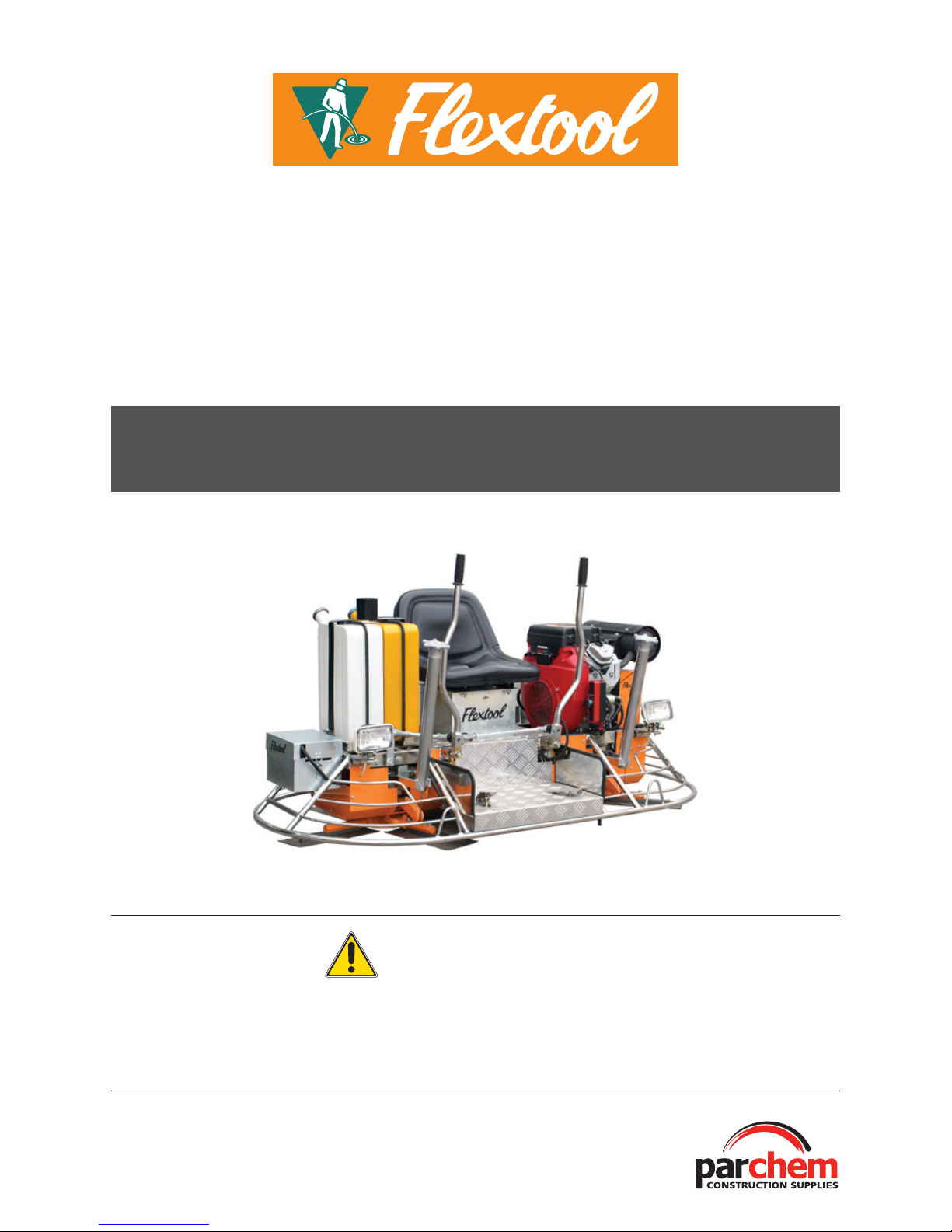
FLEXTOOL RIDE ON TROWEL
FP836
WARNING
To reduce the risk of injury, all operators and maintenance personnel must read and understand
these instructions before operating, changing accessories, or performing maintenance on this power
equipment. All possible situations cannot be covered in these instructions. However care must be
exercised by everyone using, maintaining or working near this equipment.
O P E R A T I N G I N S T R U C T I O N S
Page 2
2
CONTENTS
Introduction 2
Applications 2
Function and Controls 2
Hazards & Risks 3
Operation 4
Customer Responcibility 5
Care and Preventive Maintenance 6
Troubleshooting 6
Specifications 7
Spare Parts and Service 8
INTRODUCTION
Thank you for your selection of Parchem equipment.
Parchem have specialised in the design and manufacture of quality
products since 1951.
We have taken care in the assembly and testing of this product.
Should service or spare parts be required, prompt and efficient
service is available from our branches.
General Safety Instructions for the Operation of Power Equipment
The goal of Parchem is to produce power equipment that helps
the operator work safely and efficiently. The most important safety
device for this or any tool is the operator.
Care and good judgement are the best protection against injury.
All possible hazards cannot be covered here, but we have tried
to highlight some of the important ones. Individuals should look
for and obey Caution, Warning and Danger signs placed on
equipment, and displayed in the workplace. Operators should read
and follow safety instructions packed with each product.
Learn how each machine works. Even if you have previously used
similar machines, carefully check out each machine before you use
it. Get the “feel” of it and know its capabilities, limitations, potential
hazards, how it operates, and how it stops.
APPLICATIONS
The Ride On Power Trowel can be used for trowelling concrete
surface through floating and finishing operations. Three types of
blades can be fitted with the trowel: combination, floating and
finishing blades. Two types of float pans are compatible and
available: regular dish pan and mild dish pan.
FUNCTIONS AND CONTROLS
The trowel machine reproduces the action of hand trowels while
giving a high quality dense finish with wear resistance. The angle of
the blades is adjustable during operation from a floating position,
with the full blade area in contact to flatten the surface, to a
finishing position with the blades tilted to give a finished surface.
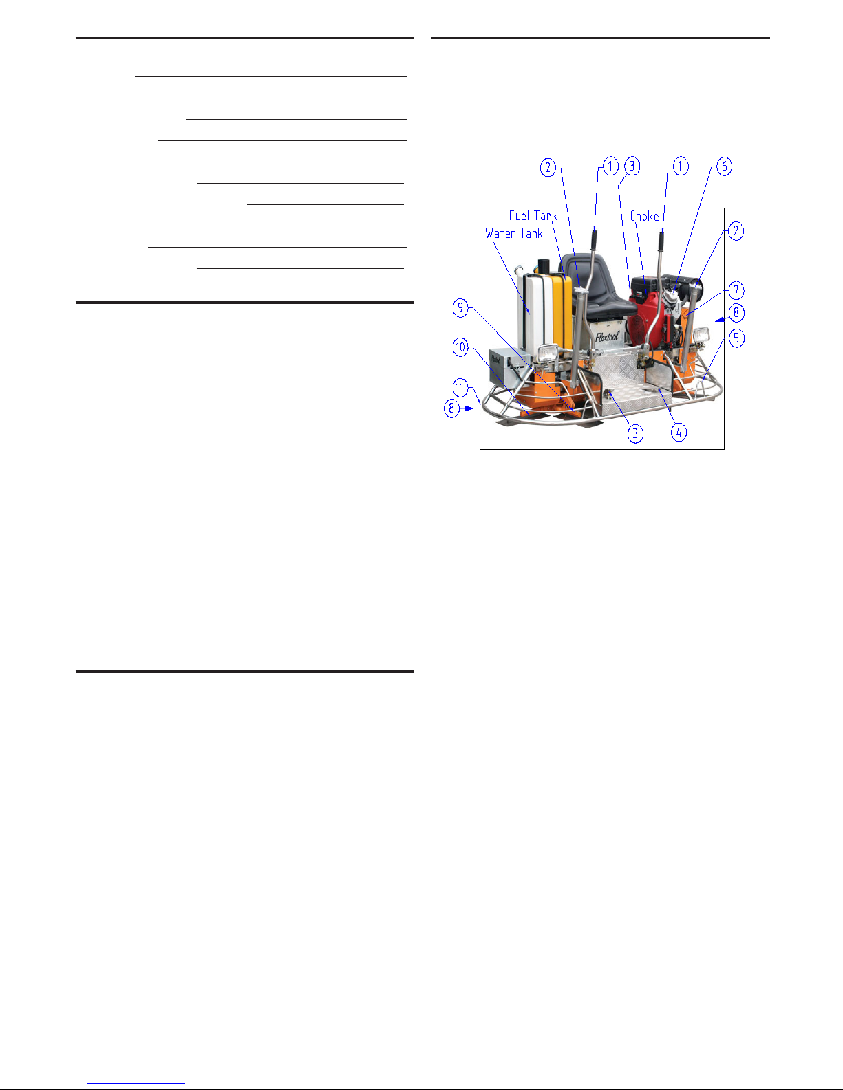
The figure above shows the location of the controls and
components for this Ride on Power Trowel. The functions of
controls are described below:
1. Handle Grip/Handle Bar – When operating the trowel, hold
both handgrips with hands. Replace handgrips when they are
worn or damaged.
2. Blade Pitch Control – Turn the star knob clockwise to
increase blade pitch, and counter-clockwise to decrease blade
pitch.
3. Throttle Control Lever – Controls the speed of engine. Push
the lever downwards to increase engine speed, upwards to
decrease engine speed.
4. Safety Stop Switch or Inertia Lever – If the operator loses
control and lets go of the trowel, the inertia lever will be swung
to OFF position by centrifugal force, and shut down the engine
or if a dead mans pedal is fitted releasing the foot pressure,
will stop the machine. These switches MUST be tested before
each use of the trowel. It is also recommended that these
switches be used to stop the engine after each use of the
trowel to validate there operation.
5. Lifting Frame – Use the lifting frame to lift the trowel and
move to desired location.
6. Engine – Honda V-Twin, 27HP Petrol engine.
7. V-belt Cover – Safety guard for V-belts and pulleys. Remove
the cover only to get access to the V-belts for inspection and
replacement. Make sure the cover is always in place when
trowel is in operation or de isolated.
8. Gearbox – Transfers power from engine to the spider
assembly. Check oil level in gearbox through the sight glass
on a daily basis, and refill as necessary only with machine
stopped.
9. Trowel Arm – NEVER use broken or bent trowel arms. Check
for arm alignment if blades show uneven wear or some wear
earlier than others only when machine stopped and isolated.
Page 3

3
10. Blades – Combination blades, floating blades and finishing
blades can be fitted with the trowel.
11. Guard Ring – NEVER attempt to put hands or feet inside the
guard ring while the engine is running.
HAZARDS AND RISKS
NEVER allow any person to operate machines without adequate
instruction, and a signed JSEA and Work Method Statement
provided.
ENSURE all operators read, understand and follow the operating
instructions.
SERIOUS INJURY may result from improper or careless use of this
machine.
Ride on Power trowels are heavy units and require mechanical lifting
device/ crane or a multiple person lift, using correctly trained lifting
techniques and people of appropriate strength. Where provided,
use the lifting eye for mechanical lifts using approved lifting devices.
! MECHANICAL HAZARDS
DO NOT operate the machine unless all protective guards are in
place. Ensure all warning labels are still visible.
ENSURE that the motor operation switch is in the OFF position
and the spark plug ignition lead is disconnected and drive belt
or coupling removed before removing the guards or making
adjustments.
DO NOT increase the governed no-load motor speed above 140
RPM. Any increase may result in personal injury and damage to the
machine.
Be sure the runaway protection dead mans switch provided is
working properly, not fixed in on position so that if the foot should
slip away from your control, the ignition supply will be cut off. While
operating machine, if control is lost by the operator, remove foot
from runaway protection dead mans switch.
Take care not to come in contact with the muffler or engine when
the engine is hot, since it may result in severe burns. Wear suitable
protective gloves
Keep hands and feet clear of rotating or moving parts as they will
cause injury if contact is made. DO NOT place fingers, hands or
feet with in the Ring Guard while machine is still running.
It is important that the operator is seated and balanced when
starting the engine ensuring the area is clear of persons.
When starting the trowel, do not exceed the ¼ throttle setting. A
higher setting could engage the centrifugal clutch.
Be careful with the trowel around pipes or cables sticking out of the
floor or other obstacles on the floor. Should the trowel blades catch
on these, serious damage to the machine or harm to the operator
may result.
ENSURE that repairs to the motor and machine are carried out only
by QUALIFIED personnel.
! FIRE & EXPLOSION HAZARDS
PETROL or diesel is extremely flammable and explosive under
some conditions.
ENSURE that petrol and diesel is only stored in an approved and
labelled storage container away from any source of ignition.
DO NOT refuel the motor while it is in running.
DO NOT refuel the motor in a confined space or in the vicinity
of ignition sources such as sparks, naked flames or a person
smoking.
DO NOT overfill the fuel tank and avoid spilling petrol or diesel when
refuelling. Spilled petrol and diesel or petrol vapour may ignite. If
spillage occurs, ensure that the machine is dry before starting the
motor.
ENSURE that the fuel tank cap is securely fitted after refuelling.
ENSURE a serviceable appropriate type and size fire extinguisher is
readily available for immediate use
! CHEMICAL HAZARDS
DO NOT operate or refuel a petrol or diesel motor in a confined
space without adequate ventilation.
CARBON MONOXIDE exhaust gases from internal combustion
motor driven units can cause death in confined spaces. Ensure
chemical TLV and oxygen content of area is safe for operation
WATER DISPENSER Careful not to get water on one self from end
of dispenser, located at the front of Trowel Machine.
! NOISE HAZARDS
EXCESSIVE NOISE can lead to temporary or permanent loss of
hearing.
WEAR an approved hearing protection device to limit noise
exposure, as required by Occupational Health and Safety
regulations.
! VIBRATION HAZARD
Excessive exposure to prolonged or extreme whole body and hand
vibration, can cause permanent injury
Ensure any abnormal or excessive vibration in equipment is
reported
Grip controls as lightly as possible within the bounds of safety using
vibration absorbing gloves
PROTECTIVE CLOTHING
WEAR protective goggles, long sleeve close fitted clothing, trousers
and safety footwear, gloves while operating the machine.
WEAR sun cream, sun goggles and wide brimmed hat in sunny
exposed or high light reflecting areas.
! ADDITIONAL HAZARDS
Slips/ trips/ falls are major causes of serious injury or death. Beware
of obstacles or water left on the walking or work surface.
Exercise caution and ensure that the perimeter of all elevated
formwork or platforms is protected per Australian Standards.
Ensure work platform or form work is adequate to support
concrete, equipment and persons applied load while wet
Always maintain good footing when stepping on to the Ride on
Trowel so that you do not slip
Ensure other persons and children are controlled and clear of the
area. Barricade as required
Ensure there are no electrical leads or hoses on floor being
trowelled
Page 4

4
OPERATION
BEFORE OPERATION
The following items should be checked on a daily basis before
operating the trowel.
• Engine oil level
• Gearbox oil level
• Blade condition and pitch control operation
• V-belt clutch operation
• The following items SHALL be checked on a daily basis before
operating the trowel.
• Safety Stop Switch operation. If the dead mans foot
pedal cut out switch is not fully functional to stop the
equipment in an emergency then the equipment SHALL be
tagged out DO NOT USE.
• Check warning labels in place and understood
STARTING THE ENGINE
1. Move the engine Fuel Valve Lever to “ON” position.
2. Move the Throttle Control Lever to “MIN” position.
3. Move the Safety Stop Switch to “ON” position or hold dead
mans Penal down with foot.
4. Place the Choke Lever in the “CLOSED” position.[ Petrol Only}
5. Rotate the Ignition key to Start the Engine – Electric start
feature.
6. If the engine has started, return the Choke Lever to “OPEN”
position; If the engine has not started, repeat 1 to 5 steps
above.
7. Run the engine for a few minute and make sure the machine
is in normal working condition.
8. Test the Safety Stop Switch or ‘dead mans pedal’. This test
should be conducted in a clear area. Remove left foot from
the ‘dead mans pedal’, with the engine at idle. The engine
should shut down. Move the switch to “ON” position or hold
‘dead mans pedal’, start the engine and let idle, swing the
trowel handle to the right and let go. The Safety Stop Switch
Lever where fitted should be swung to the “OFF” position to
shut down the engine.
9. DO NOT TAPE UP, TAMPER WITH OR DISABLE THESE
SAFETY DEVICES
10. To start trowelling, push the Foot Throttle Control Lever down
towards “MAX” position. Or press Right side pedal for throttle
control.
MACHINE OPERATION
Steering the machine on a slab is relatively simple but does require
some practice prior to actually working with the machine.
The illustration shows the necessary hand movements required to
move the trowel in the desired direction.
For straight line movements (forward and reverse) move the
handles in the same direction you wish to travel.
Move the handles in the opposite directions to produce rotation on
the machine axis.
Left handle forward, right handle backwards for clockwise
direction.
Left handle backwards, right handle forward for the counter
clockwise direction.
Sideways directionis achieved by moving the right handle either the
left or right direction.
To familiarize a new operator with the ride-on trowel the following
steps should be taken: With the operator seated on the machine
prior to starting the unit show them the function of the ignition
switch, deadman lever, throttle control, steering handles and blade
tilt levers. Prior to starting the unit, ensure the operator knows
the emergency stop procedure. To stop the unit the operator can
either release pressure from the deadman lever or release the
throttle control.
Once the operator is familiar with these controls they need to
practice steering the trowel. The best place for this is on a large
section of finished concrete which is at ground level.
With the blades in the flat position have the operator depress the
deadman lever and start the unit without depressing the throttle
control. With both hands on the steering handles the operator
should depress the throttle control to about half way and obtain
a feeling for the steering by making the machine hover in the one
spot.
Once the operator feels confident and is able to make small
steering inputs to maintain the position of the unit they may then
practice riding the machine in a straight line and making 180
degree turns. This is best done at full throttle as the machine is
easiest to control at full RPM.
The operator should continue to practice operating the unit until
they are familiar with the steering and operation of the unit. The
operator should not start working with the machine until they are
capable of being in complete control of the machine and their
actions while operating the machine.
Page 5

5
CUSTOMER RESPONSIBILITY
GENERAL INFORMATION
The Parchem ride-on trowel is a modern, high production machine.
The finishing rate of the unit will vary depending on the model,
operator skill and job conditions.
Please take time to familiarise all operators of the machine with the
location and function of all controls.
It is essential that your ride-on trowel is kept in a good operating
condition as this will prolong the units operational life and reduce
maintenance costs, as well as helping to identify any problems or
components which may require maintenance or replacement.
The easiest way to ensure the machine is kept in a good operating
condition is to follow the Parchem service plan and clean the unit
at the end of each day to ensure it is kept free of concrete residue.
Concrete residue that hard¬ens is very difficult to remove and is
extremely abrasive and if left to build up on the machine will quickly
degrade crucial mechanical components including the steering
mechanism, blade tilt mechanism and drive mechanism as well as
increasing machine weight and reducing efficiency.
If your ride-on trowel is fitted with a hydraulic steering the dual
joysticks are linked to three hydraulic steering cylinders. A hydraulic
pump is coupled to the engine to deliver a controlled flow of
hydraulic fluid to the steering cylinders. The hydraulic fluid level
must be maintained and the hydraulic system including hoses,
pump, filters and valve block must be inspected regularly to ensure
there are no leaks and all hoses and fittings are in good condition.
Failure to conduct preventative maintenance on these items may
result in a hose failure, hydraulic system failure and loss of steering.
We recommend that prior to starting the trowel the items listed
under ‘each use’ on the preventative maintenance schedule
are checked. These include the following items: Engine oil level,
cooling system level, hydraulic oil level, gearbox oil level, fuel level,
deadman switch operation, throttle pedal operation, steering
control operation, belt tension, spider plate lubrication, condition of
blades
The minimum maintenance requirements required on machines are
listed in the Parchem service plan.
PRE-DELIVERY INSPECTION.
A pre-delivery inspection service has been completed by Parchem.
The operation of specific items including: con¬trols, motor &
transmission, moving & fixed parts have been inspected and
tested prior to the delivery of your machine and adjustments and
corrections have been made where necessary.
INITIAL INSPECTION REQUIREMENTS.
After your machine has been operated for 25 hours or a period of
one month, you are requested to return it to the Parchem branch
from where it was purchased for the 25 hour inspection service.
Note that the inspection service should be completed within 2
months from the date of sale. Please book your machine with
a Flextool service co-ordinator to arrange for the no charge 25
hour inspection service. If the inspection service is due while the
machine is in operation or the machine is being operated in a
different State to which it was purchased in, please contact your
sales representative to organise the inspection service at the next
available opportunity at the closest Parchem branch.
PITCHING THE BLADES
To pitch the blades upward, turn Pitch Control Knob clockwise.
To lay the blades flat, turn the knob counter-clockwise. The pitch
adjustment feature of the trowel permits quick and accurate pitch
changes of the trowel blades without having to stop the machine.
By adjusting pitch to suit varying conditions over the slab surface,
the operator can do the work faster and achieve a better slab
finish.
FLOATING OPERATION
For floating and finishing operations, guiding the trowel on the
slab is simple: a slight upward lift of the handle causes the trowel
to travel to the left. Holding the handle in a neutral position leaves
the trowel rotate in one spot. Slight downward pressure on the
handle causes the trowel to travel to the right. A slight twist to the
right will move the trowel forward, and a twist to the left will move it
backward.
To achieve quality slab finish, the operator should start floating
operation at the right time. This can be determined by using a
footprint test. If the operator steps onto the slab and leaves a
3 mm impression on the surface, then it may be ready for the
floating.
It is recommended that, during floating, blades be kept in a flat
position with the trowel working at ½ to ¾ of the full speed, and
each pass should overlap the previous by half the width of the
trowel. A second trowel pass may be required for the desired
finish. Crossover floating is recommended for this pass with blade
pitch at a slightly higher level and trowel at about ¾ of the full
speed.
Under normal operating conditions the machine may cover as
much as 90 square metres in about 15 minutes. After the floated
slab has set sufficiently it is ready for the finishing operation.
CAUTION: Do not let the machine stand in one spot on the soft
concrete. Lift the trowel safely by 2 persons or mechanical aids
from the slab when the floating operation is completed.
FINISHING OPERATION
For a good concrete surface finish, the operator should adjust the
blade pitch based on the hardness or plasticity of the concrete
surface. When the concrete is wet or plastic, begin with the blades
lying flat or at a small angle on the surface. When the concrete
has sufficiently hardened, increase the blade pitch and keep it at
a level corresponding to the concrete hardness and the desired
finish. Check the obtained finish, and adjust the blade pitch as
necessary. As a rule the greater the blade pitch, the smoother the
finish. However, excessive blade pitch will cause the blades to
wear rapidly.
When finishing, run the trowel at full throttle, and keep the blade
coverage at approximately 10 cm on each turn. Let the trowel
move right or left, backwards or forwards approximately 10 cm
with each revolution of the trowel blades. To fill a hole or cut down
a hump, move the unit back and forth over the hole or hump. More
passes may be needed for the desired surface finish.
Page 6

6
CARE AND PREVENTIVE MAINTENANCE
ENSURE repairs and maintenance of the trowel machine is performed
only by qualified personnel.
CAUTION: Make sure the engine is shut down, isolated and cool
enough before performing repairs and maintenance.
For preventive maintenance of the engine, please refer to the Owner’s
Manual of the Honda engine supplied with the Ride on Power trowel.
The following schedule should be followed when performing regular
maintenance of the trowel:
DAILY (8 – 10 HOURS)
• Check the oil level in the engine crankcase and gearbox before
each use, refill as necessary. The gearbox is fitted with a sight
glass, maintain the oil level at the half way level on the sight
glass.
• Check that the V-belt is running true. Adjust or replace as
necessary.
• Keep the trowel clean and free of concrete residue after each
use.
WEEKLY (50 – 60 HOURS)
• Check and clean or replace engine air filter as necessary.
• Check blades for their condition, and adjust or replace if
necessary.
• Relubricate trowel arms, thrust collars and clutch.
MONTHLY (200 – 300 HOURS)
• Remove, clean, reinstall and relubricate the trowel arms and
thrust collars.
• Check and adjust the trowel arms for alignment
• Remove, clean, reinstall and relubricate the clutch.
YEARLY (2000 – 2500 HOURS)
• Check arm bushings, thrust collar bushings, and shaft seals.
Replace if necessary.
• Check the pitch control cable for wear. Replace if necessary.
TROUBLESHOOTING
SYMPTOM POSSIBLE CAUSES AND
CORRECTION
Motor does not start Check the ON/OFF or dead
mans foot switch to ensure
that it is switched to “ON”
Check the runaway
protection switch is
operational
Check the fuel supply
Check the crankcase oil
level. An oil sensor device
is fitted to the motor, low
oil level prevents the motor
from starting or stopping
Check the carburettor jet
and bowel to ensure they are
clean
Motor stops Check the fuel supply
Check that the fuel cock is
turned on
Check the condition of the
air filter
Petrol motor lacks power Check the condition of the
air filter
Check the condition of the
spark plug
Page 7

7
SPECIFICATIONS
TROWEL MACHINE
Model FP836
Part Number F03836
Motor HONDA GX690
Governed Motor Speed 140 RPM
Trowel Path 78” (1980 mm)
Weight 330Kg
Noise Levels 105Dba.
Vibration Levels < 2.5 m/s2
Page 8

November 2012
Sales Office 1800 801 108
Spare Parts Hotline 1300 996 796
Parchem Construction Supplies Pty Ltd
7 Lucca Road, Wyong NSW 2259
Phone: 1800 801 108
www.parchem.com.au
ABN 80 069 961 968
 Loading...