

Page 1
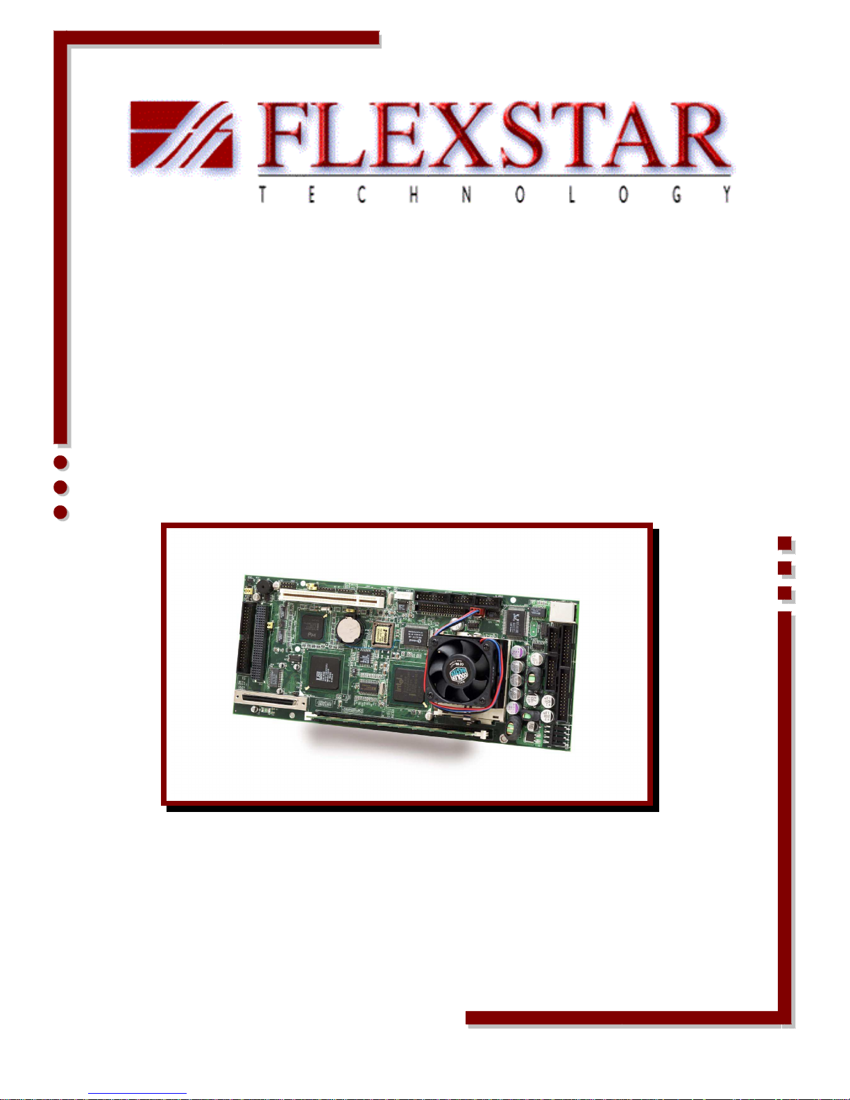
PEGASUS
PEGASUS
Single Board Computer (SBC)
User’s Guide
Doc # 98-37844-00 Rev. 1.1 02/12/02
Page 2

PEGASUS
Copyright Notice
This document is copyrighted, 2001 and all rights are reserved. FlexStar reserves the right to
make improvements to the products described in this manual at any time without notice. No part
of this manual may be reproduced, copied, translated or transmitted in any form or by any means
without the prior written permission of FlexStar. Information provided in this manual is intended to
be accurate and reliable. However, FlexStar assumes no responsibility for its use, or for any
infringements upon the rights of third parties that may result from its use.
Acknowledgements
Award is a trademark of Award Software International, Inc.
IBM, PC/AT, PS/2 and VGA are trademarks of International Business Machines Corporation.
Intel, Celeron, Pentium and Pentium II are trademarks of Intel Corporation.
Microsoft Windows ® is a registered trademark of Microsoft Corp.
RTL is a trademark of Realtek Semi-Conductor Co., Ltd.
Symbios is a trademark of Symbios Inc.
Winbond is a trademark of Winbond Electronics Corp.
All other product names or trademarks are properties of their respective owners.
For more information on this and other FlexStar products please visit our websites at:
http://www.FlexStar.com
For technical support and service for please visit our support website at:
h ttp://www.FlexStar.com/support
This manual is for the Flexstar Pegasus P/N 02-37177-00
02-37177-01
02-37177-02
02-37177-03
2
Page 3
PEGASUS
Packing List
Standard Items
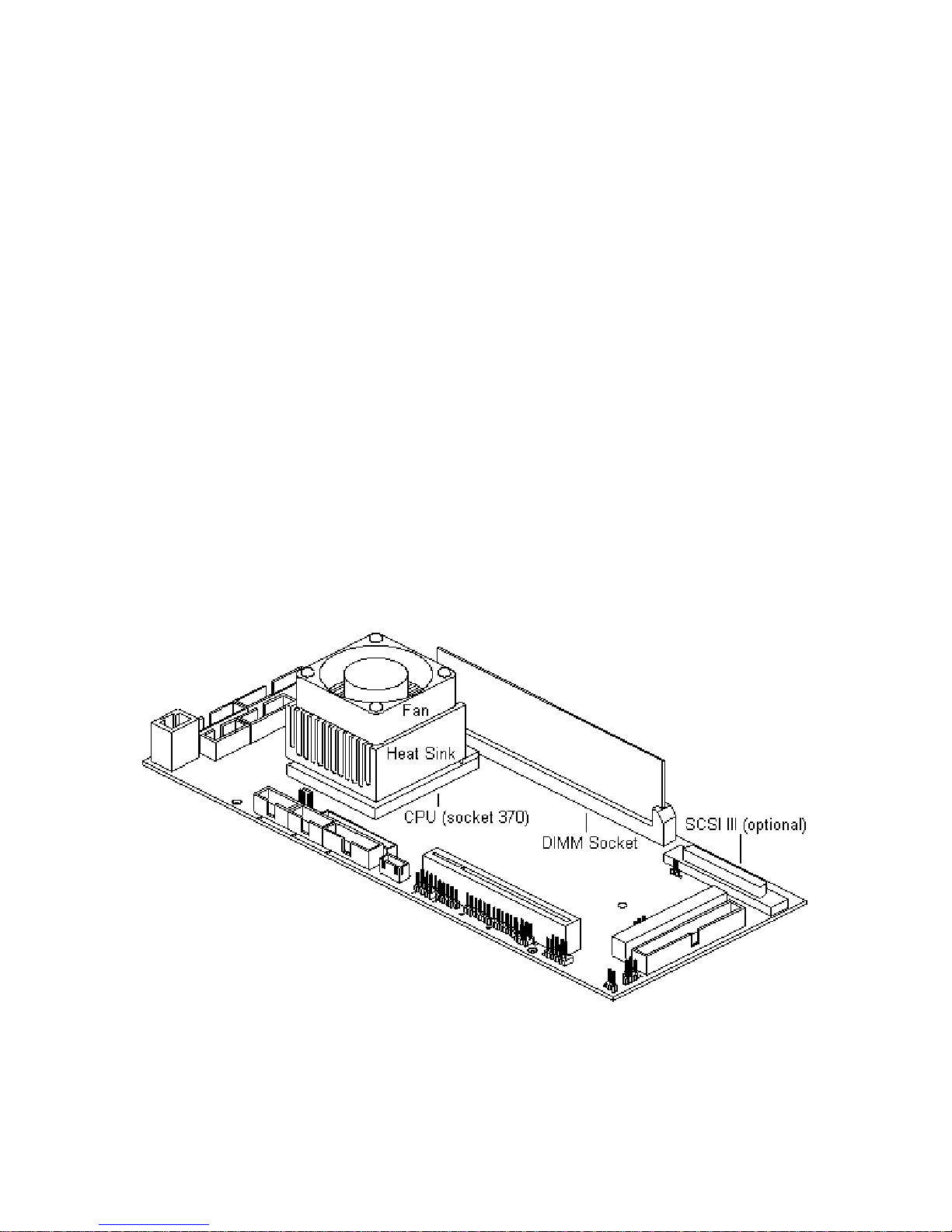
The basic Pegasus SBC contains a 733 Mhz Celeron CPU and 32MB of DRAM memory. Other
CPU types and speeds are available including the Pentium III processor (socket 370). Standard
DRAM memory is 32MB but the DIMM socket can support up to 256MB.
Pegasus SBC 02-37177-00.
733 MHz Celeron CPU.
64 MB DIMM memory.
CPU heat sink and cooling fan.
Pegasus Users Manual (this document) 98-37844-00.
Optional Items
Celeron or Pentium III CPU up to 850 Mhz.
Memory up to 256 MB.
On-board SCSI III controller (SE or LVD) using the LSI53C1010 chip.
One, two, or three slot PICMG riser card.
3
Page 4

PEGASUS
Table of Contents
1.0 Introduction
......................................................................................................................
8
2.0 Installation
......................................................................................................................
11
2.1 CPU Installation & Upgrade
......................................................................................................................
11
2.2 DRAM (DIMM) Installation & Upgrade
......................................................................................................................
11
2.3 Jumpers
......................................................................................................................
12
2.3.1 Locating Jumpers
......................................................................................................................
12
All option jumpers begin with the Jx designator. They can be located
as follows:
......................................................................................................................
12
2.3.2 Setting Jumpers
......................................................................................................................
13
2.3.2.1 Jumper J1 – Firmware Hub Lock\Unlock
......................................................................................................................
14
2.3.2.2 Jumper J2 – PC104 +VIO Select
......................................................................................................................
14
2.3.2.3 Jumper J3 – CMOS Battery Mode
......................................................................................................................
14
2.3.2.4 Jumper J4 – Reserved
......................................................................................................................
14
2.3.2.5 Jumper J5 – Reserved
......................................................................................................................
14
2.3.2.6 Jumper J6 – Internal Speaker
4
Page 5

PEGASUS
......................................................................................................................
14
2.3.2.7 Jumper J7 – IDE Tri-state Buffer Control
......................................................................................................................
14
2.3.2.8 Jumper J8 – PCI VIO & PCI PIN-A26 Select
......................................................................................................................
15
2.4 Connectors
......................................................................................................................
15
2.4.1 Locating Connectors
......................................................................................................................
16
2.4.2 CON1 – IDE Connector
......................................................................................................................
16
2.4.3 CN2 – Power Connector
......................................................................................................................
17
2.4.4 CN3 – SCSI Connector (Optional)
......................................................................................................................
17
2.4.5 CN4 – Parallel Port Connector
......................................................................................................................
18
2.4.6 CN5 – GPIO Connector
......................................................................................................................
18
2.4.7 CN6 – PC104 PLUS Connector
......................................................................................................................
19
2.4.8 CN7 – VGA & Keyboard Connector
......................................................................................................................
19
2.4.9 CN8 – PS/2 Mouse & Keyboard Connector
......................................................................................................................
19
2.4.10 CN9 – 10/100 Ethernet LAN Connector
......................................................................................................................
20
2.4.11 CN10 – COM-1 Connector
......................................................................................................................
20
2.4.12 CN11 – COM-2 Connector
5
Page 6

PEGASUS
......................................................................................................................
20
2.4.13 CN12 – Floppy Connector
......................................................................................................................
20
2.4.14 CN13 – Audio Connector
......................................................................................................................
21
2.4.15 CN14 – CD Line-In Connector
......................................................................................................................
21
2.4.16 CN15 – Front Panel Connector
......................................................................................................................
21
2.4.176 CN16 – USB Connector
......................................................................................................................
22
2.4.18 CN17 – IR Connector
......................................................................................................................
22
2.4.19 CN18 – IDE External Power Connector
......................................................................................................................
22
2.4.20 DIMM1 – DIMM Slot Connector
......................................................................................................................
23
2.4.21 FAN1 – CPU Fan Connector
......................................................................................................................
23
2.4.22 PCI1 – PCI Slot Connector
......................................................................................................................
23
3.0 Software Configuration
......................................................................................................................
24
3.1 Remote Boot LAN Configuration
......................................................................................................................
24
3.2 PCI SVGA Setup
......................................................................................................................
24
4.0 Award BIOS Configuration
......................................................................................................................
25
4.1 Entering Setup
6
Page 7

PEGASUS
......................................................................................................................
25
4.2 Standard CMOS Setup
......................................................................................................................
27
4.3 BIOS Features Setup
......................................................................................................................
28
4.4 Chipset Features Setup
......................................................................................................................
29
4.5 Power Management Setup
......................................................................................................................
30
4.6 PnP/PCI Configuration Setup
......................................................................................................................
31
4.7 Integrated Peripherals Setup
......................................................................................................................
32
4.8 Frequency / Voltage Control
......................................................................................................................
33
4.9 PC Health
......................................................................................................................
34
5.0 Programming the Watchdog Timer
......................................................................................................................
35
6.0 Technical Support
......................................................................................................................
36
7
Page 8

PEGASUS
1.0 Introduction
Pegasus is a highly integrated and self-contained Single Board Computer (SBC). Using a Socket
370 with the Intel 810 chip set, the Pegasus board will accept a full range of Intel Celeron and
Pentium III CPU’s up to 800 MHz. Pegasus’ performance is unmatched in its class with these
powerful yet cost effective Intel processors and a 168 pin DIMM slot for extra large memory
capacity.
On board features include two serial, one parallel, two USB and one 12 bit digital programmable I/
O ports. The on board PCI IDE interface supports one IDE device up to UDMA-66 and the
PCIMG expansion bus can support multiple devices with automatic Front Side Bus switching.
Also included are a floppy disk controller, high speed timer (1 us resolution), built in PS/2
keyboard and mouse ports, AC’97 audio, VGA and a 10/100 Base-T Ethernet port.
Flexstar also offers a wide array of options and accessories for the Pegasus. Ultra DMA 100/133,
Fibre Channel and various SCSI host bus adapters are available; along with programmable DC
voltage controllers with built in current and voltage monitor/capture functions. FlexStar also offers
a diskless remote boot software package for the ultimate in self contained and ruggedized
operation. Please visit FlexStar’s web site at www.flexstar.com for more details.
Pegasus Features
Socket 370 support for Intel Celeron and Pentium III
Intel 810 chip set including on board VGA controller
32 bit PCIMG bus supports automatic FSB switching and 2 PCI slots with riser card
On board PCI IDE interface supports Ultra DMA 66 with programmable tri-state control
32 bit PCI Plus connector for more PCI expansion
168 pin DIMM slot supports 8MB to 256MB DIMM’s
2 serial, one parallel and 1 digital I/O ports
2 USB ports, mouse and keyboard included
Floppy disk support
10/100 Base-T Ethernet
Programmable watch dog timer
Programmable high speed application timer
512KB Award BIOS with Intel 82802 Firmware Hub
AC ’97 audio codec
Optional on board SCSI controller
Optional programmable DC power controller with monitor/capture
Optional host bus adapters
Optional diskless, remote boot software
Pegasus Specifications
8
Page 9

PEGASUS
CPU Socket 370, Intel Celeron or Intel Pentium III
Chipset Intel 810 (Whitney) (GMCH0, ICH, FWH).
BIOS 512KB AWARD flash BIOS using Intel 82802 (FWH) Firmware
Hub.
Watch Dog Timer Programmable TCO timer on BIOS for recovering software or
hardware lockout (2.4 sec. Interval), or external watchdog timer.
DRAM One 168 pin DIMM socket supports 8MB to 256MB DIMM.
PCI IDE Interface Enhanced IDE interface supports two IDE devices in PIO mode 3,4
with bus mastering up to 16MB/sec. And Ultra DMA 66 at
66MB/sec. Burst rate.
PCI Expansion One PCIMG expansion slot supporting three devices plus one PC/
104+PCI connector (not to be used concurrently). PCI Rev. 2.2
compliant.
Floppy Disk Interface Yes
Parallel Port One, supporting EPP and ECP mode, may be used an 8 bit digital
output.
Serial Ports Two RS-232
Digital I/O 12 bit programmable at 5V
Super I/O Chip Winbond W83627 128 pin Super I/O Controller with LPC interface.
VGA Built into Intel 810 chip set (D.V.M. architecture).
Ethernet IEEE 802.3u 10/100BASE-T PCI Ethernet via Realtek RTL 8139A.
Remote boot available.
USB 2 Universal Serial Bus ports, USB UHCI 1.0 compliant.
Keyboard/Mouse On board pin header connector for PS/2 keyboard and PS/2
mouse.
Audio AC’97 2.1 compliant link for audio codec.
SSD None.
Reset Switch On board header pins.
IDE Tri-State On board with program control or external control.
Power Requirements 5VDC at 5 Amps and 12VDC at 0.25 Amps.
Power Connector Molex 26-46-1046 or exact equivalent.
Operating Temperature 5C to 45C.
Dimensions 4.5”W x 11”L.
Weight 0.8 LBS w/CPU, heat sink, & memory.
High Speed Timer 1MHZ clocked 16 bits.
Buzzer Yes
Battery
CR2032 battery (NOTE: battery has a limited life of 10,000 hours.
The Pegasus uses a CR2032 battery, which is used to maintain the
CMOS when the unit is powered off. The battery has a life of
approximately 10,000 hours. How many months the battery is good
for depends on how many hours the unit is ON or OFF.)
9
Page 10
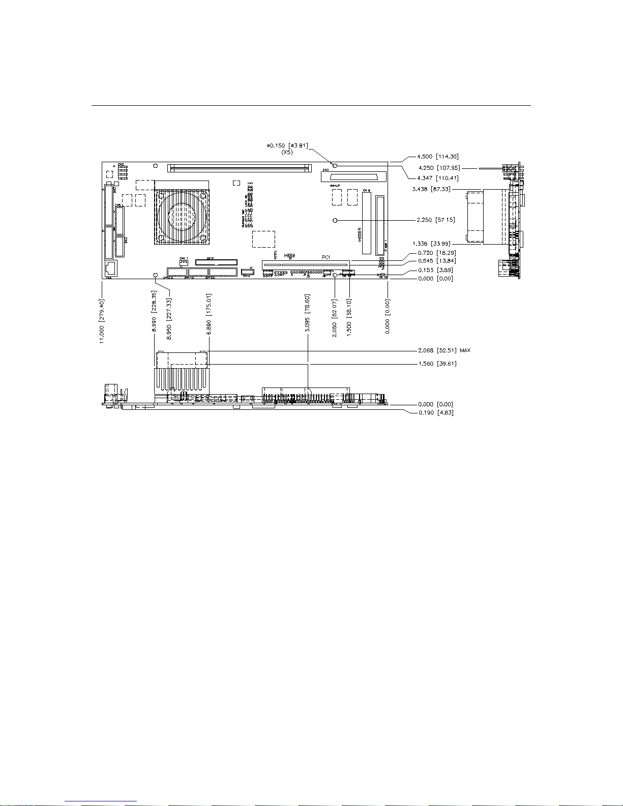
Pegasus Board Layout and Dimensions
PEGASUS
Figure 1-1
10
Page 11
2.0 Installation
This chapter explains how to set up the Pegasus hardware, including instructions on setting
jumpers and connecting peripherals, switches and indicators. Be sure to read all the safety
precautions before you begin the installation procedure.
Always disconnect the power cord from Pegasus when you are working on it.
Do not make connections while the power is on as sensitive electronic
components can be damaged by the sudden rush of power. Only experienced
electronics personnel should install and/or maintain Pegasus.
Always ground yourself to remove any static charge before touching the PC
board. Modern electronic devices are very sensitive to static electric charges.
Use a grounding wrist strap at all times. Place all electronic components on a
static-dissipative surface or in a static-shielded bag when they are not in the
chassis.
2.1 CPU Installation & Upgrade
The Pegasus provides a Zero Insertion Force (ZIF) socket (socket 370 type) for easy CPU
installation.
1. Make sure the ZIF socket lever is in the upright position. To raise the lever, pull it out to
the side a little and raise it as far as it will go.
2. Place the CPU in the empty socket. Follow the instructions that came with the CPU. If you
have no instructions, do the following:
3. Carefully align the CPU so it is parallel to the socket and the notch on the corner of the
CPU corresponds with the notch on the inside of the socket. Gently slide the CPU in. It
should insert easily. If it doesn‘t, it is probably not installed correctly or the lever is not fully
released.
4. Press the lever down. The plate will slide forward. You will feel some resistance as the
pressure starts to secure the CPU in the socket. This is normal and will not damage the
CPU.
When the CPU is installed, the lever should snap into place at the side of the socket.
Note: To remove a CPU, pull the lever out to the side a little and raise it as far as it will go. Lift out
the CPU chip.
Note also that the CPU clock speed and operating voltage is automatically detected by the SBC
and there are no jumper options for these settings.
2.2 DRAM (DIMM) Installation & Upgrade
Doc # 98-37844-00 Rev. 1.1 02/12/02
Page 12

PEGASUS
You can install anywhere from 8MB to 256MB of on-board DRAM memory using one 8, 16, 32,
64, 128 or 256MB 168-pin DIMM. Note: The modules can only fit into a socket one way and
their gold fingers must point down into the DIMM socket. The procedure for installing DIMMs
appears below. Please follow these steps carefully.
1. Ensure that all power supplies to the system are switched off.
2. Locate the DIMM near the Pegasus DIMM socket so that its gold fingers point down into the
DIMM socket.
3. The DIMM module has two notches on its edge connector. Ensure that the notches are facing
away from the CPU.
4. Gently push the DIMM vertically down until the ejector tabs of the DIMM sockets snap into
place.
2.3 Jumpers
The Pegasus SBC contains various jumpers that allow configuration of the board to suit your
application. Table 2-1 lists the function of each Pegasus jumper:
Jumper Function
J1 Firmware hub lock\unlock
J2 PC104 +VIO select
J3 CMOS battery normal\clear CMOS
J4 CPLD Program Connector
J5 CPLD Program Connector
J6 Internal speaker enable\disable
J7 IDE tri-state buffer control
J8 PCI VIO select and PCI pin A26 select
Table 2-1
2.3.1 Locating Jumpers
All option jumpers begin with the Jx designator. They can be located as follows:
12
Page 13
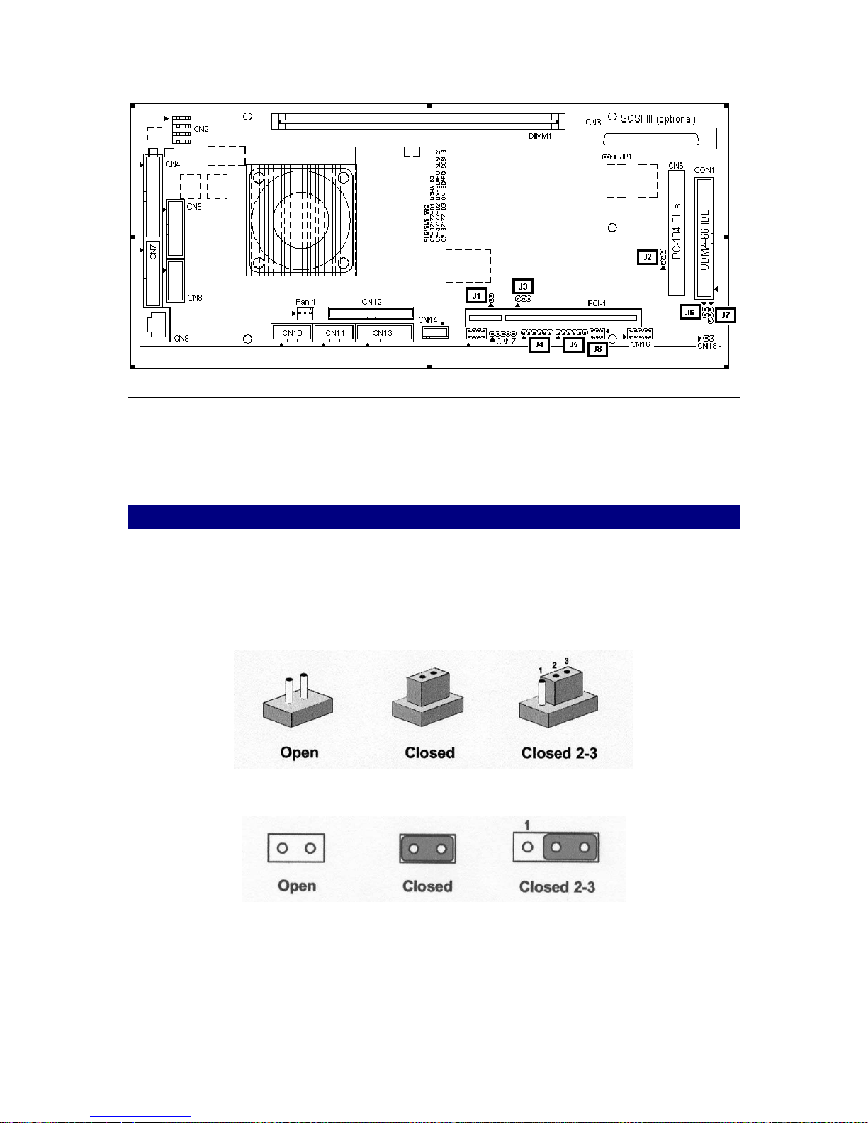
Figure 2-1
PEGASUS
2.3.2 Setting Jumpers
The option jumpers configure the Pegasus to match the needs of your application. A jumper is the
simplest kind of electric switch. It consists of two metal pins and a small metal clip (often
protected by a plastic cover) that slides over the pins to connect them. To “close” a jumper you
connect the pins with the clip. To “open” a jumper you remove the clip. Sometimes a jumper will
have three pins, labeled 1, 2, and 3. In this case you would connect either pins 1 and 2 or 2 and 3.
The jumpers are represented in this manual as follows:
A pair of needle-nose pliers is helpful when working with jumpers. If you have any doubts about
the best hardware configuration for your application, contact your local FlexStar distributor or
technical support representative before you make any changes.
13
Page 14
PEGASUS
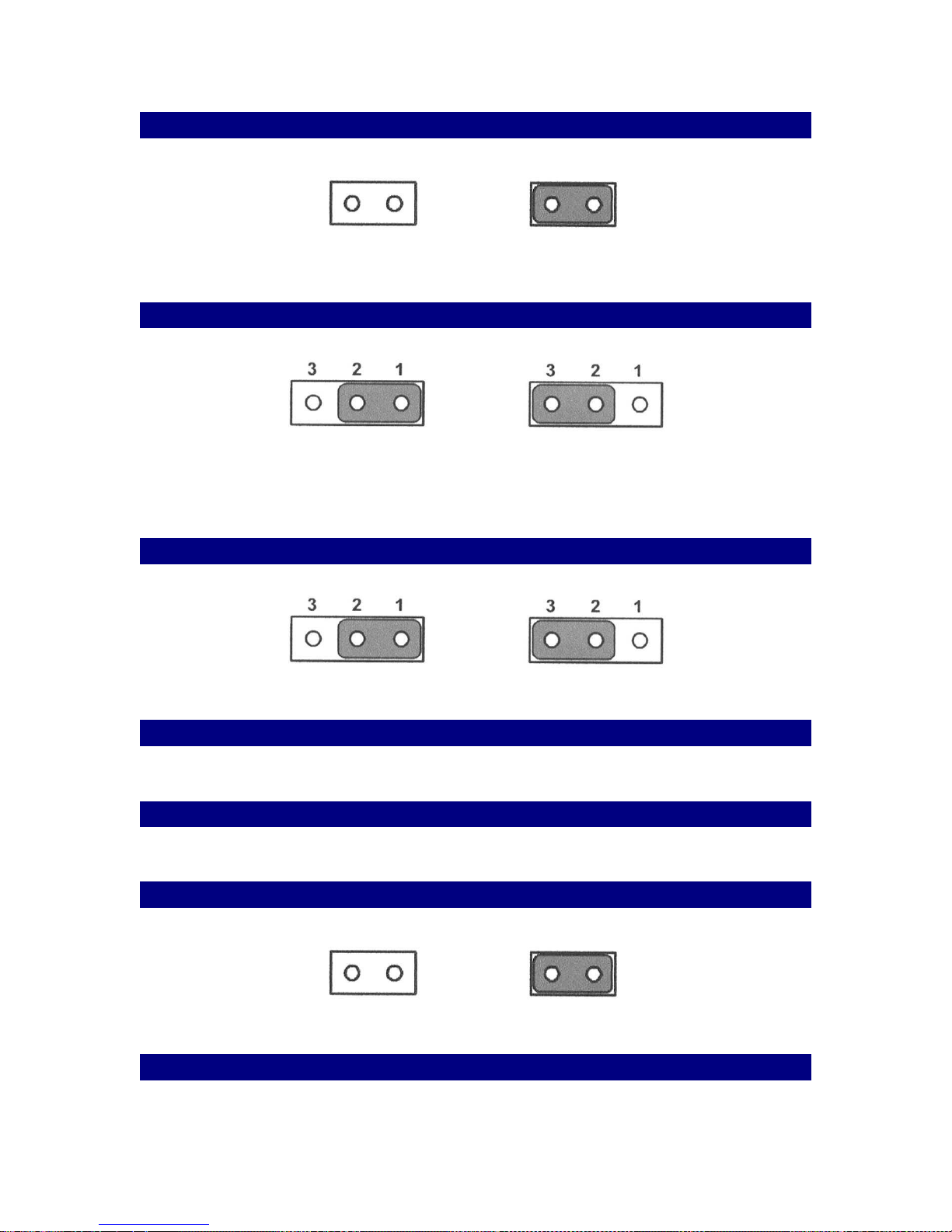
2.3.2.1 Jumper J1 – Firmware Hub Lock\Unlock
Locked Unlocked
2.3.2.2 Jumper J2 – PC104 +VIO Select
+5V Select +3.3V Select
2.3.2.3 Jumper J3 – CMOS Battery Mode
Normal Clear CMOS
2.3.2.4 Jumper J4 – Reserved
2.3.2.5 Jumper J5 – Reserved
2.3.2.6 Jumper J6 – Internal Speaker
Disable Enable
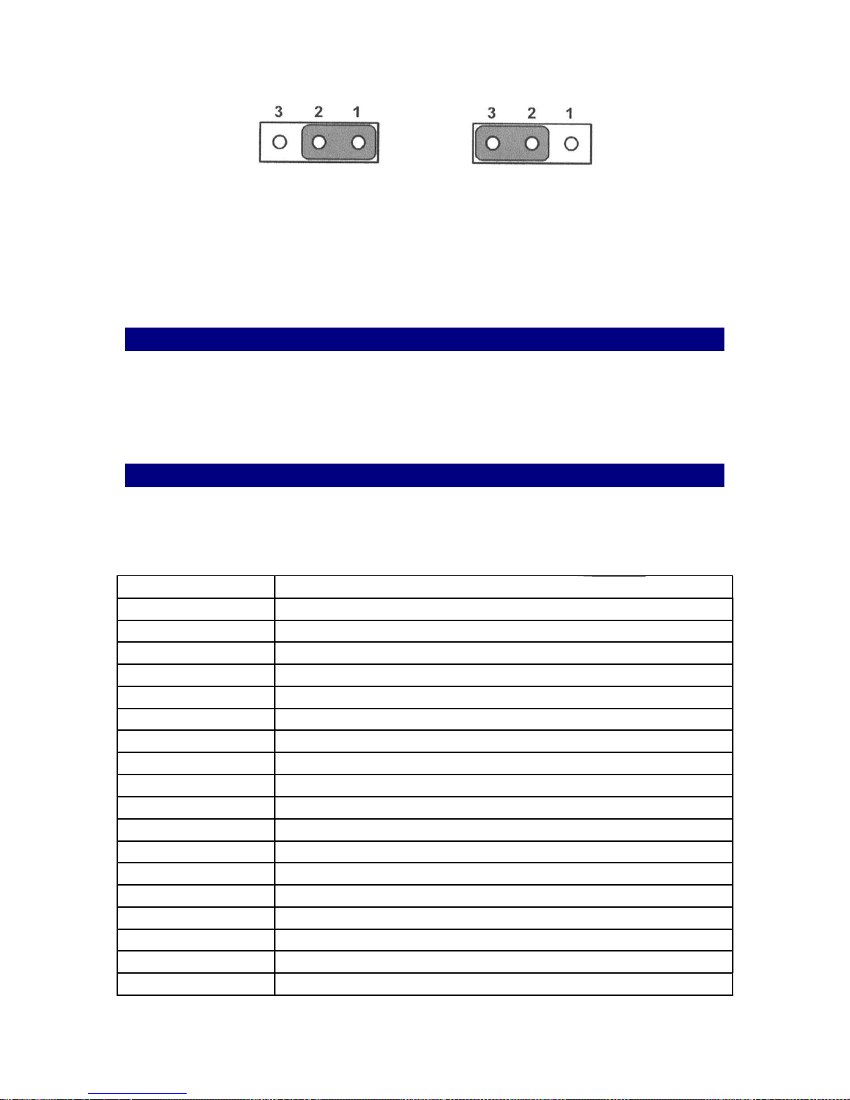
2.3.2.7 Jumper J7 – IDE Tri-state Buffer Control
14
Page 15
PEGASUS
IDE buffer uses internal
power, CN18 cannot
control IDE buffer off.
IDE buffer uses external
power. If CN18 PIN-1 input
is +5V then IDE buffer is on
(LowZ). IF CN18 PIN-1 is 0V
then IDE buffer is off
(HighZ).
2.3.2.8 Jumper J8 – PCI VIO & PCI PIN-A26 Select
PIN-1 & PIN-3 Short : PCI Pin-A26 is PGNT#3
PIN-3 & PIN-5 Short : PCI Pin-A26 is AD29
PIN-2 & PIN-4 Short : PCI SLOT VIO is select +5V
PIN-4 & PIN-6 Short : PCI SLOT VIO is select +3.3V
2.4 Connectors
On-board connectors link the Pegasus SBC to external devices such as hard disk drives,
keyboard, floppy drives, USB, etc. The table below lists the function of each of the board’s
connectors:
CON1 IDE connector
CN2 Power connector
CN3 SCSI connector
CN4 Parallel port connector
CN5 GPIO connector
CN6 PC104 Plus connector
CN7 VGA & keyboard connector
CN8 PS/2 mouse & keyboard connector
CN9 10/100 LAN connector
CN10 COM-1 connector
CN11 COM-2 connector
CN12 Floppy connector (reserved)
CN13 Audio connector
CN14 CD in-line connector
CN15 Front panel connector
CN16 USB connector
CN17 IR connector
CN18 IDE external power connector
DIMM1 DIMM socket
15
Page 16
FAN1 CPU fan connector
PCI1 PCI expansion slot connector
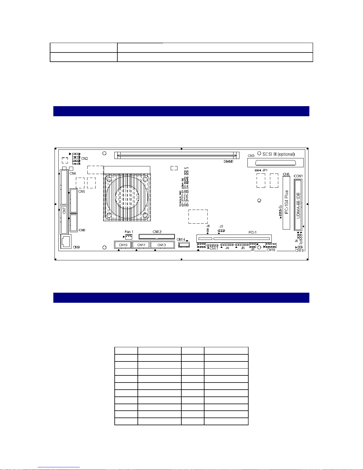
2.4.1 Locating Connectors
PEGASUS
Table 2-2
Figure 2-2
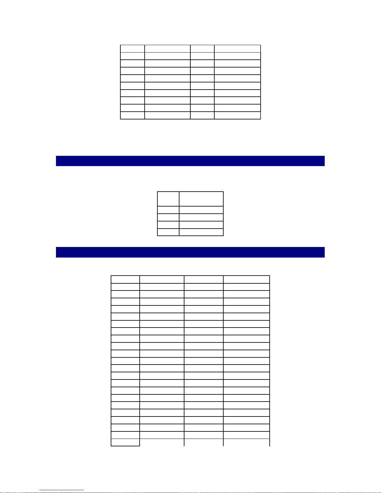
2.4.2 CON1 – IDE Connector
CON1 allows attachment of one or two Enhanced Integrated Device Electronics hard disk drives
to the Pegasus Intel 810 internal controller. This controller uses a PCI local-bus interface and
supports PIO mode 3 and mode 4 with bus mastering up to 16MB/sec. It also support Ultra DMA
operation up to 66MB/sec.
Pin # Signal Name Pin # Signal Name
1 RESET 2 GND
3 DD7 4 DD8
5 DD6 6 DD9
7 DD5 8 DD10
9 DD4 10 DD11
11 DD3 12 DD12
13 DD2 14 DD13
15 DD1 16 DD14
17 DD0 18 DD15
19 GND 20 KEY
16
Page 17
PEGASUS
21 DMARQ 22 GND
23 DIOW 24 GND
25 DIOR 26 GND
27 IORDY 28 SS
29 DMACK 30 GND
31 INTRQ 32 IOCS16
33 DA1 34 PDIAG
35 DA0 36 DA2
37 CS1 38 CS3
39 DASP 40 GND
2.4.3 CN2 – Power Connector
Supplies main power to the Pegasus (+5 V) and devices that require +12 V.
Pin#Signal
Name
1 +12V
2 GND
3 GND
4 +5V
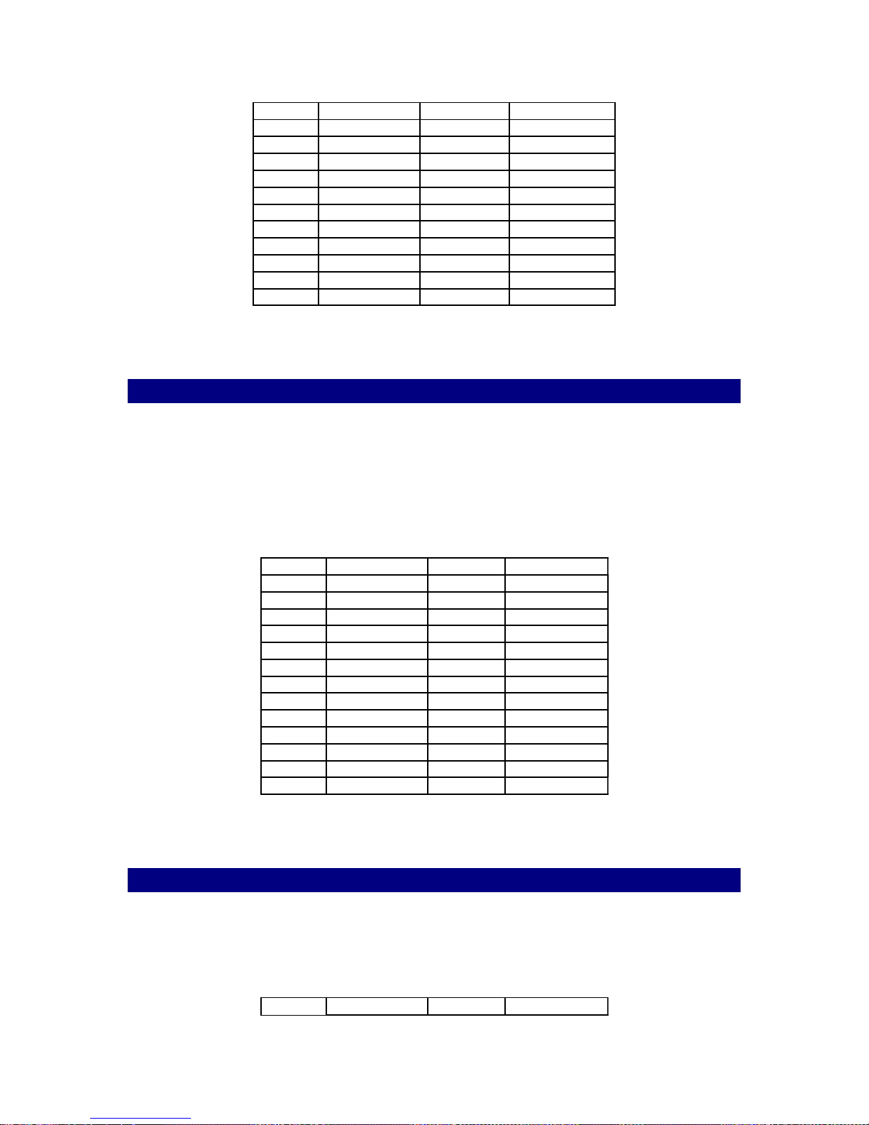
2.4.4 CN3 – SCSI Connector (Optional)
Pin # Signal Name Pin # Signal Name
1 +DB12 2 +DB13
3 +DB14 4 +DB15
5 +DB(P1) 6 GND
7 +DB0 8 +DB1
9 +DB2 10 +DB3
11 +DB4 12 +DB5
13 +DB6 14 +DB7
15 +DB(P) 16 DIFFSENS
17 TERMPWR 18 TERMPWR
19 RESERVED 20 +ATN
21 GND 22 +BSY
23 +ACK 24 +RST
25 +MSG 26 +SEL
27 +C/D 28 +REQ
29 +I/O 30 GND
31 +DB8 32 +DB9
33 +DB10 34 +DB11
35 -DB12 36 -DB13
37 -DB14 38 -DB15
39 -DB(P1) 40 GND
41 -DB0 42 -DB1
43 -DB2 44 -DB3
17
Page 18
PEGASUS
45 -DB4 46 -DB5
47 -DB6 48 -DB7
49 -DB(P) 50 GND
51 TERMPWR 52 TERMPWR
53 RESERVED 54 -ATN
55 GND 56 -BSY
57 -ACK 58 -RST
59 -MSG 60 -SEL
61 -C/D 62 -REQ
63 -I/O 64 GND
65 -DB8 66 -DB9
67 -DB10 68 -DB11
2.4.5 CN4 – Parallel Port Connector
The parallel port may be used to connect a printer. The Pegasus includes a multi-mode
(ECP/EPP/SPP) parallel port, accessed through CN4, a 26-pin flat-cable connector. You will need
an adapter cable if you use a traditional DB-25 connector. The adapter cable has a 26-pin
connector on one end and a DB-25 connector on the other. The parallel port is designated as
LPT1 and can be disabled or changed to LPT2 or LPT3 in the system BIOS setup. The parallel
port interrupt channel is designated to be IRQ7. You can select ECP/EPP DMA channel via BIOS
setup.
Pin # Signal Name Pin # Signal Name
1 /STROBE 2 AUTOFD
3 D0 4 ERROR
5 D1 6 INIT
7 D2 8 SLIN
9 D3 10 GND
11 D4 12 GND
13 D5 14 GND
15 D6 16 GND
17 D7 18 GND
19 /ACK 20 GND
21 BUSY 22 GND
23 PE 24 GND
25 SLCT 26 GND
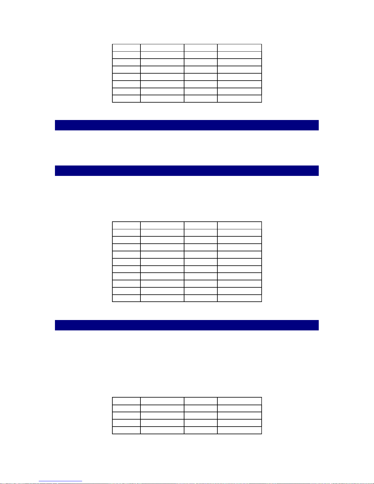
2.4.6 CN5 – GPIO Connector
The Pegasus board also contains a GPIO (General Purpose I/O) port that can be used to control
and/or monitor an external custom piece of hardware. Fourteen (14) are available for custom
control. The GPIO bits 0 - 7 are read/written through the Super I/O chip W83627 GP1 register bits
0 – 7. GPIO bits 8 – 15 are read/written through the Super I/O chip’s GP3 register bits 0 – 7. The
pinout for CN5 is as follows:
Pin # Signal Name Pin # Signal Name
18
Page 19
PEGASUS
1 GPIO0 2 GPIO8
3 GPIO1 4 GPIO9
5 GPIO2 6 GPIO10
7 GPIO3 8 GPIO11
9 GPIO4 10 GPIO12
11 GPIO5 12 GPIO13
13 GPIO6 14 GND
15 GPIO7 16 GND
2.4.7 CN6 – PC104 PLUS Connector
Pegasus allows the addition of PC104 Plus compatible devices via CN6. The PC104 Plus bus is
a PCI compatible bus that utilizes a PC104 stackable type interface connector.
2.4.8 CN7 – VGA & Keyboard Connector
The Pegasus PCI SVGA interface can drive conventional CRT displays and is capable of driving a
wide range of flat panel displays, including electro luminescent (EL), gas plasma, passive LCD
and active LCD displays. The board has two connectors to support these displays, one for
standard CRT VGA monitors and one for flat panel displays. Note that this connector also
supports a keyboard and that the keyboard signals are duplicated on CN8.
Pin # Signal Name Pin # Signal Name
1 VGA-R 2 VGA-GND
3 VGA-G 4 VGA-GND
5 VGA-B 6 VGA-GND
7 VGA-GND 8 VGA-DATA
9 VGA-GND 10 VGA-H
11 VGA-GND 12 VGA-V
13 VGA-GND 14 VGA-CLK
15 VGA-GND 16 N.C.
17 KB-CLK 18 KB-DATA
19 KB-VCC 20 GND
2.4.9 CN8 – PS/2 Mouse & Keyboard Connector
The Pegasus board provides a keyboard connector that supports both a keyboard and a PS/2
style mouse. In some cases, especially in embedded applications, a keyboard and/or mouse may
not be used. The standard PC/AT BIOS will report an error or fail during power-on self-test
(POST) after a reset if the keyboard is not present. The Pegasus BIOS standard setup menu
allows you to select “All, But Keyboard” under the “Halt On” selection. This allows no-keyboard
operation in embedded system applications without the system halting under POST (power-onself-test).
Pin # Signal Name Pin # Signal Name
1 PS2-CLK 2 KB-CLK
3 PS2-DATA 4 KB-DATA
5 VCC 6 VCC
7 GND 8 GND
19
Page 20
PEGASUS
9 N.C. 10 N.C.
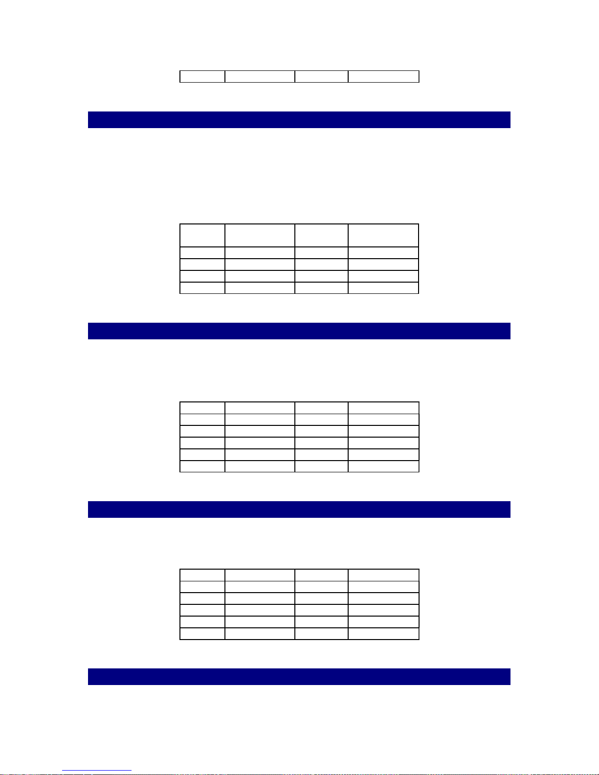
2.4.10 CN9 – 10/100 Ethernet LAN Connector
The Pegasus is equipped with a high performance 32-bit PCI-bus Ethernet interface, which is fully
compliant with IEEE 802.3U 10/100Mbps CSMA/CD standards. It is supported by all major
network operating systems. 10 or 100Base-T connects to the Pegasus via an adapter cable to a
10-pin polarized header (CN9). For 10Base-T RJ-45 operation, an adapter cable converting CN9
into a standard RJ-45 jack is required.
Pin # Signal
Name
1 XMIT+ 2 XMIT3 RCV+ 4 N/A
5 N/A 6 RCV7 N/A 8 N/A
Pin # Signal Name
2.4.11 CN10 – COM-1 Connector
The Pegasus provides two serial RS-232 ports. The COM-1 port connector is a 10-pin, dual-inline, male header and provides connections for serial devices (a mouse, etc.) or a communication
network.
Pin # Signal Name Pin # Signal Name
1 DCD 2 DSR
3 RXD 4 RTS
5 TXD 6 CTS
7 DTR 8 RI
9 GND 10 N.C.
2.4.12 CN11 – COM-2 Connector
The Pegasus provides two serial RS-232 ports. The COM-2 port connector is a 10-pin, dual-inline, male header and provides connections for serial devices or a communication network.
Pin # Signal Name Pin # Signal Name
1 DCD 2 DSR
3 RXD 4 RTS
5 TXD 6 CTS
7 DTR 8 RI
9 GND 10 N.C.
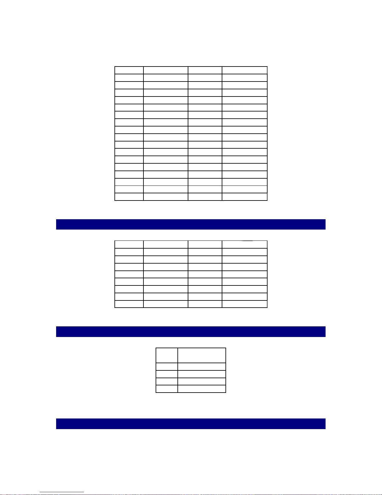
2.4.13 CN12 – Floppy Connector
20
Page 21
PEGASUS
The Pegasus SBC has full support for 1.44 MB floppy disk drives. The pinout of the Floppy Drive
connector CN12 is as follows:
Pin # Signal Name Pin # Signal Name
1 GND 2 WRT CUR
3 GND 4 N/A
5 GND 6 N/A
7 GND 8 INDEX
9 GND 10 MOTOR A
11 GND 12 SEL A
13 GND 14 SEL B
15 GND 16 MOTOR B
17 GND 18 DIR
19 GND 20 STEP PLS
21 GND 22 WRT DATA
23 GND 24 WRT ENB
25 GND 26 TRK0
27 GND 28 WRT PROT
29 GND 30 RD DATA
31 GND 32 HD SEL
33 GND 34 DISK CHG
2.4.14 CN13 – Audio Connector
Pin # Signal Name Pin # Signal Name
1 N.C. 2 N.C.
3 N.C. 4 N.C.
5 LINE OUT R 6 LINE OUT L
7 GND 8 GND
9 LINE IN R 10 LINE IN L
11 GND 12 GND
13 N.C. 14 N.C.
15 MIC IN 16 GND
2.4.15 CN14 – CD Line-In Connector
Pin#Signal Name
1 CD LINE IN L
2 GND
3 CD LINE IN R
4 GND
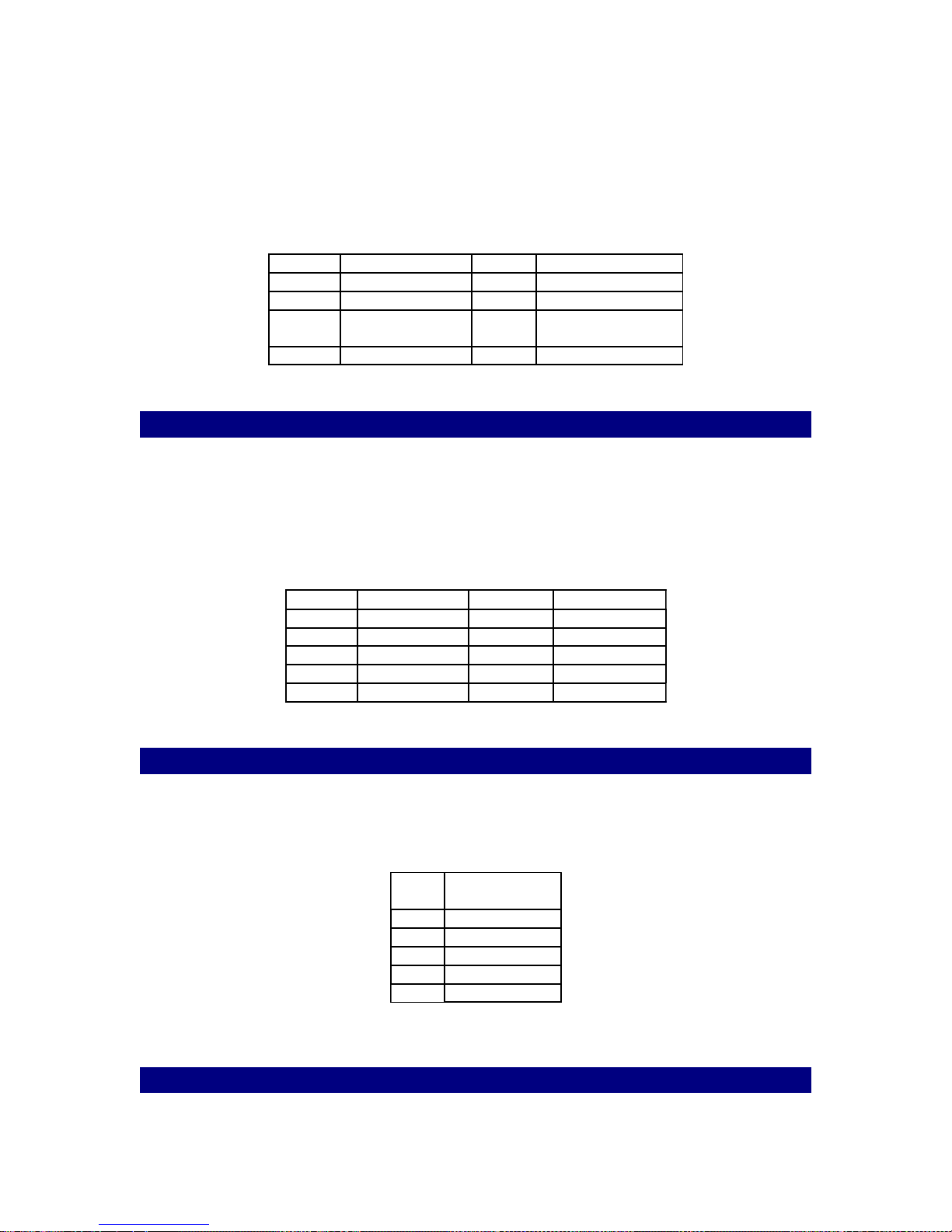
2.4.16 CN15 – Front Panel Connector
The front panel connector contains input and output options to monitor and control the Pegasus
SBC. The features are optional - install them only if you need them. The front panel connector
21
Page 22
PEGASUS
(CN15) is an 8-pin male, dual in-line header and provides connections for a speaker, hard disk
access indicator, watchdog output and an input switch for resetting the card.
The Pegasus can drive an 8 ohm speaker at 0.5 watts. Make sure that alternatives to this
specification do not overload the card. The front panel LED indicator for hard disk access is an
active low signal (24 ma sink rate). When the Pegasus watchdog timer times out, the front panel
pin 6 will output an active low pulse signal (25mA sink for 1 second).
Pin # Signal Name Pin # Signal Name
1 LED - 2 LED+
3 EXT. SPEAKER 4 EXT. SPEAKER
5 GND 6 WATCHDOG
ACTIVE OUT
7 RESET/GND 8 RESET N/O
2.4.176 CN16 – USB Connector
The Pegasus board provides two USB (Universal Serial Bus) interfaces which gives complete
plug and play, hot attach/detach for up to 127 external devices. The USB interfaces comply with
USB specification rev. 1.0 and are fuse protected. The USB interfaces are accessed through two
4-pin flat-cable connectors, CN16. You will need an adapter cable if you use a standard USB
connector. The adapter cable has a 4-pin connector on one end and an USB connector on the
other. The USB interfaces can be disabled in the system BIOS setup.
Pin # Signal Name Pin # Signal Name
1 USB1 VCC 2 USB2 VCC
3 USB1 P- 4 USB2 P5 USB1 P+ 6 USB2 P+
7 USB1 GND 8 USB2 GND
9 USB GND 10 N.C.
2.4.18 CN17 – IR Connector
The Pegasus provides an IrDA port for transfer rates of 115 Kbps. This connector supports the
optional wireless infrared transmitting and receiving module. You must configure the setting
through BIOS setup.
Pin#Signal Name
1 VCC
2 N.C.
3 IR-RX
4 GND
5 IR-TX
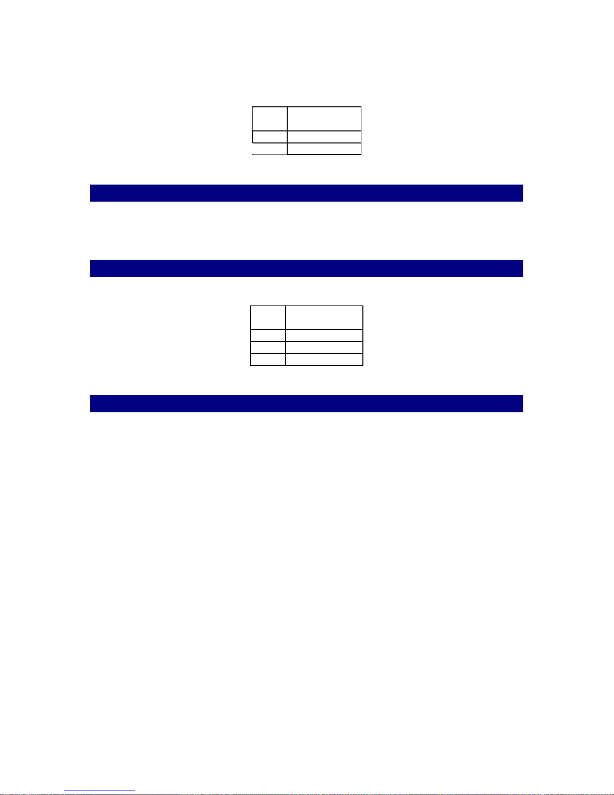
2.4.19 CN18 – IDE External Power Connector
22
Page 23
PEGASUS
This connector is used to externally control the on-board IDE tri-state buffers (see also section 2.3
Jumpers).
Pin#Signal Name
1 +5V INPUT
2 GND
2.4.20 DIMM1 – DIMM Slot Connector
The DRAM memory used on the Pegasus is of the synchronous PC-100 DIMM type and the
Pegasus can accept up to 256 MB’s of memory.
2.4.21 FAN1 – CPU Fan Connector
Provides power to the CPU cooling fan.
Pin#Signal Name
1 N.C.
2 +12V
3 GND
2.4.22 PCI1 – PCI Slot Connector
The Pegasus comes equipped with one standard PCI expansion slot. A 1, 2, or 3 slot riser is
available for converting the PCI card mounting from vertical to horizontal and adds expansion
capability for up to three PCI cards.
23
Page 24

PEGASUS
3.0 Software Configuration
The Pegasus system BIOS and Remote Boot code is located in a 512 KB, 32-pin PLCC Flash
ROM device, designated U15. A single Flash chip holds the system BIOS, VGA BIOS, and
network Remote Boot code. All peripherals are configured via CMOS settings. This method
minimizes the number of chips and difficultly of configuration.
3.1 Remote Boot LAN Configuration
The Pegasus SBC is equipped with a high performance 32-bit Ethernet chipset, which is fully
compliant with IEEE 802.3 100 Mbps CSMA/CD standards. It is supported by all major network
operating systems. It is also both 100Base-T and 10Base-T compatible.
The Ethernet port provides a standard RJ-45 jack on board. The Ethernet device is also used to
remote boot the Pegasus in embedded applications (no HDD). The network boot feature is
combined within the system BIOS, which can be enabled/disabled in the BIOS setup. To setup the
BIOS correctly for remote booting, use the following procedure:
1. Boot up the Pegasus board with keyboard and monitor attached and press the DEL key to
enter the BIOS setup
2. Enter the ADVANCED BIOS FEATURES menu and se the following:
a) FIRST BOOT DEVICE = LAN.
b) SECOND BOOT DEVICE = FLOPPY.
c) THIRD BOOT DEVICE = HDD-0.
d) OTHER BOOT DEVICE = Enable.
3. Enter the INTEGRATED PERIPHERALS menu and set the following:
a) ON BOARD SCSI BOOT ROM = Disabled.
b) RPL LAN ROM RETRY TIMER = 125.
3.2 PCI SVGA Setup
The Pegasus has an on-board PCI SVGA interface via the Intel 810 chipset. The specifications
and features are described as follows:
The Pegasus uses the Intel 810 chipset for its PCI/SVGA controller. It supports most conventional
analog CRT monitors and flat panel displays that accept the standard VGA interface. The VGA
controller can drive CRT displays or color flat panel displays with resolutions up to 800 x 600 at
64K colors.
The only BIOS setup for the video is inside the STANDARD CMOS SETUP menu:
VIDEO = EGA/VGA.
24
Page 25

PEGASUS
4.0 Award BIOS Configuration
Award’s BIOS ROM has a built-in Setup program that allows users to modify the basic system
configuration. This type of information is stored in battery-backed CMOS RAM so that it retains
the Setup information when the power is turned off.
Note: The battery, a CR2032, is a non-rechargeable with an expected life of 10,000
hours when the board is powered off.
4.1 Entering Setup
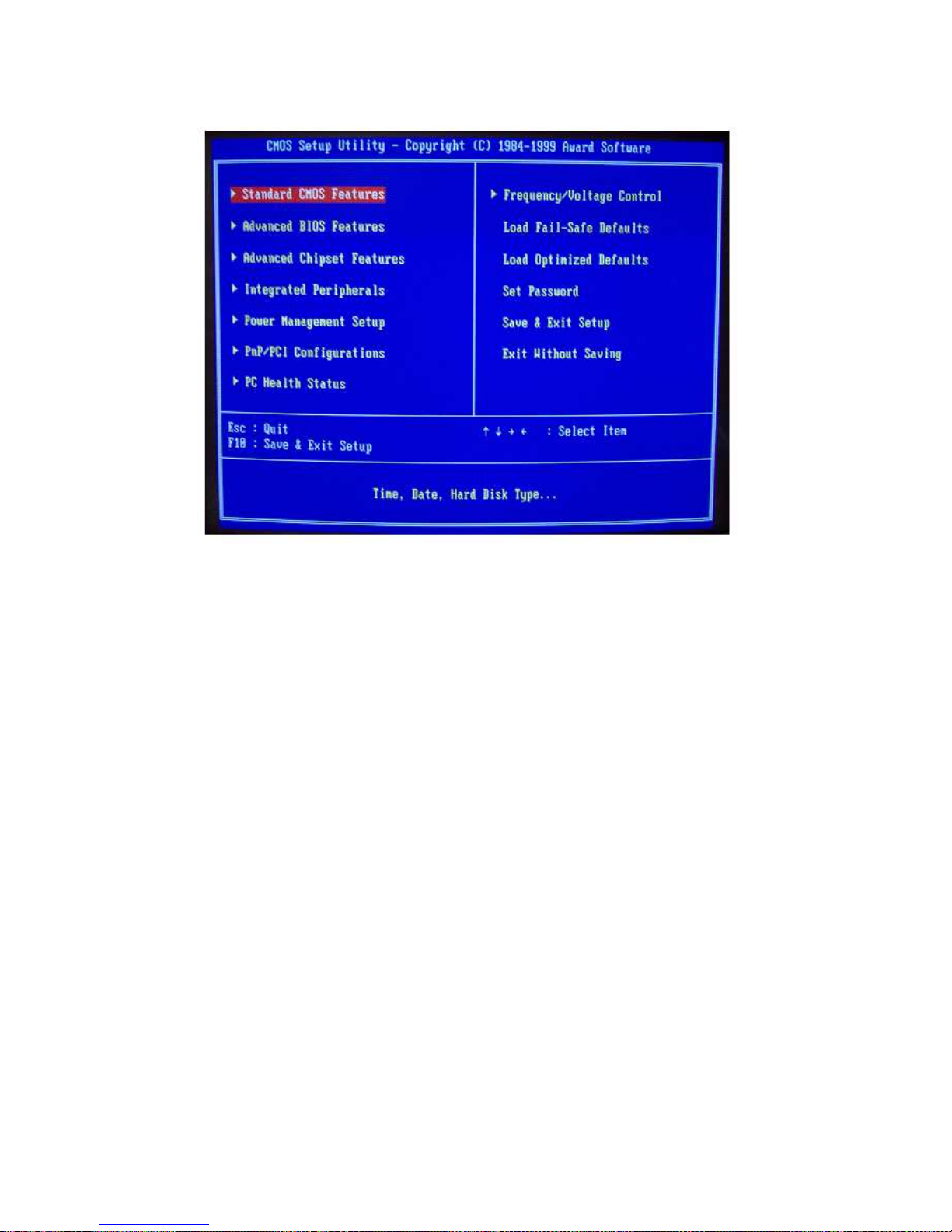
Power on or reset the Pegasus and press <Del> immediately after the post boot-up BEEP. This
will allow you to enter Setup. The main setup menu contains a number of sub-menus each
denoted by a bullet on the left side of the menu name. There are also five direct menu functions:
Load Fail-Safe Defaults:
Select this function to reload all BIOS menu settings with the most conservative default values.
Note: Fail safe defaults are used for debugging purposes only.
Load Optimized Defaults:
Select this function to reload all BIOS menu items with all the default settings.
Set Password:
A password may be set to prevent un-authorized booting and operation. This password protection
only prevents the user from entering the setup menu. Note that the password protection may be
reset by clearing the CMOS memory via jumper J3.
Save & Exit Setup:
The SAVE & EXIT SETUP function allows any changes that may have been made to the BIOS
setup to be saved in non-volatile CMOS memory. After the changes are saved, the Pegasus will
re-boot.
Exit Without Saving:
This function will simply cause the Pegasus to re-boot without saving any changes made to any of
the setup menu items.
25
Page 26
PEGASUS
Figure 4-1
NOTE: Fail safe defaults are used for debugging purposes only.
26
Page 27
PEGASUS
4.2 Standard CMOS Setup
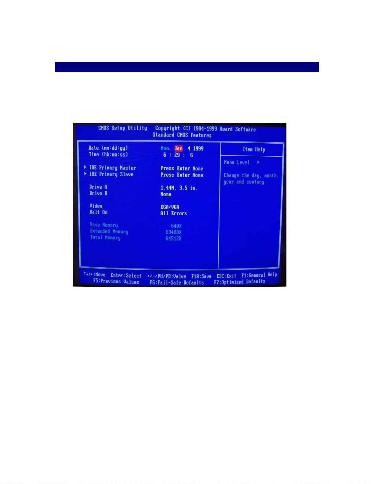
When you choose the STANDARD CMOS SETUP option from the MAIN SETUP SCREEN menu,
the screen shown below is displayed. This standard Setup Menu allows users to configure system
components such as date, time, hard disk drive, floppy drive and display. Once a field is
highlighted, on-line help information is displayed in the left bottom of the Menu screen.
Note that when the CMOS memory is cleared via J3, the DATE is reset Jan 1, 1999.
Figure 4-2
27
Page 28
PEGASUS
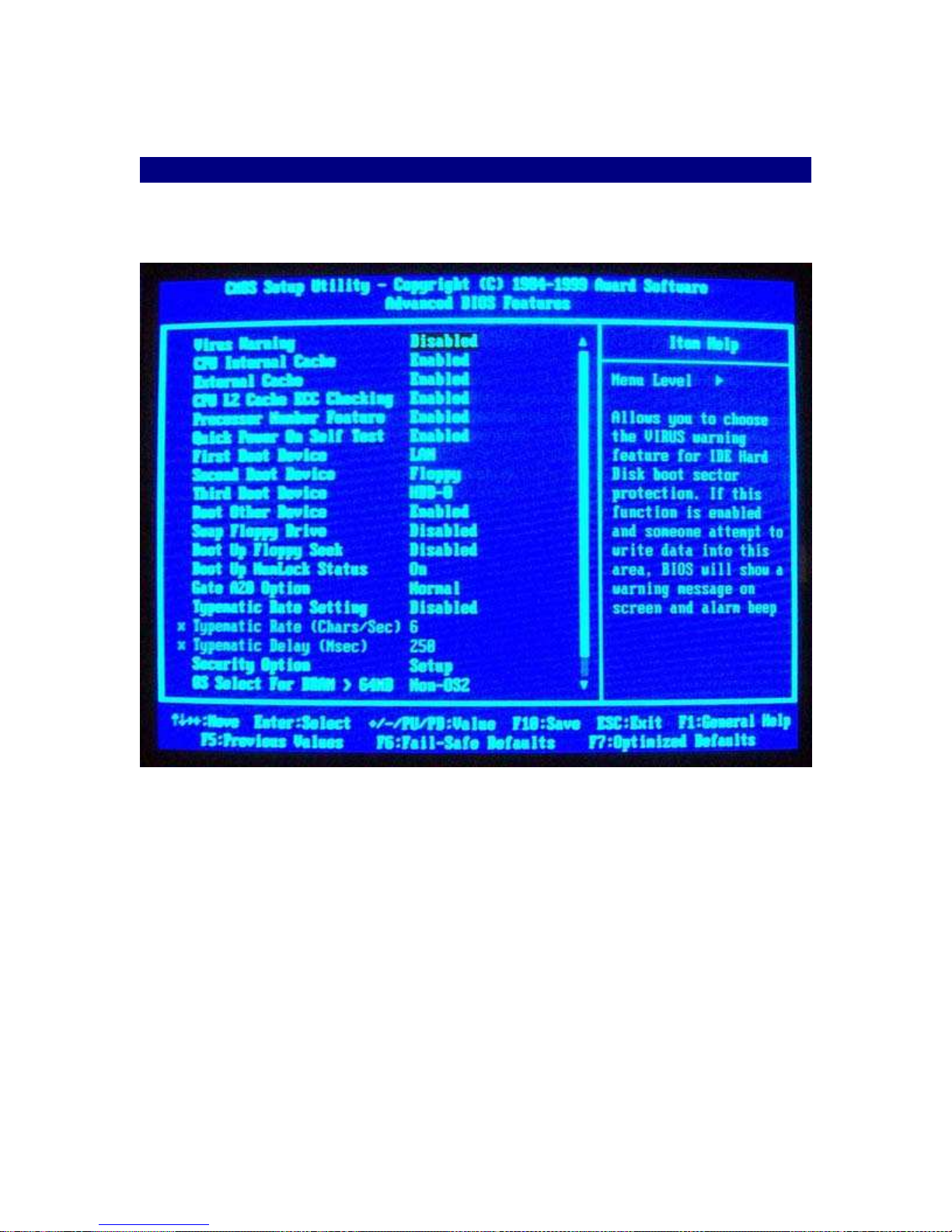
4.3 BIOS Features Setup
By choosing the BIOS FEATURES SETUP option from the INITIAL SETUP SCREEN menu, the
screen below is displayed. This sample screen contains the default values for the Pegasus.
Figure 4-3
28
Page 29
PEGASUS
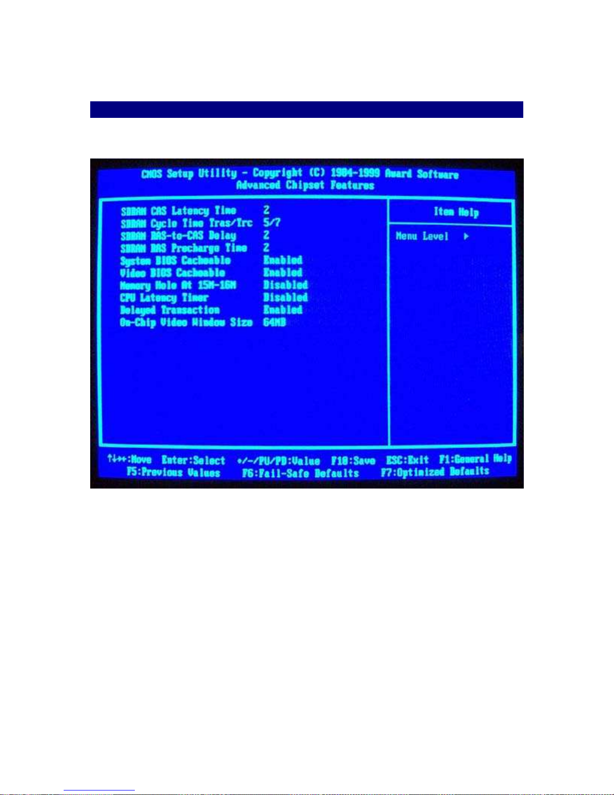
4.4 Chipset Features Setup
By choosing the CHIPSET FEATURES SETUP option from the INITIAL SETUP SCREEN menu,
the screen below is displayed. This sample screen contains the default values for the Pegasus.
Figure 4-4
29
Page 30
PEGASUS
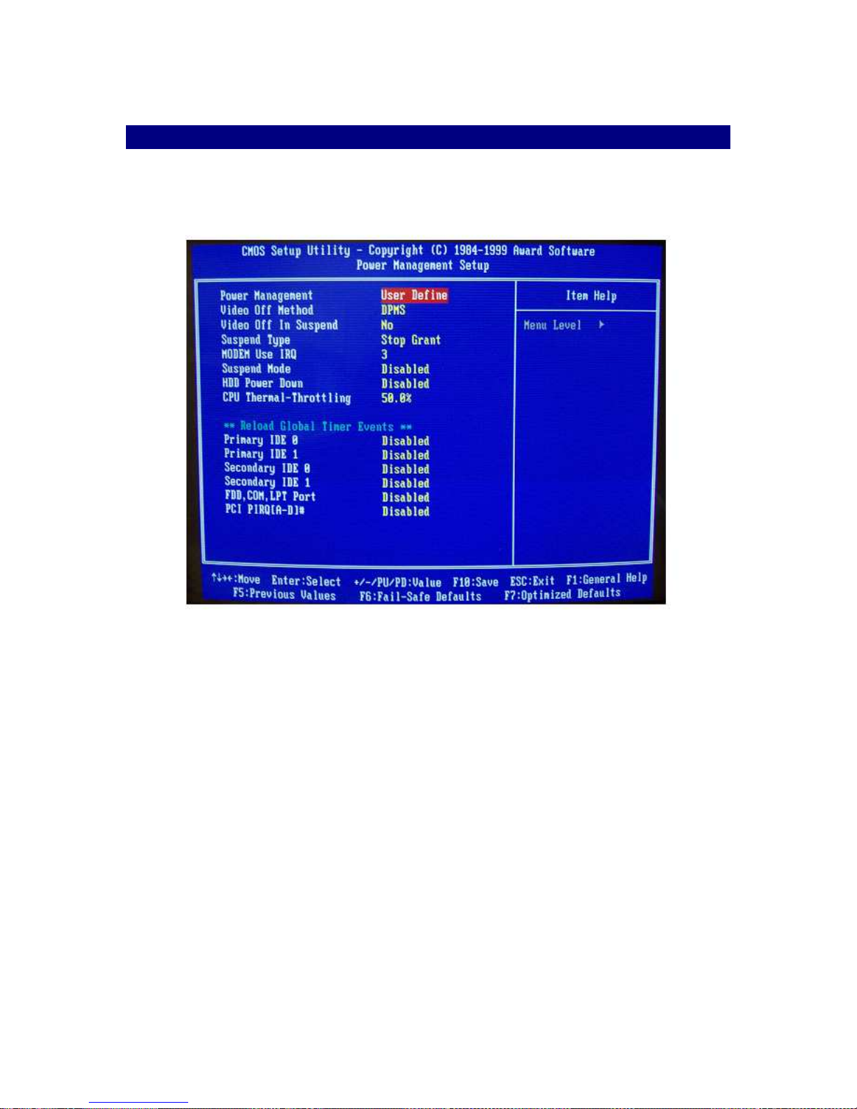
4.5 Power Management Setup
By choosing the POWER MANAGEMENT SETUP option from the INITIAL SETUP SCREEN
menu, the screen below is displayed. This sample screen contains the default values for the
Pegasus.
Figure 4-5
30
Page 31
PEGASUS
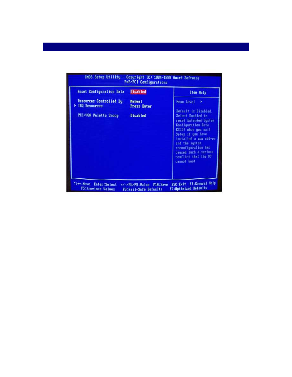
4.6 PnP/PCI Configuration Setup
By choosing the PnP/PCI CONFIGURATION option from the Initial Setup Screen menu, the
screen below is displayed. This sample screen contains the default values for the Pegasus.
Figure 4-6
31
Page 32
PEGASUS
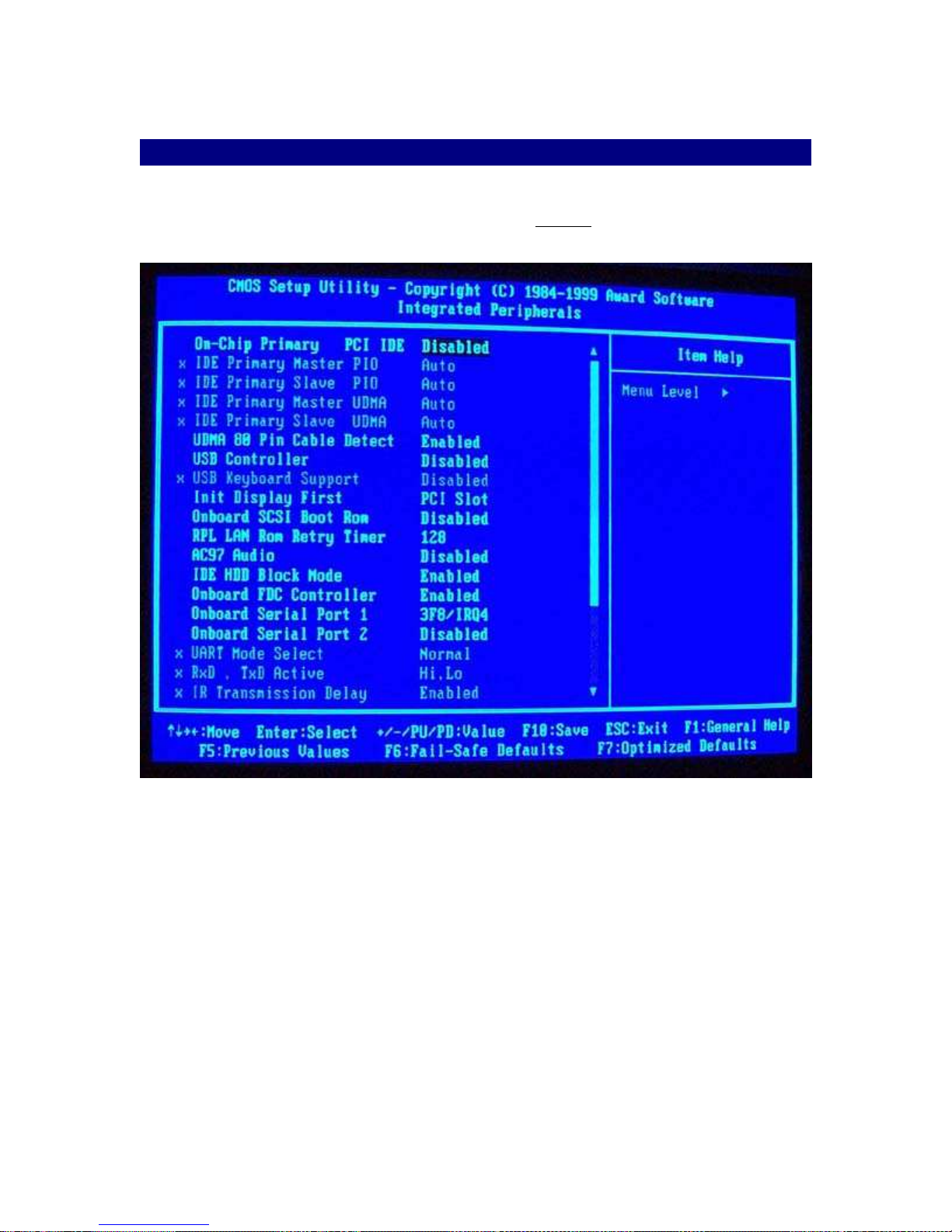
4.7 Integrated Peripherals Setup
By choosing the INTEGRATED PERIPHERALS option from the INITIAL SETUP SCREEN menu,
the screen below is displayed. This sample screen contains the default values for the Pegasus.
Use this page to change the “On-Chip Primary PCI IDE.” Enabled is required to use the onboard
UDMA-66 controller.
Figure 4-7
32
Page 33
PEGASUS
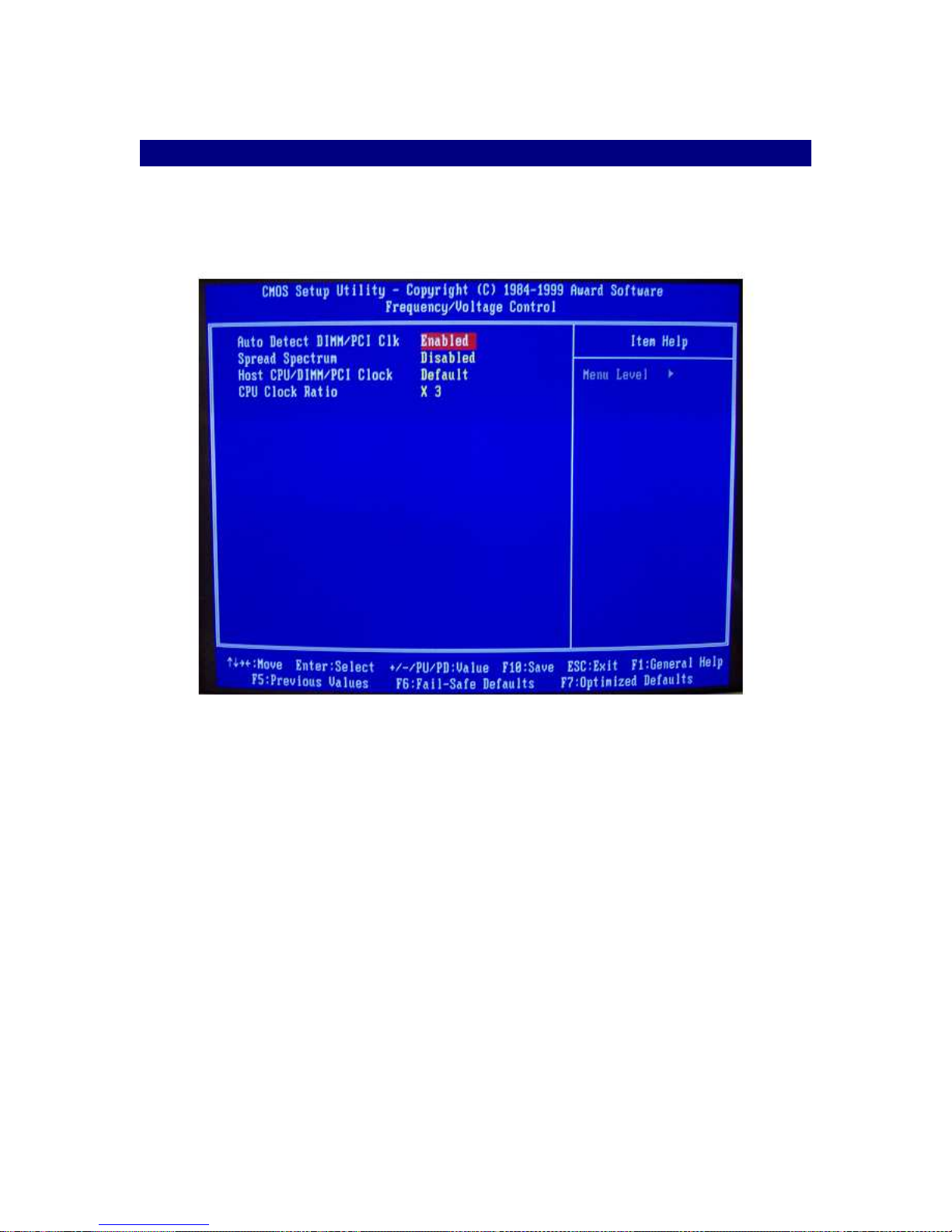
4.8 Frequency / Voltage Control
By choosing the FREQUENCY / VOLTAGE CONTROL option from the INITIAL SETUP SCREEN
menu, the screen below is displayed. This sample screen contains the default values for the
Pegasus.
Figure 4-8
33
Page 34
PEGASUS
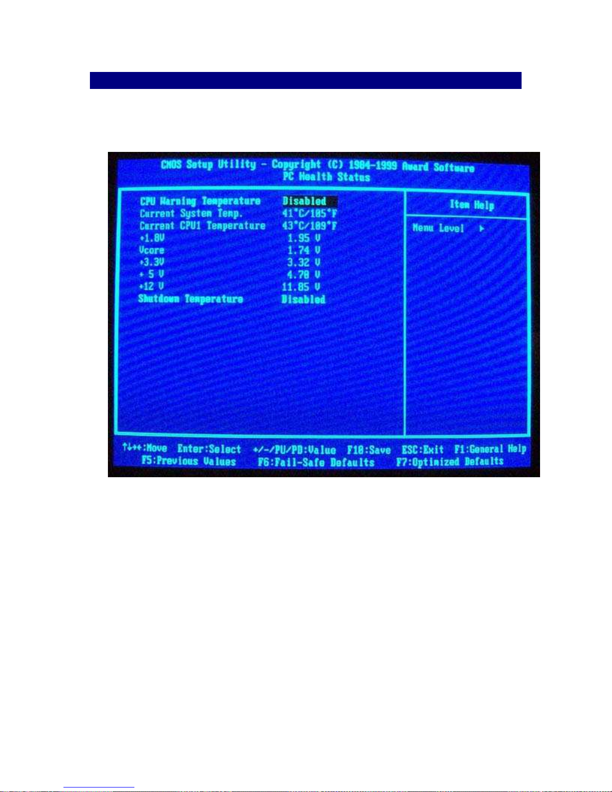
4.9 PC Health
By choosing the PC health option from the initial setup screen menu, the screen below is
displayed. This sample screen contains the default values for the Pegasus. Use this page to set
the CPU warning temperature and to set the shutdown temperature.
34
Page 35

PEGASUS
5.0 Programming the Watchdog Timer
The Pegasus is equipped with a watchdog timer that resets the CPU or generates an interrupt if
processing comes to a standstill for whatever reason. This feature ensures system reliability in
industrial standalone, or unmanned, environments.
In order to program the watchdog timer, you must write a program, which writes I/O port address
443 (hex). The output data is a value of time interval. The value range is from 01(hex) to 3E(hex),
and the related time interval is 1 sec. to 62 sec.
Data Time Interval
01 1 sec.
02 2 sec.
03 3 sec.
04 4 sec.
. .
. .
. .
3E 62 sec.
After the timer expires, your program must refresh the watchdog timer by rewriting the I/O port
443 (hex). When you want to disable the watchdog timer, your program should read I/O port 443
(hex).
35
Page 36

PEGASUS
6.0 Technical Support
For additional technical support, please contact your local FlexStar representative. Contact
information is listed below:
Flexstar Technology
47323 Warm Springs Boulevard
Fremont, CA 94539
(510) 440-0170 Fax (510) 440-0177
Email: [email protected]
[email protected]
www.flexstar.com
Japan, Korea, China & Thailand
PhaseMetrics
www.phasemetrics.com
Singapore & Malaysia
AutoStar
www.autostar.com.sg
36
Page 37

PEGASUS
BIOS Configuration.........................................................................................................................25
BIOS Features.............................................................................................................................................28
Chipset Features..........................................................................................................................................29
Entering Setup.............................................................................................................................................25
Frequency/Voltage Control.........................................................................................................................33
Integrated Peripherals.................................................................................................................................32
PnP/PCI Configuration...............................................................................................................................31
Power Management....................................................................................................................................30
Standard CMOS Setup................................................................................................................................27
Installation.......................................................................................................................................11
Audio Connector.........................................................................................................................................21
CD Line-In Connector................................................................................................................................21
CPU............................................................................................................................................................11
CPU Fan Connector....................................................................................................................................23
DIMM Memory..........................................................................................................................................11
DIMM Slot Connector................................................................................................................................23
Floppy Connector.......................................................................................................................................20
Front Panel Connector................................................................................................................................21
Hub Lock/Unlock.......................................................................................................................................14
IDE Disk Drive Connections......................................................................................................................16
IDE External Power Connector..................................................................................................................22
Internal Speaker..........................................................................................................................................14
IR Connector...............................................................................................................................................22
Locating Connectors...................................................................................................................................16
Locating Jumpers........................................................................................................................................12
PC104 +......................................................................................................................................................14
PCI Slot Connector.....................................................................................................................................23
Power Connector........................................................................................................................................17
Reserved J4.................................................................................................................................................14
Reserved J5.................................................................................................................................................14
Setting Jumpers...........................................................................................................................................13
Tri-State Buffer Control.............................................................................................................................14
Unpacking.......................................................................................................................................12, 14, 15
USB Connector...........................................................................................................................................22
PCI VIO & PCI PIN-A26 Select ..............................................................................................................15
SCSI Connector (Optional)........................................................................................................................17
Introduction........................................................................................................................................8
Software Configuration....................................................................................................................24
Remote Boot LAN Configuration...............................................................................................................24
SVGA Setup...............................................................................................................................................24
Technical Support...........................................................................................................................36
Watchdog Timer..............................................................................................................................35
Installation..........................................................................................................................................
10/100 Ethernet LAN Connector................................................................................................................20
COM-1 Connector......................................................................................................................................20
COM-2 Connector......................................................................................................................................20
GPIO Connector.........................................................................................................................................18
PS/2 Mouse & Keyboard Connector .........................................................................................................19
Parallel Port Connector .............................................................................................................................18
PC104 PLUS Connector ...........................................................................................................................19
VGA & Keyboard Connector....................................................................................................................19
37
 Loading...