

Flex Scada Flexs Q5, Flexs Q5 Pro User Manual
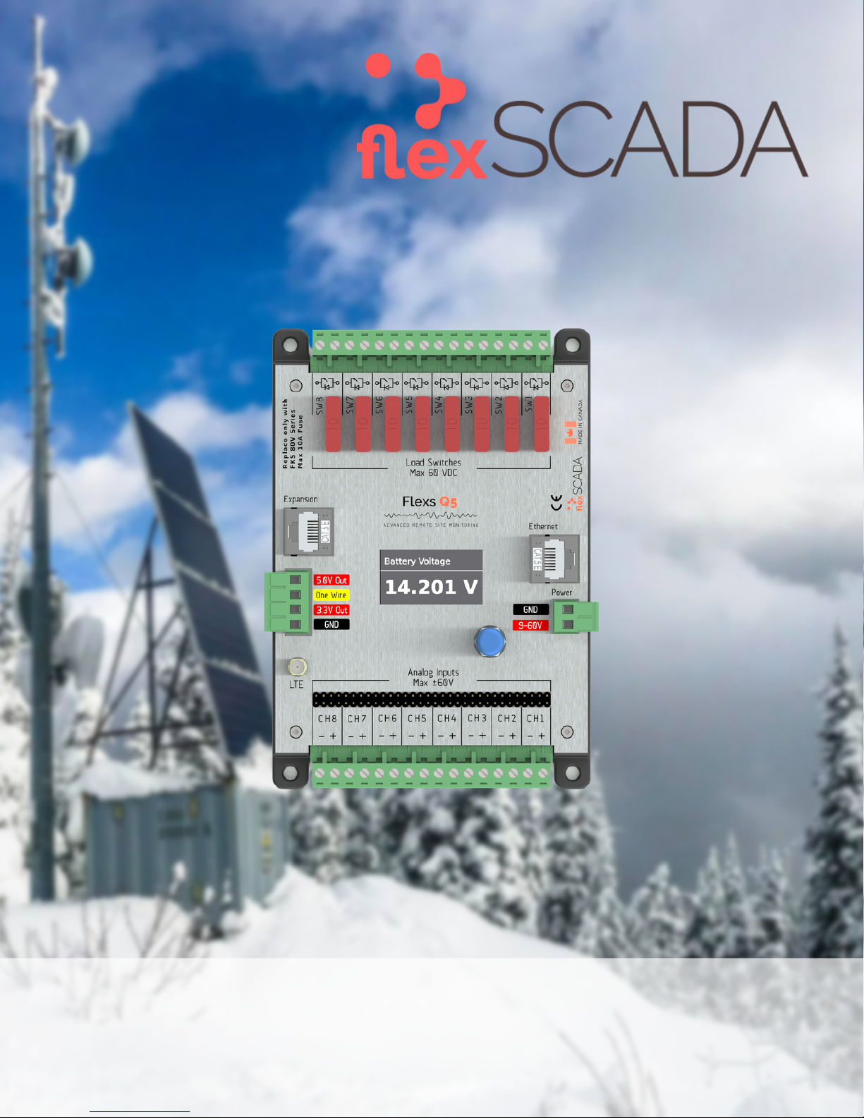
F l e x s Q 5 / Q 5 P r o
A D V A N C E D R E M O T E S I T E M O N I T O R I N G
R e v : 3 . 2 L a s t U p d a t e d : 2 0 1 9 / 0 1 / 2 1
U S E R G U I D E

T A B L E O F C O N T E N T S
G O T Q U E S T I O N S ?
Can't find what you're looking for?
We love hearing from our customers!
Please contact us with any questions.
C O N T A C T
+1 877.352.7398
support@flexscada.com
www.flexscada.com
P.O. Box 277
Lytton, B.C. V0K 1Z0
Canada
C O N T E N T S
Section 1.0: Hardware Specifications
Section 1.1: What's included
Section 1.2: Getting Started
Section 1.3: Web Interface Overview
Section 1.4: Main Menu
Section 1.5: Visualization Menu
Section 1.6: Input Graphing
Section 1.7: Input Oscilloscope
Section 1.8: Device Options Page
Section 1.9: Ping Probes Page
Section 1.10: Network Page
Section 2.0: Analog Inputs
Section 2.1: Voltage Inputs
Section 2.2: Current Inputs
Section 2.3: 1-wire sensors
Section 2.5: AC Power Metrics
Section 3.0: Relay Configuration
Section 4.0: Scripting
Section 5.0: SNMP
Section 6.0: Device Firmware Updater
Section 7.0: Device Interface
Section 8.0: Expansion Interfaces
Section 9.0: Warranty Terms
G L O S S A R Y
1-wire/one-wire - a sensor protocol developed by Dallas Semiconductors
A - Amps (Unit of Current)
AC - Alternating Current
AVG - Average
Bit - The smallest possible amount of data: 0 or 1
Bool or Boolean - true or false, usually represented with a single bit
Byte - 8 bits
CH - Channel
CT - Current Transformer
DC or VDC - Direct Current
DFU - Define Firmware Updater
DHCP - Dynamic Host Configuration Protocol
DNS/NS - Domain Name Service (server that converts names to IPs)
FET - MOSFET (Type of semiconductor switch)
FW - Firmware
Floating Point - Any non-whole number
HTTP - HyperText Transfer Protocol
HTTPS - Secure HyperText Transfer Protocol
HVD - High Voltage Disconnect
HW - Hardware
Hz - Hertz (Cycles per second)
I2C - Communication protocol
INS - Instantaneous Value
IP - Internet Protocol v4
IPv6 - Internet Protocol v6
IoT - Internet of Things
JSON - JavaScript Object Notation
kSPS - Thousand Samples Per Second
LAT/LNG - GPS Latitude/Longitude (Decimal Degrees Format)
LTE - 4G Cellular Service
LVD - Low Voltage Disconnect
MAC - Media Access Control
mA - Milliamps (1000th of an Amp)
mJ - Megajoules
MODBUS - Communication protocol used for Industrial PLC's
Mbps - Megabits Per Second
Ohms - Unit of Impedance
PF - Power Factor
PING or IMCP - Internet Control Message Protocol
PoE - Power Over Ethernet
RMS - Root Mean Square
SLAAC - IPv6 Stateless Address Autoconfiguration
SNMP - Simple Network Management Protocol
SW - Switch
Subnet/Netmask/NM - Refer to Internet Protocol
TCP - Transmission Control Protocol
THD - Total Harmonic Distortion
TX - Transmit
Typ - Typical
UART - TTL Level Serial
UID - Unique Identifier
V - Volts
VDC - Volts DC
VT - Voltage Transformer
W - Watt (Unit of Power)

1 . 0 - H a r d w a r e S p e c i f i c a t i o n s
P H Y S I C A L
Dimensions: 157 mm x 108 mm x 40 mm (Mounting Holes: 96 mm x 144 mm - 4 x 3mm)
Also mount with standard DIN Rail - Recommended DIN Rail space: 120 mm
Temperature Rating: –40 to 85°C (industrial rated components)
Environment: Max 95% relative humidity, non-condensing ( ETSI300-019-1.4 Standard )
Weight: 200g
P O W E R R E Q U I R E M E N T S
Voltage: 9 - 60 VDC (reverse polarity protected)
Power Consumption: 0.6 W @ 12V Typical (varies based on configuration)
A N A L O G I N P U T S
Analog Conversion: 24 bit; 0.05 mV @ ±60 V range; 0.004 mV precision @ ±5 V range
Voltage Range: ±60 V (fully differential, bi-polar) (0.5 MΩ. Imp)
Current Range: 0 - 25 mA (requires hardware jumper change)
L O A D S W I T C H E S
Max Voltage: 60 VDC
Max Current: 8 A Max Cont (100 A Surge <1 ms) (50% derating above 50° C)
Switch Type: Isolated solid state N-Channel FET /w fly-back protection
Fusing: ATO blade style fuse (replace only with fuses rated for correct voltage range)
Software Fuse: 500 mA to 5 A ***PRO ONLY***
Current Sensing: 0 to 5 A ***PRO ONLY***
R E G U L A T E D O U T P U T S
5.0 V output: 500 mA Max
3.3 V output: 500 mA Max (Typ 3.47V)
3.3 V Output /w LTE Module: 150 mA Max (Typ 3.47V)
E T H E R N E T
10/100 Mbps Operation
Long-Range 300 Meter at 10 Mbps
IEEE 802.3az Energy Efficient Ethernet
±15 kV IEC 61000-4-2 Level 4 ESD Protection
IEEE 802.3 Auto-Negotiation
IPv4: DHCP, Static; IPv6: SLAAC, DHCPv6, Static
Passive PoE: Pins 4, 5+; 7, 8- @ 9 to 56V
LTE SPECS ***LTE VERSION ONLY***
LTE CAT–M1/NB–IoT 3GPP release 13 LTE Adv. Pro
SMA Connector: SMA-Female
LTE Bands: 2, 3, 4, 5, 8, 12, 13, 20, 28
Modem: ublox SARA-R410M-02B
Certified by: FCC, ISED, PTCRB, NCC, RCM, RED,
AT&T, Telus, Telstra, Verizon, GITEKI 2
1 . 1 - W h a t ' s I n c l u d e d
1 x Flexs Q5
1 x DIN Rail Mounting Kit
1 x Product Manual
1. 2 - G e t t in g St a r t ed
This section provides a brief overview on how to connect to a FlexsQ5 for the first time.
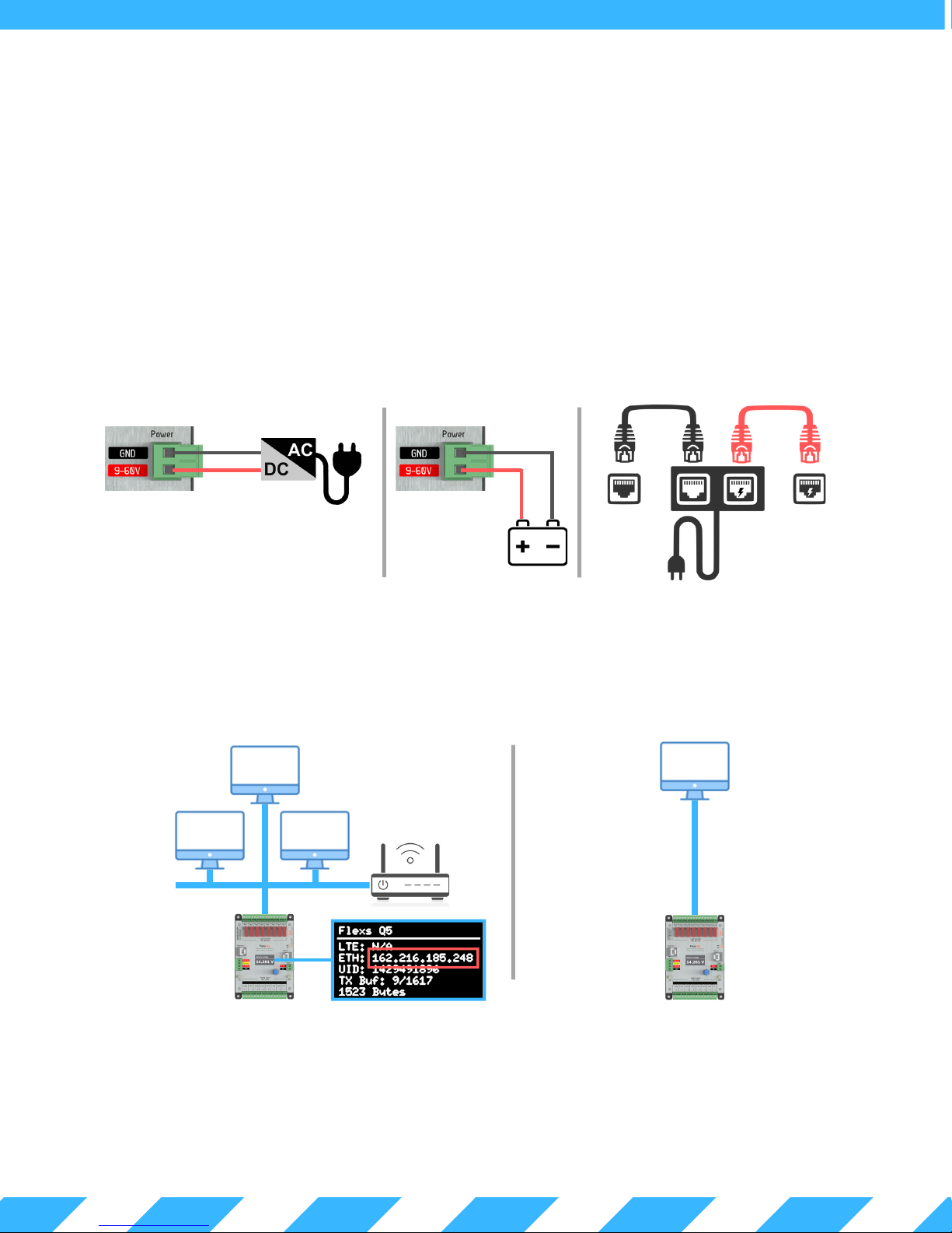
Attach the Q5 to a power source (9 to 60 VDC) using the two pin power terminal located beside the Ethernet port.
The Q5 can alternatively be powered via POE over the Ethernet port.
DO NOT POWER THIS DEVICE DIRECTLY FROM AN AC POWER SOURCE! DOING SO WILL VOID YOUR WARRANTY!
Powering with a Passive PoEPowering with a DC Power Supply Powering with a Battery
AC Power
Q5 Power Input
Once power is connected, the Q5 display will illuminate indicating that the Q5 has successfully started.
The Q5 will then search for a router on the network to get an IP address. If the Q5 fails to find a router within the first 10s
of bootup, it will fallback to standalone mode. In standalone mode, the Q5 will use the fallback IP (default 192.168.1.20).
Network Connected Mode
DC Power
Supply
Q5 Power Input
9 - 60 V Battery
PC Ethernet Q5 Ethernet
AC Power
Standalone Mode
24 V PoE
Connect using the IP assigned by your network.
This IP can be found on the Q5 display
(highlighted in red above)
Using Chrome, Firefox or Safari enter the device IP in the address bar to load the Q5's web interface.
The default password for the device is "flexscada".
IT IS HIGHLY RECOMMENDED TO CHANGE THIS PASSWORD WITH A SECURE PASSWORD TO AVOID
UNAUTHORIZED ACCESS TO THE DEVICE.
Connect using the following addresses:
http://192.168.1.20 OR with IPv6
http://[fe80::744]
Main Menu
(see sec. 1.4)
Configured
Analog Inputs
(see sec. 2.0)
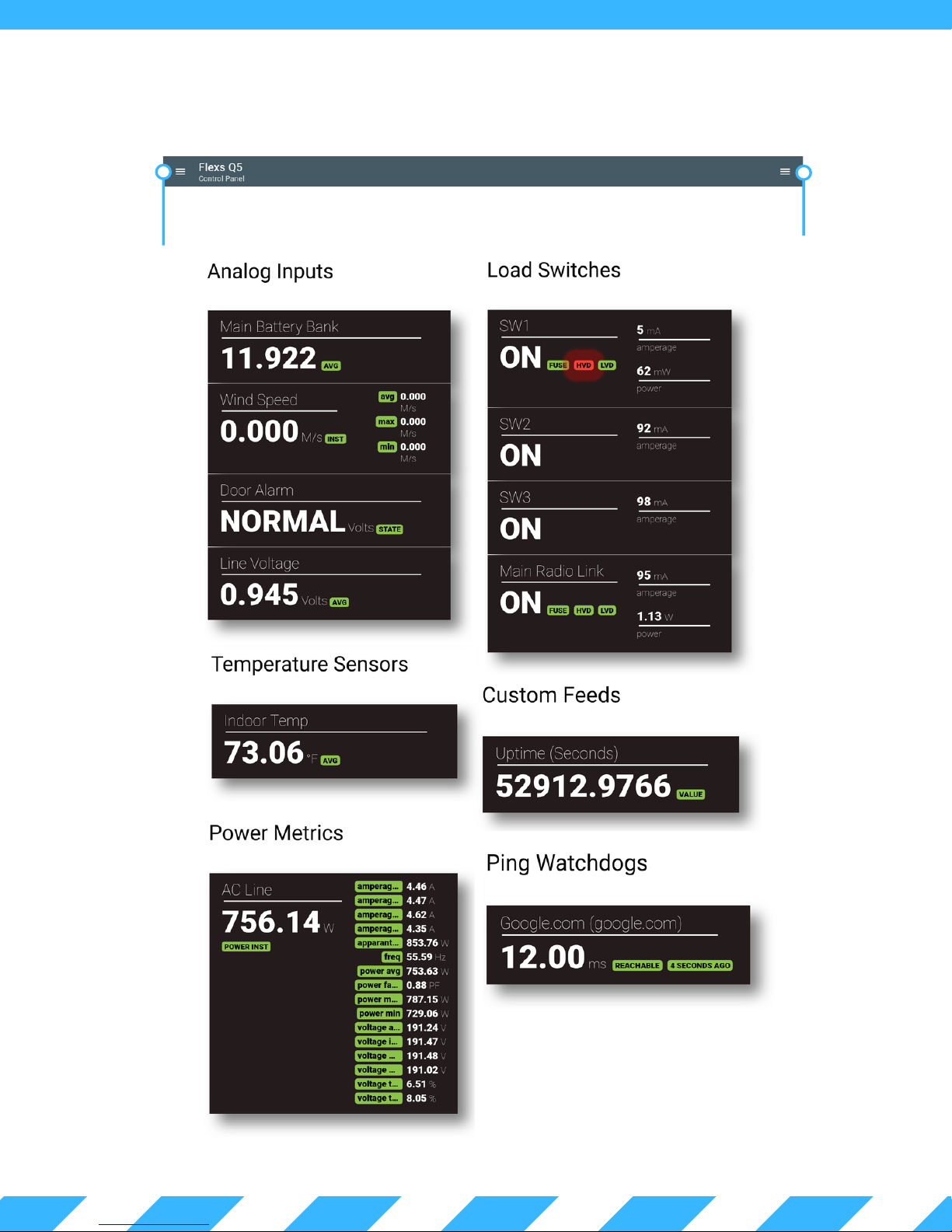
1 . 3 W e b I n t e r f a c e O v e r v i e w
Visualization Menu
(see sec. 1.5)
Load Control
(see sec. 3.0)
Adopted 1Wire Temp
Sensors
(see sec. 2.1)
Computed
Power Metrics
(see sec. 2.5)
Registers set from
custom scripting
(see sec. 4.0)
Ping Watchdog
Status (see sec. 1.9)
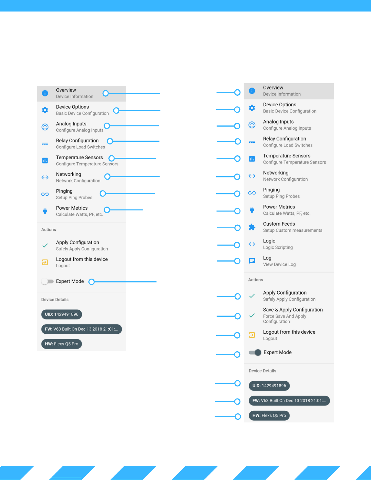
1 . 4 - M a i n M e n u
Expert Mode - Disabled Expert Mode - Enabled
Dashboard Page
(see sec. 1.3)
Device Options Page
(see sec. 1.8)
Analog Inputs Page
(see sec. 2.0)
Load Outputs Page
(see sec. 3.0)
1-Wire Sensors Page
(see sec. 2.3)
Networking Page
(see sec. 1.10)
Ping Watchdog Page
(see sec. 1.9)
Calculated Power Metrics
(see sec. 2.5)
Custom Feeds (see sec. 4.0)
Custom Scripts (see sec. 4.0)
System Log Page
Expert Mode (disabled)
Safely Apply Settings
(user must confirm after saving.)
Save and apply settings
(without confirm option)
Logout
Expert Mode (enabled)
Unique Device ID (UID)
Firmware Version
Hardware Type
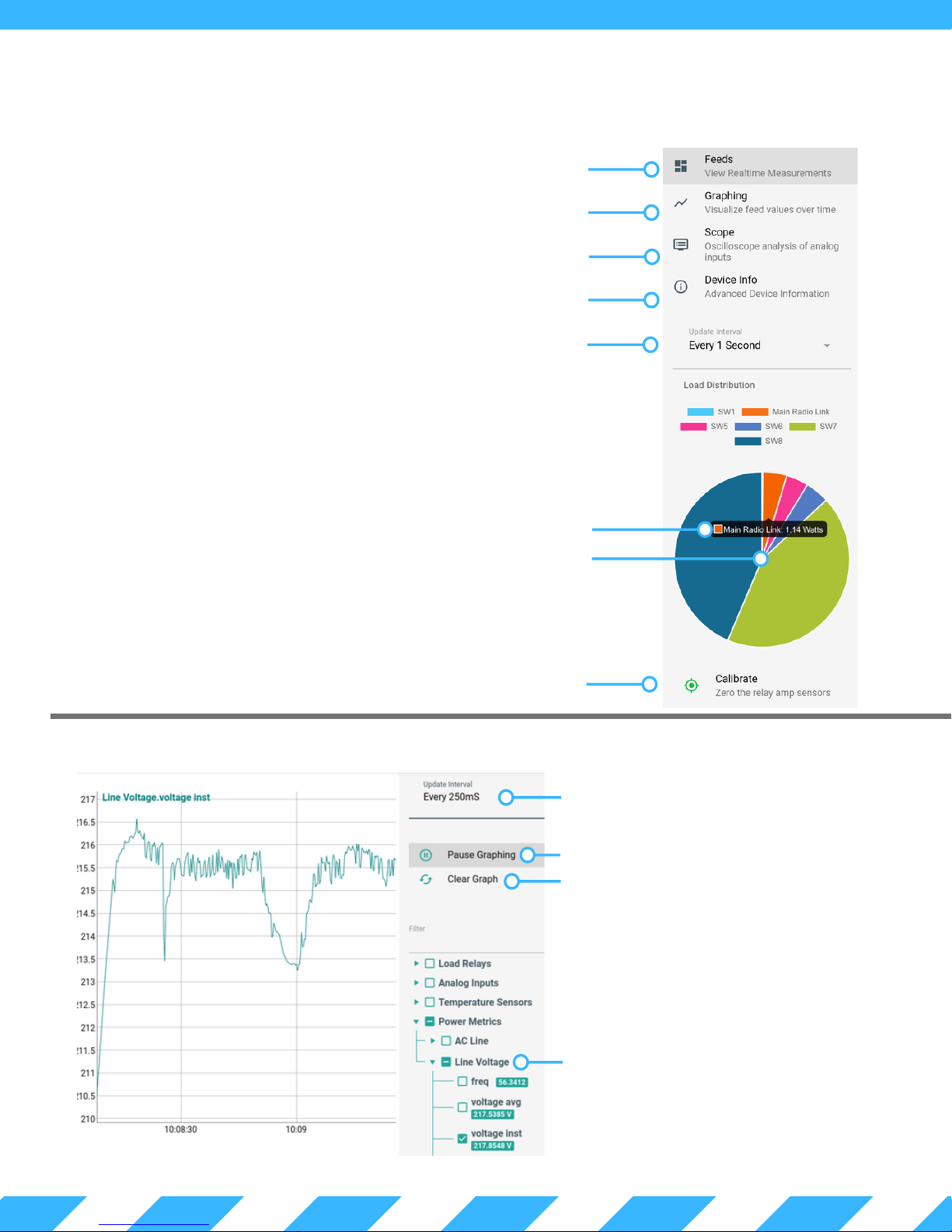
1 . 5 - V i s u a l i s a t i o n M e n u
Dashboard Page (see sec. 1.3)
Input Graphing Page (see sec. 1.6)
Input Oscilloscope Page (see sec. 1.7)
Advanced Device Info
Data Update Interval
View Load Watts (PRO ONLY)
Load Distribution (PRO ONLY)
Manually Zero Load Sensors (PRO ONLY)
1 . 6 - I n p u t G r a p h i n g P a g e
Data Update Interval
Pause/Start Data Collection
Clear Graph Of All Data
The graphing tool is used to view short
term trends, such as current or voltage
readings. The Update Interval range
can be configured from 100ms to 1
minute.
Select Data Metrics to Graph
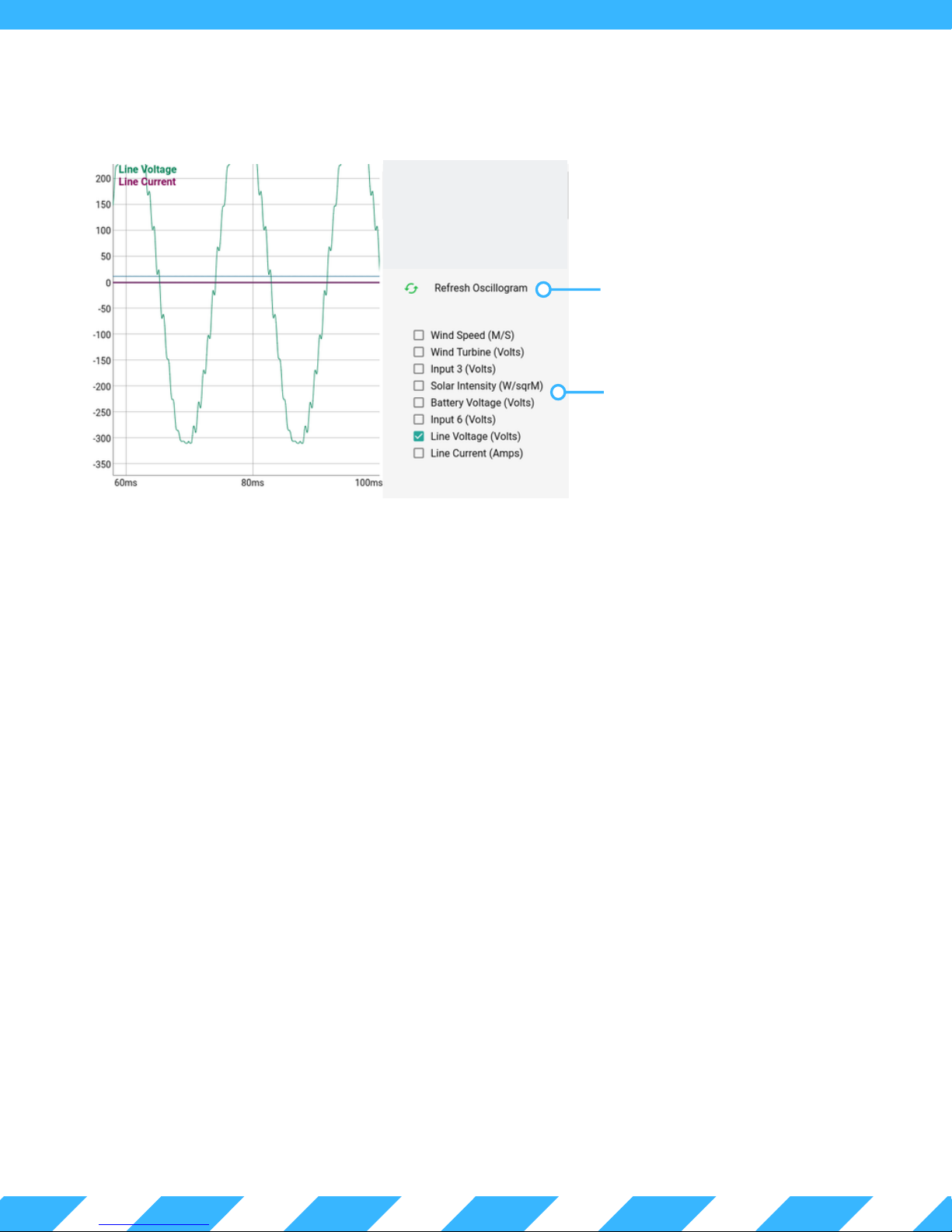
1 . 7 - I n p u t O s c i l l o s c o p e P a g e
Sample Data and
Regenerate Graph
Select Data Channels
to Display
The oscilloscope tool provides a close-up look at how "clean" your power source is.
When the refresh button is clicked, 2,000 simultaneous readings are taken across all 8 channels and then displayed
in the web interface. The sample rate of the Q5 is 8,000 samples/second (i.e. 8 samples taken each millisecond).
 Loading...