


Power Genius XL
User Manual
rev 10.
▲ Index 1/23

Table of Contents
0. Important notice.....................................................................................................................................3
1. Unpacking..............................................................................................................................................5
1.1. Front Panel.....................................................................................................................................5
1.2. Back Panel......................................................................................................................................6
1.3. BCD/PTP connector pinout............................................................................................................8
2. Using with Radios..................................................................................................................................9
2.1. FlexRadio Series 6000....................................................................................................................9
2.2. Yaesu...............................................................................................................................................9
2.3. Elecraft...........................................................................................................................................9
Other radios.........................................................................................................................................10
3. Turning ON..........................................................................................................................................10
3.1. Front Display overview................................................................................................................13
3.1.1. STBY/OPER.........................................................................................................................13
3.1.2. Band verification..................................................................................................................14
3.1.3. Vdd and Id verification.........................................................................................................14
3.1.5. Temperature..........................................................................................................................15
3.1.6. Power....................................................................................................................................15
3.1.7. SWR......................................................................................................................................15
3.2. Backlight modes...........................................................................................................................16
3.2.1. Stand By Mode – Yellow backlight......................................................................................16
3.2.2. Operate Mode – Green backlight..........................................................................................17
3.2.3. TX Mode – Red backlight....................................................................................................17
4.1. MEffA overview...........................................................................................................................18
5. Power derating with temperature increase...........................................................................................18
5.1. Power derating overview..............................................................................................................18
5.2. Reducing maximum voltage with temprature..............................................................................18
6. Alarms..................................................................................................................................................19
6.1. High SWR alarm..........................................................................................................................19
6.2. Id alarm.........................................................................................................................................19
6.3. Fan failure alarm..........................................................................................................................20
6.4. Power supply failure alarm...........................................................................................................20
6.5. Forbidden band.............................................................................................................................21
6.6. Internal error.................................................................................................................................21
▲ Index 2/23

FCC STATEMENT
CAUTION: The users manual or instruction manual for an intentional or unintentional radiator
shall caution the user that changes or modifications not expressly approved by the party
responsible for compliance could void the user's authority to operate the equipment.”
Note: This equipment has been tested and found to comply with the limits for a Class B digital
device, pursuant to part 15 of the FCC Rules. These limits are designed to provide
reasonable protection against harmful interference in a residential installation. This equipment
generates, uses and can radiate radio frequency energy and, if not installed and used in
accordance with the instructions, may cause harmful interference to radio communications.
However, there is no guarantee that interference will not occur in a particular installation. If
this equipment does cause harmful interference to radio or television reception, which can be
determined by turning the equipment off and on, the user is encouraged to try to correct the
interference by one or more of the following measures:
- Reorient or relocate the receiving antenna.
- Increase the separation between the equipment and receiver.
- Connect the equipment into an outlet on a circuit different from that to which the receiver is
connected.
- Consult the dealer or an experienced radio/TV technician for help.
0. Important notice
This amplifier has been configured to operate in your country according to your nation's
regulations. It will operate on frequencies which are not allowed for public use. You are
required to have a valid amateur radio license of an appropriate class from your government
to have the privileges to operate on amateur radio frequencies.
Except those actions which have been described in this user manual, no other manipulations
to the amplifier are allowed. The unit must only be opened and/or serviced by a qualified
technician.
▲ Index 3/23
WARNING!

If you have any questions due to misunderstanding, translation errors and alike, please
contact the appropriate party for further information.
Radio frequency energy (RF) from transmitters can interact with some electronic devices,
such as cardiac peacemakers and defibrillators.. Please refer to the implanted peacemaker or
defibrillator manufacturer's instructions with respect to precautions to be taken in the vicinity
of a radio amateur transmitter. If any interaction or interference with a peacemaker or
implanted defibrillator is suspected, STOP transmitting immediately.
! - WARNING!
▲- Caution
i – Information
! – This unit is NOT A TOY. It must not be handled by children nor placed/operated
within reach of children.
! – Do not leave packing material for this unit unattended. It may be harmful to children
if misused.
! – This unit contains small parts that could be a choking hazard to small children. Do
not leave accessories unattended.
! – Do not operate this unit in potentially explosive environments.
! – Never attempt to insert wires or any tools into the interior of this unit during
operation. This may cause fire or electric shock.
! – This unit must only be operated with the electrical power described in the User
Manual. Doing otherwise may cause a fire, injury or electrical shock.
! – Never connect or disconnect antennas while in TRANSMIT mode. This may cause
electrical shock or RF burns to your skin and damage to the unit.
! – This unit generates Radio Frequency (RF) energy. Use caution and observe proper
safety practices regarding your system configuration. When attached to an antenna,
this amplifier is capable of generating RF electromagnetic field which require
evaluation according to your national law to provide any necessary isolation or
▲ Index 4/23

protection required, with respect to human exposure!
▲- This unit must only be opened and/or serviced by a qualified technician. Opening
the unit may void the manufacturer's warranty.
▲- Do not operate this unit in areas of extreme humidity.
▲- Avoid operating this amplifier in direct sunlight or other areas of extreme heat,
excessive vibration, or mechanical force.
▲- If this unit is intended for use in commercial applications, special safety regulations
and cautions may apply to prevent accidents.
▲- If any defect, abnormal result, or other observations occur that are not covered by
this User Manual; immediately cease operation and contact the manufacturer or local
distributor for operational advice or repair of the unit.
i – No other physical modification of this amplifier is allowed. Any other use or
modification (including software changes that affect operational characteristics) will
void the manufacturer's warranty.
i – Ensure proper ventilation around the amplifier; This includes 30 cm clearance in
front and back.
i – Please study the complete User Manual. This document contains important
information regarding the safe operation of this unit. If you have any questions, please
contact the manufacturer or local distributor for further information.
▲ Index 5/23

1. Unpacking
To be written when we know more about packaging.
1.1. Front Panel
The front panel is designed to intuitive and uncluttered. It consists of two elements:
1 Standby / Operate button.
2 RGB LED Backlight
3 LCD Touchscreen Display
Pressing the STBY/OPER button toggles between standby and operate modes.
The LCD Touchscreen Display shows all the important data for monitoring during operation.
The RGB LED backlight shows operation states:
• Stand By mode is indicated by a yellow color.
• Operate mode is indicated by a green color.
• Transmitting is indicated by a red color.
• Firmware Upgrade mode is indicated by a magenta color.
▲ Index 6/23

More details on the display elements and different states in follow separate chapters on these
subjects.
1.2. Back Panel
The connectors are logically divided into two groups, A and B, for respective radios.
▲ Index 7/23

1 AC Power input: standard 120V or 220V AC used to power the amplifier.
2 RF Precorrector B output: -60dBc output signal, for connecting to a radio
precorrector. (if radio has one)
3 PTT output B: standard RCA connector. It outputs GND as a PTT signal. Can be
configured to +12V by internal jumper. Pins are isolated with optocouplers.
4 RF output B: standard PL259 type connector for connecting your antenna.
5 RF output A: standard PL259 type connector for connecting your antenna.
6 RF input A: standard PL259 type connector for connecting your transceiver.
7 RF input B: standard PL259 type connector for connecting your transceiver.
8 PTT input B: standard RCA connector. It expects GND as a PTT signal. Can be
configured to +12V by internal jumper.
9 Chassis Ground: #8 Thumb screw
10 RF Precorrector A output: -60dBc output signal, for connecting to a radio
precorrector. (if radio has one)
11 PTT output A: standard RCA connector. It outputs GND as a PTT signal. Can be
configured to +12V by internal jumper. Pins are isolated with optocouplers.
12 Ethernet connector – Not in use. Reserved for a future upgrade.
13 CI-V input B: standard 3.5mm stereo connector for ICOM radio band data.
Pins are isolated with optocouplers.
14 BCD/PTP input B: standard female DB15 connector for radio band data.
Pins are isolated with optocouplers.
15 CAT input B: standard male DB9 type connector for radio CAT connection.
Pins are isolated with optocouplers.
16 CI-V input A: standard 3.5mm stereo connector for ICOM radio band data.
Pins are isolated with optocouplers.
17 CAT input A: standard male DB9 type connector for radio CAT connection.
Pins are isolated with optocouplers.
18 BCD/PTP input A: standard female DB15 connector for radio band data.
Pins are isolated with optocouplers.
19 PTT input A: standard RCA connector. It expects GND as a PTT signal. Can be
configured to +12V by internal jumper. Pins are isolated with optocouplers.
20 Power Switch: Turn the amplifier ON or OFF.
▲ Index 8/23

1.3. BCD/PTP connector pinout
PTP input – Uses PTP signal (+12V) to select
the proper filter. Pins are isolated with
optocouplers.
Pin 1 Filter for 1,8 to 2 MHz
Pin 2 Filter for 3.5 to 4 MHz
Pin 3 Filter for 5 to 7.5 MHz
Pin 4 or 5 Filter for 10 to 14.5 MHz
Pin 7 or 8 or 9 Filter for 18 to 29.5 MHz
Pin 10 Filter for 50 to 52 MHz
BCD input – Uses BCD signal (+12V) signal
to select the proper filter. Pins are isolated
with optocouplers.
BCD inputs are designed for a direct
connection to a band decoder used by radios
such as YAESU and Elecraft.
Filter No.
Band
Frequency
Band A
Band B
Band C
Band D
Hex Code
1 2 3 4 4 5 5 5 5 6 NA
160m 80m 40m 30m 20m 17m 15m 12m 10m 6m None
1.8 3.5 7 10 14 18 21 24 28 50 NA
H
L
L
L
H
L
L
L
H
H
L
L
L
L
H
L
1 2 3 4 5 6 7 8 9 A 0
H
H
L
L
H
H
L
L
H
H
H
L
L
L
L
H
H
H
L
L
L
H
L
H
L
L
L
L
▲ Index 9/23
2. Using with Radios
This chapter covers connecting your Power Genius XL with various popular radios.
2.1. FlexRadio Series 6000
Not possible in the current version. Will be released in the future as an upgrade.
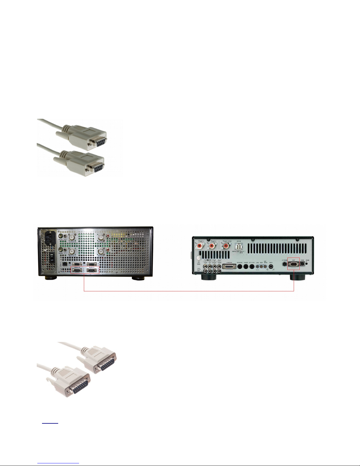
2.2. Yaesu
Yaesu radios are connected using the CAT (RS232) port on the
amplifier.
Use straight female to female DB9 cable.
Connection is the same for all standard Yaesu radio models.
All pins on on the CAT connector are isolated by optocouplers.
You can use either Radio A or Radio B CAT connector on your PG XL.
2.3. Elecraft
▲ Index 10/23
Elecraft radios are connected to the BCD (band decoder) port
on the PG XL.
Use straight male to male DB15 cable.
Connection is the same for all standard Elecraft radio models.

All pins on on the BCD connector are isolated by optocouplers.
You can use either Radio A or Radio B BCD connector on your PG XL.
Other radios
Universally, you can get band data from radios in one of two ways:
A) Getting data from BCD / PTP protocol
Connect your radio or band decoder to the BCD/PTP port on the amplifier.
This connection requires no additional configuration and works automatically.
The BCD/PTP connection has the highest priority, and will ignore other connections if
they exist.
B) Getting data from CAT protocol
Connect your radio to the CAT (RS232) port on the amplifier.
Configure the CAT protocol details using the PG XL Windows app.
3. Turning ON
Place your Power Genius XL on a flat stable surface.
Make sure your Power Genius XL amplifier has at least 30cm of space in front and in the back
to insure adequate cooling.
Follow these steps before powering your Power Genius XL:
▲ Index 11/23

1) Connect the radio to the RF INPUT on the PG XL. (A or B port)
2) Connect the antenna to the corresponding RF OUTPUT on PG XL.
3) Connect the radios PTT to the corresponding PTT input connector on PG XL.
4) Connect the radios band data to PG XL. This can be done in one of 3 ways, depending
on the exact model of the radio you will be using:
(a) Using a band decoder (BCD or PTP protocol, depending on the radio you are
using).
This connection requires no additional configuration and works automatically.
The BCD/PTP connection has the highest priority, and will ignore other connections
if they exist.
(b) Using RS232 for connecting radios CAT information. (Kenwood, Yaesu, Elecraft,
ICOM 7800)
Configure the CAT protocol details using the PG XL Windows app.
(c) CI-V connection for older ICOM radios.
Configure the CI-V protocol details using the PG XL Windows app.
After connecting everything use the supplied power cable to connect PG XL to the power
outlet.
Upon powering up, the display will show the loading screen, and the device will go to stand by
mode.
Before transmitting:
1) Press the OPERATE button front panel.
This will activate the operate mode, and measuring bars will appear on the display. You
can also see the OPERATE label in the bottom left corner of the screen.
▲ Index 12/23

2) Verify the band data is being read correctly by looking at the main display on PG XL.
The band data is marked in red on the picture below.
If everything is ok, you start using the amplifier.
▲ Index 13/23

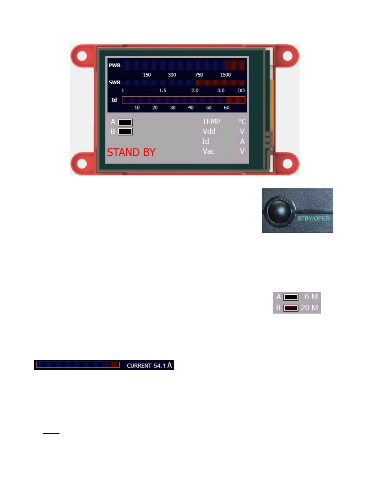
3.1. Front Display overview
3.1.1. STBY/OPER
Pressing the STBY/OPER button will toggle between stand by and operate modes. \
The difference between these two modes is that:
• In STBY mode the PTT connection line is disabled.
• In OPER mode the PTT connection line is enabled.
The “STAND BY” label in the lower left corner of the display indicates
the current mode is stand by.
Yellow LED backlight is another indication that you are in stand by
mode.
▲ Index 14/23
Press the button again to go into operate mode.
The “OPERATE” label in the lower left corner of the display indicates
the amplifier is in operate mode.
Green LED backlight is another indication that you are in operate
mode.
3.1.2. Band verification
The red LED will glow on the currently active radio.
You can always see the selected bands for radio A and B.
3.1.3. Vdd and Id verification
The bar ranges from 0 to 60 amps.
Normal VDD ranges are from 41V to 51V.
▲ Index 15/23

VDD is automatically controlled depending on temperature control and efficiency.
3.1.5. Temperature
You can read your current operating temperature here.
Fans are controlled automatically by the firmware.
Optimal operation is below 60 °C.
Above 60 °C firmware will begin decreasing power to protect the amplifier from permanent
damage.
If temperature exceeds 85° C the amplifier will go into alarm mode to prevent transmitting
before the temperature drops.
3.1.6. Power
The entire power bar range is from 0 to 2000W.
The red section is above 1500W.
3.1.7. SWR
Maximum allowed working SWR is 1:3.
Firmware will enable the power derating algorithm when SWR is between 1:1.5 and 1:3.
Above 1:3 SWR the amplifier will go to alarm mode, preventing transmitting.
▲ Index 16/23

3.2. Backlight modes
3.2.1. Stand By Mode – Yellow backlight
The yellow backlight indicates the amplifier is in STAND BY mode.
In order to activate the operate mode, click the STBY/OPER button on
the front panel.
▲ Index 17/23

3.2.2. Operate Mode – Green backlight
The green backlight indicates the amplifier is in OPERATE mode.
Tapping the green operate button on the touch screen display will activate stand by mode.
3.2.3. TX Mode – Red backlight
The red backlight indicates the amplifier is in TX mode.
▲ Index 18/23

4.1. MEffA overview
MEffATM stands for Maximum Efficiency Algorithm.
For single tone modes (CW, RTTY), MEffA sets dynamic real time output device drain voltage and
current yielding maximum efficiency for output power in real time reducing heat dissipation for
efficiency up to 75%.
Up to 65% head dissipation reduction efficiency with excellent IMD characteristics for SSB.
5. Power derating with temperature increase
5.1. Power derating overview
APC regulates output power in case of difficulties in amplifier operation. When high VSWR is
detected, APC proportionately reduces output power to safe level allowing continued operation
When VSWR exceeds high limit, APC switches amp to STBY (RF input bypassed directly to output)
mode.
When APC detects increased heat sink temperature, it will reduce output power only if the MEffATM
system can’t contain it within allowed limits; when the amplifier cools to a safe 60 degrees C, APC will
return amp back to full power
5.2. Reducing maximum voltage with temprature
The firmware constantly monitors Vdc levels on the LDMOS.
In case of very high temperatures the firmware will reduce power and with that heat
dissipation and protect the unit.
When the temperature returns to normal, the power levels are turned back up..3. Monitoring
▲ Index 19/23

6. Alarms
6.1. High SWR alarm
Release PTT to dismiss the alarm message.
6.2. Id alarm
▲ Index 20/23

6.3. Fan failure alarm
6.4. Power supply failure alarm
▲ Index 21/23

6.5. Forbidden band
Amplifier operation is disabled in the range of 26 to 28MHz.
PG XL has a built in frequency counter. In the case the drive signal is within 26 to 28MHz
range, operation is blocked by disabling PTT and inhibiting the RF amplifier section.
6.6. Internal error
▲ Index 22/23

In case the display module looses communication with the main processor. Try rebooting the
amplifier.
▲ Index 23/23
 Loading...