

Power Genius XL
User Guide
FlexRadio is a registered trademark and SmartSDR is a trademark of FlexRadio.
All other brands or names are trademarks of their respective owners.
Power Genius XL Firmware Version 3.4.16
Power Genius XL Utility Version 2.2.10
27 August 2020
Copyright 2020 FlexRadio Systems. All Rights Reserved.

Contents
1 Important Notice ............................................................................................................................. 4
2 Features of the Power Genius XL ..................................................................................................... 6
2.1 Front Panel ............................................................................................................................... 6
2.2 Back Panel ................................................................................................................................. 7
2.3 PTB/BCD Connector Pinout ....................................................................................................... 9
3 Power Genius XL Setup, Configuration, and Testing ....................................................................... 10
3.1 Unpacking and Setup .............................................................................................................. 10
3.2 Connecting the Power Genius XL Windows Utility .................................................................. 12
3.3 Basic Configuration ................................................................................................................. 14
3.3.1 Network Tab: Set a Custom Device Name ........................................................................ 14
3.3.2 Network Tab: Configuring the Network ........................................................................... 14
3.3.3 Network Tab: Testing Network Configuration .................................................................. 15
3.3.4 FlexRadio Tab: Configuring for a FLEX-6000 Series Transceiver. ....................................... 17
3.4 Advanced Configuration ......................................................................................................... 19
3.4.1 Configuring the Power Genius XL .................................................................................... 19
3.4.2 Required RF Output Delay (TX Delay) .............................................................................. 20
3.4.3 Interfacing with Other Exciters ........................................................................................ 22
3.5 Testing .................................................................................................................................... 33
4 Operating the Power Genius XL ..................................................................................................... 35
4.1 Changing Standby and Operate Modes................................................................................... 35
4.1.1 Standby Mode ................................................................................................................. 35
4.1.2 Operate Mode ................................................................................................................. 36
4.2 Setting Amplifier Bias Class ..................................................................................................... 36
4.2.1 Amplifier Bias Class Modes .............................................................................................. 37
4.3 Transmitting ............................................................................................................................ 38
4.3.1 Power Meter (PWR) ......................................................................................................... 38
4.3.2 SWR meter ...................................................................................................................... 39
4.3.3 Id Meter ........................................................................................................................... 39
4.3.4 PTT and Band Data .......................................................................................................... 39
4.3.5 Temperature and Voltage ................................................................................................ 40
4.3.6 Additional Information .................................................................................................... 40
4.4 Status LED (Backlight) ............................................................................................................. 41
4.4.1 Standby Mode – Yellow backlight .................................................................................... 41
Page 2 of 61
Copyright 2020 FlexRadio. All Rights Reserved. August 27, 2020 (FW:3.4.16 Utility:2.2.10)

4.4.2 Operate Mode – Green backlight .................................................................................... 41
4.4.3 Transmitting – Red backlight ............................................................................................ 42
4.4.4 Firmware Upgrade in Progress– Magenta backlight ........................................................ 42
4.5 120 VAC Operations ................................................................................................................ 43
5 Maximum Efficiency Algorithm (MEffA™) ...................................................................................... 44
6 Automatic Power Control (APC) ..................................................................................................... 45
7 Harmonic Load ............................................................................................................................... 46
8 Thermal Management (Cooling) .................................................................................................... 47
8.1 Power Supply Unit (PSU) Fans ................................................................................................. 47
8.2 Power Amplifier (PA) Fans ....................................................................................................... 47
8.3 Harmonic Load and Filter Compartment Fan .......................................................................... 47
9 The Power Genius XL Windows Utility ........................................................................................... 48
9.1 Windows Utility Front Panel Display ....................................................................................... 48
9.2 Standby Operate Mode ........................................................................................................... 49
9.3 Active Fan Profile .................................................................................................................... 49
9.4 MEffA Indicator ....................................................................................................................... 49
9.5 Amplifier Configuration Dialog ............................................................................................... 49
9.5.1 Network Tab .................................................................................................................... 50
9.5.2 CAT/CI-V Tab .................................................................................................................... 51
9.5.3 FlexRadio Tab ................................................................................................................... 52
9.5.4 Other Tab ......................................................................................................................... 53
9.6 Usage Chart ............................................................................................................................ 54
10 Firmware Upgrade Procedure ........................................................................................................ 55
11 Factory Reset the Power Genius XL ................................................................................................ 57
12 Alarms ............................................................................................................................................ 57
13 Specifications ................................................................................................................................. 58
14 FCC Statement ............................................................................................................................... 58
15 Appendix ........................................................................................................................................ 59
15.1 Installing the Power Genius XL Utility .................................................................................. 59
Page 3 of 61
Copyright 2020 FlexRadio. All Rights Reserved. August 27, 2020 (FW:3.4.16 Utility:2.2.10)

1 Important Notice
WARNING!
This Radio Frequency (RF) power amplifier is designed to operate on frequencies designated
for amateur radio service. You are required to have a valid amateur radio license to operate
on these frequencies.
Please operate this amplifier, only by following the instructions in the quick start guide and this user guide. The
unit must only be opened or serviced by a qualified technician.
RF energy from transmitters can interact with some electronic devices, such as cardiac pacemakers and
defibrillators. Please refer to the pacemaker or defibrillator manufacturer's instructions concerning the
precautions to be taken near an amateur radio transmitter. If any interaction or interference with a pacemaker
or defibrillator is suspected, STOP transmitting immediately.
! - WARNING!
▲- Caution
i – Information
! – This unit is NOT A TOY. It must not be handled by children nor placed/operated within reach of
children.
! – Do not leave packing material for this unit unattended. It may be harmful to children if misused.
! – This unit contains small parts that could be a choking hazard to small children. Do not leave
accessories unattended.
! – Do not operate this unit in potentially explosive environments.
! – Never attempt to insert wires or any tools into the interior of this unit during operation. This may
cause fire, electric shock, or death!
! – This unit must only be operated with the electrical power described in this User Guide. Doing
otherwise may cause a fire, injury, or electrical shock.
! – Never connect or disconnect antennas while in TRANSMIT mode. This may cause electrical shock
or RF burns and damage to the unit.
! – This unit generates high levels of Radio Frequency (RF) energy. Use caution and observe proper
safety practices regarding your system configuration. When attached to an antenna, this amplifier
can generate RF electromagnetic fields which require evaluation according to your national law to
provide any necessary isolation or protection required, concerning human exposure.
Page 4 of 61
Copyright 2020 FlexRadio. All Rights Reserved. August 27, 2020 (FW:3.4.16 Utility:2.2.10)

▲- This unit must only be opened and serviced by a qualified technician. Opening the unit may void
the manufacturer's warranty.
▲- Do not operate this unit in areas of extreme humidity.
▲- Avoid operating this amplifier in direct sunlight or other areas of extreme heat, excessive
vibration, or mechanical force.
▲- If this unit is intended for use in ICAS commercial applications, special safety regulations and
cautions may apply to prevent accidents.
▲- If any defect, abnormal result, or other observations occur that are not covered by this User
Guide, immediately cease operation and contact FlexRadio Support or local distributor for
operational advice or repair of the unit.
i – No physical modification of this amplifier is allowed. Any other use or modification (including
software changes that affect operational characteristics) will void the manufacturer's warranty.
i – Ensure proper ventilation around the amplifier; This includes 30 cm (12 inches) clearance in front
and back.
i – Please study the complete User Guide. This document contains important information regarding
the safe operation of this unit. If you have any questions, please contact the manufacturer or local
distributor for details.
Page 5 of 61
Copyright 2020 FlexRadio. All Rights Reserved. August 27, 2020 (FW:3.4.16 Utility:2.2.10)
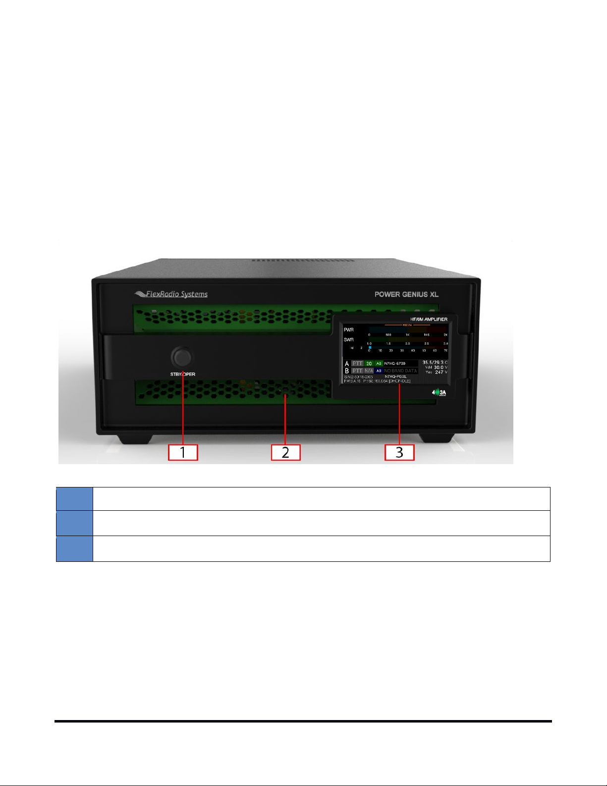
2 Features of the Power Genius XL
1
Standby / Operate button
2
RGB LED Backlight
3
LCD Touchscreen Display
• Full legal power on all HF bands and 6M in all modes. 1500W ICAS with headroom for 2000W
• Unique Maximum Efficiency Algorithm (MEffA™) for efficiencies up to 75%
• Duplexed filters maximize harmonic suppression and efficiency
• Fully SO2R capable – 70dB nominal isolation between exciter inputs
• Automatic Power Control (APC) for ultra-fast SWR protection
• Remote control with desktop application in LAN or WAN environments
2.1 Front Panel
Designed to be easy to use, the front panel is easy to understand and intuitive. It consists of three elements:
Pressing the STBY/OPER button toggles the amplifier between STANDBY and O P ERATE modes. The LCD
Touchscreen Display shows all the essential data for monitoring the amplifier while in operation. See Section
4.3 for details.
Copyright 2020 FlexRadio. All Rights Reserved. August 27, 2020 (FW:3.4.16 Utility:2.2.10)
Page 6 of 61

2.2 Back Panel
The back-panel connectors are logically divided into two groups, the A port connectors, and B port connectors.
The amplifier will amplify the signal on the A input and output it on the A output, or it will amplify the signal on
the B input and output it on the B output. The A and B sections of the amplifier can be controlled
independently by two radios. Separate A and B keying inputs (Push-To-Tal k , P T T, inputs) are provided as well as
separate band data inputs. Either of the A or B sections can be keyed at any one time, but they cannot be
keyed simultaneously.
Please refer to the table below.
Page 7 of 61
Copyright 2020 FlexRadio. All Rights Reserved. August 27, 2020 (FW:3.4.16 Utility:2.2.10)

1
AC Power input: 90-250V AC, 50/60 Hz
2
RF Adaptive predistortion A output: BNC female connector, -60dBc output signal, for
connecting to radio A's adaptive predistortion input.
3
RF Adaptive predistortion B output: BNC female connector, -60dBc output signal, for
connecting to radio B's adaptive predistortion input.
4
RF Output B: SO239 connector for connecting an antenna
5
RF Output A: SO239 connector for connecting an antenna
6
CAT Input B: Optoisolated male DB9 connector for radio B CAT command input.
7
RF Drive B: SO239 connector for connecting radio B
8
RF Drive A: SO239 connector for connecting radio A
9
Power Switch: Switches input power ON or OFF
10
PTT Output A: Optoisolated female RCA connector. The center pin is grounded when section
See Required RF Output Delay (TX Delay) for usage details.
11
PTT Input A: Optoisolated female RCA connector. Ground the center pin to shield to engage
See Required RF Output Delay (TX Delay) for usage details.
12
CAT Input A: Optoisolated male DB9 connector for radio A CAT command input
13
BCD/PTB Input A: Optoisolated DE-15 female connector for radio A band data
14
CI-V Input A: Optoisolated 3.5mm female connector for ICOM radio A band data
15
BCD/PTB Input B: Optoisolated DE-15 female connector for radio B band data
16
CI-V Input B: Optoisolated 3.5mm female connector for ICOM radio B band data
17
PTT Output B: Optoisolated female RCA connector. The center pin is grounded when section
See Required RF Output Delay (TX Delay) for usage details.
18
PTT Input B: Optoisolated female RCA connector. Ground the center pin to key the B section
See Required RF Output Delay (TX Delay) for usage details.
19
Ethernet connection: RJ45 Local Area Network Ethernet connection
A of the amplifier is keyed and ready to accept RF drive.
PTT for the A section of the amplifier.
B of the amplifier is keyed and ready to accept RF drive.
of the amplifier.
Page 8 of 61
Copyright 2020 FlexRadio. All Rights Reserved. August 27, 2020 (FW:3.4.16 Utility:2.2.10)
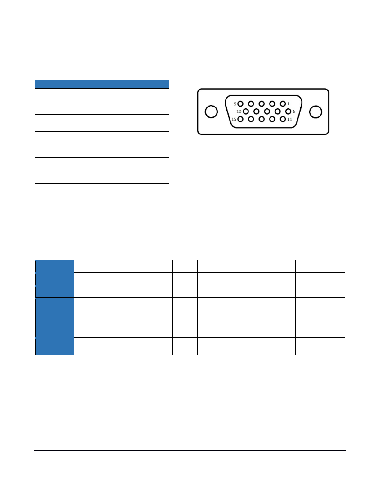
2.3 PTB/BCD Connector Pinout
Pin
Band
Frequency
Filter
1
160m
1.8 – 2.0 MHz
1 2 80m
3.5 – 4.0 MHz
2 3 40m
7.0 – 7.3 MHz
3 4 30m
10.10 – 10.15 MHz
4 5 20m
14.00 – 14.35 MHz
4 6 17m
18.068 – 18.168 MHz
5 7 15m
21.00 – 21.45 MHz
5 8 12m
24.89 – 24.99 MHz
5 9 10m
28.0 – 29.7 MHz
5
10
6m
50.0 – 54.0 MHz
6
15 Signal Ground
Filter
1 2 3 4 4 5 5 5 5 6 NA
Band
160m
80m
40m
30m
20m
17m
15m
12m
10m
6m
None
Frequency
1.8
3.5 7 10
14
18
21
24
28
50
NA
Pin 11
H
L
L
L
H
L
L
L
H
L
L
L
H
L
L
H
H
H
L
H
L
L
Hex Value
1 2 3 4 5 6 7 8 9 A 0
PTB input – A 5 to 15 volt DC signal applied to one of the pins described in the following table selects a band
and the appropriate filter. The pins are optoisolated. Pin 15 is the signal ground.
i – The 60-meter band cannot be selected with this method.
BCD input – A 4 bit BCD signal (5 to 15 volt DC) selects a band and its filter. The pins are optoisolated. Pin 15 is
the signal ground.
The BCD inputs are designed to be driven by a direct connection to a band decoder output provided by radios
such as Yaesu and Elecraft.
Pin 12
Pin 13
Pin 14
L
L
H
L
H
L
L
H
L
H
H
H
H
H
L
L
L
L
H
L
L
L
i – The 60-meter band cannot be selected with this method.
Filters – The amplifier engages output filters using a BCD value; the table above shows which filter is selected
for each value.
Copyright 2020 FlexRadio. All Rights Reserved. August 27, 2020 (FW:3.4.16 Utility:2.2.10)
Page 9 of 61

3 Power Genius XL Setup, Configuration, and Testing
3.1 Unpacking and Setup
The following accessories and materials are included with your Power Genius XL amplifier. Carefully remove the
amplifier from its shipping container, unpack, and identify the items listed below:
• One (1) Power Genius XL amplifier
• One (1) 2.4m (8 ft.) AC power cord with C13 connector and pigtails
• One (1) 2m (6 ft.) Ethernet cable
• One (1) Power Genius XL Quick Start Guide
Place your Power Genius XL on a flat, stable surface. Make sure the amplifier has at least 30cm (12 inches) of
open space in front and back to ensure adequate cooling. Follow these steps and reference the diagram to
connect your Power Genius XL:
1. Connect the transceiver antenna output to the Port A RF Drive socket on the PG XL.
2. Connect the antenna to the Port A RF Output socket.
3. Connect the supplied Ethernet cable from the RJ45 socket on the amplifier's back panel to a similar
socket on your Local Area Network's router or switch.
4. Apply a plug to the power cable, appropriate to your local electrical environment. Connect the cable to
the AC power source
amplifier will accept 90 to 250 volts AC, 50 or 60 Hz. If powered by less than 208 volts, it will operate at
a reduced maximum output power level.
1
and plug the C13 connector into the power socket on the back panel. The
5. Turn the amplifier on using the power switch on the back panel.
1
A dedicated 15-amp service with the proper circuit breaker wired per local, state or country codes or regulations.
Page 10 of 61
Copyright 2020 FlexRadio. All Rights Reserved. August 27, 2020 (FW:3.4.16 Utility:2.2.10)
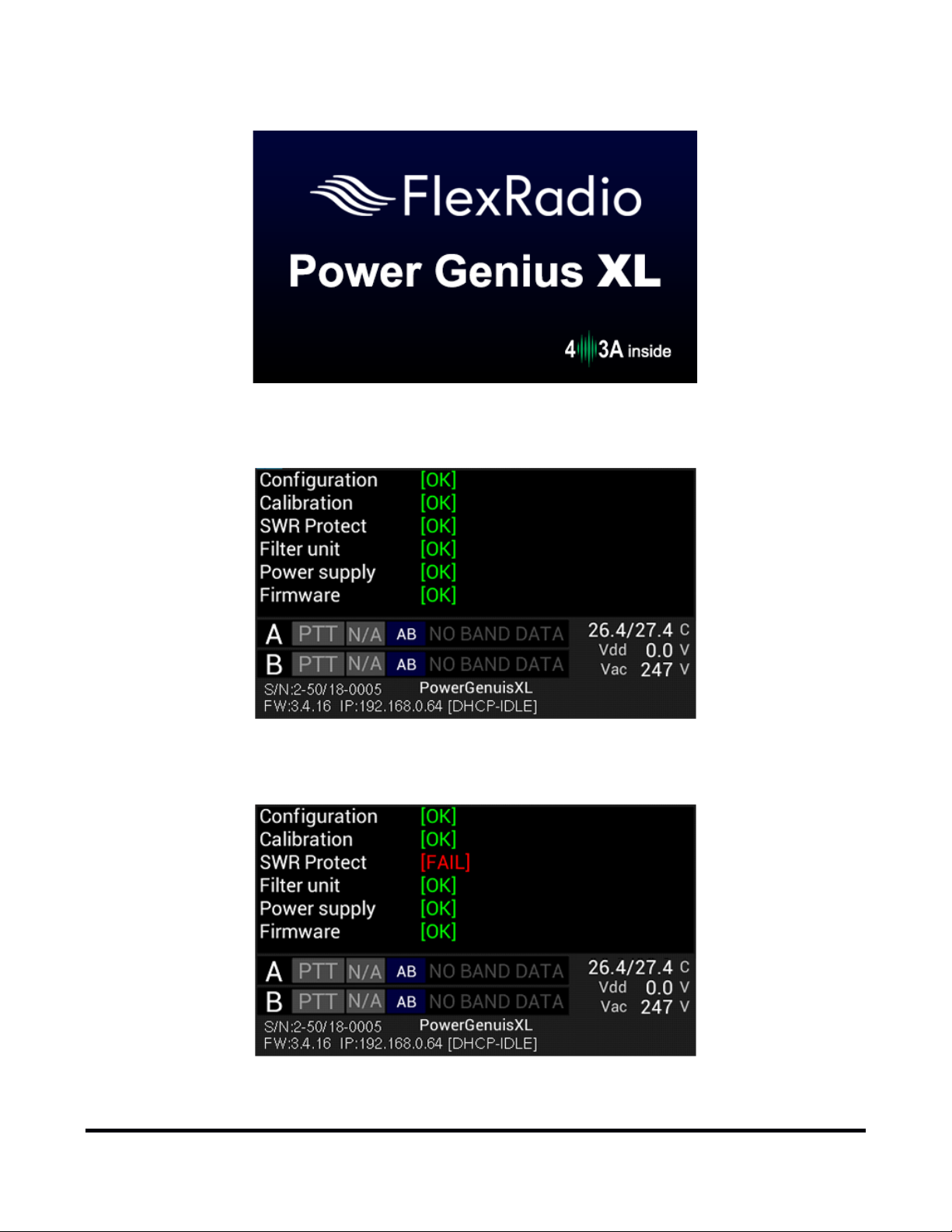
During power-up, the display will briefly show a splash screen similar to the following:
The amplifier will immediately conduct a power-on self-test (POST). The results of each test are displayed on
the front panel. If any tests fail, the amplifier cannot be operated and will not advance into standby mode.
If any POST test fails, an alarm message will be displayed. Contact FlexRadio Support for assistance. There are
no user-serviceable components inside the amplifier.
Page 11 of 61
Copyright 2020 FlexRadio. All Rights Reserved. August 27, 2020 (FW:3.4.16 Utility:2.2.10)
After the test sequence, the amplifier will query your network DHCP service for an available IP address and
automatically configure the network settings. If a DHCP service is not available or does not respond, the
amplifier will self-assign a Link-Local IP Address following the RFC-3927
i – If the displayed IP Address begins with 169.254, then the amplifier is using a Link-Local IP Address.
Depending on the configuration of your Local Area Network (LAN), this may indicate a network problem or
prevent further setup. Contact FlexRadio Support for assistance.
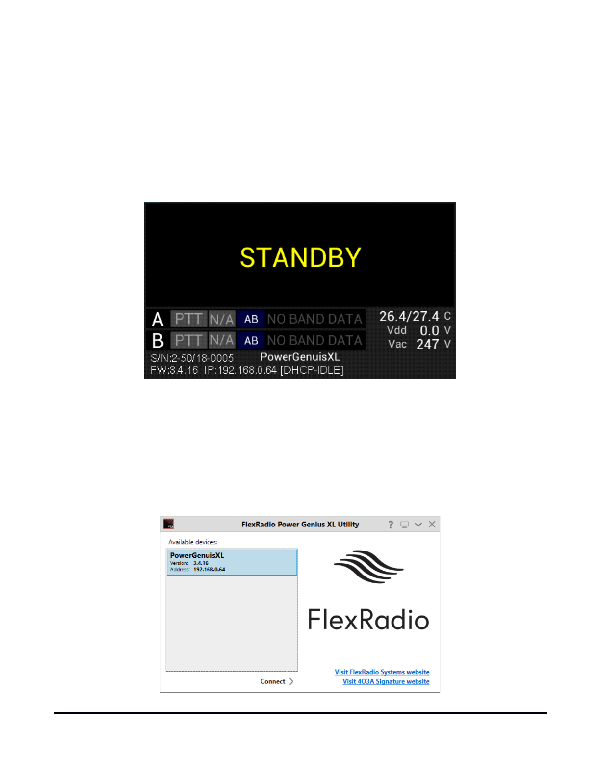
When the power-on-self-test completes and resolves an IP address, the amplifier will enter STAN D BY mode and
announce its presence on your Local Area Network. The Power Genius XL will always display the IP address.
specification.
3.2 Connecting the Power Genius XL Windows Utility
The Power Genius XL amplifier must be configured to work with the transceiver or transceivers that will drive it.
The basic configuration of the amplifier is accomplished using the Power Genius XL Utility. To install the utility,
please reference Installing the Power Genius XL Utility in the appendix.
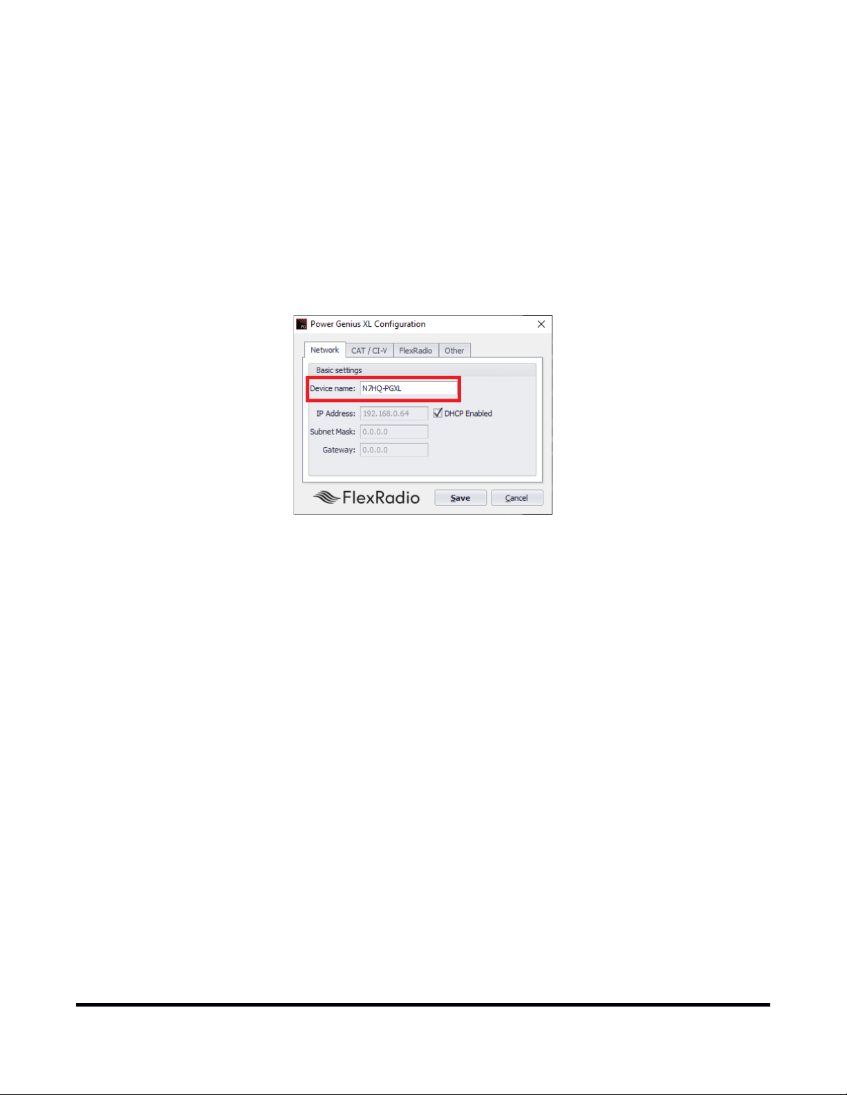
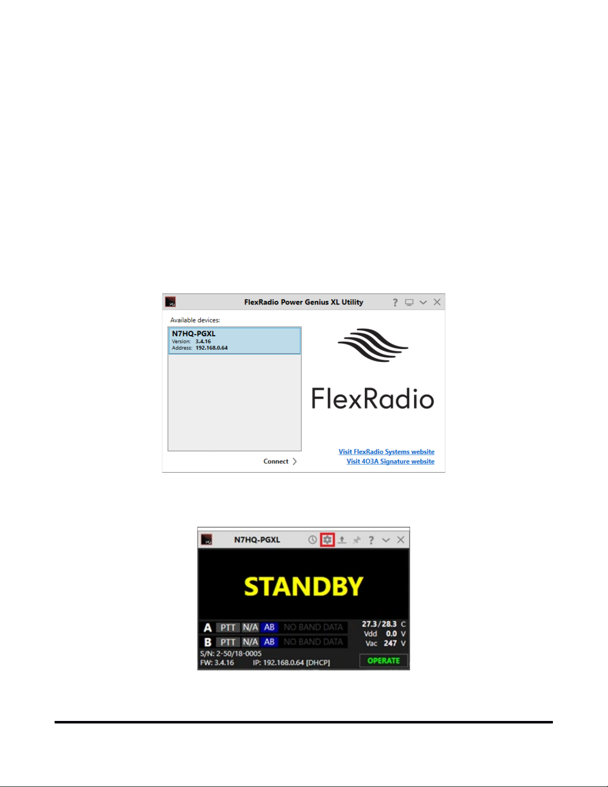
Start the Power Genius XL Utility program. It will automatically discover your Power Genius XL amplifier, and
you should see something similar to this:
Page 12 of 61
Copyright 2020 FlexRadio. All Rights Reserved. August 27, 2020 (FW:3.4.16 Utility:2.2.10)

If you do not see your Power Genius XL in the Available devices list, please:
• Double-check your network connections and cables.
• Ensure the Power Genius XL is powered up, and an IP address is displayed on the front panel.
• Check that your Firewall is configured to allow the Power Genius XL utility to communicate over your
network.
• Check that your PC and Power Genius XL share the same logical network (the IP address of your PC and
the Power Genius XL should be similar, though not identical).
If you still have trouble, please submit a HelpDesk ticket for assistance.
Click on your amplifier to select it, then click on the Connect button.
Once connected, an amplifier status screen will appear, similar to the image below. Click on the configuration
settings button (outlined in red) to open the configuration settings for the amplifier.
Page 13 of 61
Copyright 2020 FlexRadio. All Rights Reserved. August 27, 2020 (FW:3.4.16 Utility:2.2.10)
3.3 Basic Configuration
Please complete the following steps to configure your Power Genius XL.
3.3.1 Network Tab: Set a Custom Device Name
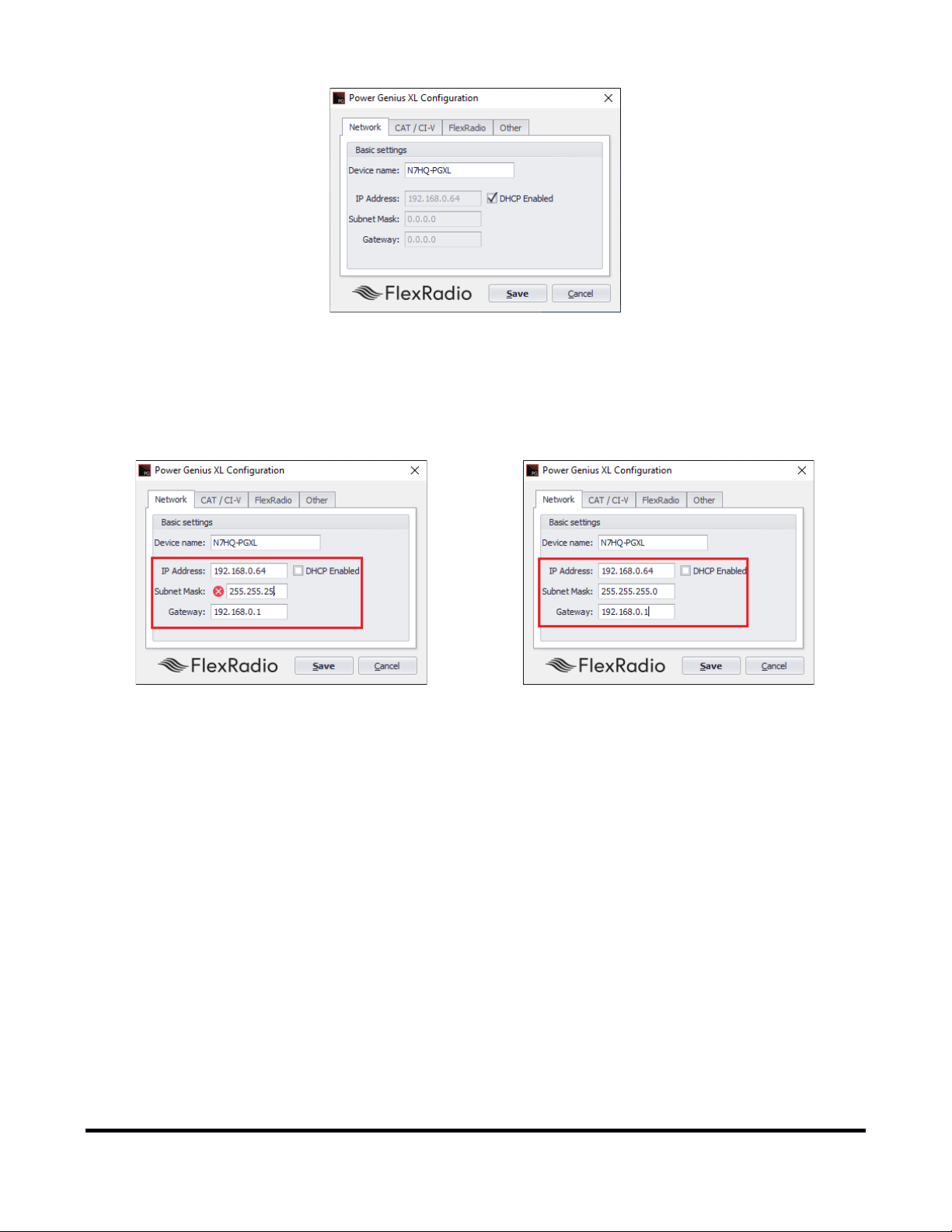
You can customize your Power Genius XL by configuring a device name and uniquely identify your amplifier. This
name will appear on the front panel of the amplifier, in the utility Available devices list, and the utility's
operational window.
• Select the Network Tab in the Configuration Dialog
• Enter an appropriate name in the device name field.
• Press Save
i – The amplifier will reboot when Save is pressed.
i – You do not need to press Save in every step. You can postpone that until you have completed all the
configuration steps.
3.3.2 Network Tab: Configuring the Network
The Power Genius XL is configured at the factory (or after a factory reset) to use DHCP IP addressing and will
automatically secure an IP Address appropriate for your network. This configuration should be sufficient for
most situations.
Page 14 of 61
Copyright 2020 FlexRadio. All Rights Reserved. August 27, 2020 (FW:3.4.16 Utility:2.2.10)
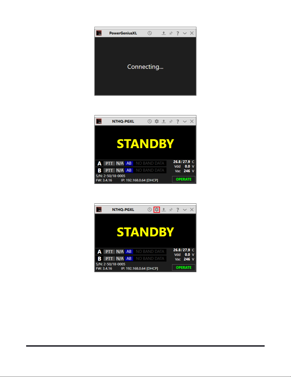
You can use the Power Genius XL Utility Network tab to assign a static IP Address, static Network Mask, and
Gateway. Static IP addresses are sometimes desirable but require specific technical knowledge of your network.
The network settings dialog performs basic validation of the network settings. Note the red X next to an
incorrectly formatted subnet mask.
If you not familiar with the rules of setting or using static IP addresses and believe you need to configure one,
please submit a HelpDesk ticket for assistance.
When you have completed configuring the network tab, it is a best practice to press Save to instruct the Power
Genius XL to store them before performing the next steps.
i – The amplifier will reboot when Save is pressed.
i – It is not necessary to exit and restart the Power Genius XL Windows Utility
i – If incorrect network information was saved, please follow the instructions in the Factory Reset the Power
Genius XL section.
3.3.3 Network Tab: Testing Network Configuration
Once you have pressed save, the configuration dialog will close, and the Power Genius XL utility will wait for the
amplifier to reboot.
Page 15 of 61
Copyright 2020 FlexRadio. All Rights Reserved. August 27, 2020 (FW:3.4.16 Utility:2.2.10)
The utility will reconnect to the amplifier when it appears on the network.
Before moving to the next step, please click the configuration (gear) icon.
Page 16 of 61
Copyright 2020 FlexRadio. All Rights Reserved. August 27, 2020 (FW:3.4.16 Utility:2.2.10)
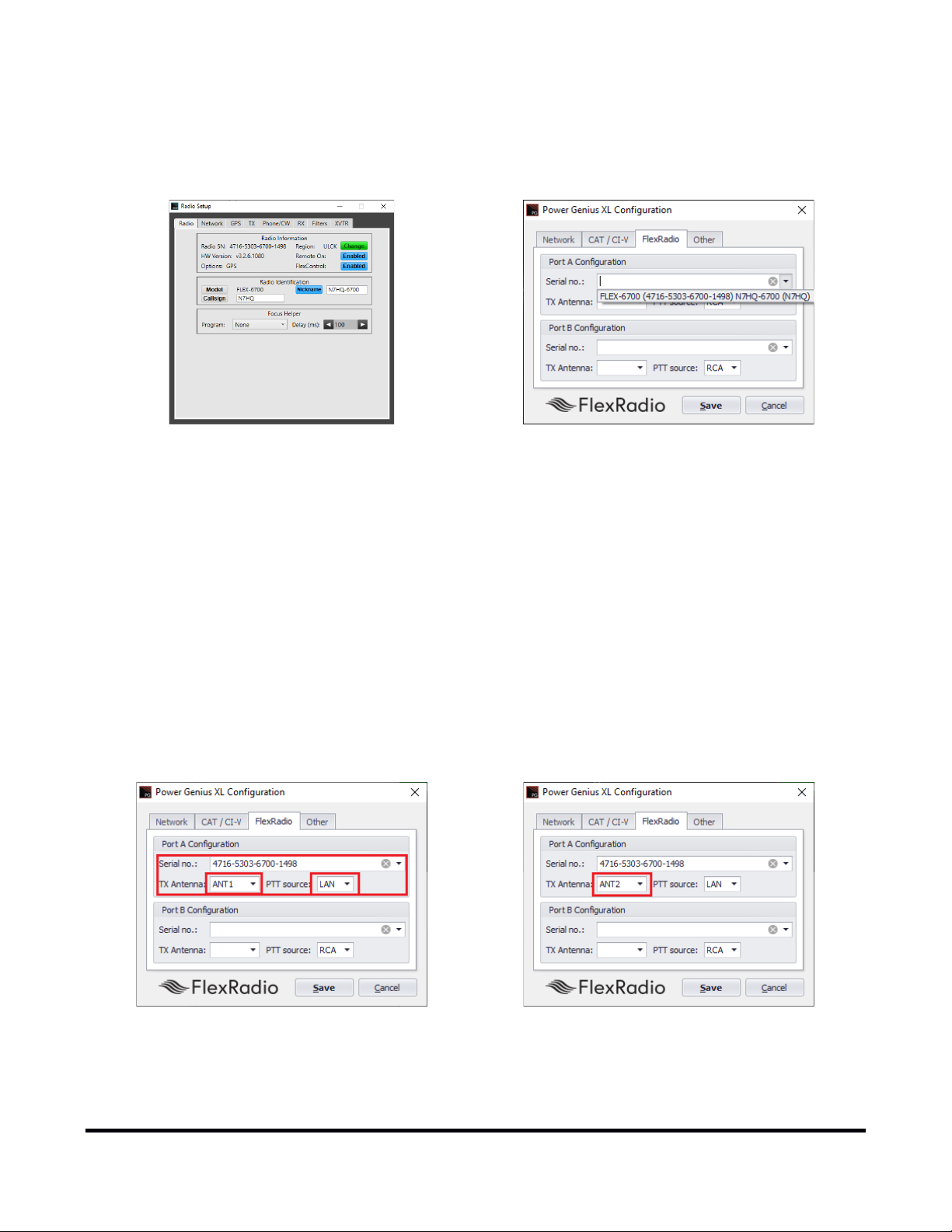
3.3.4 FlexRadio Tab: Configuring for a FLEX-6000 Series Transceive r.
Location of Radio SN
Select the discovered Radio SN
ANT1 is Connected to Port A, LAN PTT
To pair the amplifier for use with a FLEX-6000 Series transceiver, turn the radio on, then click on the FlexRadio
tab in the Power Genius XL Configuration screen
Serial Number: The utility program will detect your FLEX-6000 transceiver(s) automatically. If your radio is
connected to Port A of the amplifier, click on the Port A serial number drop-down list and select your radio. You
can find your radio's serial number on a sticker on the back panel of the radio or in the Smart SDR Radio Setup
dialog. If a FLEX-6000 transceiver is connected to Port B, make the Port B configuration settings similarly.
It is not required that you connect ANT1 output on a FLEX-6000 series connect to Port A input on the amplifier.
However, it is required that you configure which FLEX-6000 output (ANT1 or ANT2) is connected to which
amplifier port (A or B). In other words, the configuration must match the physical connection.
TX Antenna: This field configures the amplifier to follow frequency changes on that port and automatically
switch in the correct filters. For example, if ANT1 on a FLEX-6000 transceiver is connected to amplifier Port A
input, then select ANT1 as value for the Port A Configuration section. When ANT1 is selected for transmitting
on a slice, the amplifier will make the corresponding changes to its output filters, and the selected band will
appear on the amplifier's front panel and utility screen.
ANT2 is Connected to Port A, LAN PTT
Page 17 of 61
Copyright 2020 FlexRadio. All Rights Reserved. August 27, 2020 (FW:3.4.16 Utility:2.2.10)
When driven by a FLEX-6000 Series transceiver, the amplifier is optimally keyed (strongly recommended) over
the LAN connection to the radio. You can use a PTT signal wire connected to the appropriate RCA PTT Input on
the amplifier back panel. However, if you do, a ten millisecond (10ms) TX delay must be set for each Transmit
profile that uses the Power Genius XL. Select the desired keying source in the PTT Source box on the
configuration screen for each radio.
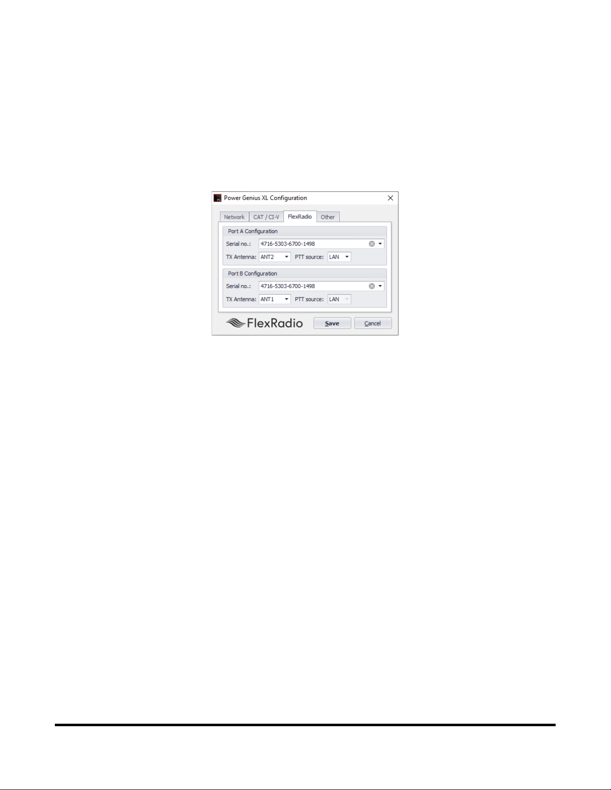
When the same FLEX-6000 transceiver is connected to both Power Genius XL ports (A and B), you can select the
same serial number for both Port A and B sections. This configuration enables advanced Single Operator Two
Radio (SO2R) operations, with a single transceiver and amplifier.
SO2R Configuration ANT2->Port A, ANT1->Port B
Click the Save button to record the configuration in the amplifier. The Power Genius XL amplifier is now
configured for use by the FLEX-6000 Series transceiver. Please proceed to section 3.5, Testing the connection
to the radio to complete the setup.
! – Do not connect another transceiver via RS-232 (CAT), CI-V, or BCD to the same amplifier Port that is
configured for a FlexRadio transceiver.
i – Do not connect a PTT line when interfacing with a FLEX-6000 transceiver. Unless some advanced need
requires the use of a separate PTT signaling wire, LAN signaling is all you need.
i – No transmit delay needs to be configured in the FlexRadio 6000 Series transceiver when using the Power
Genius XL with LAN signaling. The Power Genius XL applies the necessary delay automatically when it
interacts with the radio at the start of a transmission.
i – The LAN integration of the Power Genius XL amplifier is supported in SmartSDR Version 2.0 and later
versions. It is not supported in SmartSDR Version 1.
i – The amplifier will reboot when Save is pressed.
Page 18 of 61
Copyright 2020 FlexRadio. All Rights Reserved. August 27, 2020 (FW:3.4.16 Utility:2.2.10)
3.4 Advanced Configuration
3.4.1 Configuring the Power Genius XL
The Power Genius XL amplifier must be configured to work with the transceiver or transceivers that will drive it.
The basic configuration of the amplifier is accomplished using the Power Genius XL Utility program described
above.
The amplifier can be driven by one or two radios. When using two radios, the makes and models do not need
to be the same; each amplifier port allows a separate configuration. Follow the instructions that apply to your
circumstance, then proceed to section 3.5, Testing to complete the setup.
Start the Power Genius XL Utility program. It will find your Power Genius XL amplifier automatically. Click on
your amplifier to select it, then click on the Connect button.
The amplifier status screen will appear, as shown below. Click on the configuration settings button (outlined in
red) to open the configuration settings for the amplifier.
Page 19 of 61
Copyright 2020 FlexRadio. All Rights Reserved. August 27, 2020 (FW:3.4.16 Utility:2.2.10)

3.4.2 Required RF Output Delay (TX Delay)
The Power Genius XL firmware manages all state transitions. However, the transition from Operate to Transmit
requires that the exciter slightly delay emitting RF until the transition is complete. The Power Genius XL
requires a minimum delay of 10 milliseconds (10ms) between the time the keying signal arrives at the amplifier
and the arrival of the exciter RF signal. This time delay is necessary for the amplifier to complete all
preparations to accept and amplify a signal safely.
3.4.2.1 FlexRadio 6000-Series
When keying the amplifier with FlexRadio 6000 Series transceivers using LAN keying, no adjustment is needed
in the amplifier or in the radio to achieve the 10 ms delay. The delay is enforced automatically by the
radio/amplifier software system. There is no need to set the "TX Delay" value in the transceiver.
i – A best practice is to create a Power Genius XL TX Profile for your FLEX-6000 Series transceiver and load
that when using the Power Genius XL.
Page 20 of 61
Copyright 2020 FlexRadio. All Rights Reserved. August 27, 2020 (FW:3.4.16 Utility:2.2.10)

3.4.2.2 TX Delay for Other Exciters
Keying the amplifier with other than FlexRadio 6000 Series transceivers, you will need to use a setting in the
radio to delay the generation of RF by at least ten milliseconds (10ms) after the keying signal (PTT) is sent to the
amplifier by the exciter.
Please consult the manual for your transceiver or exciter to enable and configure the TX Delay.
3.4.2.3 Exciters Without a TX Delay Adjustment
If the exciter does not support a delay of this type, then configure the amplifier and exciter in the following
way:
• Connect the keying device (mic PTT switch, foot pedal, etc.) to the appropriate Power Genius XL PTT
Input. The appropriate input is the same amplifier port (A or B) where the exciter output is connected.
• Connect the amplifier's PTT Output (port A or B) to the exciter in place of the keying device.
When the amplifier is keyed, the Power Genius XL will then manage the output keying signal delay and asserts
PTT at the transceiver when the amplifier is ready to accept RF.
Example: Footswitch PTT wiring for a transceiver connected to Port A that does not have a TX Delay
adjustment.
Page 21 of 61
Copyright 2020 FlexRadio. All Rights Reserved. August 27, 2020 (FW:3.4.16 Utility:2.2.10)

3.4.3 Interfacing with Other Exciters
You can connect more than one type of radio to a Power Genius XL, provided each radio is exclusively
connected to one of the amplifier ports (A or B). Though each port has multiple interfaces to receive band data
and key the amplifier, the amplifier does not support multiple radios on a single amplifier port.
3.4.3.1 Elecraft
Elecraft radios require both band data and a PTT line. Band data is available using a custom wired BCD band
decoder cable.
PTT
Connect an appropriate cable (RCA male terminated on both ends) between the radio's Key output and the PTT
Input corresponding to the amplifier Port (A or B) used.
Band Data (BCD)
See the pinout diagram below for the cable configuration. The connection is the same for all Elecraft radio
models.
Page 22 of 61
Copyright 2020 FlexRadio. All Rights Reserved. August 27, 2020 (FW:3.4.16 Utility:2.2.10)

You can connect either the BCD/PTB Input A or BCD/PTB Input B connector on your PG XL to the ACC
connector on the Elecraft transceiver using a female to female DE-15 cable (DE-15 male connectors on both
ends of the cable), customized as detailed above.
Configuration
To configure the amplifier, click on the CAT/C-IV tab in the Power Genius XL Configuration screen.
Select the appropriate radio model from the Radio type drop-down menu for the amplifier port where the
radio is connected. Select the serial communication port speed and configuration parameters that apply to
your radio. Click the Save button to record the configuration in the amplifier.
i – The amplifier will reboot when Save is pressed.
Please proceed to section 3.5, Testing to complete the setup.
Page 23 of 61
Copyright 2020 FlexRadio. All Rights Reserved. August 27, 2020 (FW:3.4.16 Utility:2.2.10)

3.4.3.2 Kenwood
Kenwood radios require both band data and a PTT line. Band data is available using the CAT protocol via RS-
232.
PTT
Connect an appropriate cable between the radio's PTT output and the PTT Input corresponding to the amplifier
Port (A or B) used. Some models may require a custom cable to access radio PTT from an accessory connector.
Band Data (CAT)
RS-232 (CAT) connections use a straight-through female to female DB9 cable.
Connect either the CAT Input A or CAT Input B connector on your Power Genius XL to the CAT connector on the
Kenwood transceiver using a female to female DB9 cable.
Page 24 of 61
Copyright 2020 FlexRadio. All Rights Reserved. August 27, 2020 (FW:3.4.16 Utility:2.2.10)

Configuration
To configure the amplifier, click on the CAT/C-IV tab in the Power Genius XL Configuration screen.
Select "Kenwood" from the Radio type drop-down menu for the amplifier port where the radio is connected.
Select the serial communication port speed and configuration parameters that apply to your radio. Click the
Save button to record the configuration in the amplifier.
i – The amplifier will reboot when Save is pressed.
Please proceed to section 3.5, Testing to complete the setup.
Page 25 of 61
Copyright 2020 FlexRadio. All Rights Reserved. August 27, 2020 (FW:3.4.16 Utility:2.2.10)

3.4.3.3 Icom
Icom radios require both band data and a PTT line. Band data is available using RS-232 (CAT) or CI-V.
PTT
Connect an appropriate cable between the radio's PTT output and the PTT Input corresponding to the amplifier
Port (A or B) used. Some models may require a custom cable to access radio PTT from an accessory connector.
Band Data (CAT)
RS-232 (CAT) connections use a straight-through female to female DB9 cable.
Connect either the CAT Input A or CAT Input B connector on your Power Genius XL to the CAT connector on the
Icom transceiver using a female to female DB9 cable.
Page 26 of 61
Copyright 2020 FlexRadio. All Rights Reserved. August 27, 2020 (FW:3.4.16 Utility:2.2.10)

Band Data (CI-V)
ICOM Model
CI-V Address
IC-775
$46 (46 Hex)
IC-7000
$70 (70 Hex)
IC-7800
$6A (6A Hex)
You can connect either the CI-V Input A or CI-V Input B connector on your PG XL to the CI-V connector on the
Icom transceiver using a standard 3.5mm three-wire (TRS) or a two-wire (TR) cable.
Configuration
To configure the amplifier, click on the CAT/C-IV tab in the Power Genius XL Configuration screen.
Select the appropriate radio model from the Radio type drop-down menu for the amplifier port where the
radio is connected. Select the serial communication port speed and configuration parameters that apply to
your radio.
If your ICOM model is not listed, you will need to change the ICOM CI-V address in your radio to one of the
three values supported by the amplifier.
1. Change the CI-V address of the ICOM radio to a value supported by the Power Genius XL firmware (see
table above), and select the corresponding ICOM Model in the Power Genius XL Windows Utility.
2. Connect a PTT cable between the radio and the appropriate port (A or B) on the amplifier.
Page 27 of 61
Copyright 2020 FlexRadio. All Rights Reserved. August 27, 2020 (FW:3.4.16 Utility:2.2.10)

3. You will need to select the corresponding radio in the Power Genius XL Windows utility for this to work.
The data rate is really up to you – 9600 is just fine – however, the ICOM exciter must be set to the same
data rate as the Power Genius XL. Faster is not necessarily better as this connection is used solely for
band/frequency data.
Click the Save button to record the configuration in the amplifier.
i – The amplifier will reboot when Save is pressed.
Please proceed to section 3.5, Testing to complete the setup.
Page 28 of 61
Copyright 2020 FlexRadio. All Rights Reserved. August 27, 2020 (FW:3.4.16 Utility:2.2.10)

3.4.3.4 Yaesu
Yaesu radios require both band data and a PTT line. Band data is available using either the CAT protocol via RS232 or BCD band data from a DIN connector.
PTT
Connect an appropriate cable between the radio's PTT output and the PTT Input corresponding to the amplifier
Port (A or B) used. Some models may require a custom cable to access radio PTT from an accessory connector.
Band Data (CAT)
RS-232 (CAT) connections use a straight-through female to female DB9 cable.
You can connect either the CAT Input A or C AT Input B connector on your PG XL to the CAT connector on the
Yaesu transceiver using a female to female DB9 cable.
Page 29 of 61
Copyright 2020 FlexRadio. All Rights Reserved. August 27, 2020 (FW:3.4.16 Utility:2.2.10)

Band Data (BCD)
Alternatively, you can use a BCD connection between the eight-pin DIN (Band Data) connector on the Yaesu
transceiver to the Band Data A or Band Data B (DB15) connector on the amplifier
BCD connections, use a custom cable configured as shown in this diagram.
i – Optocouplers protect all serial and digital inputs or outputs on the Power Genius XL
Page 30 of 61
Copyright 2020 FlexRadio. All Rights Reserved. August 27, 2020 (FW:3.4.16 Utility:2.2.10)

Configuration
To configure the amplifier, click on the CAT/C-IV tab in the Power Genius XL Configuration screen.
Select the appropriate radio model from the Radio type drop-down menu for the amplifier port where the
radio is connected. Select the serial communication port speed and configuration parameters that apply to
your radio. Click the Save button to record the configuration in the amplifier.
i – The amplifier will reboot when Save is pressed.
Please proceed to section 3.5, Testing to complete the configuration.
Page 31 of 61
Copyright 2020 FlexRadio. All Rights Reserved. August 27, 2020 (FW:3.4.16 Utility:2.2.10)

3.4.3.5 Unlisted Exciters
PTT
Connect an appropriate cable between the radio's PTT output and the amplifier's PTT Input A or B jack. All
radios usually have a PTT interface. However, it is essential to check the manual of your exciter to determine
the keying voltage and current, especially with older radios. The Power Genius XL PTT lines are optoisolated,
but they will not tolerate high voltages or an AC voltage. Be prepared to provide a keying buffer relay designed
for the task., like the Ameritron ARB-704 amp to transceiver interface.
i – Some operators opt to use a keying buffer in all cases, as "insurance" to prevent any possible damage to
the exciter or amplifier due to possible transient voltage spikes or RF ingress.
Band Data
Most radios use one of these protocols to send band data to external devices:
• BCD / PTB protocol
Connect your radio or band decoder to the BCD/PTB Input A or BCD/PTB Input B connector on the
amplifier. This connection requires no additional configuration and works automatically. Band data
arriving on the BCD/PTB connection overrides other sources. See section 2.3, BCD/PTB connector
pinout for additional information.
• CAT protocol
Connect your radio's CAT output to the CAT Input A or CAT Input B connector on the amplifier.
Configure the CAT protocol details using the Power Genius XL Utility.
• CI-V protocol
Connect your radio's CI-V output to the CI-V Input A or CI-V Input B connector using a 3.5mm TS or TRS
connector. Configure the CI-V protocol details using the Power Genius XL Utility.
• Frequency Measurement
The Power Genius XL will measure the frequency of an RF signal applied to one of its inputs and
automatically switch in the appropriate filters. This mode of band switching often requires that you
double-key briefly before the transmission to allow the filter switching to complete.
Please proceed to section 3.5, Testing to complete the setup.
Page 32 of 61
Copyright 2020 FlexRadio. All Rights Reserved. August 27, 2020 (FW:3.4.16 Utility:2.2.10)

3.5 Testing
After following the instructions in Basic Configuration or Advanced Configuration, you can test the connection
to the amplifier from the radio. Turn the radio and amplifier on and select a band on the radio. The band
information should appear on the front panel of the amplifier and the Power Genius XL Windows Utility for the
port you have chosen.
Make sure all RF connections are correctly attached and tightened, and that an appropriate antenna or dummy
load is attached to the appropriate amplifier output.
Put the amplifier in OPE R ATE mode by pressing the STBY/OPER button on the amplifier's front panel or the
Operate button on the Power Genius XL Windows Utility. The Power/SWR/Id/temperature and voltage meters
should now display.
Page 33 of 61
Copyright 2020 FlexRadio. All Rights Reserved. August 27, 2020 (FW:3.4.16 Utility:2.2.10)

Change to another band and verify the amplifier follows the correct band.
Set the drive power at the transmitter to about 10 watts and transmit a carrier. The amplifier should switch
into the transmit mode.
• The front panel LED background status lights will change from green to red
• The PTT indicator on the front panel display will be red.
• The output power level should be about 15dB greater than the input power (about 300 watts for 10
watts of drive).
• The I
will increase to about 20A.
d
• SWR will be displayed along with the LDMOS drive voltage and drain current.
• The heatsink temperatures and cooling fan speeds will increase. Provided the SWR remains in the
green range of the meter, increasing the drive power should produce corresponding increases in I
and
d
output power.
Page 34 of 61
Copyright 2020 FlexRadio. All Rights Reserved. August 27, 2020 (FW:3.4.16 Utility:2.2.10)

4 Operating the Power Genius XL
Front panel "Hard" button
4.1 Changing Standby and Operate Modes
There are two ways the amplifier can be toggled between Standby and Operate modes.
1. By pressing the STBY/OPER button on the front panel of the amplifier.
2. By changing the mode using software.
Smart SDR Button
i – When properly configured, a convenient method for switching between Standby and Operate mode is
using software that is connected to the Power Genius XL over the network.
The front panel STBY/OPER button toggles the operational state between STAND BY and OPERATE mode.
Power Genius XL Utility Button
4.1.1 Standby Mode
In STAND BY mode, the amplifier power supply is disabled, and the drive signal is passed, unamplified, to the
output ports. The front panel backlights are yellow. The amplifier can remain in this mode indefinitely.
i – The Power Supply Unit (PSU) will generate some heat in Standby, and in relatively warm installation
environments, the fans that cool the PSU may engage periodically.
Page 35 of 61
Copyright 2020 FlexRadio. All Rights Reserved. August 27, 2020 (FW:3.4.16 Utility:2.2.10)

4.1.2 Operate Mode
In OPERAT E mode, the amplifier power supply is engaged, and the amplifier is prepared to receive RF Input
Drive and a PTT signal. The front panel meters are active, the LED backlights turn green, band/frequency data is
processed, and the correct filters are selected and displayed.
i – Before entering the OPERATE mode, the Power Genius XL will perform a quick self-test of all the modules.
4.2 Setting Amplifier Bias Class
The Power Genius XL has two preset amplifier bias classes. Class AB and Class AAB. You can manually select
between the two classes using the touch-screen front-panel on the amplifier or the Power Genius Windows
Utility program. Click or touch the class button on the appropriate port. The button will cycle between (Auto,
AB, and AAB).
FlexRadio 6000-Series transceivers conveniently switch the amplifiers bias class automatically
depending on the modulation mode selected by the user in Smart SDR. Manual bias switching is not
available when a FLEX-6000 series is paired and connected.
Page 36 of 61
Copyright 2020 FlexRadio. All Rights Reserved. August 27, 2020 (FW:3.4.16 Utility:2.2.10)

4.2.1 Amplifier Bias Class Modes
Modulation Mode
Amplifier Class
AM, USB, LSB, PSK
AAB
CW, FM, FSK, MFSK, Digital (see note)
AB
AB – As its name suggests, this class is a combination of class A and class B operation. This mode sets a small
bias voltage and is a good efficiency and linearity compromise between class A and B operation. Use the AB
bias class for modes where linearity is not an absolute requirement.
AAB – the amplifier operates in nearly pure class A territory, offering improved linearity at the expense of
efficiency. MEffA does not function in this class.
Auto – Used only for FlexRadio 6000-Series transceivers., the amplifier bias class is automatically selected from
the data received by the transceiver.
i – FlexRadio transceivers will switch the Power Genius XL bias class to AB when DIGU and DIGL modulation
modes are selected in Smart SDR. When you are transmitting a phase-shift keyed digital mode like PSK, we
recommend that you either disable MEffA or select USB/LSB for the modulation mode and disable any audio
processing. The operationally "better" change is disabling MEffA, as it is a less involved change, and there are
filter optimizations for DIGx modes that may of benefit.
i – The amplifier monitors the signal and determines the nature of the RF envelope. If it determines the bias
class should change, the class label will blink while the amplifier is transmitting and will change to the new
bias class when the transmission ends.
Copyright 2020 FlexRadio. All Rights Reserved. August 27, 2020 (FW:3.4.16 Utility:2.2.10)
Page 37 of 61

4.3 Transmitting
When the amplifier is transmitting, the front panel display looks similar to this:
The elements of this display are described in the following sections.
4.3.1 Power Meter (PWR)
The power meter indicates the transmitted peak and average power. It ranges from 0 to over 2000W. When
operating above 1500 watts, the meter is shown in red. When the MEffA indicator is displayed, the MEffA
algorithm is optimizing the amplifier's operating point.
i – Power measurements update approximately every 100ms and should be used for reference only. For an
accurate power reading, transmit a fixed amplitude and frequency signal for at least 1 second.
i – The MEffA indicator on the Power Genius XL Windows Utility is "clickable," and allows the operator to
switch MEffA mode ON or OFF.
Page 38 of 61
Copyright 2020 FlexRadio. All Rights Reserved. August 27, 2020 (FW:3.4.16 Utility:2.2.10)

4.3.2 SWR meter
The SWR meter shows the Standing Wave Ratio (SWR) on the transmitting antenna. The maximum working
SWR allowed by the amplifier is 3:1. Output power will be reduced when the SWR exceeds 2:1. Above 3:1, the
amplifier will raise the HIGH SWR alarm and stop transmitting.
4.3.3 Id Meter
meter shows the LDMOS drain current in Amperes. It ranges from 0A to 70A.
The I
d
4.3.4 PTT and Band Data
These displays show the PTT information, band data, amplifier operating class, and the source of the band data
for Ports A and B. The PTT label is red when PTT input is detected, and the amplifier is transmitting. The green
labels show the selected band. When no band data is present, these labels will display N/A (not available).
The blue label indicates LDMOS bias class. Class AB operation is optimal for single tone modes, while class AAB
is best for SSB and AM. While transmitting, the amplifier monitors the signal and determines the nature of the
envelope. If it decides the bias class should change, the class label will blink while the amplifier is transmitting,
and the class will change when the transmission ends.
Labels to the right indicate the band data source, which will be one of:
• A FLEX-6000 Series transceivers, in which case it will display your radio's name
• BCD band data
• PTB band data
• CAT band data
Page 39 of 61
Copyright 2020 FlexRadio. All Rights Reserved. August 27, 2020 (FW:3.4.16 Utility:2.2.10)

4.3.5 Temperature and Voltage
The bottom right part of the display shows:
t the temperatures (Celsius) of the PA heatsink and Harmonic Load heatsink
V
the LDMOS drain voltage
dd
V
the AC supply voltage
ac
The optimal operation is below 60 °C. Above 60 °C, the amplifier will decrease output power to protect it from
damage. If the temperature exceeds 85° C, the amplifier will fault and stop transmitting until the temperature
drops. Cooling fan speeds are controlled automatically by the firmware using the selected profile.
Typical V
values range from 30V to 53VDC. Vdd is determined automatically by the output transistor
dd
temperature and amplifier efficiency.
4.3.6 Additional Information
This section shows the amplifier serial number, device name, firmware version, the IP address, and IP
Addressing mode.
Page 40 of 61
Copyright 2020 FlexRadio. All Rights Reserved. August 27, 2020 (FW:3.4.16 Utility:2.2.10)

4.4 Status LED (Backlight)
Backlight Color
Operational Mode
Yellow
Standby
Green
Operate
Red
Transmit
Magenta
Firmware Upgrade in Progress
The front-panel LED backlight shows the current operational state:
4.4.1 Standby Mode – Yellow backlight
The yellow backlight indicates the amplifier is in STAND BY mode. To change to OPE R ATE mode, press the
STBY/OPER button on the front panel.
4.4.2 Operate Mode – Green backlight
Copyright 2020 FlexRadio. All Rights Reserved. August 27, 2020 (FW:3.4.16 Utility:2.2.10)
Page 41 of 61

The green backlight indicates the amplifier is in the OPER AT E mode. To change to STAN D BY mode, press the
STBY/OPER button on the front panel.
4.4.3 Transmitting – Red backlight
The red backlight indicates the amplifier is transmitting.
4.4.4 Firmware Upgrade in Progress– Magenta backlight
The magenta backlight indicates the amplifier is in firmware upgrade mode. The display will show the
bootloader version and IP address of the device. Once the upgrade is complete, the amplifier will restart.
i – When the amplifier is first turned on, these status LEDs gradually brighten, meant to simulate a
tube filament warming up.
Page 42 of 61
Copyright 2020 FlexRadio. All Rights Reserved. August 27, 2020 (FW:3.4.16 Utility:2.2.10)

4.5 120 VAC Operations
The Power Genius XL uses a commercial-grade AC / DC power converter to run the amplifier. The Power Supply
Unit (PSU) is rated at its full output power when it is supplied with more than 200 volts AC (50 or 60 Hz). The
amplifier can be operated on less than 200 VAC, but at a reduced power level. In particular, it can be operated
on 120 VAC, a standard wall-socket voltage in the US.
When operated on 120V AC, the amplifier automatically de-rates its performance in the following ways:
1. Reduces the maximum output power to 700 watts
2. Reduces the APC fold-back threshold to 650 watts.
3. Reduces gain to about 12 dB.
4. Rescales the front panel and Utility program Power meters to 1000 watts maximum.
i – When the amplifier is operated between 650 and 700 watts, the APC system will reduce power to about
650 watts.
i – When operated is attempted above 700 watts, the amplifier fault, turn off the power supply to protect it
from overload and display the "PLEASE UNKEY" message. To clear the overload, you must unkey (stop
transmitting).
Page 43 of 61
Copyright 2020 FlexRadio. All Rights Reserved. August 27, 2020 (FW:3.4.16 Utility:2.2.10)

5 Maximum Efficiency Algorithm (MEffA™)
The Maximum Efficiency Algorithm (MEffA) controls the operational parameters of the amplifier to maximize
the linearity of the amplified signal, minimize Intermodulation Distortion products, and maximize efficiency.
The amplifier adjusts drive voltage and bias settings based on the type of the input signal. When a pure carrier
signal such as a CW signal is input, the amplifier operates in class-AB and can achieve an efficiency approaching
75%. When an SSB signal is input, the amplifier operates in class AAB, between class A, which is the most
linear, but least efficient, and class AB, which is more efficient, but less linear.
MEffA does not work with signals with varying amplitudes, such as SSB, AM, or phase-shift keying digital modes
like PSK-31. These modulation modes require more linear operation (class AAB). Though the MEffA indicator
may be on, it is only operational in class AB operation and does not affect class AAB operation.
You can operate in class AB without MEffA, which still provides an improvement in amplifier efficiency for
constant level signals, relative to maximum linearity amplification.
To adjust MEffA for operation at the desired power level:
• Key the amplifier with a "Tune" or drive signal, to establish the desired output.
• Unkey the amplifier and re-key. You may note that the amplifier has reduced the LDMOS Drain Voltage,
and correspondingly reduced the output level.
• Increase the drive again to re-establish the desired output level.
• Repeat this process until the desired output power is consistently achieved.
You are now ready to operate.
If you don't want to go through this process, you can leave the MEffA box unchecked in the Power Genius XL
Utility program tab "Other" and use a fixed drive level that will correspond to fixed power output on a given
band.
Page 44 of 61
Copyright 2020 FlexRadio. All Rights Reserved. August 27, 2020 (FW:3.4.16 Utility:2.2.10)

6 Automatic Power Control (APC)
Automatic Power Control (APC) is a system that reduces output power when an operating limit is exceeded,
preventing damage to the amplifier. Reacting in about one microsecond (1µsec), it monitors output power,
VSWR, and driver temperature. When peak output power exceeds a preset limit, APC will reduce the output
power, and the APC alarm will be shown on the amplifier's front panel. APC will limit output power to 2000
watts on all bands except 160 and 20, where it triggers at 1650 and 1750 watts, respectively.
i – The control operator has the sole responsibility for limiting the output power of the amplifier to a value at
or below his or her licensed limit. APC is not responsible for and does not enforce this limit.
i – When VSWR of more than 2:1 is detected, APC reduces output power to a safe level, allowing for
continued operation. If VSWR exceeds 3.1:1, APC switches the amplifier to STANDBY mode and displays the
HIGH SWR alarm.
i – When APC detects that the PA heat sink temperature is nearing its upper limit, it reduces the output
power if the MEffA system cannot contain the temperature. When the amplifier cools to 60°C, APC will
restore full power.
Page 45 of 61
Copyright 2020 FlexRadio. All Rights Reserved. August 27, 2020 (FW:3.4.16 Utility:2.2.10)

7 Harmonic Load
Solid-state Amateur Band RF power amplifiers typically use low pass filters to suppress harmonic distortions
during amplification to meet jurisdictional regulations limiting emissions that can cause interference in other
frequency bands. With traditional amplifier designs, this harmonic energy is reflected from the low pass filters
back into the output stage and can cause damaging voltage spikes and additional non-linearities.
In addition to a set of low pass filters, the Power Genius XL employs separate high pass filters that route
generated harmonics to an internal 400-watt dummy load, called the Harmonic Load. Commonly found only in
broadcast-grade transmitters, unwanted harmonic energy is not reflected to the output stage and is safely
dissipated. This design improves linearity and allows the amplifier to achieve the same fundamental power
output with less LDMOS device peak drain voltage.
The Harmonic Load in the Power Genius XL is mounted on a dedicated heat sink, with independent thermal
management, using a discrete temperature sensor and fan controller.
Page 46 of 61
Copyright 2020 FlexRadio. All Rights Reserved. August 27, 2020 (FW:3.4.16 Utility:2.2.10)

8 Thermal Management (Cooling)
There are three independently managed fan assemblies in the Power Genius XL; controlled fans manage each
based on discrete temperature sensors in the area that they cool.
The Power Genius XL Utility program allows an option to select one of three active fan profiles; "Normal,"
"Contest," and "Broadcast," as a default, active when the amplifier is turned on or after a reboot.
"Normal" is the least aggressive (most quiet) profile. The fans run more slowly when the amplifier is cool and
ramp using a non-linear hysteresis curve as the cooling domains in the amplifier increase in temperature.
The "Contest" profile uses a more aggressive hysteresis curve and anticipates continuous heavy use, such as
might be encountered in a contest situation.
The "Broadcast" profile, sets all fans to maximum speed while the amplifier is in OPER AT E mode.
Independent of the selected fan profile, the unit will always manage the fans to the speed necessary to protect
the amplifier. Some combinations of frequency and power levels will cause the fans to run at higher speeds
because these configurations are known to generate more heat.
8.1 Power Supply Unit (PSU) Fans
The Power Supply Unit (PSU) is a self-contained unit that manages all thermal aspects, including its fan speed.
There is no end-user control available to adust the thermal management of the PSU.
i – When the amplifier is in STANDBY or OPERATE mode and is not transmitting, the current draw is low, but
the temperature will gradually rise in the PSU. The PSU may occasionally cycle its fans to keep the
temperature within a safe range.
8.2 Power Amplifier (PA) Fans
Three fans cool the Power Amplifier compartment and heat sink. The PA fans will go to maximum speed when
the PA temperature is sensed above 75°C, regardless of fan profile. At or above 85°C, the amplifier will issue a
fault and shut down to protect itself.
i – MEffA mode reduces current requirements and will reduce the need for high cooling fan speeds.
8.3 Harmonic Load and Filter Compartment Fan
The Harmonic Load and Filter Compartment fan will go to the maximum speed at Harmonic Load heat sink
temperature of 65°C or higher, regardless of fan profile selection. The Harmonic Load and filter compartment
in the Power Genius XL can be safely operated to 110°C, at which point the amp will issue a fault and shut
down.
Page 47 of 61
Copyright 2020 FlexRadio. All Rights Reserved. August 27, 2020 (FW:3.4.16 Utility:2.2.10)

This fan also obeys an algorithm that follows the PA heatsink temperature and accumulated key-down time. As
the PA temperature increases, the minimum Harmonic Load fan speed increases. Similarly, as the amount of
key-down time in the last 30 seconds (on 6M, 10M, and 20M) or the last 120 seconds (all other bands)
increases, the fan speed increases. All these inputs work together to make sure that the Harmonic Load and
Filter unit is always adequately cooled.
The Harmonic Load dissipates more energy when the amplifier is running in class AB, and even more when
MEffA is enabled. In those circumstances, it is normal for the harmonic load to record a higher temperature
than the PA. The more linear class AAB operation is less efficient, so generally, the PA heatsink will run warmer
than the Harmonic Load since less harmonic energy is created.
In all cases, fan speeds are continuously adjusted to keep the amplifier within safe temperature limits.
9 The Power Genius XL Windows Utility
In addition to the amplifier configuration tasks described in the previous sections, the Power Genius XL Utility
provides several other features.
9.1 Windows Utility Front Panel Display
The Power Genius XL Utility provides a remote copy of the amplifier's front panel display that is updated as the
amplifier runs.
The title bar of the screen includes a button that opens the configuration screens, a button that opens the
firmware update screen, and a button that pins the screen so that it is always on top of other screens.
Page 48 of 61
Copyright 2020 FlexRadio. All Rights Reserved. August 27, 2020 (FW:3.4.16 Utility:2.2.10)

9.2 Standby Operate Mode
The utility application also provides a STANDBY/OPE R ATE button in the lower right corner of the screen.
Clicking this button changes the amplifier from STAN D BY mode to OPERAT E mode and back.
9.3 Active Fan Profile
Just to the left of the STBY/OPER button is a small button that allows you to change the active fan profile. Click
this button to change the fan profile to Standard (S), Contest (C), or Broadcast (B). The change to the fan profile
takes place immediately but is not recorded in the amplifier's memory. The next time the amplifier is started, it
will revert to the fan mode that is set using the Other tab on the Configuration dialog. To make the fan mode
change permanent, use the Save button on the Configuration screen.
9.4 MEffA Indicator
Immediately above the PWR meter, you will see the MEffA indicator. Clicking on the indicator will toggle the
MEffA system on and off. As with the fan mode button, the change is not recorded in the amplifier's
configuration memory. To make the MEffA mode change permanent, use the Save button on the Configuration
screen.
9.5 Amplifier Configuration Dialog
Clicking the Configuration button (gear icon) at the top right of the Power Genius XL Utility screen opens the
amplifier configuration dialog.
Page 49 of 61
Copyright 2020 FlexRadio. All Rights Reserved. August 27, 2020 (FW:3.4.16 Utility:2.2.10)

9.5.1 Network Tab
The Network tab is used to configure the device name and the amplifier network interface.
9.5.1.1 Device Name
The Power Genius XL Utility supports creating custom "Device Name" to an amplifier. This name is simply a
short text string that is associated with a specific amplifier. It can be set, changed, and cleared on the Network
tab of the Configuration screen, as shown below:
In this case, the user has set the nickname to N7HQ-PGXL. The nickname will appear in the Utility program's
chooser, as shown below and in the title bar of the Utility program's main screen:
i – The default nickname is "PowerGeniusXL."
Page 50 of 61
Copyright 2020 FlexRadio. All Rights Reserved. August 27, 2020 (FW:3.4.16 Utility:2.2.10)

9.5.1.2 Basic Settings
Here you can select between a DHCP supplied IP Address or configure the amplifier to use a static IP address.
See section 9.5.1, Network Tab for details.
9.5.2 CAT/CI-V Tab
Use the CAT / CI-V tab when a FlexRadio 6000 Series transceiver does not control the amplifier. Choose the
make and model of the transceiver that is connected to each of the amplifier ports and the details of the
communication protocol between the radio and the amplifier. A selection of radio makes, and models are
provided. Do not use this tab to configure FLEX-6000 Series transceivers. Click the Save button after the
choices have been made.
Page 51 of 61
Copyright 2020 FlexRadio. All Rights Reserved. August 27, 2020 (FW:3.4.16 Utility:2.2.10)

9.5.3 FlexRadio Tab
Use the FlexRadio tab to configure the amplifier to pair with FLEX-6000 Series transceivers.
Before beginning this configuration, make sure your FLEX-6000 Series transceivers are turned on and connected
to the same logical network on LAN that hosts the Power Genius XL. The Power Genius XL utility will discover
the FLEX-6000 Series transceivers over the network.
You must select the serial number of the radio connected to each port. Leave the serial number field blank if
you do not want that port paired with a FLEX-6000 Series transceiver.
Select the antenna port from the FLEX radio (ANT1 or ANT2) that is connected to the amplifier port (A or B)
Be sure to select LAN for the PTT source, using RCA as the PTT source for FLEX-6000 Series transceivers not
recommended.
Click the Save button to store the configuration after the choices have been made.
i – The amplifier will reboot when Save is pressed.
Page 52 of 61
Copyright 2020 FlexRadio. All Rights Reserved. August 27, 2020 (FW:3.4.16 Utility:2.2.10)

9.5.4 Other Tab
Use the Other tab to adjust the front panel backlight intensity, the cooling fan operational mode, and the
default MEffA (On or Off) state.
Operation Status LED Intensity
This control sets the intensity for the LEDs on the front panel. The LED brightness does not change when
moving the control. You must click the save button to observe the change in brightness.
Fan Profiles
• Standard– the fans run at low speed, increasing speed with temperature but optimized for lowest fan
noise. Standard mode is recommended for casual SSB, CW, and digital operation.
• Contest – the fans run at a higher initial speed, increasing speed with temperature. Fan noise is louder
than in Standard mode. Contest mode is recommended for contesting or extended SSB, CW or digital
operation.
• Broadcast – the fans run continuously at high speed, regardless of temperature. Broadcast mode is
recommended for extended high power RTTY and digital mode operation, high duty cycle SO2R
contesting, or situations in which the amplifier is located away from the operating position.
MEffA
The MEffA checkbox enables or disables the state the MEffA feature will be in when the amplifier is turned on
or is rebooted. See section 5, MEffA, for more information.
i – You must press Save and reboot the amplifier to change the Status LED intensity.
i – Please don't confuse Status LED intensity with the brightness level control for the front panel display. The
front panel display operates at a fixed brightness and will drop into a screen-saver mode about 30 seconds
after transmitting, or a band change operation concludes.
Page 53 of 61
Copyright 2020 FlexRadio. All Rights Reserved. August 27, 2020 (FW:3.4.16 Utility:2.2.10)

9.6 Usage Chart
The Power Genius XL Utility collects operational data from the amplifier and can chart that data on a graph over
time. The Usage Chart button in the Utility's menu bar displays the chart.
In the following example chart, we see two transmissions over a short period.
i – Up to 2 hours (120 minutes) of data is collected and stored on the PC hard drive.
Page 54 of 61
Copyright 2020 FlexRadio. All Rights Reserved. August 27, 2020 (FW:3.4.16 Utility:2.2.10)

10 Firmware Upgrade Procedure
The Power Genius XL Utility can be used to upgrade the firmware in your Power Genius XL amplifier over the
network. Start the utility program and connect to the amplifier.
1. If the amplifier is in OP E R ATE mode, click the STBY/ OPE R button to change to STA NDBY mode.
2. Click the firmware upgrade button, and the Power Genius XL Firmware Upgrade dialog will appear:
3. Click the Browse button on the Firmware Upgrade dialog, navigate to the firmware image and select it,
then click the UPGRADE button to start the firmware upgrade process.
• The firmware will enter the boot lo ad er.
• The color of the LED status lights on the Power Genius XL will change to magenta.
• The firmware image will be transferred over the network to the amplifier.
• The amplifier will reboot.
• When the firmware transfer is complete, a status dialog will be shown.
4. Click the OK button to close the notification dialog
5. Close the Firmware Upgrade dialog by clicking the X in the top right corner.
Page 55 of 61
Copyright 2020 FlexRadio. All Rights Reserved. August 27, 2020 (FW:3.4.16 Utility:2.2.10)

During the reboot, the Power Genius XL Utility screen may show that it is connecting. After the reboot is
complete, the amplifier will reconnect, enter Standby mode, and you may resume regular operation.
Page 56 of 61
Copyright 2020 FlexRadio. All Rights Reserved. August 27, 2020 (FW:3.4.16 Utility:2.2.10)

11 Factory Reset the Power Genius XL
Alarm Message
Description
HIGH SWR
High SWR has been detected on the output port.
WRONG BAND
Band data not detected. Check your band data
settings/connections/sources.
CB NOT ALLOWED
The amplifier is set to a band it cannot use.
PLEASE UNKEY
The amplifier needs to make a change that can only be done when
it is unkeyed.
The configuration of the Power Genius XL can be reset to the "factory defaults" using the following procedure:
• Turn the amp off using the power switch on the back panel.
• Press and hold STBY/OPER front panel button
• Turn ON the amplifier.
• When you see a blue circle on the front-panel display, release the STBY/OPER button.
• Tap the blue circle with your finger. Another blue circle will be displayed at a different position on the
display - tap it. Continue tapping the blue circles until the self-test results are shown on the front panel
display.
• Start the Power Genius XL Utility. You should now be able to connect to the amp.
• Set all configuration options as desired and then click SAVE. If you do not click SAVE, the new settings
will not be retained, and you will have to rerun the reset procedure.
12 Alarms
If the amplifier detects an operational error, a message is displayed on the main display, as shown below:
The alarms and their meanings are shown in the following list:
When an alarm is raised, the amplifier disengages to protect itself from damage. The alarm is cleared when the
PTT is released.
Page 57 of 61
Copyright 2020 FlexRadio. All Rights Reserved. August 27, 2020 (FW:3.4.16 Utility:2.2.10)

13 Specifications
PA Specifications
• RF Power Output 1500W (ICAS)
• Exciter Drive Level ~50W
• Drive Transistors 2 - NXP MRF1K50H
• Exciter Inputs 2 – SO-239
• Antenna Outputs 2 – SO-239
• Antenna Impedance 50 ohms unbalanced
• Cooling Thermostatically Controlled Fans
Mechanical Specifications
• Dimensions 6” H x 14” W x 20” D, 15.5cm H x 35.5cm W x 51 cm D
• Weight 38 pounds, 17 Kg
• Shipping weight 47 pounds, 21.5 Kg
• Operating Temperature -25°C to +60°C
Electrical Specifications
• Supply Voltage and Current 90 – 250VAC, 50/60Hz, up to 15A
• Power Supply Internal Modular/Switching
14 FCC Statement
This device complies with part 15 of the FCC Rules. Operation is subject to the following two conditions:
• This device may not cause harmful interference, and
• this device must accept any interference received, including interference that may cause undesired
operation
FCC ID:
2AK7NSKYPower Genius XL001
Page 58 of 61
Copyright 2020 FlexRadio. All Rights Reserved. August 27, 2020 (FW:3.4.16 Utility:2.2.10)

15 Appendix
15.1 Installing the Power Genius XL Utility
The Power Genius XL Utility program is an integral part of the amplifier system. The utility is used to configure
the amplifier, update the amplifier's firmware, and operate the amplifier remotely. Section 9, Features of the
Power Genius XL Utility of this document, describes the features and usage of the program in detail.
Download the installer for the program from the FlexRadio website and install the program on a Windows PC
located on the same local area network as the amplifier.
The installer can be found in the software section of the FlexRadio website:
https://www.flexradio.com/category/power-genius-xl/
During installation, if you encounter a message similar to the one below, please click on the More info link.
You can then click the Run anyway button to run the installer.
You will be presented with a dialog where you select the desired language and press, OK.
Page 59 of 61
Copyright 2020 FlexRadio. All Rights Reserved. August 27, 2020 (FW:3.4.16 Utility:2.2.10)

Decide if you want a desktop shortcut created, then press Next >. Finally, when ready, press Install.
When the installer completes, you see a choice to run the Power Genius XL utility. Ensure that box is checked,
and click Finish.
When the utility runs the first time, Windows Firewall may query you for permission to open a port on your PC
needed for the Power Genius Utility to communicate with the amplifier. You can choose to allow the
application to function on Private Networks, Public Networks, or both network types. Click Allow access to
complete the installation.
i – Windows Updates have, in the past, changed the network type from Private to Public without warning. If
your PC is not a laptop you travel with, a best practice is to select both network types, to prevent problems if
a Windows update alters your network type.
Page 60 of 61
Copyright 2020 FlexRadio. All Rights Reserved. August 27, 2020 (FW:3.4.16 Utility:2.2.10)

When the utility completely loads, it will detect any Power Genius XL amplifiers that are ON and active on your
LAN then display them in a list. Please proceed with Connecting the Power Genius XL Windows Utility.
Page 61 of 61
Copyright 2020 FlexRadio. All Rights Reserved. August 27, 2020 (FW:3.4.16 Utility:2.2.10)
 Loading...