


®
www.flex-radio.com
sales@flex-radio.com
(512) 535 - 4713
Version 2.0

S O F T WA RE D E FI N E D R AD I O
The FLEX-3000 Owner's Manual
2003-2010 FlexRadio Systems®
All Rights Reserved
Reproduction of this document in any form is expressly forbidden unless explicitly
authorized by FlexRadio Systems.
Information contained in this document may contain technical inaccuracies or typographical
errors. Information may be changed or updated without notice. FlexRadio Systems may
make improvements and/or changes in the materials at any time without notice.
All materials are provided "as is". FlexRadio Systems makes no representations or
warranties, expressed or implied to the accuracy of the copyrighted materials. FlexRadio
Systems will not be liable for any direct, indirect, special or consequential damages arising
out of any use of the document.
The and the textual equivalent “FlexRadio Systems®” logo is a
registered trademark of Bronze Bear Communications doing business as FlexRadio
Systems.
“FlexRadio Systems PowerSDR™”, PowerSDR™ ,“Tune in Excitement!™”,”Excitement to
Go™”, “Excitement Anywhere™”, SDR-1000™, FLEX-5000™, FLEX-3000™, FLEX-1500™,
FlexWire™, ClickTune™, MultiRX™, PanaFall™ and PanaScope™, are all trademarks owned
exclusively by FlexRadio Systems. While portions of PowerSDR software are distributed
under the GPL Open Source License, the PowerSDR trademark is owned exclusively by
FlexRadio Systems.
13091 Pond Springs Rd #250• Austin, TX 78729
Phone: (512) 535-4713• Fax: (512) 233-5143
FlexRadio Systems
Email: sales@flex-radio.com
Editor: Joe de Groot – AB1DO
Printer/Distributor: Peter Markavage - WA2CWA
F3K-M2.0/4 iii 2003-2010 FlexRadio Systems

Table of Contents
PREFACE ....................................................................................XI
ACKNOWLEDGMENTS...............................................................XV
USING THIS MANUAL IN ITS PDF FORM.................................XVII
REFERENCE TO SOFTWARE CONTROLS.................................XIX
1 HARDWARE INSTALLATION.......................................................1
UNPACKING AND DECIDING ON A LOCATION..............................................................1
Contents of the Carton...................................................................................................1
Location Considerations.................................................................................................2
PHYSICAL CONNECTIONS.............................................................................................3
Front Panel...................................................................................................................3
(1) Power Switch....................................................................................................................3
(2) Straight Key or Paddles (KEY)..............................................................................................3
(3) Microphone Connector........................................................................................................4
(4) Headphone Jack................................................................................................................5
Back Panel...................................................................................................................5
(1) 13.8 VDC Power Socket......................................................................................................5
(2) RF Ground Terminal...........................................................................................................5
(3) Antenna Port.....................................................................................................................5
(4) IEEE 1394 FireWire Jack.....................................................................................................6
(5) PTT Jack...........................................................................................................................6
(6) External Keying Line...........................................................................................................6
(7) Powered Speaker Jack........................................................................................................6
(8) FlexWire™ Peripheral Interface Bus......................................................................................7
SPECIFICATIONS AND ARCHITECTURE.........................................................................8
FLEX-3000 Transceiver Specifications...............................................................................8
FLEX-3000 Architecture................................................................................................10
Declarations of Conformity............................................................................................11
FCC.....................................................................................................................................11
EU Compliance......................................................................................................................11
F3K-M2.0/4 v 2003-2010 FlexRadio Systems

T A B L E O F C O N T E N T S
2 SOFTWARE INSTALLATION......................................................13
SWITCH OFF THE FLEX-3000 AND INSTALL THE FIREWIRE DRIVER...........................13
Collecting Your Information...........................................................................................14
Installing the FireWire Driver........................................................................................20
Installing PowerSDR.....................................................................................................27
POWER UP THE FLEX-3000 TO COMPLETE THE INSTALLATION..................................28
Windows Vista and Windows 7......................................................................................29
Windows XP................................................................................................................29
3 POWERSDR SETUP & CONFIGURATION..................................33
SETUP WIZARD..........................................................................................................33
CONFIGURATION........................................................................................................37
Transfer of Calibration Data..........................................................................................37
Audio Mixer................................................................................................................38
READY TO START OPERATING....................................................................................38
4 OPERATION..............................................................................39
POWER-UP PROCEDURE.............................................................................................40
POWER-DOWN PROCEDURE.......................................................................................40
TUNING METHODS......................................................................................................41
Spectrum Drag and Click........................................................................................................41
Mouse Wheel........................................................................................................................41
Mouse Wheel Hover...............................................................................................................41
Spectrum Click Tuning...........................................................................................................41
Keyboard Keys......................................................................................................................42
USB Tuning Knob..................................................................................................................42
VOICE OPERATION.....................................................................................................43
CW OPERATION..........................................................................................................46
Initial Settings............................................................................................................47
Internal Keyer.............................................................................................................48
External Keyer............................................................................................................50
CWX Form..................................................................................................................50
Third Party CW Program...............................................................................................51
DIGITAL OPERATION.................................................................................................53
5 FRONT CONSOLE.....................................................................59
(1) VFO A...................................................................................................................60
(2) TUNING CONTROLS..............................................................................................60
(3) VFO B...................................................................................................................61
(4 ) MULTIMETER.......................................................................................................61
RX Meters...................................................................................................................62
TX Meters...................................................................................................................62
(5) BAND SELECTION & BAND STACKING MEMORIES.................................................63
(6) MODE SELECTION.................................................................................................64
(7) FILTER CONTROLS................................................................................................65
Labeled Filter Buttons..................................................................................................65
Variable Filter Buttons..................................................................................................66
(8) MODE SPECIFIC CONTROLS..................................................................................67
Phone Controls ...........................................................................................................67
F3K-M2.0/4 vi 2003-2010 FlexRadio Systems

T A B L E O F C O N T E N T S
CW Controls................................................................................................................68
Digital Controls...........................................................................................................70
(9) DISPLAY CONTROLS.............................................................................................70
Screen Controls...........................................................................................................71
Display Selection Controls............................................................................................71
Display Type Descriptions.............................................................................................71
Spectrum.............................................................................................................................72
Panadapter (Panoramic Adapter).............................................................................................72
Waterfall..............................................................................................................................73
Histogram............................................................................................................................74
Scope..................................................................................................................................74
Phase..................................................................................................................................75
Panafall...............................................................................................................................75
Panascope............................................................................................................................75
Off......................................................................................................................................75
Cursor and Peak Position........................................................................................................75
(10) MULTIRX CONTROLS..........................................................................................76
(11) DSP CONTROLS..................................................................................................77
(12) VFO CONTROLS...................................................................................................78
(13) CPU %................................................................................................................78
(14) START/STOP BUTTON.........................................................................................79
(15) MON (MONITOR)................................................................................................79
(16) MOX (MANUALLY OPERATED TRANSMIT)...........................................................79
(17) MUT (MUTE).......................................................................................................79
(18) RECORD () AND PLAY ()................................................................................80
(19) TUN (TUNE)........................................................................................................80
(20) ATU AND BYP.....................................................................................................80
(21) AF (AUDIO FREQUENCY GAIN)...........................................................................81
(22) AGC-T (AGC MAXIMUM GAIN)............................................................................81
(23) DRIVE (TRANSMITTER POWER OUTPUT/TUNE POWER).....................................81
(24) AGC (AUTOMATIC GAIN CONTROL)....................................................................82
(25) RX GAIN.............................................................................................................82
(26) SQL (SQUELCH)..................................................................................................82
(27) DATE/TIME DISPLAY..........................................................................................82
(28) SETUP FORM.......................................................................................................83
(29) – (34) OPERATING FORMS.................................................................................83
6 OPERATING FORMS.................................................................85
(29) MEMORY FORM...................................................................................................86
Save… .......................................................................................................................86
Recall…......................................................................................................................87
(30) WAVE FORM.......................................................................................................88
Playback...............................................................................................................................................89
Playlist..................................................................................................................................................89
Record..................................................................................................................................................89
TX Gain (dB).........................................................................................................................................89
Quick Rec and Quick Play........................................................................................................................89
Record Options............................................................................................................90
Receive.................................................................................................................................................90
Transmit...............................................................................................................................................90
Sample Rate..........................................................................................................................................90
(31) EQUALIZER FORM...............................................................................................91
3-Band Equalizer.........................................................................................................91
F3K-M2.0/4 vii 2003-2010 FlexRadio Systems

T A B L E O F C O N T E N T S
10-Band Equalizer.......................................................................................................92
(32) XVTRS FORM......................................................................................................93
(33) CWX FORM.........................................................................................................95
Standard CWX Controls................................................................................................95
CWX Memories......................................................................................................................96
Special Characters.................................................................................................................96
Keyboard and Extended Controls...................................................................................97
Extended CWX Controls..........................................................................................................97
Morse Definition Editor...........................................................................................................98
(34) MIXER..............................................................................................................100
Input..................................................................................................................................................100
Output................................................................................................................................................100
VOLTAGE AND TEMPERATURE INFORMATION..........................................................101
7 SETUP FORM..........................................................................103
GENERAL TAB...........................................................................................................105
Hardware Config Sub-Tab............................................................................................105
Radio Model.........................................................................................................................................105
FLEX-3000 Config.................................................................................................................................105
Receive Only........................................................................................................................................106
DDS...................................................................................................................................................106
Options Sub-Tab........................................................................................................107
Options...............................................................................................................................................108
Process Priority....................................................................................................................................108
ClickTune Offsets (Hz)...........................................................................................................................109
Miscellaneous.......................................................................................................................................109
Keyboard.............................................................................................................................................110
Custom Title Text.................................................................................................................................110
Calibration Sub-Tab....................................................................................................111
Filters Sub-Tab..........................................................................................................112
Navigation Sub-Tab....................................................................................................113
AUDIO TAB...............................................................................................................114
Primary Sub-Tab........................................................................................................114
Buffer Size..........................................................................................................................................114
Sample Rate........................................................................................................................................114
Mic Boost............................................................................................................................................115
Expert.................................................................................................................................................115
Latency (with Expert checked.................................................................................................................115
VAC Sub-Tab.............................................................................................................116
Virtual Audio Cable Setup......................................................................................................................116
Auto Enable.........................................................................................................................................117
Gain (dB)............................................................................................................................................117
Latency...............................................................................................................................................117
Mono/Stereo........................................................................................................................................117
Combine VAC Input Channels.................................................................................................................117
Allow PTT to override/bypass VAC for Phone.............................................................................................117
Direct I/Q............................................................................................................................................118
DISPLAY TAB............................................................................................................119
Spectrum Grid.....................................................................................................................................120
Refresh Rates......................................................................................................................................120
Waterfall.............................................................................................................................................121
Multimeter...........................................................................................................................................121
Phase Resolution..................................................................................................................................122
Scope Time Base..................................................................................................................................122
Averaging............................................................................................................................................122
Polyphase FFT......................................................................................................................................122
DSP TAB...................................................................................................................123
Options Sub-Tab........................................................................................................123
F3K-M2.0/4 viii 2003-2010 FlexRadio Systems

T A B L E O F C O N T E N T S
Noise Reduction...................................................................................................................................123
Automatic Notch Filter...........................................................................................................................124
Use Peak Readings for TX Meter DSP Values.............................................................................................125
Buffer Size..........................................................................................................................................125
Noise Blanker.......................................................................................................................................126
Noise Blanker 2....................................................................................................................................126
Window ..............................................................................................................................................127
Image Reject Sub-Tab................................................................................................129
Expert.................................................................................................................................................129
Transmit Rejection................................................................................................................................130
Keyer Sub-Tab...........................................................................................................131
CW Pitch.............................................................................................................................................131
Connections.........................................................................................................................................131
Options...............................................................................................................................................132
Signal Shaping.....................................................................................................................................133
Break In..............................................................................................................................................133
AGC/ALC Sub-Tab......................................................................................................134
AGC....................................................................................................................................................134
Leveler................................................................................................................................................135
ALC....................................................................................................................................................135
TRANSMIT TAB.........................................................................................................136
TX Profiles...........................................................................................................................................136
Transmit Filter......................................................................................................................................137
DC Block.............................................................................................................................................137
Tune...................................................................................................................................................137
Downward Expander/Noise Gate.............................................................................................................138
VOX....................................................................................................................................................139
Monitor...............................................................................................................................................139
AM Carrier Level...................................................................................................................................139
Standard TX Profiles.............................................................................................................................139
APPEARANCE TAB ....................................................................................................141
General Sub-Tab........................................................................................................141
Skins..................................................................................................................................................141
VFO....................................................................................................................................................142
Band Data...........................................................................................................................................142
Display Sub-Tab.........................................................................................................143
Overall Display.....................................................................................................................................144
Cursor/Peak Readout............................................................................................................................144
Panadapter..........................................................................................................................................145
Meter Sub-Tab...........................................................................................................146
Original Style.......................................................................................................................................147
Edge Style...........................................................................................................................................147
KEYBOARD TAB........................................................................................................148
CAT CONTROL TAB....................................................................................................149
Cat Control .........................................................................................................................................150
PTT Control..........................................................................................................................................151
DigL/U Returns LSB/USB.......................................................................................................................151
FlexProfiler Installed.............................................................................................................................151
Allow Kenwood AI Command..................................................................................................................151
Test....................................................................................................................................................152
ID AS..................................................................................................................................................153
RTTY Offset.........................................................................................................................................153
TESTS TAB................................................................................................................154
Two Tone Test:.....................................................................................................................................154
Audio Balance Test...............................................................................................................................154
Signal Generator..................................................................................................................................155
Enable HW Signal Generator..................................................................................................................156
8 DRIVER CONTROL PANEL......................................................157
GLOBAL SETTINGS...................................................................................................158
F3K-M2.0/4 ix 2003-2010 FlexRadio Systems

T A B L E O F C O N T E N T S
Bus Settings.............................................................................................................158
DPC Latency Checker.................................................................................................159
DEVICE SETTINGS....................................................................................................160
General....................................................................................................................160
Firmware Loader........................................................................................................161
F3K-M2.0/4 x 2003-2010 FlexRadio Systems

Preface
Welcome to the exciting world of software defined radio. The FLEX-3000™ software defined transceiver
is the culmination of many years of experience gained with FlexRadio's ground breaking series of
transceivers. The experience gained and lessons learned have resulted in an SDR platform that is truly
state of the art, yet extremely compact. And unlike most other transceivers, which once acquired,
rarely if ever change, the FLEX-3000 will continue to (rapidly) evolve, offering future capabilities
currently only dreamed of.
This operating manual attempts to both guide the user step by step through the setup process (both
hardware and software) and to act as a reference once the radio has been set up. Additionally, the
freely downloadable PowerSDR software will install with default settings that, in most cases, will require
little adjustment. Any adjustments that you make are automatically saved and can be imported into an
updated version of the software.
Due to the nature of the FLEX-3000, the largest part of this operating manual, by far, will refer to
software. The operating manual has numerous screenshots of windows and forms to detail the various
steps. Although the manual describes the latest official release of the PowerSDR software, you may
occasionally notice an earlier version identified in the title bar of a screenshot. This is because FlexRadio
Systems® has decided to only update a screenshot if it changes. If you have any ideas on how to
improve the FLEX-3000, please feel free to contact us, or better still, to join our email reflector (see
http://kc.flex-radio.com/KnowledgebaseArticle50024.aspx). Not only is the FLEX-3000 a software
defined radio; it is also a user defined radio.
FlexRadio Systems is committed to ensuring that your experience with the FLEX-3000 will be one of the
most enjoyable you have with Ham radio. If you have any questions, issues or problems operating
PowerSDR and/or the FLEX-3000, you may be able to find the solution on the Support Pages of our
website (http://support.flex-radio.com/), in our Knowledge Center (http://kc.flex-
radio.com/search.aspx), our Forum (http://forums.flex-radio.com/), or through our highly active email
reflector (http://kc.flex-radio.com/KnowledgebaseArticle50024.aspx). If none of these sources provide
you the assistance required, please contact FlexRadio Systems using the information provided on the
Contact Page of our website (http://www.flex-radio.com/About.aspx?topic=contactus).
F3K-M2.0/4 xi 2003-2010 FlexRadio Systems

Acknowledgments
FlexRadio Systems could not be as successful, nor could the FLEX-3000 radio be what it is today
without the many selfless contributions from our users all over the world. These contributions have
spanned and continue to span improvements to our hardware and software, ranging from bug reports
and feature requests to actual design and implementation of certain functionality.
Identifying contributors by name would only risk leaving out others with equally valuable contributions.
We therefore wish to suffice with a heartfelt thank you for your support and continued commitment.
[The rest of this page has been left blank intentionally]
F3K-M2.0/4 xiii 2003-2010 FlexRadio Systems

Using This Manual in its PDF Form
If you are viewing this manual on your computer screen, you can use a combination of built-in features
of Adobe® Reader
To find a word within the manual, type ctrl + F on your keyboard (or in the menu click Edit -
1
®
as well as the many cross-references and hyperlinks within the text:
Find), enter the desired word in the text box that opens and click Next.
To jump to a chapter or section in the manual, click on the corresponding Bookmark, shown to
the left of this page. (If not shown, click on the vertical tab labeled Bookmarks). To make
them as useful as possible, we have made the bookmarks very detailed.
Click on the “Previous View” arrow to go back to a previously viewed page. (Alternatively, in the
menu, click View – Goto – Previous View, or on your keyboard type Alt + Left Arrow).
o Similarly click on the “Next View” arrow to go forward to a subsequently viewed page.
(Alternatively, in the menu, click View – Goto – Next View, or on your keyboard type
Alt + Right Arrow).
Within the text there are many cross-references. Although not obvious, these are all hyperlinks
within the manual. Click on the referenced Table n, Figure n, above, below or page n (bold
indicates the hyperlink) and you will immediately jump to the referenced Table/Figure/page of
the manual.
o To return to where you came from, use the “Previous View” arrow.
Within the text there are also external hyperlinks, shown in blue and underlined. Click on these
to open your browser and view the referenced website page. Many of these relate to articles in
our expansive Knowledge Center.
o If the hyperlink has been previously clicked, it will be shown in magenta instead of blue.
[The rest of this page has been left blank intentionally]
1
Adobe and Reader are registered trademarks of Adobe Systems, Inc.
F3K-M2.0/4 xv 2003-2010 FlexRadio Systems

Reference to Software Controls
In this manual many types of software controls will be referred to. The myriad of various bells and
whistles can sometimes be a bit overwhelming. Figure 1 below is a key that will help to introduce the
basic controls for those less familiar with windows software.
Figure 1: Control Key
The Form refers to the entire window with the Title Bar showing the Form Name.
The Menu is just under the Title Bar. Menu controls generally open other forms.
Labels are callouts usually for other controls.
Buttons can trigger events or act like an On/Off switch.
Text Boxes allow text to be entered or displayed.
Radio Buttons allow the user to choose between several options.
Drop Down Boxes (also called Combo Boxes) enable the ability to offer many options without
taking up as much window space as a Radio Button.
Sliders allow easy modification of a numerical value.
Color Buttons are used as color selectors. You can pick a generic color (yellow or green) or
even make your own using the drop down menu.
Up/Down controls are similar to a Text Box, but are limited to numeric input. They also have
arrows for simple increment/decrement behavior.
F3K-M2.0/4 xvii 2003-2010 FlexRadio Systems

Chapter
1
Hardware Installation
To install the Flex-3000, you will need to:
Unpack and decide on a location
Physically connect the radio to a power supply, antenna, microphone, key, etc. Although not
necessary, you should preferably make all these connections in advance. However, you must at
least connect the FLEX-3000 to a 13.8 VDC power supply and connect the IEEE 1394 FireWire
1
cable.
®
Install and configure the FlexRadio FireWire
computer to interface with the FLEX-3000.
Driver This driver is required to enable the
Unpacking and Deciding on a Location
Contents of the Carton
Inside the carton you should find the following items:
Table 1: Contents of Carton for each FLEX-3000 Model
Item
FLEX-3000 Transceiver
6-pin to 6-pin FireWire cable (6 feet)
Unterminated 12 AWG power cable (4 feet)
PL259/BNC adapter
Quick Start Guide
CD ROM/USB Flash Drive with Owner's manual, Quick Start Guide, PowerSDR
2.0 or later, FlexRadio FireWire Driver
(Other items may be included that are not listed above)
2
The FLEX-3000 power cable is unterminated at one end so that you can adapt it to various DC power
connectors, such as Anderson Power Poles, Banana plugs, screw terminals or spade lugs. Connect the 2
red wires to the positive terminal and the 2 black wires to the negative terminal of your power supply.
1
FireWire and the FireWire logo are registered trademarks of Apple, Inc., under license.
2
You may need to acquire a 4-pin to 6-pin cable if using a laptop
F3K-M2.0/4 1 2003-2010 FlexRadio Systems

H A R D W A R E I N S T A L L A T I O N C H A P T E R 1
Note 1: Do not apply power to the FLEX-3000 until you are instructed to do
so.
Note 2: Retain the FLEX-3000 packaging for future use. This packaging was
specially designed for the radio to prevent damage which may occur
during shipping. If you ever need to ship your FLEX-3000 anywhere,
especially back to FlexRadio Systems, this is the preferred packaging
to use.
Location Considerations
To facilitate integrating your FLEX-3000 into your shack you may want to consider the following:
Place your FLEX-3000 in close proximity to your computer . It is best to use the shortest
FireWire cable possible to connect to your computer to minimize data errors and limit possible
RFI getting into the computer. High quality, quad-shielded FireWire cables up to 10m in length
have been used successfully with the FLEX-3000.
Ensure convenient access to the back panel . The FLEX-3000 back panel is where several of your
connections will be made. Having easy access to the back panel without moving the transceiver
is optimal while getting started.
Avoid placing the FLEX-3000 in direct sunlight . Placing the transceiver in direct sunlight will
increase the ambient temperature inside the chassis (especially while transmitting) and make
the high volume cooling fans' job more difficult.
Heed air flow requirements . Air enters from the sides and is expelled through the rear vent for
optimal cooling. Do not block these vents since doing so will reduce the cooling efficiency.
Avoid contact with liquids . Although this is usually not a problem unless you are operating
maritime mobile, accidental spills of liquids on the FLEX-3000 could result in voiding the
warranty. Placing the FLEX-3000 away from food and drinks is highly recommended.
[The rest of this page has been left blank intentionally]
F3K-M2.0/4 2 2003-2010 FlexRadio Systems

H A R D W A R E I N S T A L L A T I O N C H A P T E R 1
Physical Connections
We will now first discuss the front panel and then the back panel connections.
Front Panel
Figure 2: FLEX-3000 Front Panel
(1) Power Switch
The FLEX-3000 uses a delayed start push-to-latch/push-to-release switch to power up the radio.
To turn on the radio, push the switch in fully to latch it in the on position. After a few seconds
you will hear the power relay click and see the LED illuminate to indicate that the radio is
powered up.
To turn off the radio, again push the button fully to unlatch it in the off position.
Note 1: Make sure the FLEX-3000 is turned on and then wait 10-15 seconds
before starting PowerSDR. Otherwise, PowerSDR will indicate a
communication error and offer the option to run in Demo mode. Click
No to close PowerSDR, turn on the FLEX-3000 and restart PowerSDR.
Note 2: Make sure PowerSDR is shut-down before turning off the radio.
Otherwise, close PowerSDR and power cycle the FLEX-3000 (turn on,
off and on again) and restart PowerSDR.
(2) Straight Key or Paddles (KEY)
For CW operation, the ¼” TRS KEY jack will accept a TRS plug for operating a keyer with paddles or a
TRS/TS plug for a straight key. The pin-out is shown in Table 2 below.
Table 2: Key Jack Pin-Out
Keyer
Connector
Tip Dot Key
Ring Dash N/C
Sleeve Common Common
F3K-M2.0/4 3 2003-2010 FlexRadio Systems
Signal
Straight
Key

H A R D W A R E I N S T A L L A T I O N C H A P T E R 1
Note: Although not necessary, if you prefer to connect your paddles to a
serial port on your PC you may do so using the pin-out shown in Table
3.
Table 3: PC Serial Port Pin-Out
Serial
Port Pin* Keyer Signal
4 (DTR) Common
6 (DSR) Dot
8 (CTS) Dash
* Assumes a 9-Pin connector
(3) Microphone Connector
The 8-pin RJ-45 connector offers the ability to connect a microphone and to key the radio via a PTT
line. The pin-out is shown in Figure 3 below1. To engage PTT, pin 6 must be grounded to pin 7 (Shield
Ground) and not to pin 4, which is the microphone ground.
Figure 3: Pin-out of the MIC Jack
Note: The pins designated as Up, Down and Fast enable the use of (mobile
style) microphones that have these buttons built in to them. Up and
Down will tune the frequency up or down respectively at the rate set
by Tune Step in PowerSDR (see page 60). The Fast button switches
this Tune Step between 50 Hz and 1 kHz.
Although the FLEX-3000 will work well with many types of microphones, it is conveniently wired to
enable the use of microphones such as the Yaesu MH-31, that include buttons for Up, Down and Fast.
[The rest of this page has been left blank intentionally]
1
The pin-out is similar to that normally found on Yaesu mobile radios
F3K-M2.0/4 4 2003-2010 FlexRadio Systems

H A R D W A R E I N S T A L L A T I O N C H A P T E R 1
(4) Headphone Jack
Accepts headphones with standard 1/4” stereo (TRS) plug. Recommended ratings for headphones are
40 mW into 16 Ohm load (typ) with a 1% THD+N. Higher impedance headphones will also work.
Note: Lower impedance headphones and headphones using a mono plug
can result in popping audio as soon as PowerSDR is started.
Back Panel
Figure 4: FLEX-3000 Back Panel
(1) 13.8 VDC Power Socket
The FLEX-3000 requires a stable 13.8 VDC power source rated for at least 20 A and 25 A peak for
proper operation. Supplied with your radio was an unterminated 4-pin keyed Molex type power
connector and cable set. Terminate this cable in the appropriate connector (if needed) for your DC
power source such as Anderson PowerPoles®, banana plugs, spade or ring lugs, or tinned ends for
screw terminals. Connect the 2 red wires to the positive terminal and the 2 black wires to the negative
terminal of your power supply. The Molex type connector is inserted into the white Molex receptacle
labeled -13.8 VDC+.
(2) RF Ground Terminal
Connect to the single point ground system in your shack. Alternatively, if you have no single point
grounding system, ground the FLEX-3000 to the metal chassis of your computer with a low impedance
ground strap, such as a 1” braid or copper strip (the screws that hold the computer power supply in
place make an excellent grounding point).
(3) Antenna Port
Connect a 50 Ohm antenna or dummy load to the BNC antenna port. Alternatively the internal antenna
tuner can be used to match an antenna with a different impedance.
[The rest of this page has been left blank intentionally]
F3K-M2.0/4 5 2003-2010 FlexRadio Systems

H A R D W A R E I N S T A L L A T I O N C H A P T E R 1
(4) IEEE 1394 FireWire Jack
The FLEX-3000 has a 400 Mb/s 6-pin IEEE 1394 FireWire jack. This is a 1394a connection, not the
1394b (FireWire 800) type which run at 800 Mb/s. Connect the ferrite core end of the supplied 6-pin
FireWire cable to this jack and connect the other end to your computer’s FireWire jack (the host
controller).
WARNING! DO NOT FORCE THE FIREWIRE CONNECTOR IN UPSIDE
DOWN. DOING SO WILL DESTROY THE RADIO'S FIREWIRE
PORT.
CAUTION: Do not remove the ferrite cores as they are required for CE
compliance and to minimize RFI at this ingress point.
Note 1: Even though the 1394b standard is supposedly downward compatible
(9-pin to 6- or 4-pin cables are used), you should preferably only use
1394a host adapters to connect to the FLEX-3000. Please also refer to
the Knowledge Center article Selecting High Performance FireWire
Cards for FlexRadio Transceivers (search for firewire card in our
Knowledge Center at http://kc.flex-radio.com/search.aspx).
(5) PTT Jack
Connect to external hardware devices such as foot pedals or hand switches to key the rig. The
transmitter will be engaged when the center conductor is grounded.
(6) External Keying Line
This keying line, which can be given a delay, can be used to key an external device such as a linear
power amplifier or transverter. The external keying is provided by a relay closure to ground, with a
rating of 250 VAC, 220 VDC at 2 A and with a 2.5 ms nominal switching time.
(7) Powered Speaker Jack
This standard 1/8” TRS jack provides line-level (-10 dBV, 600 Ohms) receive - not computer - audio.
Connect this jack to an external audio amplifier, to computer-type powered speakers or any other
external equipment that accepts line-level audio input. This jack provides two-channel (stereo) audio to
enable binaural audio and MultiRX™ The audio level can be set on the FLEX-3000 Mixer Form (see
page 100).
For more information on powered speakers used with FlexRadio products, refer to the Knowledge
Center article What Kind of Speakers Should I buy for my SDR? (search for speaker in our Knowledge
Center at http://kc.flex-radio.com/search.aspx).
F3K-M2.0/4 6 2003-2010 FlexRadio Systems

H A R D W A R E I N S T A L L A T I O N C H A P T E R 1
(8) FlexWire™ Peripheral Interface Bus
FlexWire is an intelligent, high speed, bi-directional communications interface that allows PowerSDR to
communicate with a host of peripheral devices such as antenna tuners, rotor controllers, band
switchers, etc. A family of FlexWire peripherals will be forthcoming from FlexRadio Systems. This is not
another CAT port, but an industry standard bidirectional communications bus based on the I2C
(pronounced I squared C) protocol along with AF I/O lines.
Table 4: FlexWire Connector Pin-Out
Pin # Signal Diagram
1
2
3
4
5
6
7
8
9
Ground
Line In
(Blocked Pin)
Interrupt (/INT 1)
Ground
I2C Clock (SCL)
I2C Data (SDA)
+13.8 V, 1 A max
Line Out
Table 4 above Shows the FlexWire connector pin-out. Complete specifications and the programming
interface will be published to allow home brew and third-party add-on products.
CAUTION: Do NOT attempt to connect a PC serial port to the FlexWire connector
(pin 3 has been blocked to stop this). Doing so may void your
warranty and severely damage your FLEX-3000.
[The rest of this page has been left blank intentionally]
F3K-M2.0/4 7 2003-2010 FlexRadio Systems

H A R D W A R E I N S T A L L A T I O N C H A P T E R 1
Specifications and Architecture
Specifications are subject to change without notice or obligation, and specifications are guaranteed only
within the amateur radio bands.
FLEX-3000 Transceiver Specifications
Table 5 on page 9 displays an overview of the specifications for the FLEX-3000 transceiver.
[The rest of this page has been left blank intentionally]
F3K-M2.0/4 8 2003-2010 FlexRadio Systems

H A R D W A R E I N S T A L L A T I O N C H A P T E R 1
Table 5: Overview of FLEX-3000 Specifications
General
Receiver Frequency Range
Transmitter Frequency Range 160 m – 6 m (specified Amateur bands only); MARS/CAP capable
Frequency Stability (Lab testing not completed)
Operating Temperature Range 14 °F to 122 °F (–10 °C to +50 °C)
Emission Modes
Frequency Steps 1 Hz minimum
Antenna Impedance
Max Rating TX Out Key Line 250 VAC, 220 VDC, 2 A
Audio In/Out
Recommended Headphones 40 mW, 16 Ohms, 1% THD+N;higher impedance headphones will also work
Power Consumption Rx 1.5 A (typ); Tx (100 W) 25 A (max.)
Supply Voltage DC 13.8 V ± 10%
Maximum Interconnect
Cable Length
Special EMI/RFI Requirements
– CE Compliance Cable
Requirements
Dimensions: (WxHxD): 12.3” x 1.8” x 12.3” (31.1 cm x 4.4 cm x 31.1 cm)
Weight (approx.): 12 lbs (5.4 kg)
Receiver
Circuit Type Direct conversion, low IF
Intermediate Frequency Software selectable from DC to 20 kHz
MDS 14 MHz RX Gain attn/off/pre: 1.3/0.3 µV; MDS: -123 dBm/-133 dBm in 500 Hz BW
IP3
Selectivity (–6/–60 dB)
Image Rejection 70 dB or better (160 m – 6 m Amateur bands)
Transmitter
Power Output 1-100 W PEP CW and SSB (25 W AM carrier)
Emission Modes A1A (CWU, CWL), J3E (USB, LSB), A3E (AM), F3E (FM), DIGITAL
Harmonic Radiation
SSB Carrier Suppression At least 55 dB below peak output
Undesired Sideband
Suppression
Audio Response (SSB): Flat Response 10 Hz to 20 kHz, 3-band or 10-band Software EQ
3rd Order IMD Better than 33 dB below PEP @14.2 MHz 100 W PEP
Microphone Impedance 600 Ohms (200 Ohms to 10 kOhms)
10 kHz – 60 Mhz (operating – requires external, customer provided filters below
1.8 MHz to eliminate images); 160 m – 6 m (specified Amateur bands only)
A1A (CW), A3E (AM), J3E (LSB, USB),
F3E (FM), F1B (RTTY), F1D (PACKET), F2D (PACKET)
50 Ohms, unbalanced
17 - 150 Ohms, unbalanced (With Tuner ON)
Max SWR 3.0:1 (With Tuner On)
10 dBV nominal (consumer level), Input Impedance: 5 kOhms Output Impedance
600 Ohms
10 feet (3 m),
No restriction on DC cable within voltage tolerance limits under load.
1 snap on ferrite bead on DC cable (supplied),
2 snap on ferrite beads on FireWire cable (supplied), and
1 snap on ferrite bead on FlexWire cable.
All beads to be located adjacent to rear panel of radio.
+20 dBm at 14 MHz with RX Gain off at 2 kHz or less tone spacing
(S5 IM3 method)
CW: 500 Hz –6/-60 dB: 500/640 Hz
SSB: 2.4 kHz –6/-60 dB: 2.39/2.54 kHz
AM: 6.6 kHz –6/-60 dB: 6.60/6.74 kHz
Better than –55 dB (160 m – 10 m Amateur bands)
Better than –65 dB (6 m Amateur band)
At least 55 dB below peak output
[The rest of this page has been left blank intentionally]
F3K-M2.0/4 9 2003-2010 FlexRadio Systems
H A R D W A R E I N S T A L L A T I O N C H A P T E R 1
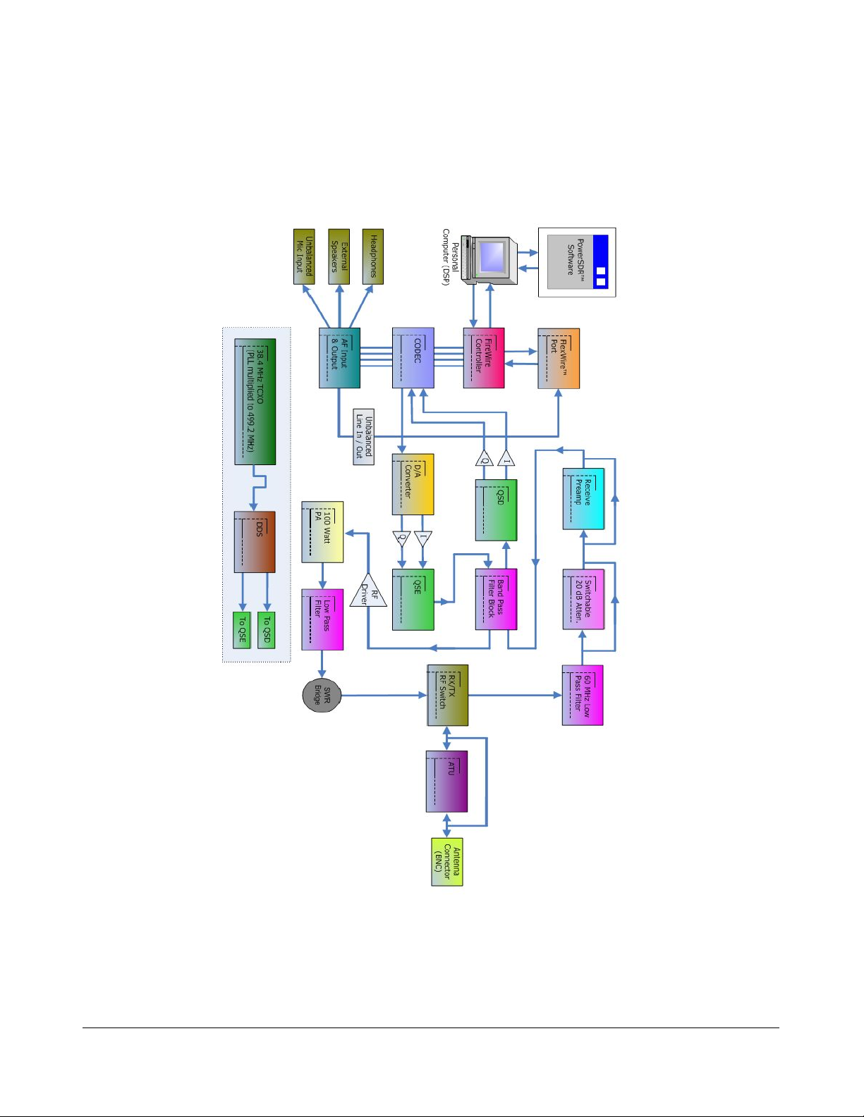
FLEX-3000 Architecture
The FLEX-3000 architecture is shown in Figure 5 below.
Figure 5: FLEX-3000 Architecture
F3K-M2.0/4 10 2003-2010 FlexRadio Systems

H A R D W A R E I N S T A L L A T I O N C H A P T E R 1
Declarations of Conformity
FCC
The FLEX-3000 complies with FCC Part 97 rules for the Amateur Radio Service.
EU Compliance
Signature on file at
FlexRadio Systems
F3K-M2.0/4 11 2003-2010 FlexRadio Systems

Chapter
2
Software Installation
Switch Off the FLEX-3000 and Install the FireWire Driver
Note 1: To install the software, you must at least connect the FLEX-3000 to a
13.8 VDC power supply and an IEEE 1394 FireWire computer port.
Note 2: If there is a (Edirol FA-66 or Presonus Firebox) sound card connected
to the same FireWire host controller you are planning to use with the
FLEX-3000, disconnect it until the installation is complete and the
FLEX-3000 is fully operational.
WARNING! It has been reported that data corruption occurred when
trying to use a FireWire hard disk. We do not recommend that
you have a FireWire hard disk connected to the same FireWire
controller (bus) as the FLEX-3000. Both of these devices use
the FireWire bus extensively and performance of both will be
degraded significantly.
Also, do not connect both a FLEX-3000 and a FLEX-5000 to the
same computer. The drivers cannot differentiate between the
two and erratic behavior may occur.
Make sure the FLEX-3000 is turned off (Power switch LED is not illuminated, see Figure 2 on page
3). Alternatively, disconnect the FireWire cable between your FLEX-3000 and the computer. It is also a
good idea to close all other applications.
All the software required for the FLEX-3000 is installed through the PowerSDR Setup application.
[The rest of this page has been left blank intentionally]
F3K-M2.0/4 13 2003-2010 FlexRadio Systems

S O F T W A R E I N S T A L L A T I O N C H A P T E R 2
Navigate to the home page of our website (http://www.flex-radio.com), locate the table of Current
Versions of Software and Documentation and click on the appropriate link to download the PowerSDR
Setup Application. The PowerSDR Setup Application runs the PowerSDR InstallShield Wizard which will:
1. Collect your information.
2. Start the FlexRadio Driver Setup Wizard to install the FireWire driver.
3. Install PowerSDR.
Collecting Your Information
Double click the downloaded application to start the InstallShield Wizard (Figure 61).
Figure 6: FlexRadio InstallShield Wizard - Welcome
Click Next to see the Proprietary Software License Agreement (Figure 7).
[The rest of this page has been left blank intentionally]
1
All screenshots in this manual are as they would appear when using the Microsoft Windows XP operating system and may look
slightly different when using Windows Vista or Windows 7, but the steps are the same.
F3K-M2.0/4 14 2003-2010 FlexRadio Systems

S O F T W A R E I N S T A L L A T I O N C H A P T E R 2
Figure 7: FlexRadio InstallShield Wizard – Proprietary Software License
There are two license agreements. The first is this End User License Agreement (EULA) for FlexRadio
proprietary software, which covers those parts of the software that are proprietary to FlexRadio
Systems. Read the agreement and select I accept the terms of the license agreement to
continue. Click Next to see the GNU Public License (Figure 8).
[The rest of this page has been left blank intentionally]
F3K-M2.0/4 15 2003-2010 FlexRadio Systems

S O F T W A R E I N S T A L L A T I O N C H A P T E R 2
Figure 8: FlexRadio InstallShield Wizard – GNU Public Software License
The second EULA refers to those parts of the software which are covered by the GNU Public License.
Reade the EULA and select I accept the terms of the license agreement to continue. Click Next to
enter your information (Figure 9).
[The rest of this page has been left blank intentionally]
F3K-M2.0/4 16 2003-2010 FlexRadio Systems

S O F T W A R E I N S T A L L A T I O N C H A P T E R 2
Figure 9: FlexRadio InstallShield Wizard – Customer Information
Enter you information and click Next to select the setup type (Figure 10).
[The rest of this page has been left blank intentionally]
F3K-M2.0/4 17 2003-2010 FlexRadio Systems

S O F T W A R E I N S T A L L A T I O N C H A P T E R 2
Figure 10: FlexRadio InstallShield Wizard – Setup Type
Select Complete to install all the software1. Click Next to select the radio(s) (Figure 11).
[The rest of this page has been left blank intentionally]
1
Only rarely will you need to select Custom and then select those parts of the software you wish to install.
F3K-M2.0/4 18 2003-2010 FlexRadio Systems

S O F T W A R E I N S T A L L A T I O N C H A P T E R 2
Figure 11: FlexRadio InstallShield Wizard – Radio Selection
Select FLEX-3000/5000 to install the software it requires. You may also elect to install at the same
time the software for any other FlexRadio Systems radio(s) you own. Click Next and the InstallShield
Wizard will indicate that it is ready to install (Figure 12).
[The rest of this page has been left blank intentionally]
F3K-M2.0/4 19 2003-2010 FlexRadio Systems

S O F T W A R E I N S T A L L A T I O N C H A P T E R 2
Figure 12: FlexRadio InstallShield Wizard – Ready to Install
To review and/or change your installation settings, click Back. Otherwise, click Install and the
InstallShield Wizard will proceed to install the FireWire Driver.
Installing the FireWire Driver
Before the FlexRadio FireWire Driver can be installed your radio must be turned off. You will see a
reminder to check that it is. (Figure 13).
Figure 13: FlexRadio InstallShield Wizard - Reminder to Turn Off Radio
Make sure your radio is indeed turned off and click Continue. The FlexRadio InstallShield Wizard will
start the FlexRadio Driver Setup Wizard and you will see a Welcome screen (Figure 14).
F3K-M2.0/4 20 2003-2010 FlexRadio Systems

S O F T W A R E I N S T A L L A T I O N C H A P T E R 2
Figure 14: FlexRadio Driver Setup Wizard - Welcome
Click Next to select the destination folder for the Driver (Figure 15).
[The rest of this page has been left blank intentionally]
F3K-M2.0/4 21 2003-2010 FlexRadio Systems

S O F T W A R E I N S T A L L A T I O N C H A P T E R 2
Figure 15: FlexRadio Driver Setup Wizard - Destination Location
The driver will be installed in the default location shown. Although we recommend you accept this
default location, you may change it; click Browse and Navigate to an alternative location. When done,
click Next to select additional Tasks (Figure 16).
[The rest of this page has been left blank intentionally]
F3K-M2.0/4 22 2003-2010 FlexRadio Systems
S O F T W A R E I N S T A L L A T I O N C H A P T E R 2
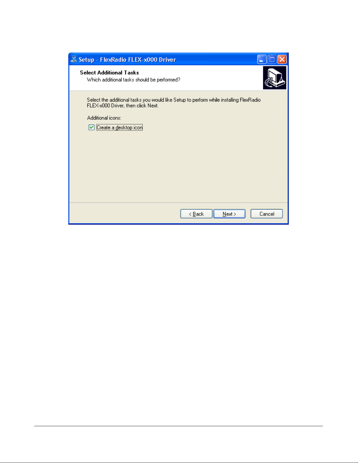
Figure 16: FlexRadio Driver Setup Wizard - Additional Tasks
We recommend that you elect to Create a desktop icon as shown for easy access to the Driver's Control
Panel. Select Next and the Wizard will now display that it is Ready to Install (Figure 17).
[The rest of this page has been left blank intentionally]
F3K-M2.0/4 23 2003-2010 FlexRadio Systems

S O F T W A R E I N S T A L L A T I O N C H A P T E R 2
Figure 17: FlexRadio Driver Setup Wizard - Ready to Install
To review and/or change your installation settings, click Back. Otherwise, click Install and the Driver
Setup Wizard will proceed to install all the required software (Figure 18).
[The rest of this page has been left blank intentionally]
F3K-M2.0/4 24 2003-2010 FlexRadio Systems

S O F T W A R E I N S T A L L A T I O N C H A P T E R 2
Figure 18: FlexRadio Driver Setup Wizard - Installing
While the software is installing the Driver Setup Wizard will display a progress bar. If a Software
Installation warning appears, click Continue Anyway to proceed. When completed, the Driver
Installation Wizard will indicate that it has successfully installed the Driver (Figure 19).
[The rest of this page has been left blank intentionally]
F3K-M2.0/4 25 2003-2010 FlexRadio Systems

S O F T W A R E I N S T A L L A T I O N C H A P T E R 2
Figure 19: FlexRadio Driver Setup Wizard - Installation Complete
Click Finish to exit the FlexRadio Driver Setup Wizard.
[The rest of this page has been left blank intentionally]
F3K-M2.0/4 26 2003-2010 FlexRadio Systems

S O F T W A R E I N S T A L L A T I O N C H A P T E R 2
Installing PowerSDR
The FlexRadio Systems InstallShield Wizard will now continue by installing PowerSDR (Figure 20).
Figure 20: FlexRadio InstallShield Wizard – Installing
While the software is installing, which may take several minutes, the InstallShield Wizard will display a
progress bar. When completed you will see a screen requesting you to turn on your radio 30-60
seconds after restarting your computer (Figure 21).
Figure 21: FlexRadio InstallShield Wizard - Notice to Power-Up Radio After Reboot
Click OK and the FlexRadio InstallShield Wizard will indicate that Installation is Complete (Figure 22).
F3K-M2.0/4 27 2003-2010 FlexRadio Systems

S O F T W A R E I N S T A L L A T I O N C H A P T E R 2
Figure 22: FlexRadio InstallShield Wizard – Installation Complete
Click Finish to exit the FlexRadio InstallShield Wizard. You will then be instructed to restart your
computer (Figure 23).
Figure 23: Instruction Restart Computer
Click Yes to restart your computer now.
Power Up the FLEX-3000 to Complete the Installation
After your computer has restarted, wait at least 30-60 seconds and then press and latch the power
button on the FLEX-3000 to power it up. After a brief moment, you will hear the power relay click and
the LED will illuminate the power button. What happens next depends on which operating system you
are using:
F3K-M2.0/4 28 2003-2010 FlexRadio Systems
S O F T W A R E I N S T A L L A T I O N C H A P T E R 2
Windows Vista and Windows 7
Windows will indicate that it recognizes the FLEX-3000 and will load the drivers in the background.
Please allow this process to finish. This will take between 10-30 seconds to complete. To ensure driver
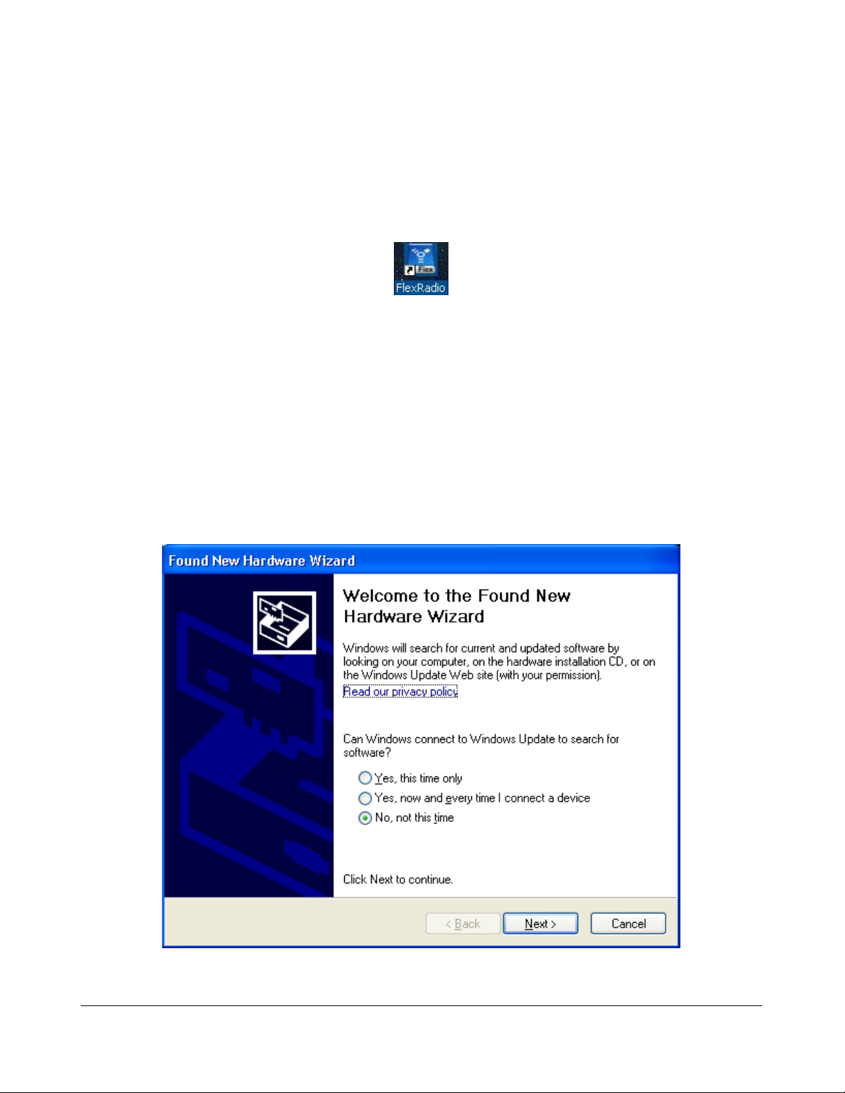
loading is indeed complete, open the FlexRadio Driver Control Panel by clicking on its icon (Figure 24)
on your desktop and verify that the Device Description is a FlexRadio Systems FLEX-3000.
Figure 24: FireWire Driver Icon
You are now ready to setup and configure PowerSDR (see page 33).
Windows XP
Three drivers will be loaded in succession: first the FlexRadio FLEX-3000, followed twice by the
FlexRadio MIDI. We will describe in detail how to proceed for the FlexRadio FLEX-3000. These steps are
identical for each of the other two.
Your computer will detect the FLEX-3000 (or FLEX-MIDI as the case may be) and display the Found
New Hardware Wizard Welcome screen (Figure 25).
Figure 25: Found New Hardware Wizard
F3K-M2.0/4 29 2003-2010 FlexRadio Systems

S O F T W A R E I N S T A L L A T I O N C H A P T E R 2
Select the option No, not this time and click Next to choose how to install the driver (Figure 26).
Note: Figure 25 may not show up in some systems.
Figure 26: Found New Hardware Wizard - Installing the FLEX-3000 Software
The Found New Hardware Wizard will show that you are trying to install a FlexRadio Systems FLEX-
3000. Select the option Install the software automatically (Recommended). Click Next to
continue.
The Found New Hardware Wizard will request you to please wait while it installs the software. If a
Hardware Installation warning appears, click the Continue Anyway button to proceed.
When the driver is loaded, the Found New Hardware Wizard will indicate that Installation is Complete
(Figure 27).
[The rest of this page has been left blank intentionally]
F3K-M2.0/4 30 2003-2010 FlexRadio Systems

S O F T W A R E I N S T A L L A T I O N C H A P T E R 2
Figure 27: Found New Hardware Wizard - Software Installation Complete
Click Finish to exit the Wizard.
As previously mentioned, the Found New Hardware Wizard will again be displayed, but now for the
FlexRadio MIDI. Follow the same steps as previously to install the MIDI driver. And finally, the Found
New Hardware Wizard will display one more time, again for the FlexRadio MIDI. Follow the same steps
as previously to install the MIDI driver. You are now ready to setup and configure PowerSDR.
[The rest of this page has been left blank intentionally]
F3K-M2.0/4 31 2003-2010 FlexRadio Systems

Chapter
3
PowerSDR Setup & Configuration
Setup Wizard
Power up the FLEX-3000 and start up the PowerSDR application using the shortcut on your Desktop (or
click on Start All Programs FlexRadio Systems FlexRadio Systems Software 2.n
PowerSDR v2.n.n). When you run a new release of PowerSDR for the first time an optimization routine
will run and the screens shown in Figure 28 will appear.
Figure 28: Optimization Routine
Click OK and let the routine run.
[The rest of this page has been left blank intentionally]
F3K-M2.0/4 33 2003-2010 FlexRadio Systems

P O W E R S D R S E T U P & C O N F I G U R A T I O N C H A P T E R 3
Note: This routine aims to optimize the FFT (Fast Fourier Transform)
calculations for the environment (hardware and software) in which the
calculations will be performed. For optimal performance, you should
therefore close all applications you will normally not be running
simultaneously with PowerSDR. The results are saved in a file called
wisdom in the %appdata%\FlexRadio Systems\PowerSDR v2.n.n1
directory. If you wish to run FFTW again, delete this file from that
directory and start up PowerSDR.
PowerSDR next transfers your FLEX-3000's calibration data to your computer. This only happens once,
the first time you run a new release of PowerSDR.
When the routine has completed, a brief startup sequence will follow, after which a warning regarding
mobile operation appears, as shown in Figure 29.
Figure 29: PowerSDR Setup Wizard Mobile Warning
Read the warning and then click the Continue button. The PowerSDR Setup Wizard will then ask you
to chose your Radio Model (Figure 30).
[The rest of this page has been left blank intentionally]
1
You can find your Application Data (%appdata%) directory by clicking StartRun in Windows and entering %appdata%
F3K-M2.0/4 34 2003-2010 FlexRadio Systems

P O W E R S D R S E T U P & C O N F I G U R A T I O N C H A P T E R 3
Figure 30: PowerSDR Setup Wizard - Radio Model
Select the FLEX-3000 radio model as shown in Figure 30. Click the Next button to continue to Figure
31.
Note: If you are running without a radio, e.g. for demonstration purposes,
select Demo/None.
[The rest of this page has been left blank intentionally]
F3K-M2.0/4 35 2003-2010 FlexRadio Systems

P O W E R S D R S E T U P & C O N F I G U R A T I O N C H A P T E R 3
Figure 31: PowerSDR Setup Wizard – Finished
The Setup Wizard is now complete. Click the Finish button to complete the wizard.
Note: If you forgot to power up the FLEX-3000 before starting PowerSDR, a
communication error message will be displayed and PowerSDR will
offer the ability to start in demo mode. Click No to close PowerSDR,
power up the FLEX-3000 and restart PowerSDR.
[The rest of this page has been left blank intentionally]
F3K-M2.0/4 36 2003-2010 FlexRadio Systems

P O W E R S D R S E T U P & C O N F I G U R A T I O N C H A P T E R 3
Configuration
Before operating the FLEX-3000 you will need to configure the Mixer. If you have not yet done so, start
up PowerSDR to open the Front Console, but do not yet click on the Start button.
Note: From time to time the FLEX-3000 firmware may need to be updated.
If PowerSDR detects an incompatible version of the firmware, it will
display an error message similar to that shown in Figure 32 below.
Figure 32: FLEX-3000 Firmware Version Error
Click OK and if a Driver Error message follows, click OK again.
PowerSDR will start up, but the Start button will be grayed out. Close
PowerSDR and see the Firmware Loader section on page 163. You
also might want to search for firmware in our Knowledge Center at
http://kc.flex-radio.com/search.aspx, locate the appropriate
document explaining how to upload the firmware and follow the
instructions.
Transfer of Calibration Data
When started for the first time, PowerSDR transfers your radio's calibration data from its EEPROM to
your computer. You will see the progress indicator shown in Figure 33. When the transfer is complete,
PowerSDR will complete starting up.
Figure 33: Calibration Retrieval Progress Indicator
[The rest of this page has been left blank intentionally]
F3K-M2.0/4 37 2003-2010 FlexRadio Systems

P O W E R S D R S E T U P & C O N F I G U R A T I O N C H A P T E R 3
Note: The FLEX-3000 comes to you completely factory calibrated. If due to
some unlikely event you suspect your radio needs to be recalibrated,
please contact FlexRadio Support, (on our Website, select About
FlexRadio and then Contact Us) who will guide you through the
process.
Audio Mixer
The FLEX-3000 input and output audio channels are managed with an audio mixer, much the same as
for your Windows sound card(s). To configure the audio mixer, click on Mixer on the Front Console
menu (Figure 34).
Figure 34: Audio Mixer
Select the desired Input and Output channels. Only one Input channel can be selected, but multiple
Output channels can be selected. Mic and Head Phones are front panel jacks; the other channels
refer to the various audio inputs and outputs on the back panel. For more detailed information see
page 100).
Ready to Start Operating
You are now ready to use your FLEX-3000. Click on Start on the Front Console and you should hear
receive audio. If you do not, double check all your connections and settings (especially for the Mixer
and Antenna forms).
We urge you to read the remainder of this manual to help you fully understand the FLEX-3000 and
PowerSDR. This will enable you to optimize your radio for your personal operating style and
environment. You may also want to visit our extensive and ever expanding Knowledge Center
(http://kc.flex-radio.com/search.aspx) for more detailed and more up-to-date information on many
topics.
F3K-M2.0/4 38 2003-2010 FlexRadio Systems

Chapter
4
Operation
This chapter is intended to provide the user with a clear understanding of how the FLEX-3000 should be
used when performing basic operations such as Powering Up or making a voice, CW or digital
transmission.
Note 1: For consistency we will use the same control identifiers as used in
Figure 44 on page 59. For clarity we will leave out any identifiers of
controls not referenced in the relevant section.
Note 2: We assume you have familiarized yourself with the FLEX-3000
hardware and its many connections, have installed and initialized the
FLEX FireWire driver and have installed and configured PowerSDR. If
not, please see the previous chapters.
Note 3: If you have any questions, issues or problems operating PowerSDR
and/or the FLEX-3000, you may be able to find the solution on the
Support Pages (http://support.flex-radio.com/) of our website, in our
Knowledge Center (http://kc.flex-radio.com/search.aspx), or through
our highly active Reflectors. (search for reflector on our Knowledge
Center at http://kc.flex-radio.com/search.aspx). If none of these
sources provide you the assistance required, please contact FlexRadio
Systems using the information provided on the Contact page of our
website (on our website www.flex-radio.com click About FlexRadio
and then Contact Us).
[The rest of this page has been left blank intentionally]
F3K-M2.0/4 39 2003-2010 FlexRadio Systems

O P E R A T I O N C H A P T E R 4
Power-Up Procedure
To power up the FLEX-3000
1. Connect (at a minimum) the FLEX-3000 to the computer and the power supply. Check the
connections to ensure good contact.
2. Boot up the computer and make sure PowerSDR is ready to be launched (no hour glass
cursor), but do not start it yet.
3. Turn on the power supply for the radio and press the FLEX-3000 power switch to latch it in the
on position. After a few seconds you will hear the internal power relay click and see the LED
illuminate. The FLEX-3000 will be recognized by Windows and its driver will be available for
PowerSDR to use.
4. After waiting at least 30 seconds, start up PowerSDR. It will automatically recognize the FLEX3000 driver. You are now ready to operate.
Power-Down Procedure
The power-down sequence is almost the reverse of the power-up procedure.
1. Stop PowerSDR by clicking on the Start/Stop button.
2. Close PowerSDR by clicking on the “X” in the upper right hand corner of the Front Console.
3. Press the FLEX-3000 illuminated Power switch to unlatch it and turn off the transceiver.
CAUTION: Make sure PowerSDR is shut-down before turning off the radio. Failing
to do so may result in instability of your computer system, leading to
a Blue Screen.
[The rest of this page has been left blank intentionally]
F3K-M2.0/4 40 2003-2010 FlexRadio Systems

O P E R A T I O N C H A P T E R 4
Tuning Methods
Spectrum Drag and Click
The easiest way to tune signals on the display when set to Panadapter or Waterfall is simply to click on
the signal and drag it into the filter area. You can also drag the displayed filter edges to adjust the filter
width as well.
Mouse Wheel
A mouse wheel is the another easy way to tune the radio. While the PowerSDR window is active, tune
VFO A using the mouse wheel, with the mouse cursor anywhere on the screen. The frequency will
change in steps equal to the selected Tune Step (2)1 for each click of the mouse wheel. Adjust the
Tune Step using the controls(+ and – buttons), clicking the mouse wheel or pressing Ctrl + Left or
Right Arrow key.
Note: When the Tune Step equals 1 kHz, each click of the mouse wheel will
first snap tune up or down to the nearest 1 kHz and then change in
1 kHz steps. E.g. if VFO A is tuned to say 14.000258 MHz then with
the tuning rate set to 1 kHz, using the mouse wheel to tune up will
first increase VFO A to 14.001000 MHz and then to 14.002000 MHz,
and so on.
Hint: Holding down the Shift key while turning the mouse wheel will change
VFO A at the next lower Tune Rate.
Mouse Wheel Hover
Hover with the mouse over a digit in either VFO A or VFO B and increase or decrease its value using
the mouse wheel. The digit to be tuned will be underlined.
Spectrum Click Tuning
With the display set to Spectrum, Panadapter, Waterfall or Histogram, hover with the mouse over the
display and right click to cycle through yellow cross-hairs to tune VFO A, red cross-hairs to tune VFO B
(only if VFO B is active, e.g. when SPLT (12) and/or MultiRX (10) are activated), or no cross-hairs
(click tuning off). With the cross-hairs visible, hover over the desired signal in the display and click the
left mouse button. The corresponding VFO will immediately tune to the frequency of the selected
signal.
When in CW, AM, SAM, DSB, FM, or DRM the VFO will tune the cursor frequency to the center of the
filter pass band. In SSB the VFO will tune to the carrier frequency for the sideband selected.
1
Chapter 5 on page 59 explains all the Front Console controls in detail. The identifiers between parentheses refer to the control
identifiers used there.
F3K-M2.0/4 41 2003-2010 FlexRadio Systems

O P E R A T I O N C H A P T E R 4
Hint 1: You can very quickly center a CW, (S)AM, DSB or FM signal after click
tuning it by clicking the 0 Beat (12) button on the Front Console
(make sure the display AVG (9) button is on to enable 0 Beat).
Hint 2: If you have checked Snap Click Tune (Setup Form, General tab -
Options sub-tab; see page 110) then spectrum click tuning will tune
the VFO to the nearest discrete multiple of the Tune Step. E.g. if the
Tune Step is set to 1 kHz, the VFO will only Click Tune in steps of
1 kHz.
Keyboard Keys
Use the following keys on your keyboard to tune the VFO.
Numeric Keypad : Key any frequency in MHz (e.g. 7.250) into the numeric keypad and hit
enter to immediately tune VFO A to that frequency.
Mapped Keys : You can map keys on your keyboard to tune each of the digits in VFO A using
the Keyboard Tab on the Setup Form (page 149).
Ctrl +Arrow Keys : Hold the Control key and press the
o Up or Down Arrow key to tune VFO A up or down by the Tune Step (2).
o Right or Left Arrow key to increase or decrease the Tune Step (2).
USB Tuning Knob
Both the Griffin PowerMate and the Contour Designs Shuttle Pro v2 can be used to tune the radio. You
can download the Griffin PowerMate Quick Start Guide and the Contour ShuttlePro v2 Quick Start
Guide from the downloads page of our website to learn how to setup and use these controllers. Also
available is the Contour ShuttlePro Default Preferences file, which can be imported as a good starting
point when using this controller. (All these documents and more can be found by searching for either
PowerMate or ShuttlePro on our Knowledge Center at http://kc.flex-radio.com/search.aspx)
[The rest of this page is intentionally left blank]
F3K-M2.0/4 42 2003-2010 FlexRadio Systems

O P E R A T I O N C H A P T E R 4
Voice Operation
The following procedure outlines how to setup quickly for voice transmission operation (SSB, AM, or
FMN). If something in this procedure is unclear, please contact us, as we would like this to be as simple
as possible.
Figure 35 Front Panel Controls Used for Basic Voice Operation.
Please use Figure 351 to identify the controls referenced in the following step-by-step instruction. For
consistency we have used the same control identifiers as in Figure 44 on page 59 and for clarity we
have left out any identifiers of controls not referenced.
Note: In this chapter, we will only describe basic operation
[The rest of this page has been left blank intentionally]
1
All screenshots of the Front Console are displayed with the Default skin. Your Front Console may look differently if you have
selected a different skin (see page Error: Reference source not found for more information on how to select skins).
F3K-M2.0/4 43 2003-2010 FlexRadio Systems

O P E R A T I O N C H A P T E R 4
1. Follow the Power Up Procedure, described on page 40. Then click the Start/Stop button (14).
Set the following controls as specified in Table 6 below.
Table 6: Initial Control Values for Voice Operation
Reference to
Ctrl Value
VFO A 14.3 MHz (1)
RX Meter Signal (4)
TX Meter MIC (4)
BAND 20 m (5)
Mode USB (6)
Filter 2.7 kHz (7)
Mic Gain 35 (8)
DX Off (8)
CPDR Off (8)
VOX Off (8)
GATE Off (8)
RX EQ Off (8)
TX EQ Off (8)
VAC Off (8)
Display Mode Panadapter (9)
AVG On (9)
PEAK Off (9)
MultiRX Off (10)
SPLT Off (12)
XIT Off (12)
RIT Off (12)
MUT Off (17)
AF 50 (21)
AGC-T 70 (22)
Drive 50 (23)
AGC Med (24)
RX Gain Pre (25)
SQL Off (26)
Figure 35
2. Connect a 50 Ohm dummy load to the antenna jack, or tune VFO A (1) to a quiet frequency
on the selected band. Use the TUN (19) button to verify power output on the TX Meter (4)
(Set to Fwd Pwr). If using the integrated ATU click the ATU (20) button to initiate a tuning
cycle.
CAUTION: If you are not using the internal ATU then connect a 50 ohm dummy
load, or ensure that the antenna presents a 50 ohm load with a low
SWR. Failing to do so may damage the FLEX-3000 output transistors.
F3K-M2.0/4 44 2003-2010 FlexRadio Systems

O P E R A T I O N C H A P T E R 4
3. Press the Push-to-talk button on the microphone or click the MOX (16) button and speak into
the microphone to transmit your voice. Release the Push-to-talk button or click the MOX (16)
button to switch the transceiver back to receive.
If you do not see modulation on the spectrum, please check that the correct input for your
microphone is selected in the Mixer Form (34) (see page 100) and that your microphone is
connected correctly (see page 4 for pin-outs of the MIC connector). If you are using any
external audio processing equipment, make sure it is turned on and hooked up correctly. Finally,
if your audio level seems very low, you might try checking Mic Boost On on the Setup form –
Audio tab, primary sub-tab (see page 115).
4. Now that you can see the modulation on the spectrum, it is time to adjust the input. While
transmitting, monitor the values with the TX Meter (4) set to Mic. Modify the MIC Gain (8)
setting until the TX Meter shows 0 dB on peaks while talking in a normal voice at a normal
distance from the microphone (above 0 dB the signal will be compressed).
5. You are now ready to begin a QSO. If a 50 ohm dummy load was connected, connect an
antenna in its place. Tune to the desired frequency using one of the methods outlined in the
Tuning Methods section above.
Use the Mode Specific Controls – Phone (8) including DX, CPDR, VOX and (Noise) Gate.
Generally, use either DX or CPDR to increase average power without adjusting the peaks. Check
Show Transmit Filter on Display to visualize the band edges of the transmit filter. This filter can be
adjusted on the Transmit Tab of the Setup Form.
Hint: For information on how to optimize your audio further, please refer to
the Knowledge Center (http://kc.flex-radio.com/search.aspx) on
our website.
6. In order to monitor voice transmissions, enable the MON (15) button. You may notice a delay
due to buffering in the audio/DSP system. This processing delay is largest when using large
buffer sizes and low sampling rates. If you find this delay objectionable, try decreasing it by
reducing the Buffer Size and increasing the Sample Rate settings on the Audio tab, Primary
sub-tab (page 115) and/or DSP tab, Options sub-tab (page 124) of the Setup Form. Make sure
that when changing the Audio Buffer Size, you first Stop (14) PowerSDR and make the same
change in the FLEX-3000 Driver (see page Error: Reference source not found) before Starting
PowerSDR again. See also the Knowledge Base article http://kc.flex-
radio.com/KnowledgebaseArticle50437.aspx for more information on Buffers and Sample Rate
and how they effect latency and filter skirts.
7. The Fwd Pwr setting on the TX Meter (4) will read out average power in Watts, measured at
the output of the internal Power Amplifier. While the average has a short time constant, it is still
an average and will not approach 100W in voice modes if calibrated properly even when the
Drive control (21) is set to 100. This is also true when monitoring voice transmissions on an
external watt meter.
[The rest of this page has been left blank intentionally]
F3K-M2.0/4 45 2003-2010 FlexRadio Systems

O P E R A T I O N C H A P T E R 4
Note: The typical male voice has a peak to average power ratio of 14 dB.
Therefore a typical male voice transmission that is peaking at 100W
will only average less than 10W. To raise the average power, use the
DX (8) control and the associated slider to increase the compression
in 1 dB steps. This must be done carefully and incrementally as
adding too much compression can result in high levels of distortion.
CW Operation
The following procedure outlines how to setup quickly for CW transmissions using the Internal Keyer
and paddles, an external keyer, the CWX-form or a third party program.
Figure 36: Front Panel Controls Used for CW Operation
Please use Figure 36 to identify the controls referenced in the following step-by-step instruction. For
consistency we have used the same control identifiers as in Figure 44 on page 59 and for clarity we
have left out any identifiers of controls not referenced.
[The rest of this page has been left blank intentionally]
F3K-M2.0/4 46 2003-2010 FlexRadio Systems

O P E R A T I O N C H A P T E R 4
Initial Settings
1. Follow the Power Up Procedure, described on page 40. Then click the Start button (14). Set
the following controls as specified in Table 7.
Table 7: Initial Control Values for CW Transmission
Reference to
Ctrl Value
VFO A 14.05 MHz (1)
RX Meter Signal (4)
TX Meter Fwd Pwr (4)
Band 20 m (5)
Mode CWU (6)
Filter 500 Hz (7)
VAC Off (8)
Display Mode Panadapter (9)
AVG On (9)
PEAK Off (9)
MultiRX Off (10)
SPLT Off (12)
XIT Off (12)
RIT Off (12)
MON On (15)
MUT Off (17)
AF 50 (21)
AGC-T 70 (22)
Drive 25 (23)
AGC Med (24)
RX Gain Pre (25)
SQL Off (26)
Figure 36
2. Connect a 50 ohm dummy load to the antenna jack, or tune VFO A (1) to a quiet frequency on
the selected band. Use the TUN (19) button to verify power output on the TX Meter (4) (Set
to Fwd Pwr). If using the integrated ATU click the ATU (20) button to initiate a tuning cycle.
CAUTION: If you are not using the internal ATU then connect a 50 ohm dummy
load, or ensure that the antenna presents a 50 ohm load with a low
SWR. Failing to do so may damage the FLEX-3000 output transistors.
[The rest of this page has been left blank intentionally]
F3K-M2.0/4 47 2003-2010 FlexRadio Systems

O P E R A T I O N C H A P T E R 4
Hint: There is a trade-off to be made of minimum latency versus sharpest
(narrowest) filters. Both are driven by the buffer (DSP and Audio)
settings and the sample rate setting. For optimal CW performance,
you may need to use the 48 kHz sample rate, which will give the
narrowest filters. Next you need to set your audio buffer as low as
your computer system will tolerate. The DSP buffer setting should
then be set as high as possible, without introducing disturbing latency.
See also the Knowledge Base article
http://kc.flex-radio.com/KnowledgebaseArticle50437.aspx for a more
detailed explanation of Buffers and Sample Rate.
Note: CW VFO Frequency Offset
The VFO in PowerSDR is designed to show the zero beat of the CW
tone relative to the selected CW Pitch. This allows click-tuning of CW
signals as well as the traditional CW VFO readout. This also enables
the VFO to remain constant when switching from CWL to CWU mode.
Every effort is made to preserve a CW signal when switching between
any SSB and CW modes.
Internal Keyer
If using PowerSDR’s internal keyer, open the Setup Form – DSP Tab, Keyer Sub-Tab shown in Figure 37
below. Several of the controls in this form are also available in the Mode Specific Controls – CW (8)
section on the Front Console.
[The rest of this page has been left blank intentionally]
F3K-M2.0/4 48 2003-2010 FlexRadio Systems
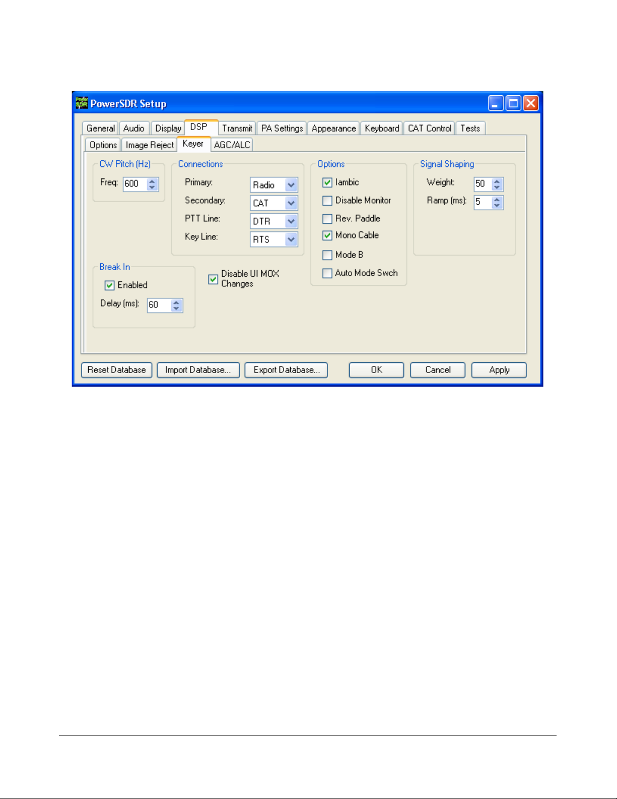
O P E R A T I O N C H A P T E R 4
Figure 37: Setup Form – DSP Tab, Keyer Sub-Tab
1. Connect your paddles or key to the Key jack on the front panel (see page 3) and on the Keyer
Sub-Tab in the Connections section, set Primary to Radio (see Figure 39 below).
2. In the Options section, check Iambic for Iambic mode, otherwise leave unchecked (e.g. for a
straight key). If the paddles seem reversed, check Rev. Paddle. If your key connector only has
a tip and shield (i.e. the cable is a mono cable), check Mono Cable; leave unchecked if the
connector has a tip, ring and shield. Check Disable UI MOX Changes to avoid delays due to
changes in the Front Console when switching between transmit and receive. (refer to the Keyer
Sub-Tab section on page 121 for more detail).
3. The Break In option allows the radio to start transmitting simply with detection of keyer input.
Set Delay to the amount of time between key up and when the radio will switch back to
receive.
4. Select the settings for CW Pitch, Weight and Ramp as desired (refer to the Keyer Sub-Tab
section on page 132 for more detail).
4. If not using Break In, click MOX (16) on the Front Console and begin transmitting using your
paddles. If using Break In (8), simply begin transmitting to key the radio. If using Iambic
mode, adjust the speed with CW Speed (8) on the Front Console. If Disable Monitor is
unchecked, you should hear the side tone. Verify with the TX Meter (4) set to Fwd Pwr that
there is forward power.
F3K-M2.0/4 49 2003-2010 FlexRadio Systems

O P E R A T I O N C H A P T E R 4
5. You are now ready to begin a QSO. If a 50 ohm dummy load was connected, connect an
antenna in its place. Tune to the desired frequency using one of the methods outlined in the
Tuning Methods section above. Select either CWL or CWU (6) and proceed with the QSO.
External Keyer
1. Connect your keyer to the Key jack on the front panel (see page 3) and set the Primary
Connection to Radio (see Figure 37 above)
2. In the Options section, leave Iambic unchecked. If your external keyer does not seem to be
keying, try checking Rev. Paddle. If using an external keyer with a side tone, check the
Disable Monitor check box to avoid hearing the side tone from the internal keyer. The Break
In option allows the radio to start transmitting simply with detection of keyer input. Set Delay
to the amount of time between key up and when the radio will switch back to receive.
3. If using the side tone from the internal keyer, select the settings for CW Pitch. Select the
settings for Weight and Ramp as desired (refer to the Keyer Sub-Tab section on page 132 for
more detail).
4. If not using Break In, click MOX (16) on the Front Console and begin transmitting using your
external keyer. If using Break In, simply begin transmitting to key the radio If Disable
Monitor is unchecked, you should hear the side tone. Verify with the TX Meter (4) set to Fwd
Pwr that there is forward power.
5. You are now ready to begin a QSO. If a 50 ohm dummy load was connected, connect an
antenna in its place. Tune to the desired frequency using one of the methods outlined in the
Tuning Methods section above. Select either CWL or CWU (6) and proceed with the QSO.
CWX Form
If you wish to send CW automatically, click on CWX (36) on the Front Console menu to open the
CWX Form shown in Figure 38 below. (Refer to the CWX Form section on page 95 for more detail
on how to use this form).
Figure 38: CWX Form
1. Click on one of the numbered buttons to start transmitting the corresponding CW sequence.
Verify with the TX Meter (4) set to Fwd Pwr that there is forward power.
F3K-M2.0/4 50 2003-2010 FlexRadio Systems

O P E R A T I O N C H A P T E R 4
2. You are now ready to begin a QSO. If a 50 ohm dummy load was connected, connect an
antenna in its place. Tune to the desired frequency using one of the methods outlined in the
Tuning Methods section above. Select either CWL or CWU (6) and proceed with the QSO.
Third Party CW Program
To operate CW with a third party program, traditionally the computer is connected to the radio through
a serial port. Although PowerSDR can also connect to a serial port, using third party CW software would
then require two serial ports interconnected through a null modem cable1. If the third party software
and PowerSDR are running on the same computer, this is not only somewhat cumbersome, it also
requires the computer to have two serial ports.
Alternatively, a virtual null-modem serial port pair can be created, as shown in Figure 39. There are
various programs that can be used to create such a virtual serial port pair, such as VSP Manager (see
http://k5fr.com/ddutilwiki/index.php?title=VSP_Manager) or Com0Com (search for com0com in our
Knowledge Center at http://kc.flex-radio.com/search.aspx). The key to understand is that virtual serial
ports present themselves to programs just like physical ports. Also, the pair consists of two virtually
interconnected ports (shown below as COM-A and COM-B). One of these ports is selected as the CAT
control port in PowerSDR, the other as the port to connect to in the CW program.
Figure 39: Diagram Illustrating Connections Between PowerSDR and Third Party Program
In the following we will assume that a virtual serial port pair COM6/COM26 has been created. (In other
words COM-A = COM26 and COM-B = COM6).
1. In PowerSDR open first the Setup Form, CAT Control tab, select COM26 as the Cat Control
port for PowerSDR to connect to and check Enable CAT (see page 150).
2. Next, in PowerSDR open the Setup Form – DSP Tab, Keyer Sub-Tab shown in Figure 40
below to access the Internal Keyer controls.
1
If the CW program runs on one computer and PowerSDR on another, two physical serial ports are indeed required (one on
each computer). The ports are interconnected as described.
F3K-M2.0/4 51 2003-2010 FlexRadio Systems

O P E R A T I O N C H A P T E R 4
Figure 40: Setup Form – DSP Tab, Keyer Sub-Tab
3. On the Keyer Sub-Tab in the Connections section, set Secondary to CAT (to use the virtual
COM port COM26), as selected on the CAT Control Tab. This will open up two additional
selection boxes. Set PTT Line to DTR and Key Line to RTS as shown above.
4. Finally, configure your CW program to use COM6 as its port, set PTT to operate via CAT and
connect CW to RTS and PTT to DTR. Set the transceiver type as a Kenwood
control commands of PowerSDR are based on those of the Kenwood TS2000 and have been
extended to cover PowerSDR’s many unique features; search for cat in our Knowledge Center at
http://kc.flex-radio.com/search.aspx for more information on the PowerSDR's CAT commands)
5. You are now ready to begin a QSO. If a 50 ohm dummy load was connected, connect an
antenna in its place. Tune to the desired frequency using one of the methods outlined in the
Tuning Methods section above. Select either CWL or CWU (6) and proceed with the QSO.
[The rest of this page has been left blank intentionally]
1
®
TS2000 (The CAT
1
Kenwood is a registered trademark of Kenwood Corporation
F3K-M2.0/4 52 2003-2010 FlexRadio Systems

O P E R A T I O N C H A P T E R 4
Digital Operation
Operating digital modes traditionally requires a sound card connection between the computer and your
transceiver for your digital mode software to decode and encode signals. Additionally, a serial port
connection can be used so that your digital mode program can control the transceiver.
Although PowerSDR can connect to a sound card, connecting to digital mode software would require a
second sound card, with both sound cards interconnected such that the output of one connects to the
input of the other and vice versa1. If the digital mode software and PowerSDR are running on the same
computer, this is not only somewhat cumbersome (two sound cards on one computer), the signals are
also converted from digital to analog and back to digital leading to loss of signal quality.
Instead, we can use a program called Virtual Audio Cable (VAC) to create virtual digital audio
connections, that present themselves to programs just like a sound card. For more information, search
for VAC in our Knowledge Center at http://kc.flex-radio.com/search.aspx. Likewise, for the serial port
interconnection, there are several programs that can be used to create a virtual null-modem serial port
pair. This is described in the previous section (see Third Party CW Program on page 51). Figure 41
below illustrates these virtual connections.
Figure 41: Virtual Audio and Serial Port Connections Between PowerSDR and Digital Program
In the following we will assume that two virtual audio cables (Virtual Cable 1 and Virtual Cable 2) have
been created as well as a virtual serial port pair COM6/COM26. (In other words COM-A = COM26 and
COM-B = COM6).
[The rest of this page has been left blank intentionally]
1
If the digital mode software and PowerSDR run on separate computers, two sound cards (one on each computer) are indeed
required and they are interconnected as described.
F3K-M2.0/4 53 2003-2010 FlexRadio Systems
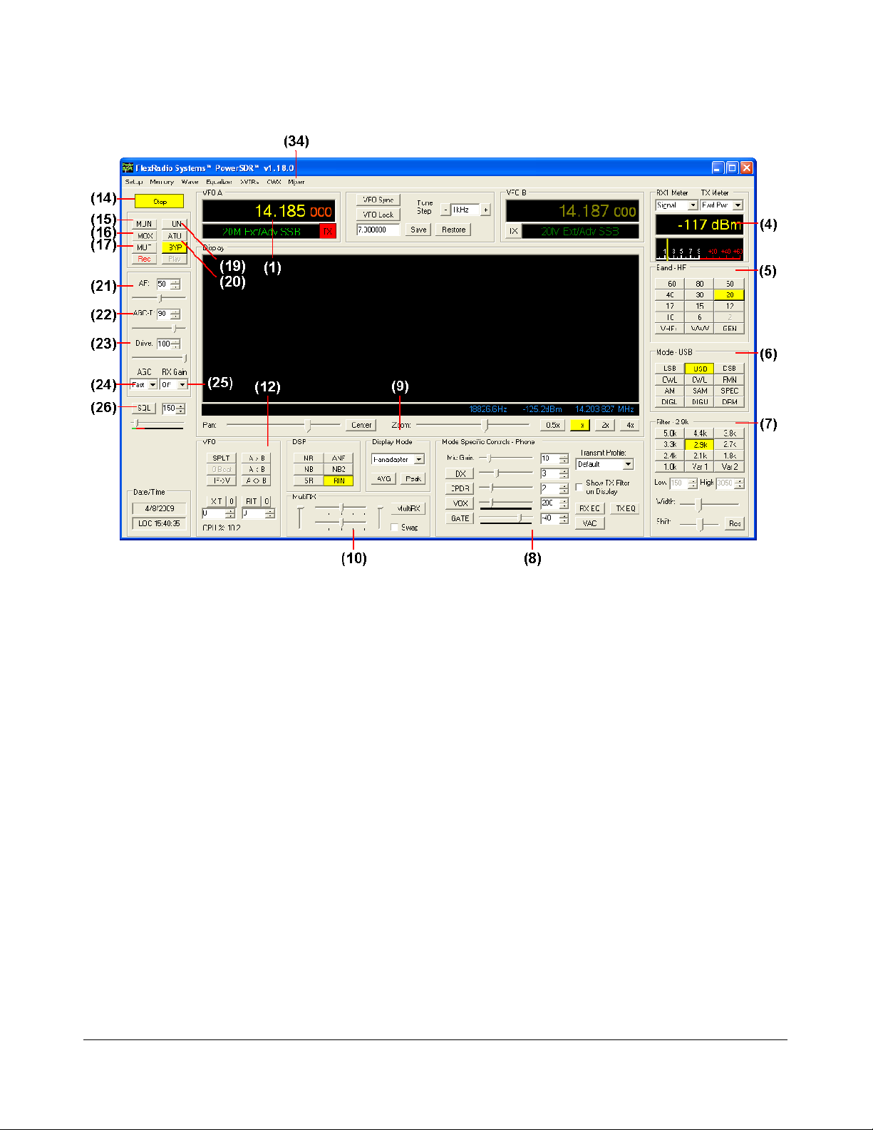
O P E R A T I O N C H A P T E R 4
Figure 42: Front Panel Controls Used for Basic Digital Mode Operation
Please use Figure 42 to identify the controls referenced in the following step-by-step instruction. For
consistency we have used the same control identifiers as in Figure 44 on page 59 and for clarity we
have left out any identifiers of controls not referenced.
[The rest of this page has been left blank intentionally]
F3K-M2.0/4 54 2003-2010 FlexRadio Systems

O P E R A T I O N C H A P T E R 4
1. Follow the Power Up Procedure, described on page 40. Then click the Start button (14). Set
the following controls as specified in Table 8.
Table 8: Initial Control Values for Digital Mode Operation
Reference to
Ctrl Value
VFO A 14.09 MHz (1)
RX Meter Signal (4)
TX Meter Fwd Pwr (4)
BAND 20 m (5)
Mode DIGU (6)
Filter 2.7 kHz (7)
VAC On (8)
Display Mode Panadapter (9)
AVG On (9)
PEAK Off (9)
MultiRX Off (10)
SPLT Off (12)
XIT Off (12)
RIT Off (12)
MUT Off (17)
AF 50 (21)
AGC-T 70 (22)
Drive 25 (23)
AGC Med (24)
RX Gain Pre (25)
SQL Off (26)
Figure 42
2. In PowerSDR open the Setup Form, Audio tab and then the VAC sub-tab (see Figure 43
below). Check Enable VAC, Select Virtual Cable 1 as the Input and Virtual Cable 2 as the
Output. If your digital mode software requires a stereo connection, check Stereo. To
automatically enable VAC for DIGU, DIGL and DRM (6) modes, check Auto Enable. When
operating these modes, the Front Console also shows several controls relating to VAC (8), as
shown in Figure 42 above).
3. If you want your digital mode software to control PowerSDR, then in the Setup Form - CAT
Control tab, select COM26 as the Cat Control port for PowerSDR to connect to and check
Enable CAT (see page 151).
[The rest of this page has been left blank intentionally]
F3K-M2.0/4 55 2003-2010 FlexRadio Systems

O P E R A T I O N C H A P T E R 4
Figure 43: Setup Form - Audio Tab ,VAC Sub-Tab
4. Start up your digital mode program, select Virtual Cable 1 for its sound card output and Virtual
Cable 2 for its input. Use the RX Gain (8) control to adjust the audio level going to your digital
mode program (instead of the AF (21)) and TX Gain (8) to adjust the level going to
PowerSDR.
5. If you are controlling PowerSDR with your digital mode software, set its CAT port to COM6.
6. Connect a 50 ohm dummy load to the antenna jack, or tune VFO A (1) to a quiet frequency on
the selected band. Use the TUN (19) button to verify power output on the TX Meter (4) (Set
to Fwd Pwr). If using the integrated ATU click the ATU (20) button to initiate a tuning cycle.
CAUTION: If you are not using the internal ATU then connect a 50 ohm dummy
load, or ensure that the antenna presents a 50 ohm load with a low
SWR. Failing to do so may damage the FLEX-3000 output transistors.
7. If using CAT control, click on the Transmit button of your digital mode program. It should switch
PowerSDR to transmit. Transmit a test signal (e.g. several CQ calls) in the mode you plan to
operate and use the TX Gain (8) control to adjust the volume of audio coming from your
digital mode program. Set the TX Meter (4) to ALC and adjust for 0 dB to calibrate transmit.
Click on Receive on your digital mode program and PowerSDR should switch back to receive.
F3K-M2.0/4 56 2003-2010 FlexRadio Systems

O P E R A T I O N C H A P T E R 4
8. You are now ready to begin a QSO. If a 50 ohm dummy load was connected, connect an
antenna in its place. Tune to the desired frequency using one of the methods outlined in the
Tuning Methods section above. Select either DIGL or DIGU (6) for lower or upper side band
digital mode operation respectively. Select DRM (6) for DRM mode operation.
Note 1: The DIGL, DIGU and DRM (6) mode buttons bypass all signal
processing in PowerSDR, except for AGC and Filtering. With DIGL and
DIGU you have control over the filter width using the filter buttons
(7). DRM mode invokes a fixed 10 kHz wide double side band filter.
Note 2: DIGL and DIGU (6) apply an offset when using Spectrum Click
Tuning (see page 110). By default, the offsets are set to 1200 Hz
(SSTV) in DIGU mode and 2210 Hz (RTTY) in DIGL mode
respectively. These offsets can be modified on the Setup Form -
General Tab, Options Sub-Tab.
Separately, so called RTTY Offsets (for DIGU and DIGL mode) can
be applied to the VFO A (and/or VFO B) frequency, before CAT
reports it to a third party program (see page 150). These offsets can
be modified on the Setup Form – CAT Control Tab.
Hint 1: When operating digital modes you have two options with regard to
using filters. On the one hand you can use a wide band-pass filter in
PowerSDR and use the filters within your digital mode program for
selectivity.
On the other hand you can home in on a specific signal with
PowerSDR’s filters and ignore the filters in your digital mode program.
Although circumstances and operator preference will dictate which to
use, many operators have found the second option to be especially
valuable to them.
Hint 2: Please check our Knowledge Center (http://kc.flex-
radio.com/search.aspx) for more articles on how to use PowerSDR
with various digital mode programs.
[The rest of this page has been left blank intentionally]
F3K-M2.0/4 57 2003-2010 FlexRadio Systems

Front Console
Chapter
5
Figure 44: FLEX-3000 PowerSDR 1.18.0 Front Console
Note: The front console controls the basic functions of the radio: frequency,
mode, filters, and display. In addition to these basic features, there
are many other controls that are described in detail below. The exact
behavior of many of these controls can be configured with the Setup
Form.
Hint 1: Hovering with your mouse over any control will show a brief
description of that control’s function.
F3K-M2.0/4 59 2003-2010 FlexRadio Systems

F R O N T C O N S O L E C H A P T E R 5
Hint 2: Clicking just to the left or right of a slider will respectively decrease or
increase its value by 1.
(1) VFO A
Figure 45: VFOA
VFO A is the main tuning VFO. It consists of a frequency and a band description (related to the selected
frequency). The upper frequency area of the VFO is a Text Box and may be edited as such (click and
drag highlighting, etc). The frequency may also be changed by entering a numeric character (without
any mouse interaction). An underline will indicate the digit that will be tuned when hovering over the
frequency display. See the Tuning Methods on page 41 for more details on how to tune. Note that
when using the keyboard to enter a frequency, you can return to the previous frequency at any time by
pressing the ‘Escape’ (Esc) key before you press the Enter key.
The red TX indicator identifies which VFO is displaying the transmit frequency:
With Split off, the transmit frequency is displayed in VFO A (VFO A TX indicator is red)
With Split on, the transmit frequency is displayed in VFO B (VFO B TX indicator is red).
The band text information below the frequency gives general information about the FCC Amateur
bands as well as the Short Wave Radio bands and WWV. If not on a recognized frequency, the text will
display “Out Of Band”. If not in an amateur band, the text background will change from black to gray.
Note that this information has no bearing on the current operating mode.
(2) Tuning Controls
Figure 46: Tuning Controls
VFO Sync keeps VFO B synchronized to VFO A.
VFO Lock keeps the frequency from being changed inadvertently. This is a handy feature to use while
in a QSO to keep from accidentally losing the frequency due to clicking in the wrong area or hitting the
wrong key on the keyboard.
F3K-M2.0/4 60 2003-2010 FlexRadio Systems

F R O N T C O N S O L E C H A P T E R 5
The Tune Step displays the current tuning rate when using the mouse wheel (or Ctrl + Up/Down
Arrow) to tune the radio. Rotating the mouse wheel away from you will increase the frequency with the
tune step for each click, while rotating the wheel toward you will decrease the frequency. You can
change the Tune Step by clicking either of the – or + buttons, clicking the mouse wheel button, or
using Ctrl + Left/Right Arrow.
The Save button quickly saves the frequency, mode and filter. The saved frequency is shown in the box
to its left. The Restore button restores the most recently saved frequency (displayed), mode and filter.
(3) VFO B
Split Transmit Frequency MultiRX Frequency
Figure 47: VFO B
The operation of VFO B is similar to that of VFO A. However, VFO B is used only in specific instances:
When operating split (SPLT button), VFO B displays in red the transmit frequency (and TX
indicator is red).
When activating the multi receive function (MultiRX button), VFO B displays in yellow the
second receive channel's frequency.
Otherwise, it can be viewed as a storage container to copy VFO data to (see the VFO Controls
section on page 78).
(4 ) Multimeter
Figure 48: Multimeter
The multimeter displays both digitally and graphically various RX and TX signal parameters as
determined by the selection from the (two) drop down boxes at the top.
The text display below the meter selections shows the digital data for either the receiver or the
transmitter (Signal strength in Figure 48 above). The lower display at the bottom of this section shows
the data graphically as an edge meter. Alternatively a bar graph display can be selected (see the
description of the Setup Form - Appearance Tab, Meter Sub-Tab on page 147).
F3K-M2.0/4 61 2003-2010 FlexRadio Systems

F R O N T C O N S O L E C H A P T E R 5
RX Meters
Signal (Signal Level): Calculates the true RMS power in dBm of the current signal within the
passband, as measured at the FLEX-3000 antenna port.
Sig Avg (Signal Average): Calculates the true RMS power in dBm of a time-averaged signal
within the passband, as measured at the FLEX-3000 antenna port.
ADC L (Analog To Digital Left): Calculates the level in dBFS (decibel full scale) of the Left
input from the internal I/Q ADC.
ADC R (Analog To Digital Right): Calculates the level in dBFS (decibel full scale) of the Right
input from the internal I/Q ADC.
Off: Used for debugging purposes or to save CPU cycles on slower machines.
TX Meters
Fwd Pwr (Forward Power): Reads out forward power minus reflected power in Watts as
measured by the internal ADC on the PA. The meter shows average power.
Note: In SSB, the typical male voice peak to average ratio is 14 dB. This
means that a typical voice without the DX and/or CPDR enabled will
only read 4-10W on an average meter when peaking at 100W.
Ref Pwr (Reflected Power): Reads out reflected power as measured by the internal ADC on
the PA.
SWR (Standing Wave Ratio): Reads out the standing wave ratio as calculated from the
measured forward and reflected power. (Only available with TUN on)
Mic: Reads modulation power from -20 dB to 3 dB. Ideal operation will peak around 0 dB and
will rarely if ever hit 3 dB. If it is hitting 3 dB, the ALC is cutting back the power. Adjust the MIC
control on the front console to give more or less modulation.
EQ: Reads the power in dB following the equalizer, where 0 dB is ideal. If the equalizer is not
enabled, the equalizer power is equal to the Mic power.
Leveler: Reads the power in dB following the leveler, where 0 dB is ideal. The leveler attempts
to level the voice coming from the microphone as the head and mouth change position relative
to the microphone element. If the leveler is not enabled, this power is identical to EQ.
Lev Gain: Reads the gain in dB currently being applied by the leveler.
ALC: Reads the power in dB after the ALC, where 0 dB is ideal.
ALC Comp: Reads the gain in dB applied by the ALC algorithm. The gain is always <=0 in dB.
The minus sign is implicit.
F3K-M2.0/4 62 2003-2010 FlexRadio Systems

F R O N T C O N S O L E C H A P T E R 5
CPDR: Reads the power in dB after the compander, where 0 dB is ideal. If the compander is
not enabled, it reads the same as ALC Comp.
Off: Used for debugging purposes or to save CPU cycles on slower machines.
The TX meters Mic, EQ, Leveler, CPDR and ALC show either peak or true RMS values, depending on
whether TX meter is set to use peak readings for DSP Values (see Setup Form – DSP Tab on page 124)
(5) Band Selection & Band Stacking Memories
Figure 49: Band Selection
The Band Selection controls perform multiple roles in PowerSDR. First, when tuning the VFO to a
specific frequency the band indicator will move to the appropriate band (GEN if not in one of the
specific bands listed). This is used to quickly identify which band you are in, or when you are stepping
over a band edge boundary (see Figure 49).
Secondly, clicking on one of the Band Selection buttons will change the frequency, mode and filter to
the one last used on that band.
The third role is a feature called Band Stacking Memories. A single memory is defined as a frequency,
mode, and filter combination. Each band has several memories associated with it. Clicking on a band
button repeatedly will cycle through the available memories. This is useful to quickly tune to various
frequencies within a band. To replace one of the memories with the frequency, mode, and filter of your
choice, first click the band button for the band memory you would like to modify. Then change the
frequency, mode, and filter to the desired settings (the frequency must be in the band selected). Finally
click the band button again to save the values.
The modified memories will be saved to the database upon graceful exit of the PowerSDR. If for some
reason PowerSDR crashes the changed memories will not be saved in order to keep faulty data from
making it into the database.
Note : Some band memory frequencies (such as 60m and WWV) are fixed in
software and cannot be changed.
The VHF+ button will swap between the typical HF bands and any configured transverter bands (see
the description of the XVTRs Form on page 93). The VHF band buttons work in the same way, but for
the frequencies within the transverter frequency range.
F3K-M2.0/4 63 2003-2010 FlexRadio Systems

F R O N T C O N S O L E C H A P T E R 5
(6) Mode Selection
Figure 50: Mode Selection
The Mode Selection controls allow you to change the selected demodulation routine. Changing modes
will select the last frequency and filter used for that mode. Additionally, it will display the (configurable)
filter settings available for that mode (see Figure 52 below) and the appropriate mode specific controls
on the front console (see page 67). Following is a list of the available modes:
LSB: Lower Side Band
USB: Upper Side Band
DSB: Double Side Band
CWL: CW Lower Side Band
CWU: CW Upper Side Band
FMN: Frequency Modulation (FM) Narrow
AM: Amplitude Modulation
SAM: Synchronous (PLL) Amplitude Modulation
SPEC: Spectrum mode (DC IF, max bandwidth determined by the selected sampling rate)
DIGL: Digital Lower Side Band (Enables VAC if VAC Auto Enable is engaged, see page 118)
DIGU: Digital Upper Side Band (Enables VAC if VAC Auto Enable is engaged, see page 118)
DRM: Digital Radio Mondiale (requires licensed external demodulator software not available
from FlexRadio Systems; Enables VAC if VAC Auto Enable is engaged, see page 118)
Hotkeys are available in the Setup-Form, Keyboard Tab to cycle through the various modes using the
keyboard (see page 149).
[The rest of this page has been left blank intentionally]
F3K-M2.0/4 64 2003-2010 FlexRadio Systems

F R O N T C O N S O L E C H A P T E R 5
(7) Filter Controls
Figure 51: Filter Controls
The filter controls consist of ten customizable, mode-specific, labeled filter buttons and two variable
filter buttons.
Labeled Filter Buttons
Clicking on any of the labeled buttons in the top half of the filter controls section sets the filter
bandwidth. The available filters depend on the selected modulation mode. The 3 groups of default filter
selections for CW (CWL, CWU), SSB (LSB, USB, DIGL, DIGU) and DSB (DSB, FMN, AM, SAM) are
shown below. The SPEC mode has no filters associated with it and the DRM filter is fixed at 12 kHz.
CW Default Filters SSB Default Filters DSB Default Filters
Figure 52: Default Mode Dependent Filters
Each of the 10 labeled filter buttons can be customized for any of the modes. To do so, right click on a
filter button and select Configure… to bring up the screen shown in Figure 53.
[The rest of this page has been left blank intentionally]
F3K-M2.0/4 65 2003-2010 FlexRadio Systems

F R O N T C O N S O L E C H A P T E R 5
Figure 53: Filter Setup Screen
On the left, select the Operating Mode and the filter button to configure. A preview of the filter is
displayed in the lower section of this screen. On the right, adjust its settings. Alternatively, in the
preview screen, drag the filter as a whole, or drag the edges to adjust. When done, you can select
another button and/or mode to change that filter. When finished, just close the Filter Setup Screen. To
revert back to the default settings, right click on a filter button, select Reset to Defaults and click
Yes.
Note: Although there are 3 groups of mode-dependent default filter settings,
you can customize the labeled filter for each mode independently. E.g.
you can have different filters for LSB and USB, for FMN and AM, etc.
Variable Filter Buttons
The variable filter buttons Var 1 and Var 2 offer two separate filters, each of which can be adjusted
with the Low, High, Width, Shift and Reset controls described below. The Panadapter display
setting is good for visualizing changes to variable filter controls.
Low: Selects the low cutoff frequency for the filter. The value is the plus or minus offset from
the center frequency as shown in the VFO display. Note that in lower side band modes (LSB,
CWL and DIGL) this value can be negative.
High: Selects the high cutoff frequency for the filter. Note that in lower side band modes (LSB,
CWL and DIGL) this value can be negative.
Width: Widens the filter as the slider is moved right, and narrows the filter as it is moved left.
The behavior of this control is set in the Setup Form – General Tab, Filter Sub-Tab (page
113).
Shift: Shifts the selected filter passband up or down from its normal center frequency. This can
help to eliminate interference caused by signals in close proximity of the received signal. The
behavior of this control is set in the Setup Form – General Tab, Filter Sub-Tab (page 113).
F3K-M2.0/4 66 2003-2010 FlexRadio Systems

F R O N T C O N S O L E C H A P T E R 5
o After a variable filter (Var 1, Var 2) has been shifted you can use the IF→V button to
translate a filter shift to a new VFO frequency (see the VFO Controls section on page
78)
Reset: Returns the Shift control to the default middle position and restores the filter to its
original position (i.e. before the Shift was used).
When the display is set to Panadapter, the mouse can be used to directly adjust the selected
variable filter (Var 1 or Var 2). To do so right click with the mouse on the Panadapter display
until no cross-hairs are showing. Then click on the filter and drag it to shift the filter as a whole
or click on a band edge and drag it to adjust the filter bandwidth.
The Var 1 and Var 2 filters are saved just like the labeled filters and are mode-dependent (i.e. you can
save a different Var 1 filter for LSB than for AM). Hotkeys are available in the Setup Form-
Keyboard Tab (described on page 149) to change the filters using the keyboard.
(8) Mode Specific Controls
This section of the front console displays key controls specific to the selected modulation mode. There
are three sets of controls: Phone, CW and Digital.
Phone Controls
The phone controls, shown below, are available for all phone modes (LSB, USB, DSB, FMN, AM and
SAM). Most of these controls can also be found on the Setup Form-Transmit Tab (see page 137, where
a more detailed description may also be found)
Figure 54: Mode Specific Controls - Phone
Mic Gain: adjusts the (software) microphone gain. This is a simple multiplier applied to the
input samples when transmitting. Note that increasing the MIC Gain control will also raise the
amount of noise in the signal. A hardware preamp will give the best performance for amplifying
microphone signals. Having said that, the software gain works very well in many setups. The
setting is optimal when the peak reading on the TX Mic Meter reads just below 0 dB (see page
62 above)
DX: click to enable the DX compander (a form of compression), which has been optimized to
give your voice an extra punch, especially useful in DX situations. Adjust its level with the slider.
F3K-M2.0/4 67 2003-2010 FlexRadio Systems

F R O N T C O N S O L E C H A P T E R 5
CPDR: click to enable the compander and adjust its level with the slider.
VOX: click to enable the VOX and adjust its level with the slider. See also the Setup Form-
Transmit Tab (page 140). When enabled, a bar graph will show just below the slider control.
The green part of this bar graph shows the portion of the sound level that will not activate the
transmitter; the red part the portion that will. VOX should be adjusted such that ambient noise
will not activate the transmitter, but a normal voice will.
DEXP: click to enable the Downward Expander and adjust its threshold with the slider. When
transmitting, a bar graph will show just below the slider control. The green part of this bar
graph shows the portion of the sound level that will be attenuated; the red part the portion that
will not. See page Error: Reference source not found for a detailed description on how to set
this threshold control as well as the DEXP attenuation percentage, both of which can be found
on the Setup Form-Transmit Tab.
Hint: The Downward Expander can (and should) be enabled in all situations
where ambient noise will render your transmissions less clear, irrespective
of whether VOX is engaged.
Transmit Profile: select the transmit profile to use for phone transmissions. The default
profiles are Default and Default DX. See also the Setup Form-Transmit Tab (page 137)
Show TX Filter on Display: when checked, the band edges of the transmit filter, set on the
Setup Form-Transmit Tab (page 138) will be shown as two yellow lines on the Panadapter
display. It can be an especially useful visual aid when operating split to position your transmit
frequency where desired (in a pile-up) using VFO B. Additionally, it will give you a quick visual
impression of whether your transmit filter needs to be adjusted or not.
RX EQ: activates either the receive three-band or ten-band equalizer. See also the Equalizer
form described on page 91.
TX EQ: activates either the transmit three-band or ten-band equalizer. See also the Equalizer
form described on page 91.
VAC: activates Virtual Audio Cable (http://software.muzychenko.net/eng/), a third party
program (written by Eugene Muzychenko) to enable digital audio transfer between PowerSDR
and other third party (digital) programs. See also the Setup Form – Audio Tab, VAC Sub-Tab
described on page 117. VAC is not automatically enabled for phone modes, even if Auto
Enable has been checked on the VAC Sub-Tab.
CW Controls
The CW controls, shown in Figure 55 below are available when either CWL or CWU is selected. Most of
these controls can be found on the Setup Form-DSP Tab, Keyer Sub-Tab (see page 132, where you can
also find a more detailed description).
[The rest of this page has been left blank intentionally]
F3K-M2.0/4 68 2003-2010 FlexRadio Systems
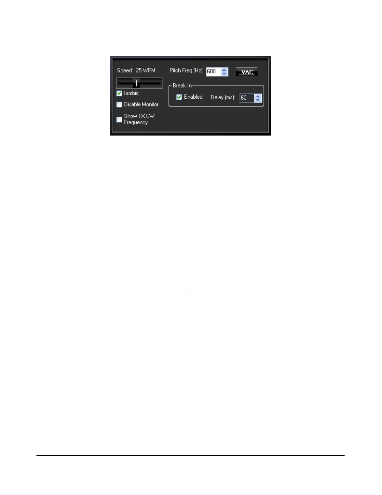
F R O N T C O N S O L E C H A P T E R 5
Figure 55: Mode Specific Controls - CW
Speed: sets the CW speed when using the internal keyer in Iambic mode. Adjust the speed
with the slider.
Iambic: check to set the internal keyer to Iambic mode (see also page 133)
Disable Monitor: check to disable the monitor (this can be useful when using an external
keyer).
Show TX CW Frequency: check to show the CW transmit frequency as a single yellow line
when the display is set to Panadapter. It can be an especially useful visual aid when operating
split to position your transmit frequency where desired (in a pile-up) using VFO B.
Pitch Freq (Hz): sets the desired audio frequency for CW listening at the center of the CW
filters. This will determine the offset that is applied to the carrier in receive and transmit. The
display will continue to read the actual carrier frequency, but the software will provide for an
offset to get the desired CW tone. This pitch will determine the automated tuning frequency
using the display and mouse ClickTune™ functions.
VAC: click to enable Virtual Audio Cable (http://software.muzychenko.net/eng/), a third party
program (written by Eugene Muzychenko) to enable digital audio transfer between PowerSDR
and other third party (digital) programs. See also the Setup Form – Audio Tab, VAC Sub-Tab
described on page 117. VAC is not automatically enabled for CW modes, even if Auto Enable
has been checked on the VAC Sub-Tab.
Break In: check the Enabled box to activate Break In for the internal keyer. Set the delay in
the Delay text box. See also page 134.
[The rest of this page has been left blank intentionally]
F3K-M2.0/4 69 2003-2010 FlexRadio Systems

F R O N T C O N S O L E C H A P T E R 5
Digital Controls
The digital controls, shown below are available when either DIGL, DIGU or DRM is selected. These
controls can mostly be found on the Setup Form- Audio Tab, VAC Sub-Tab (see page 117, where you
can also find a more detailed description).
Figure 56: Mode Specific Controls - Digital
VAC: click to enable Virtual Audio Cable (http://software.muzychenko.net/eng/), a third party
program (written by Eugene Muzychenko) to enable digital audio transfer between PowerSDR
and other third party (digital) programs. See also the Setup Form – Audio Tab, VAC Sub-Tab
described on page 117. If Auto Enable (page 118) has been checked on VAC Sub-Tab, then
VAC will automatically be enabled when either DIGL, DIGU or DRM is selected.
RX & TX Gain: Adjust the gain for signals coming in and out of the VAC interface. Use the RX
Gain control to adjust the audio level going to third party programs. (Note that for third party
applications this control supersedes the front panel AF control). Similarly, use the TX control to
adjust the volume of audio coming from third party applications (adjust for 0 dB on the ALC
meter).
Sample Rate: sets the sample rate of the VAC interface. This needs to be matched to your
third party software sample rate.
Mono/Stereo: sets the VAC interface to operate either mono or stereo. This can be of
importance, depending on your third party software. (E.g. MixW requires the mono setting,
whereas DREAM requires stereo).
(9) Display Controls
The main display controls, shown in Figure 57 below, consist of two sections: Screen adjustment
controls and display selection controls. The former act on the screen as a whole, whereas the latter
determine the display type to be used.
[The rest of this page has been left blank intentionally]
F3K-M2.0/4 70 2003-2010 FlexRadio Systems

F R O N T C O N S O L E C H A P T E R 5
Figure 57: Display Controls
Screen Controls
The screen controls adjust the view of the Panadapter, Waterfall or Panafall display (see Figure 59 and
Figure 60 below), they are not functional for any of the other display types.
Pan: adjust the slider to pan the Panadapter or Waterfall display from left to right. Click on
Center to quickly center the display.
Zoom: adjust the slider to zoom in on or out of the display. Additionally click on either on of the
4 buttons to the right to quickly zoom to the labeled setting. (The maximum frequency span of
the Panadapter or Waterfall is dependent on the audio sample rate setting)
Display Selection Controls
The main display is able to visualize received (and transmitted) signals in various ways (display types),
which can be selected from the list box. These various display types are detailed below with a snapshot
of each type. The refresh rate (in Frames Per Second, FPS) of the main display can be modified on the
Setup Form-Display Tab (see page 121).
AVG (Average): click to view time-averaged signals. This will smooth fast-changing signals
and is a good way to separate real from stochastic (noise) signals. The averaging time can be
set on the Setup Form-Display Tab (see page 120). AVG must be enabled for the 0 Beat VFO
Control to be available.
Peak: click to hold the peak value for each frequency in the display.
Display Type Descriptions
Note: The actual display in PowerSDR is crisper than the compressed images
shown below.
There are six frequency domain display types (Spectrum, Panadapter, Histogram Waterfall, Panafall™
and Panascope™) and three time domain display types (Scope, Phase and Phase2). Various colors
used in the display (text, data line, etc) are customizable using the Setup Form-Appearance Tab,
Display Sub-Tab (page 144).
F3K-M2.0/4 71 2003-2010 FlexRadio Systems

F R O N T C O N S O L E C H A P T E R 5
Spectrum
Figure 58: Spectrum Display
The Spectrum Display shows a classical spectral view of the frequency with the ends of the display
determined by the bandwidth of the filter. The scale across the top shows the frequency offset in Hz
from the VFO A frequency. Rather than only using half the display window when in lower or upper
sideband, we expand the display moving the 0 Hz line to the left or right margin (1.2 kHz tone in USB
mode with a 2.7 kHz filter shown).
Panadapter (Panoramic Adapter)
Figure 59 Panadapter Display
The Panadapter Display is similar to the Spectrum Display with several differences.
The maximum display width is a function of the selected sampling rate, no matter what filter
bandwidth is selected.
The selected filter is displayed as an overlay to help the user visualize the filter. Shown are the
main RX filter (gray, VFO-A), the MultiRX filter (blue, VFO-B) and the TX filter edges (yellow
vertical lines). The color of all the filter overlays can be changed independently using the Setup
Form-Appearance Tab, Display Sub-Tab (page 144).
F3K-M2.0/4 72 2003-2010 FlexRadio Systems

F R O N T C O N S O L E C H A P T E R 5
The frequency scale shows the actual frequency (in MHz).
The edges of the amateur bands are marked as red vertical lines and the corresponding
frequencies are displayed in red
With the mouse, filters and filter edges can be varied by dragging and dropping
Point click tuning is available with mouse and cross-hairs showing.
The Panadapter is useful because although you hear only the signals within the audio passband, you
can see in real time all signals within the receiver’s passband (as determined by the sampling rate).
This gives a much more complete picture of the surrounding area in the band, especially when there is
abundant signal activity (e.g. contest and DX situations).
Waterfall
Figure 60: Waterfall Display
The Waterfall Display shows a scrolling view of activity within the receiver's passband (as determined
by the sampling rate). This makes tracking narrow band signals much easier and can even allow
visualization of CW signals at slower speeds (longer line is a dash, short line is a dot, no line is a
pause).
Across the top the audio passband filters are displayed, similar to the panadapter.
The filter widths and positions can be adjusted with the mouse, similar to the panadapter.
All mouse tuning methods available in the panadapter are also available in the waterfall.
The frequencies corresponding to the Amateur band edges are displayed in red.
The Waterfall Display can be customized on the Setup Form- Display Tab This allows custom setting of
the dynamic range and coloring for the display. (See the Setup Form-Display Tab on page 122 for
more details.)
F3K-M2.0/4 73 2003-2010 FlexRadio Systems

F R O N T C O N S O L E C H A P T E R 5
Histogram
Figure 61: Histogram Display Mode
The Histogram Display is similar to the Spectrum Display, but instead of a single color data line,
additional colored data is used. Blue signals are real-time (current) signals that are below a signal
threshold (roughly below the average plus a small margin). The red signals are real-time (current)
signals that are above that same threshold. The green signals are previous peaks on that same
frequency that will fade as time goes by (a type of history, hence the name).
Scope
Figure 62: Scope Display
The Scope Display shows the received or transmitted audio signal in the time domain. Shown is an SSB
signal. The Scope Display is particularly useful when transmitting to monitor your audio waveform, e.g.
to see the effects of DX (page 67) or equalization (page 91). The time base can be adjusted on the
Setup Form- Display Tab (see page 123).
[The rest of this page has been left blank intentionally]
F3K-M2.0/4 74 2003-2010 FlexRadio Systems

F R O N T C O N S O L E C H A P T E R 5
Phase
Figure 63: Phase Display
The Phase Display maps the filtered I and Q (Left and Right) channels to the X and Y coordinate
planes. This is useful for making sure the two channels are 90 degrees out of phase as they should be.
There is also a Phase2 Display that maps the unfiltered data directly from the ADC. When a
continuous carrier signal is received, the unfiltered data in the Phase2 Display should produce as near
to a perfect circle as possible. If the circle distorts into an oval or a straight line, the input phase is off
balance which would indicate a connection or hardware problem.
Panafall
This display is a combination of the Panadapter and the Waterfall displays described above.
Panascope
This display is a combination of the Panadapter and the Scope displays described above.
Off
In this setting the display is turned off. It is mainly used for debugging purposes, but can also be used
with slower systems to decrease the CPU load to more reasonable levels.
Cursor and Peak Position
There are two sets of data side by side just below the graphical display that are used to communicate
cursor (left) and peak signal (right) information to the user. For each the data shown equals Offset from
VFO, Signal Level and Frequency. For example, in Figure 64 below, the peak signal is offset –
28742.6 Hz from the VFO frequency ( 14.255 MHz). The peak signal level is –92.5 dBm, and the peak
signal is at 14.226257 MHz. Note that these values are fairly low resolution due to the discrete nature
of the pixel display.
[The rest of this page has been left blank intentionally]
F3K-M2.0/4 75 2003-2010 FlexRadio Systems

F R O N T C O N S O L E C H A P T E R 5
Figure 64: Cursor and Peak Position Information
In the frequency domain displays (Spectrum, Panadapter, Histogram, Waterfall), right clicking
the mouse cycles through yellow crosshairs, red crosshairs (only if SPLT or MultiRX is
enabled), or no crosshairs. The crosshairs span the width and height of the display (yellow
cross hairs are shown in Figure 64 above).
Together with the AVG control they allow easy measurement of signals on the display. For
example, in Figure 64 the cursor position is offset -10219.9 Hz from the VFO frequency and is
at 14.244780 MHz. The horizontal line of the crosshairs is at -96.0 dBm.
Another feature of the crosshairs is ClickTuning. Clicking the left mouse button with the yellow
crosshairs visible tunes VFO A to the frequency indicated by the cursor position data (or if Snap
ClickTune is on (see page 110), to the nearest multiple of the Tune Step). The red crosshairs
tune VFO B when SPLT or MultiRX is enabled. This is an excellent way to tune CW signals as
it will zero beat the tone to the set CW pitch.
(10) MultiRX Controls
The MultiRX controls, shown below, allow you to enable a second receive channel within the receiver's
passband as determined by the audio sample rate setting. Both the primary and the secondary receive
channel can be positioned independently in the audio spectrum to facilitate separating the two signals
in your head.
Figure 65: MultiRX Controls
Click MultiRX to enable the second receive channel. The second receive channel will be tuned to the
frequency shown in VFO B. In the Panadapter and Waterfall Displays, its passband is shown in blue, but
only if it is within the range of the Panadapter/Waterfall. Use the upper and lower horizontal sliders to
position the primary and secondary channel respectively anywhere in the left-right audio spectrum. Use
the left and right vertical sliders to adjust their respective volumes. Click Swap to swap the audio
between the left and right speakers.
F3K-M2.0/4 76 2003-2010 FlexRadio Systems

F R O N T C O N S O L E C H A P T E R 5
Hint: In split operation you can use the secondary receive channel to listen
to the pile-up, while using the primary receive channel to listen to the
DX.
(11) DSP Controls
Figure 66: DSP Controls
These controls enable the digital signal processing (DSP) functions. The first four are described in detail
in the Setup Form-DSP Tab, Options Sub-Tab (see page 124); SR (Spur Reduction) is described in the
Setup Form-General Tab, Options Sub-Tab (page 109).
NR (DSP Noise Reduction): Activates the DSP Noise Reduction algorithm (see page 124).
ANF (Automatic Notch Filter): Activates the Automatic Notch Filter algorithm (see page
125).
NB (Impulse Noise Blanker): Activates the Noise Blanker algorithm (see page 127).
NB2 (Mean Rank Noise Blanker): Activates the Mean Rank Noise Blanker algorithm (see
page 127).
SR (Spur Reduction): Activates the Spur Reduction algorithm (see page 109).
BIN (Binaural Audio): Activates the Binaural algorithm. Binaural audio is a special feature of
PowerSDR. It generates a pleasing effect as the two phased channels (I and Q) are mapped to
the left and right audio channels. The phasing of the demodulated and filtered audio signal
within the passband gives a stereo-like, spatial effect to the received signal. When tuning across
CW signals, they will seem to move in “space” as you tune the radio. Many experienced
operators feel that binaural audio gives them a competitive advantage under contest conditions
where the effect allows them to more easily pick signals out of a pile up. Wearing headphones
increases the effect of the spatial separation.
Note: BIN is not available when operating FMN, AM or SAM.
[The rest of this page has been left blank intentionally]
F3K-M2.0/4 77 2003-2010 FlexRadio Systems

F R O N T C O N S O L E C H A P T E R 5
(12) VFO Controls
Figure 67: VFO Controls
SPLT (Split): Enables Split operation using VFO B for the transmit frequency. The frequency
text and TX indicator in VFO B will turn red to indicate that it is the transmit frequency.
0 Beat: Centers the signal peak within the RX filter passband. An exception is made in CW
mode if the CW Pitch is within the passband. In this case, the signal is tuned to the CW Pitch.
Note: 0 Beat is only available if AVG is enabled for the Display.
IF→V: Translates any offset created by Filter Shift and shifts it back to baseband. Useful when
chasing a signal with the Filter Shift control (see also page 66).
A >B: Transfers the contents of VFO A to VFO B (frequency, mode, and filter).
A< B: Transfers the contents of VFO B to VFO A (frequency, mode, and filter).
A< >B: Swaps the contents of VFO A and B (frequency, mode, and filter).
XIT (Transmit Incremental Tuning): Click to enable XIT. XIT may be used as a quick way to
operate split at a specific offset. When enabled, the transmit frequency is increased from the
VFO A frequency by the amount shown in Hz while leaving the receive frequency intact. With
SPLT activated, XIT modifies the VFO B frequency. Click the 0 button next to the XIT button to
clear the XIT control to 0.
RIT (Receive Incremental Tuning): Click to enable RIT. When enabled, the receive
frequency is increased from the VFO A frequency by the amount shown in Hz while leaving the
transmit frequency intact. Click the 0 button next to the RIT button to clear the RIT control to
0.
(13) CPU %
This displays your computer's total CPU load as seen in the Windows Task Manager under the
Performance Tab. Note that running other applications will cause the CPU load to increase. If your CPU
load is peaking at close to 100%, audio and possibly video artifacts will become noticeable. In this case
closing ancillary applications (e.g. email, web browser, etc.) and/or deactivating some of PowerSDR's
functions (e.g. NR, ANF, BIN, etc.) may improve the performance.
F3K-M2.0/4 78 2003-2010 FlexRadio Systems

F R O N T C O N S O L E C H A P T E R 5
(14) Start/Stop Button
Click Start to activate PowerSDR, click Stop to deactivate it (see Figure 68).
PowerSDR
Off
PowerSDR
On
Figure 68: Power Button States
Note: Please see also the Power-Up/Down procedures described on page 40
for information on best practices.
(15) MON (Monitor)
When enabled, the transmitted audio is monitored through the receiver’s speakers. The MON function
is not available in AM, SAM, or FM modes as those modes are transmitted at the Intermediate
Frequency (IF, usually 9 kHz). In voice operation the MON feature will allow you to hear the effects of
MIC gain, TX equalization, compression and compansion and to adjust them in real time. The AF
control can be used to adjust the monitor volume.
(16) MOX (Manually Operated Transmit)
When enabled MOX activates the transmitter. It is used primarily for voice operation. MOX will not
generate a CW carrier. To generate a carrier for tuning, refer to the tune (TUN) button description on
page 80.
Note 1: If the radio ever seems like it is stuck transmitting, try disabling the
Push-To-Talk (PTT) function by selecting Disable PTT on the Setup
Form-General Tab, Options Sub-Tab.
Note 2: To use PowerSDR without any hardware attached to the PC you must
disable PTT. On the Setup Form-General Tab, select either Disable
PTT on the Options Sub-Tab, or Demo/None on the Hardware
Config Sub-Tab
(17) MUT (Mute)
This button Mutes the speaker audio.
F3K-M2.0/4 79 2003-2010 FlexRadio Systems

F R O N T C O N S O L E C H A P T E R 5
(18) Record () and Play ()
The Record and Play buttons offer a quick and easy way to record and play back a signal. Click
Record to record a signal and click Record again to stop recording. Once recorded, the signal can be
played back by clicking Play. Subsequently clicking Record will overwrite any audio file previously
recorded in this way. The Record and Play buttons are the same as the QuickRec and QuickPlay
buttons on the Wave Form (see page 89)
Note 1: The audio file is saved as SDRQuickAudio.wav in the
%appdata%\FlexRadio Systems\PowerSDR v2.n.n\ directory. The
saved file contains post-processed audio, and can be played back with
any wav file player.
Note 2: The location of your Application Data (%appdata%) directory depends
on your version of Windows. To open your Application Data directory,
click Start on the Windows task bar and then click Run. Type
%appdata% and click OK.
(19) TUN (Tune)
TUN transmits a continuous (CW) carrier at the level set with the Tune Power control (default 10W)
on the Setup Form-Transmit Tab (page 137) and outputs a tone at the CW Pitch. This power is shown
on the Drive control while TUN is activated. Any changes to the Drive control while TUN is active are
saved when the TUN button is turned off.
(20) ATU and BYP
The ATU and BYP buttons are clicked to respectively activate and bypass the internal ATU. They also
indicate the various states of the ATU as shown in Figure 69 below.
ATU/BYP Situation
BYP clicked
ATU clicked, but SWR already OK
Band changed
ATU clicked and match is found
ATU clicked and match not found
Figure 69: States of the ATU and BYP buttons
Initially when you start PowerSDR or whenever you change the band the internal automatic antenna
tuner will be bypassed, as indicated by the BYP button being active (yellow) and ATU button being
inactive.
F3K-M2.0/4 80 2003-2010 FlexRadio Systems

F R O N T C O N S O L E C H A P T E R 5
Press ATU to initiate a tuning cycle. The ATU first measures the SWR.
If SWR is OK, then no further action is taken and the ATU remains bypassed.
If SWR is not OK, a tuning cycle is started
o If a match is found, the ATU button turns green.
o If a match cannot be found, the ATU button turns red and BYP yellow
Note: When operating Split, any change of the receive and/or transmit
band (e.g. cross-band operation) will bypass the ATU.
(21) AF (Audio Frequency Gain)
This control sets the audio gain. It may also be adjusted by pressing the + (plus) and – (minus) keys
on the numeric keypad. For best performance set the external speaker volume control to the high end
of the scale so that the AF control can be set to a lower value.
(22) AGC-T (AGC Maximum Gain)
This control sets the maximum gain of the AGC. It is the same control as can be found on the Setup
Form-DSP Tab, AGC/ALC Sub-Tab (page 135). The operational use of the AGC control is essentially the
same as that of an RF gain control found in more traditional receivers. There are several articles on
configuring and optimizing the AGC in our Knowledge Center which may also be of use. (Search for
AGC in our Knowledge Center at http://kc.flex - radio.com/search.aspx ).
Hint: For optimal use, set the AGC-T control such that the band noise level
is comfortable, yet weak signals still jump out of the noise. Then
adjust the AF control to comfortably hear the received signal.
(23) Drive (Transmitter Power Output/Tune Power)
This control adjusts the percentage of maximum power that will be available when transmitting. The
Drive control may be adjusted while either receiving or transmitting.
Note: The control doubles in function as the power level setting for the TUN
(Tune) button described above. The Tune power may be adjusted
while the TUN button is activated or by using the control on the
Setup Form-Transmit Tab.
F3K-M2.0/4 81 2003-2010 FlexRadio Systems

F R O N T C O N S O L E C H A P T E R 5
While great care is taken to ensure that this value is accurate and that selecting a Drive value will give
approximately that amount when using the 100W PA, there are variances in the filter components and
transmitter characteristics that make it difficult for this to be exactly right over the whole range (1-
100).
(24) AGC (Automatic Gain Control)
This control sets the Automatic Gain to one of the following settings: Fixd (Fixed or off), Long, Slow,
Med (Medium), Fast, or Custom. The Custom setting uses the controls on the Setup Form-DSP Tab,
AGC/ALC Sub-Tab (page 135), where also a more expansive explanation of the AGC can be found.
(25) RX Gain
The RX Gain is in actual fact a 26 dB preamp combined with a 20 dB attenuator. This control enables
selection of the preamp/attnenuator states: ATTN, Off, and Pre. The corresponding preamp and
attenuator settings are shown in Table 9.
Table 9: RX Gain Details
ATT
Setting
Attn On Off -20
Off Off Off 6
Pre Off On 26
(20 dB)
Gain
(26 dB)
Net Gain
(dB)
(26) SQL (Squelch)
Figure 70: Squelch Controls
The SQL button enables the Squelch function. The threshold can be set with the slider and its value (in
dBm) is displayed numerically. The bar graph displays in green the signal level below the threshold
(squelch closed) and in red above (squelch open: only the red level is audible with SQL enabled).
Squelch can be very useful to remove all noise from CW signals, especially in narrow filter settings.
(27) Date/Time Display
Figure 71: Date/Time Display
The date and time display can be especially helpful when taking screenshots, but can also be a quick
reference to UTC time for those of us who are “time zone challenged.” Click inside the Date or Time
area to cycle between LOC (Local Time), UTC (UTC Time), and Off .
F3K-M2.0/4 82 2003-2010 FlexRadio Systems

F R O N T C O N S O L E C H A P T E R 5
(28) Setup Form
The Setup Form contains numerous controls for everything from the hardware configuration to transmit
settings. Please refer to the Setup Form chapter on page 103 for more detailed information.
(29) – (34) Operating Forms
Each of these items opens a form, which is used while operating. Please refer to the Operating Forms
chapter below for more detailed information on each one.
[The rest of this page has been left blank intentionally]
F3K-M2.0/4 83 2003-2010 FlexRadio Systems

Chapter
6
Operating Forms
This chapter describes each of the so-called operating forms. You can access each form individually by
clicking on the relevant menu item to the right of Setup at the top left of the front console (see Figure
72). For ease of reference, the numerical identifiers from the previous chapter on the Front Console are
repeated in this chapter. Additionally, the key combination Ctrl-Shift-I activates the voltage and
temperature form (see page 101)
Figure 72: Operating Form Identifiers
[The rest of this page has been left blank intentionally]
F3K-M2.0/4 85 2003-2010 FlexRadio Systems

O P E R A T I N G F O R M S C H A P T E R 6
(29) Memory Form
Click the Memory menu to save and recall information such as frequency, mode, filter and various
other settings.
Save…
Opens the Save Memory Channel form as shown in the figure below.
Figure 73: Save Memory Channel Form
The current Mode, Filter, Step Size, Frequency, Squelch and AGC settings are
automatically transferred from the console. The Group Drop Down Box allows a further level of
characterization of the type of entry. In the future this Group list will be customizable. The
Callsign and Comments fields are free form and the user can enter details as desired. Clicking
the OK button will save the information shown above into the memory database before closing
the form. Clicking Cancel simply closes the form (the data is not saved).
[The rest of this page has been left blank intentionally]
F3K-M2.0/4 86 2003-2010 FlexRadio Systems

O P E R A T I N G F O R M S C H A P T E R 6
Recall…
Presents the user with a Memory form with data from all previously stored memory locations (shown in
the figure below).
Figure 74: Memory Form
The data grid displays each memory that has been saved to the database. Clicking in the left
hand margin will allow a particular memory to be selected. Clicking on the column titles will sort
the data using the information in that column. Repeatedly clicking will alternate between
ascending and descending order as indicated by the small arrowhead in the column title.
Edit: Clicking Edit causes all fields in all records to become editable. Thus to change
Group, e.g., in two different entries you would click Edit, then click on the Group field of
the first entry to be changed, alter the contents and then click on the Group field of the
second entry and alter it. When done, click the Edit button again to stop the editing
process. When you click the Close button your work will be saved.
Recall: Click the Recall button to send the data in the memory to the Front Console
(i.e., restore a memory). You can also double-click on a row to accomplish this, although
this method is less consistent. Select Close on Recall to close the Memory Form when
clicking Recall.
F3K-M2.0/4 87 2003-2010 FlexRadio Systems

O P E R A T I N G F O R M S C H A P T E R 6
Delete: Click the Delete button to remove a memory from the database. A prompt will
be shown to prevent unintended loss of memories.
(30) Wave Form
Figure 75: Wave Form
The Wave form allows the user to Record and Playback either the post-processed audio (see page 90)
of the current station, or up to 96 kHz bandwidth (as determined by the audio sample rate setting) of
pre-processed IF (I and Q) “audio” (see page 90) from the FLEX-3000.
Note: The recorded audio is always played back through PowerSDR. So if
you record 96 kHz of pre-processed bandwidth and play it back with
PowerSDR set to Receive you will see all the signals within that
bandwidth and be able to tune them, filter them etc, as if you were
actually receiving those signals. If on the other hand you record postprocessed audio and play it back with PowerSDR set to Transmit you
will be transmitting the audio you received and recorded.
[The rest of this page has been left blank intentionally]
F3K-M2.0/4 88 2003-2010 FlexRadio Systems

O P E R A T I N G F O R M S C H A P T E R 6
Playback
Currently Playing: Displays the filename of the currently playing wave file.
Play: Click this button to start or stop playback of the current wave file. Note that clicking this
button twice while a file is playing will restart the file.
Pause: Pauses the wave file playback. Click once to pause and again to resume playback.
Prev (Previous): When there is more then one file in the playlist, clicking this button will
cause the previous file in the list to begin playing.
Next: When there is more than one file in the playlist, clicking this button will cause the next
file in the list to begin playing.
Playlist
Add…: Click this button to open a file menu to select wave file(s) to add to the playlist. Note
that incompatible wave files will be removed from the list when they are played for the first
time.
Remove: Removes the currently selected file in the playlist. If the file is currently being played,
then you will be prompted asking if you would like to stop playing the file and remove it from
the list.
Loop: When there is more than one file in the playlist, enabling this option allows playback to
continue after finishing the last wave file in the list. At this point it will start playing the file at
the top of the list.
Record
Click the Record button to begin recording a wave file. Click it again to complete the recording. The
wave file will be date and time stamped automatically and saved in the the %APPDATA% folder, the
exact location of which depends on your operating system (Windows XP, Vista or 7, see the notes
under Record () and Play () on page 80).
TX Gain (dB)
Use this control to adjust the volume of audio being played back when transmitting. Use this control
instead of the MIC control on the front console to calibrate transmit (adjust for 0 dB on the ALC
meter).
Quick Rec and Quick Play
The Quick Rec and Quick Play buttons offer a quick and easy way to record and play back a signal
audible on the receiver. Click Quick Rec to record a signal and click Quick Rec again to stop
recording. Once recorded, the signal can be played back by clicking Quick Play. Subsequently clicking
Quick Rec will overwrite any audio file previously recorded in this way. These two buttons perform the
same function as the Record () and Play () buttons on the Front Console (see page 80).
F3K-M2.0/4 89 2003-2010 FlexRadio Systems

O P E R A T I N G F O R M S C H A P T E R 6
Record Options
Click Options at the top of the Wave Form (see Figure 75) to open the following form:
Figure 76: Wave Recording Options
The Wave Record Options can be used to modify what is recorded in either receive or transmit modes.
Receive
Pre-Processed Audio will record the whole bandwidth of the receiver input. The bandwidth is
determined by the sample rate you set on the Setup Form-Audio Tab, Primary Sub-Tab. This is
useful for playing back through PowerSDR at a later time (e.g. for demonstration purposes).
Post-Processed Audio will record only the filtered, AGC’d audio as you hear it coming out of
the speaker. This is useful for playing back the received audio through a typical wav file player
(not a part of PowerSDR).
Transmit
Pre-Processed Audio will capture the audio as it is seen at the microphone input without any
of the effects of filtering, compression, companding, equalization or any other audio processing
features that may be turned on in the transmit chain.
Post-Processed Audio allows the recording to capture the audio after it has been filtered,
compressed, companded, equalized or modified by any other audio processing feature turned
on in the transmit chain.
Sample Rate
Sets the sample rate at which the wave file will be recorded.
[The rest of this page has been left blank intentionally]
F3K-M2.0/4 90 2003-2010 FlexRadio Systems

O P E R A T I N G F O R M S C H A P T E R 6
(31) Equalizer Form
There are two equalizers available: a 3-band and a 10-band equalizer. These equalizers tailor the shape
of the passband of an audio channel, much the same as the treble and bass controls do on an ordinary
radio. The equalizers may be enabled either from the Equalizer Form or in the phone modes, from the
Front Console (see page 67)
3-Band Equalizer
Figure 77: Three-Band Equalizer Form
In most situations the 3-Band Equalizer will suffice. The receive and/or transmit audio can be modified
by adjusting the gain for the Low, Mid and High audio bands. The Preamp applies gain across the
whole audio spectrum. Easily compare the audio with and without the equalizer using the Enabled
check box. The Reset button will reset all of the sliders to the 0 dB position.
F3K-M2.0/4 91 2003-2010 FlexRadio Systems

O P E R A T I N G F O R M S C H A P T E R 6
Hint: Hover with your mouse over a slider to see its frequency range of
operation.
10-Band Equalizer
Figure 78: Ten-Band Equalizer Form
The 10-Band Equalizer offers a finer degree of audio frequency control than does the 3-band equalizer.
You may want to use this equalizer if the 3-band equalizer does not give you the result you want.
[The rest of this page has been left blank intentionally]
F3K-M2.0/4 92 2003-2010 FlexRadio Systems
 Loading...