

Page 1
INSTRUCTIO N MA NUA L
MODEL NO.: FLEXC II-12PX
FLEXC II-9PX
FLEXC II-6PX
FLEXC II-3PX
18V Brushless Cordless Torque Screwdrivers
Rev 1. 5/18/2012
www.mountztorque.com
Page 2
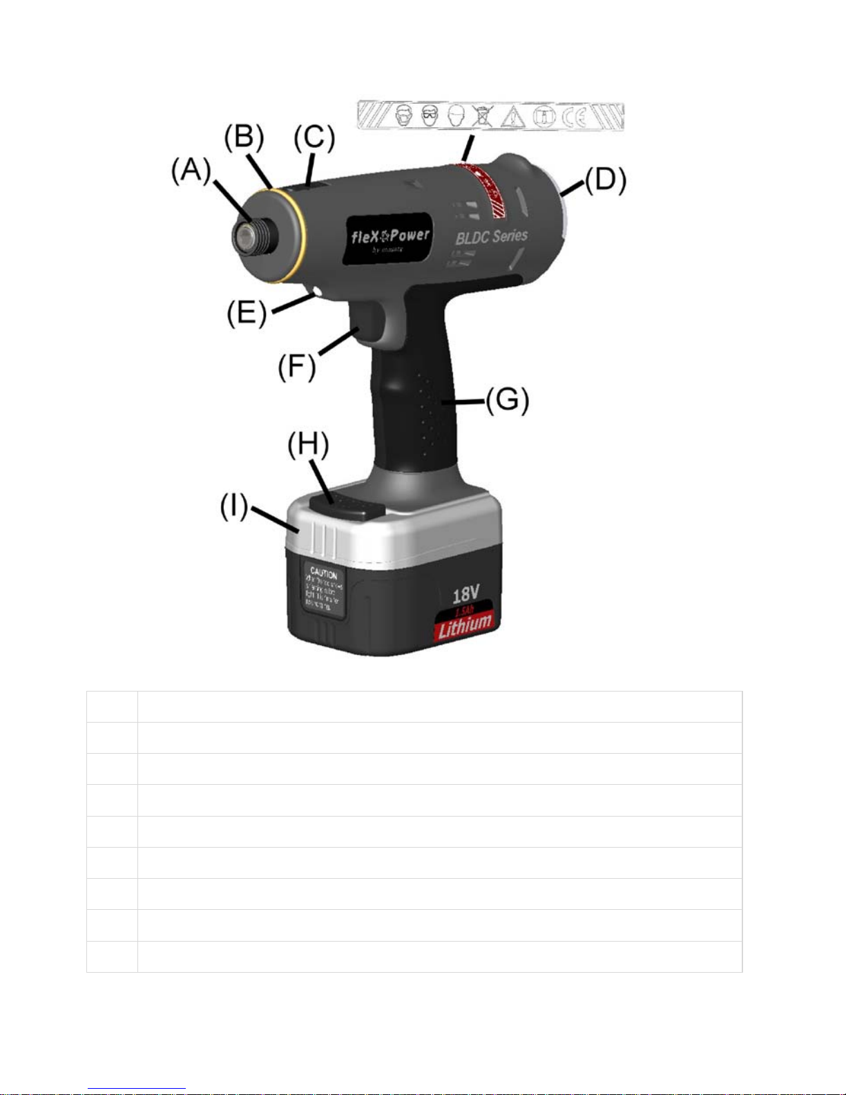
FUNCTIONAL GUIDES
(A) 1/4" F/Hex with quick change chuck
(B) Color Ring - color code specific torque values in production areas.
(C) Torque adjustment cover
(D) LED indicator provides simple process information to the operator
(E) LED light for working in dark area
(F) Trigger repeat protection. Avoid double hits on already seated screw
(G) Soft texture ergonomic grip.
(H) Quick release button. Easily slide and change battery.
( I ) High capacity Li-ion battery pack delivers longer run-time
- 2 -
Page 3

WARNING! "READ ALL INSTRUCTIONS" Always observe the safety
regulations appl icable in your country to reduc e the risk of fire, electric shock and
personal injur y. Understand th e following saf ety instructions bef ore attempting to
operate this pr oduct. Always wear e ye protectio n when working w ith power t ools.
Keep these instructions in a safe place.
SAVE THESE INSTRUCTIONS
Work Area Safety
General Safety Rules
Personal Safety
- 3 -
Keep your work area clean and
well lit. Cluttered benc h es and
dark areas invite accidents.
Do not operate power tools in
explosive atmospheres, such as
in the presence of flammable
liquids, gases, or dust. Power
tools create sparks which may
ignite the dust or fumes.
Keep bystanders, children, and
visitors away while operating a
power tool. Distractions can
cause you to lose control.
Stay alert, watch what you are
doing and use common sense
when operating a power tool. Do
not use tool while tired or under
the influence of drugs, alcohol,
or medication. A moment of
inattention while operati ng po wer
tools may result in serious personal
injury.
Dress properly. Do not wear
loose clothing or jewelry.
Contain long hair. Keep your
hair, clothing, and gloves away
from moving parts. Loose
clothes, jewelry, or long hair can be
caught in moving parts.
Do not overreach. Keep proper
footing and balance at all times.
Proper footing and balance
enables better control on the tool in
unexpected situations.
Use safety equipment. Always
wear eye protection. Dust mask,
non-skid safet y shoes, hard hat , or
hearing protection must be used
for appropriate conditions.
Tool Use and Care
Use clamps or other practical
ways to secure and support the
work piece to a stable platform.
Holding the work piece by hand or
against your body is unstable and
may lead to loss of control.
Do not force tools. Use the
correct tool for your application.
The correct tool will do the job
better and safer at the rate for
which it is designed.
Do not use tool if switch does
not turn it on or off. Any tool that
cannot be controlled with the switch
is dangerous and must be repaired.
Store idle tools o u t o f re ach o f
children and other untrained
persons. Tools are dangerous in
the hands of untrained users.
Check for misalignment or
binding of moving parts,
breakage of parts, and any other
condition that may affect the tool
operation. If damaged, have the
tool serviced before using. Many
accidents are caused by poorly
maintained tools.
Page 4

- 4 -
Use only accessories that are
recommended by the manufacture
for your model. Accessories that
may be suitable for one tool, may
become hazardous when used on
another tool.
Service
Tool service must be performed
only by qualified repai r
personnel. Service or maintenance
performed by unqualified personnel
could result in a risk of injury.
When servicing a tool, u se o n ly
identical replacement parts.
Follow instructions in the
Maintenance section of this
manual. Use of unauthorized parts
or failure to follow maintenance
instructions may create a risk of
electric shock or injury.
Additional Safety Rules
for Shut Off Screwdriver
Battery Charger
Caution: To reduce risk of injury,
charge only the authorized
batteries. Other types of battery
may burst, causing personal injury
and damage.
Before using battery charger, read
all instructions and cautionary
markings on batteries, chargers and
products using batteries.
Do not allow anything to cover or
clog the charger vents.
Do not expose charger to rain,
snow or wet conditions.
To reduce the risk of damage to
electric plug and cord, pull by plug
rather than cord when
disconnecting charger.
Use of an attachment not
recommended or sold by the
manufacturer may result in a risk of
fire, electric shock, or injury to
persons.
Make sure cord for charger is located
so that it will not be stepped on,
tripped on, tripped over, or otherwise
subjected to damage or stress.
Do not abuse the power cord. Never
use the cord to carry the charger.
Keep cord away from heat, oil, water,
sharp edges, or moving parts.
Replace damaged cords
immediately.
Do not operate charger if it has been
damaged in any way, take it to a
qualified service center for repair.
To reduce risk of electric shock,
unplug charger from outlet before
attempting any maintenance or
cleaning. Turning off contr ols will not
reduce this risk.
Do not disassemble charger or
battery cartridge, take it to a qualified
service center when repair is
required. Incorrect reassembly may
result in a risk of electric shock or
fire.
Battery Pack
Do not charge battery pack when
temperature is below 0
o
C (32oF) or
above 40
o
C (104oF).
Do not attempt to use a step-down
transformer, an engine generator or
DC power receptacle.
Do not short the battery pack: Do not
touch the terminals with any
conductive mater ial. Avoi d stor ing
battery cartridge in a container with
other metal objects such as nails,
coins, paper clips, etc.
Do not expose battery cartridge to
water or rain. A battery short can
cause large current flow, overheating,
possibly burns and even a break-
down.
Page 5
- 5 -
Do not store the machine and
battery pack in locations where the
temperature may reach or exceed
50
o
C (122oF).
Do not incinerate the battery pack
even if it is severely damaged or
completely worn out. The battery
pack can explode in a fire.
Be careful not to drop, shake, or
strike the battery.
Do not charge inside a box or
container of any kind. The battery
must be placed in a well ventilated
are during charging.
Do not dispose of battery packs into
household waste, fire or water.
Battery packs should be collected,
recycled or disposed of in an
environmentally-friendly manner.
Call the authorized warranty centers
for places to dispose of damaged or
inoperable batteries.
FUNCTIONAL DESCRIPTION
This industrial shut off screwdriver is
designed for nut tightening/loosening
and screw driving/loosening. It is not
appropriate to use for wood/mild steel
drilling. Please refer to the figure on the
page to familiarize yourself with the
major components of this tool before
use.
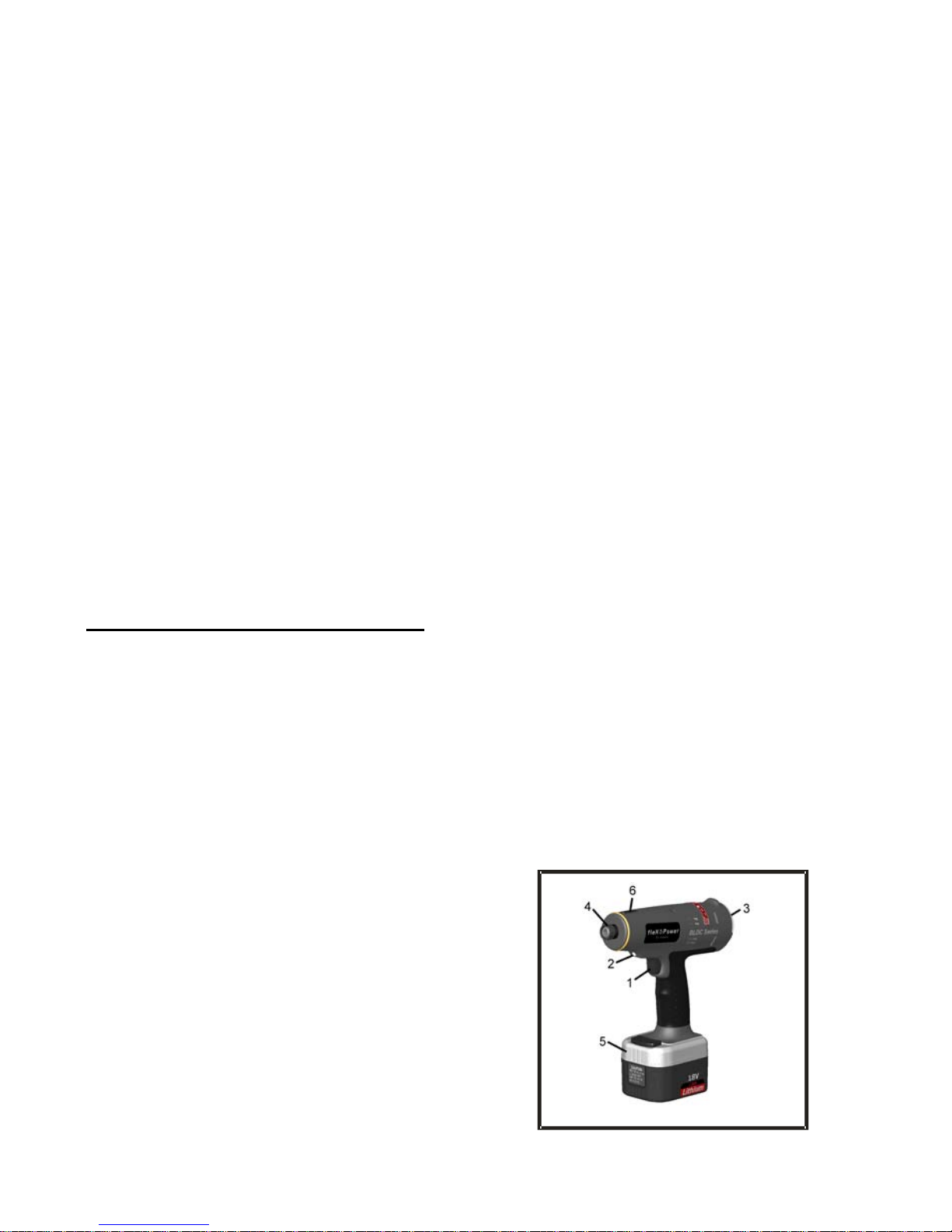
1. Power Sw it ch
Pressing the power switch wil l energi ze
the LED light (2) in front and the tool
starts to rotate. When released, power
to the motor will cease and the tool
stops to work immediately. But the LED
light will remain for 10 seconds then off.
2. Lamps
It turns on every time that the trigger
is pressed, and helps to illuminate
the darks areas.
3. Forward/Reverse Button
The tool is always in forward
operation unless the
Forward/Reverse butt on is press ed.
When the button is pressed, the blue
LED shows and the tool will be in
reverse operation. To get the tool
back in forward operation, just
simply press the button again and
the blue LED would disappear and
the tool is back in forward operation.
4. Quick Change Holder
This driver accepts only 1/4”
(6.35mm) hexagonal bits. Be sure
the bit is fully engaged b y the chuck
before operating tool. Otherwise, the
bit may fly off and cause property
damage or personal injury.
5. Li-ion Battery
This battery provides electrical
power to the motor. Please charge
it according to the charging
instruction listed in this manual.
6. Torque Adjustment Cover
Open the torque adjustment cap.
Use the torque adjustment tool to
either tighten or loosen the spring
until the desired torque is reached.
Use a torque tester to view and
verify torque setting.
Figure
Page 6
- 6 -
ASSEMBLY
Check for damage to the tool; parts or
accessories that may have occurred
during shipping. Take the time to
thoroughly read and unders tand this
manual prior to operation.
This tool kit contains:
- 1 18V cordless Shut off
Screwdriver
- 1 torque adjust tool
- 1 suspension bail
- 4 marking color ring
- 1 instruction manual
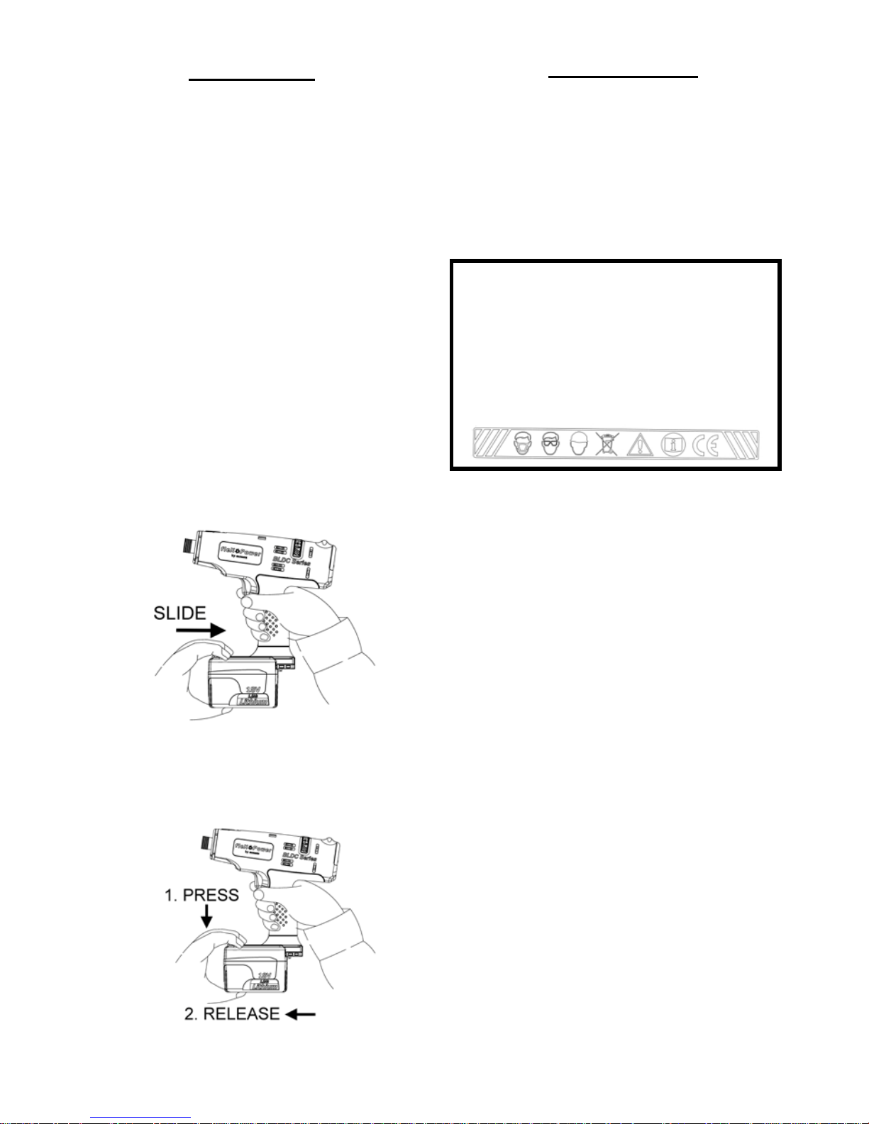
Attaching or Removing Battery Pack
1. To connect battery, line up the
tracks and attach the battery pack.
Slide toward the battery pack until it
locks into position with a click.
2. To remove the battery pack, press
the red button on the top of the
battery pack and release the battery
pack.
OPERATIONS
This product had been carefully
inspected prior to leaving the factory. It
should provide you with years of
satisfying service under normal
operating conditions. Do not, however,
force the tool to perform outside its
design parameters. Such usage will
void the warranty.
WARNING! Read the manual
instruction before operating the
tool. Always wear safety glasses or
face-shields when operating this
product. Failure to do so can result
in dust, shavings or loose particles
being thrown into your eyes.
1. Slide battery into the bottom of the
housing handle until a click sound
occurs. Do not force battery as it
should slide easily into plac e with
nominal force. Any difficulty doing so
would indicate an incorrect
alignment.
2. Select a proper size drive bit and
insert into the quick change holder.
3. Press the trigger to engage the LED
light and the tool starts to work.
Check the torque on the digital
tester to see if the desired torque
reached. If not, adjust the torque to
either tighten or loosen the spring.
See he Steps for Torque adjustment
on page 7.
4. Verify the torque requirements for the
application before the assembly
process. The torque output from the
driver can change depending on
various fastening factors like friction,
type of joint, and the type material
being used like a washer. When the
torque setting is achieved, the tool
will automatically shut off.
Page 7
- 7 -
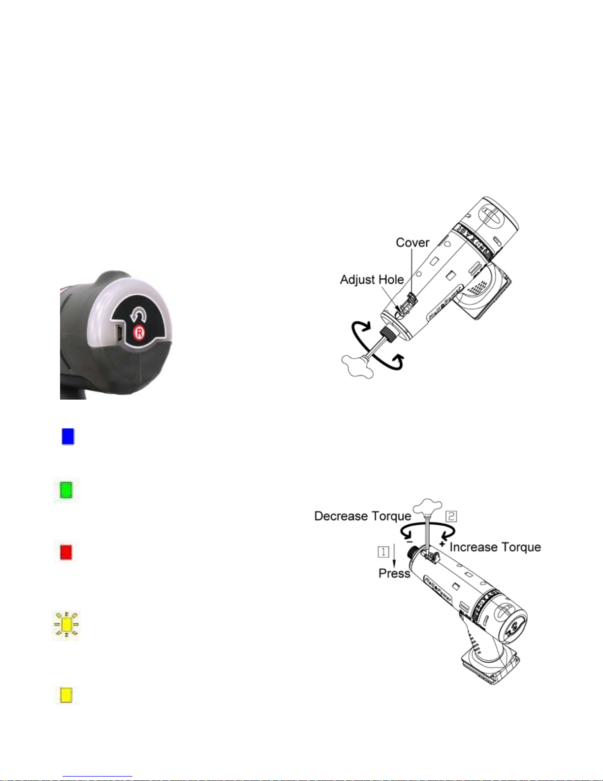
Steps for Torque Adjus tment
1. Lift the torque adjustment over. Take
the torque adjust to ol and insert it to
the quick change holder and turn
until the adjust hole shows up.
Note: To avoid danger during the
adjustment process, the battery
pack must be removed before
adjusting the torque.
2. Use the torque adjust tool to turn
clockwise to increase torque and
turn counterclockwise to decrease
torque.
Forward/ Reverse Rotation Switch
Operation
To prevent damage, do not press
Forward/Reverse button un til the an vil
comes a complete stop.
Forward Rotation Operation
Push the button for forward rotation.
After use, set the lever to its center
position.
Reverse Rotation Operation
Push the button for reverse rotation.
Check the direction of rotation before
use. After use, set the button to its
center position.
LED Indicator
When the arrow mark is blue, it
means the tool is in the reverse
operation.
A green light tells the operator that
the preset torque is reached and
the tightening is OK.
A red light and one long "beep"
sound tell the operator that the
preset torque is not reached; the
screwing fastener must be
performed again.
A flashing yellow light and five short
“beep@ sounds give an early
warning when it is time for
recharging.
A yellow light and one long “ beep"
sound means the too l is locked
and the tool cannot operate
anymore. Replace the battery pack
immediately.
Page 8
- 8 -
Charging the battery -
for Li-ion battery
[NOTE]
When charging a cool battery pack
(below 0
o
C (32oF) in a warm place,
leave the battery pack at the place
and wait for more than one hour to
warm up the battery to the level of
the ambient temperature. Otherwise
battery pack may not be fully
charged.
Cool down the charger when
charging more than two battery
packs consecutively.
Do not insert your fingers/ nails into
contact hole, when holding charger or
any other occasions.
1. Place charger in a relatively cool and
well-ventilated area.
2. Plug charger into the AC outlet.
CAUTION: Ensure that the power
source to be utilized conforms to the
power requirement specified on the
product nameplate.
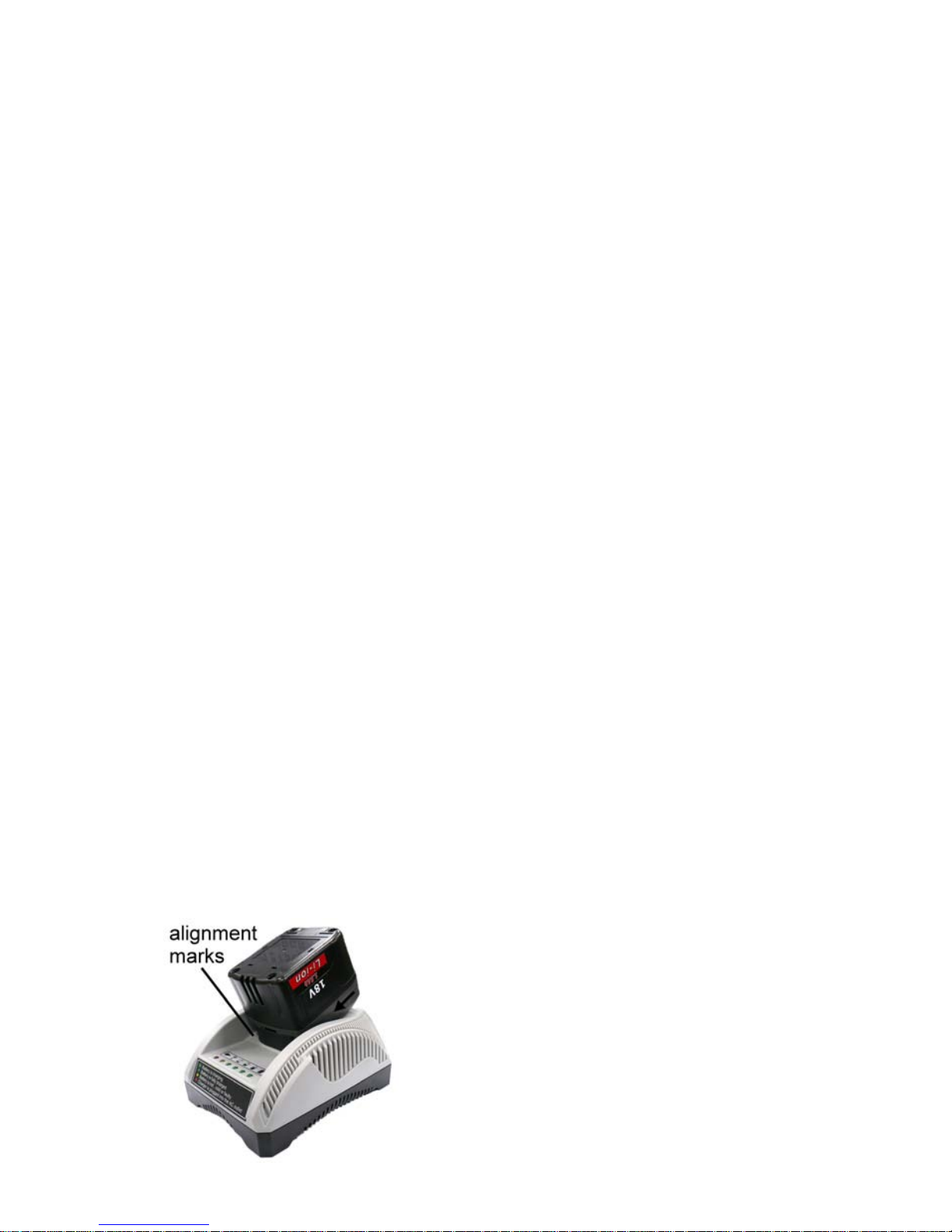
3. Turn the battery up-side-do wn and
slide the battery into charger while
keeping the alignment marks line up.
Slide the forward in the direction of
the arrow. Do not force battery as it
should slide easily into plac e with
nominal force. Any difficulty doing so
would indicate an incorrec t
alignment.
4. If the power lamp (red) does not
light immediately or goes out soon
after the charger is plugged in,
consult an authorized service
center.
5. During charging, the charging lamp
(green) will start flashing. When
charging is completed, an internal
electronic switch will automatically
be triggered to prevent
overcharging.
- Charging will not start if the battery
pack is warm. For example,
immediately after heavy-duty
operation. The yellow standby
lamp will be flashing until the
battery cools down.
6. If the temperature of the battery
pack is 0
o
C or less, charging takes
longer to fully charge the battery
pack than the standard charging
time. Even when the battery is fully
charged, it will have approximately
50% of the power of a fully charged
battery at normal operation
temperature.
7. Once the battery is fully charged,
the green lamp will be lit to indicate
the gone into a trickle charge
mode.
Li-ion Battery Pack
[NOTE]
Your battery pack is not fully charged
at the time of purchase. Be sure to
charge the battery before first use.
Page 9

M4x6L M5x6L M5x6L M6x6L
FLEXC II-3PX
Set @ 3 N.m
Set @ 1,550 RPM
3,946
FLEXC II-6PX
Set @ 6 N.m
Set @ 900 RPM
1,650
FLEXC II-9PX
Set @ 9 N.m
Set @ 700 RPM
1,943
FLEXC II-12PX
Set @ 12 N.m
Set @ 550 RPM
1,666
- 9 -
Runs Down Per Charge
Average number of fastener rundowns per battery charge. This data is for
reference only as several variables like the type of fastening joint, speed
of the tool and length of fastener can impact the charge of the battery.
Joint type : Hard joint 30˚
Battery type : Li-ion 1.5A.h
Page 10
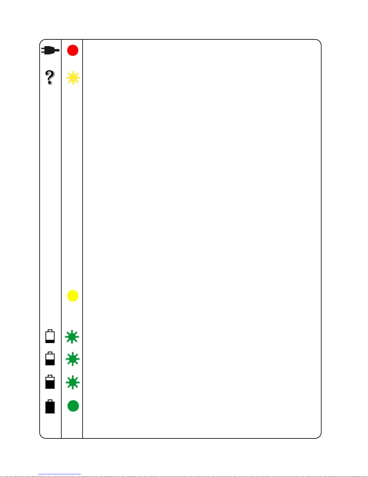
LAMP INDICATIONS
- 10 -
Red Light
Charger is plugged into the AC outlet. Ready to charge.
Yellow Flashing
(1) When the temperature of the battery is too low
(<0
o
C(<32oF)), it is in a trickle charge mode until the
temperature of the battery goes up to over 0
o
C(<32oF).
The lamp will change from the Yellow Flashing to Green
Flashing automatically and start to charge. (If after 70
minutes, the lam p changes from yellow flash ing to yellow
lit, consult an authorized service center.)
(2) When t
he temperature of the battery is too high
(>40oC(104oF)), it is in a trickle charge mode until the
temperature of the battery drops to under 40
o
C(104oF).
The lamp will change from the Yellow Flashing to Green
Flashing automatically and start to charge. (If after 70
minutes, the lam p changes from yellow flash ing to yellow
lit, consult an authorized service center.)
(3) When the voltage of the battery is too low (below 14.4
voltage), it is in a trickle charge mode until th e voltage of
the battery reaches to the standard value. The lamp will
change from the Yellow Flashing to Green Flashing
automatically an d start to charge. ( If after 20 minutes, the
lamp changes fr om yellow flashing to yellow lit, consul t an
authorized service center.)
Yellow
Light
The battery and the charger are not connected. If the yellow lit
still on after trying re-attach the battery, consul the an
authorized service center.
Green Flashing
Now start charging
Green Flashing
Battery is approximately 50% charged.
Green Flashing
Battery is approximately 80% charged.
Green Light - stop flashing
Charging is complete. (Fully charged.)
Page 11

MODEL
SPECIFICATIONS
ITEM
FLEXC II-3PX FLEXC II-6PX
Voltage 18 VDC 18 VDC
Drive Size 6.35 mm Hex. (1/4”) 6.35 mm Hex. (1/4”)
Screw Size M3 ~ M4 M3 ~ M5
Torque Range 0.8-3 N.m (7~26.6 lbf.in) 1-6 N.m (8.8 - 53.1 lbf.in)
Free Speed 500~1,550 r.p.m 300~900 r.p.m
Weight W/O Battery 0.95 kg (2.1 lb) 0.95 kg (2.1 lb)
Length 203 mm (8”) 203 mm (8”)
Battery Type Li-ion 1.5A.h Li-ion 1.5A.h
Charge Time Approx. 40 mins Approx. 40 mins
MODEL
ITEM
FLEXC II-9PX FLEXC II-12PX
Voltage 18 VDC 18 VDC
Drive Size 6.35 mm Hex. (1/4”) 6.35 mm Hex. (1/4”)
Screw Size M3 ~ M5 M4 ~ M6
Torque Range 1.5-9 N.m (13.3 - 79.6 lbf.in) 2-12 N. m (17.7 - 106.2 lbf.in)
Free Speed 300~700 r .p.m 250~550 r.p.m
Weight w/o Battery 0.95 kg (2.1 lb) 0.95 kg (2.1 lb)
Length 203 mm (8”) 203 mm (8”)
Battery Type Li-ion 1.5A.h Li-ion 1.5A.h
Charge Time Approx. 40 mins Approx. 40 mins
- 11 –
Page 12
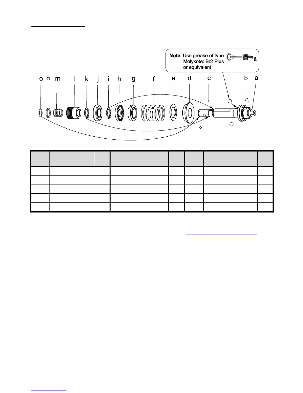
For Models:
CLUTCH UNITS
FLEXC II-3PX FLEXC II-6PX FLEXC II-9PX FLEXC II-12PX
NOTE: This chart only referenced the parts in the drawing, for ordering parts
please consult the parts list per model in our website
www.mountztorque.com
- 12 -
Index
No
Description Q'ty
Index
No
Description Q'ty
Index
No
Description Q'ty
a
Clutch Assembly
1 f
Spring
1 k
Snap Ring
1
b
Steel Ball
3 g
Adjust Washer
1 l
Quick Change Holder
1
c
Steel Ball
2 h
Adjust Nut
1 m
Spring
1
d
Washer
1 i
Snap Ring
1 n
Hold Spacer
1
e
Washer
1 j
Ball Bearing
1 o
Anvil Collar
1
Page 13
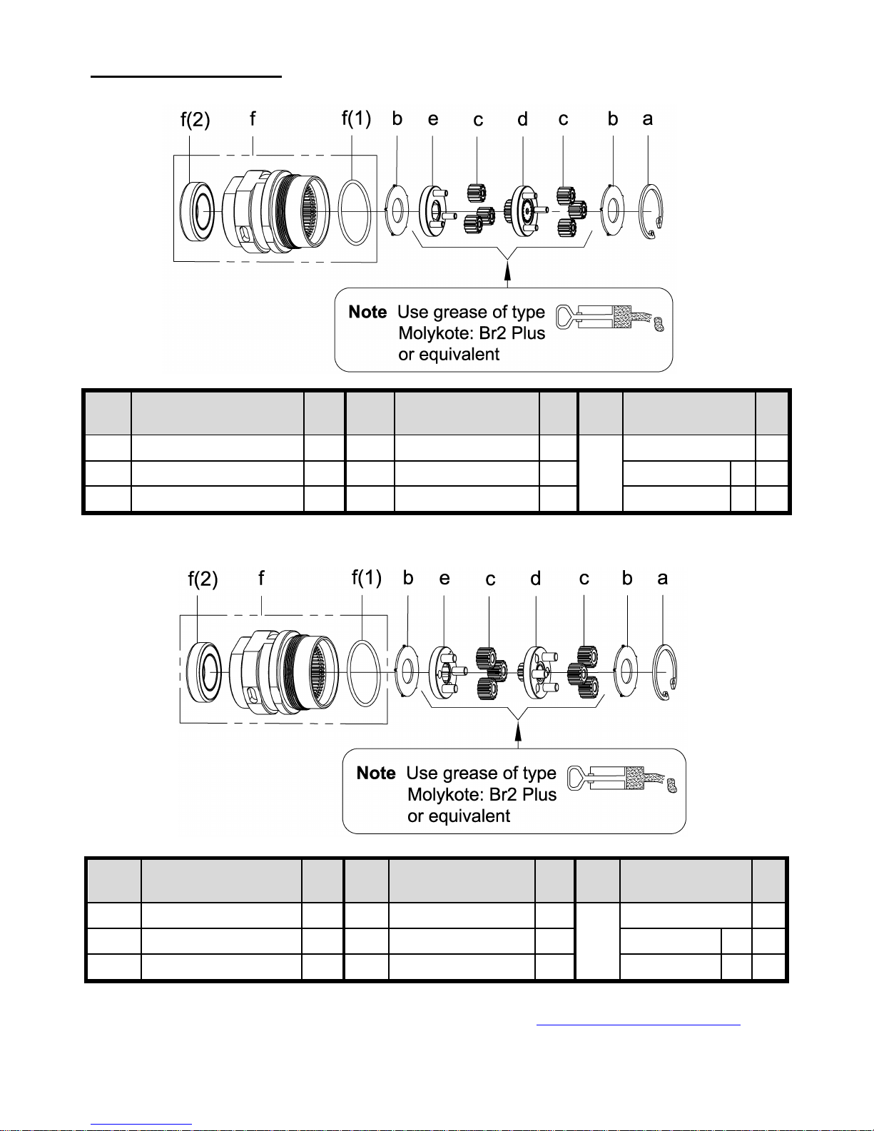
For Model: FLEXC II-3PX
GEAR BOX UNITS
For Model: FLEXC II-6PX
NOTE: This chart only referenced the parts in the drawing, for ordering parts
please consult the parts list per model in our website
www.mountztorque.com
- 13 -
Index
No
Description Q’ty
Index
No
Description Q’ty
Index
No
Description Q’ty
a
Inverted Retaining Ring
1 d
Gear Cage Assembly
1
f
Gear Box Assembly
1
b
Washer
1 e
Gear Plate Assembly
1
(1) O-ring
1
c
Planet Gear
6
(2)Ball Bearing
1
Index
No
Description Q’ty
Index
No
Description Q’ty
Index
No
Description Q’ty
a
Inverted Retaining Ring
1 d
Gear Cage Assembly
1
f
Gear Box Assembly
1
b
Washer
1 e
Gear Plate Assembly
1
(1) O-ring
1
c
Planet Gear
6
(2)Ball Bearing
1
Page 14
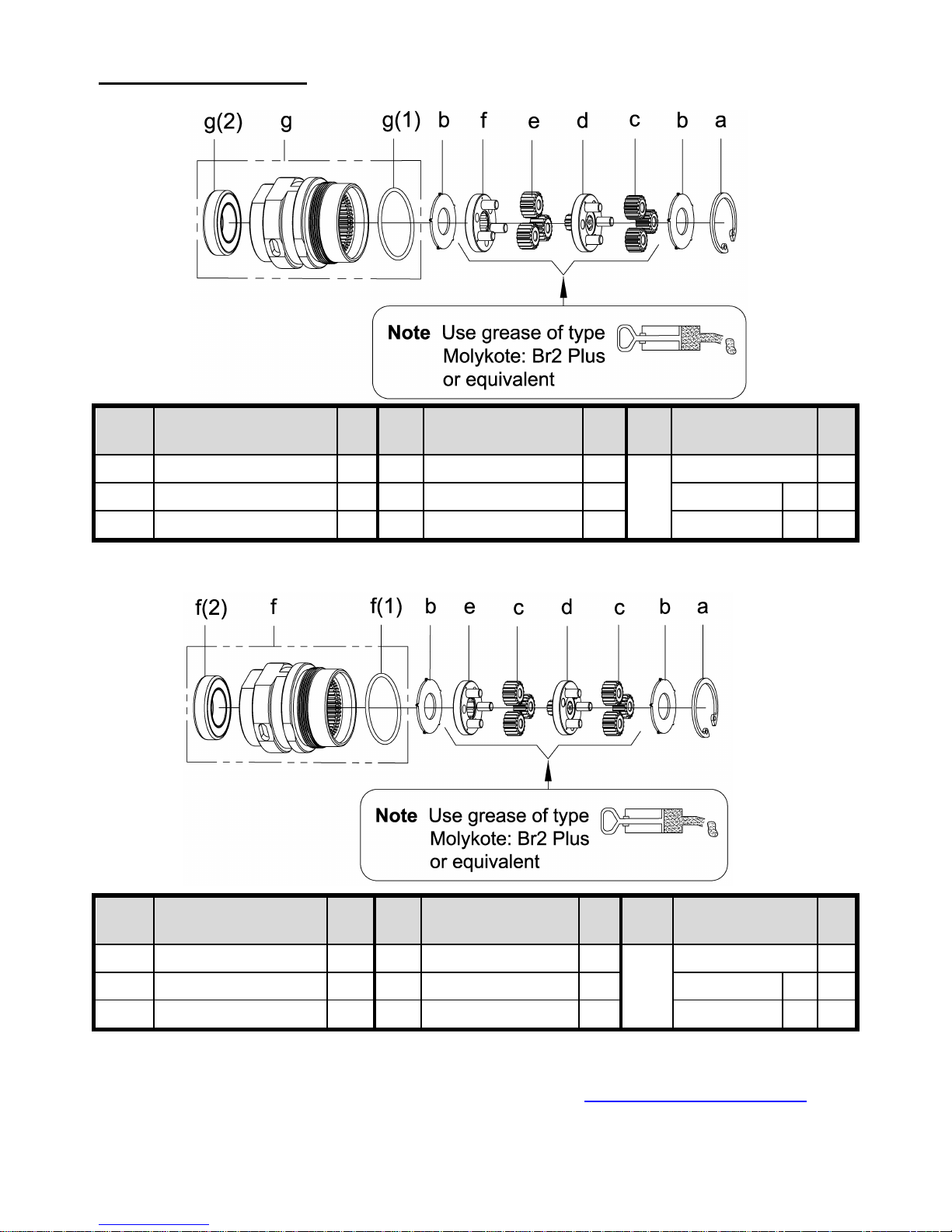
For Model: FLEXC II-9PX
GEAR BOX UNITS
For Model: FLEXC II-12PX
NOTE: This chart only referenced the parts in the drawing, for ordering parts
please consult the parts list per model in our website
www.mountztorque.com
- 14 -
Index
No
Description Q’ty
Index
No
Description Q’ty
Index
No
Description Q’ty
a
Inverted Retaining Ring
1 d
Gear Cage Assembly
1
g
Gear Box Assembly
1
b
Washer
1 e
Planet Gear
3
(1) O-ring
1
c
Planet Gear
3 f
Gear Plate Assembly
1
(2)Ball Bearing
1
Index
No
Description Q’ty
Index
No
Description Q’ty
Index
No
Description Q’ty
a
Inverted Retaining Ring
1 d
Gear Cage Assembly
1
f
Gear Box Asse mbly
1
b
Washer
1 e
Gear Plate Assembly
1
(1) O-ring
1
c
Planet Gear
6
(2)Ball Bearing
1
Page 15
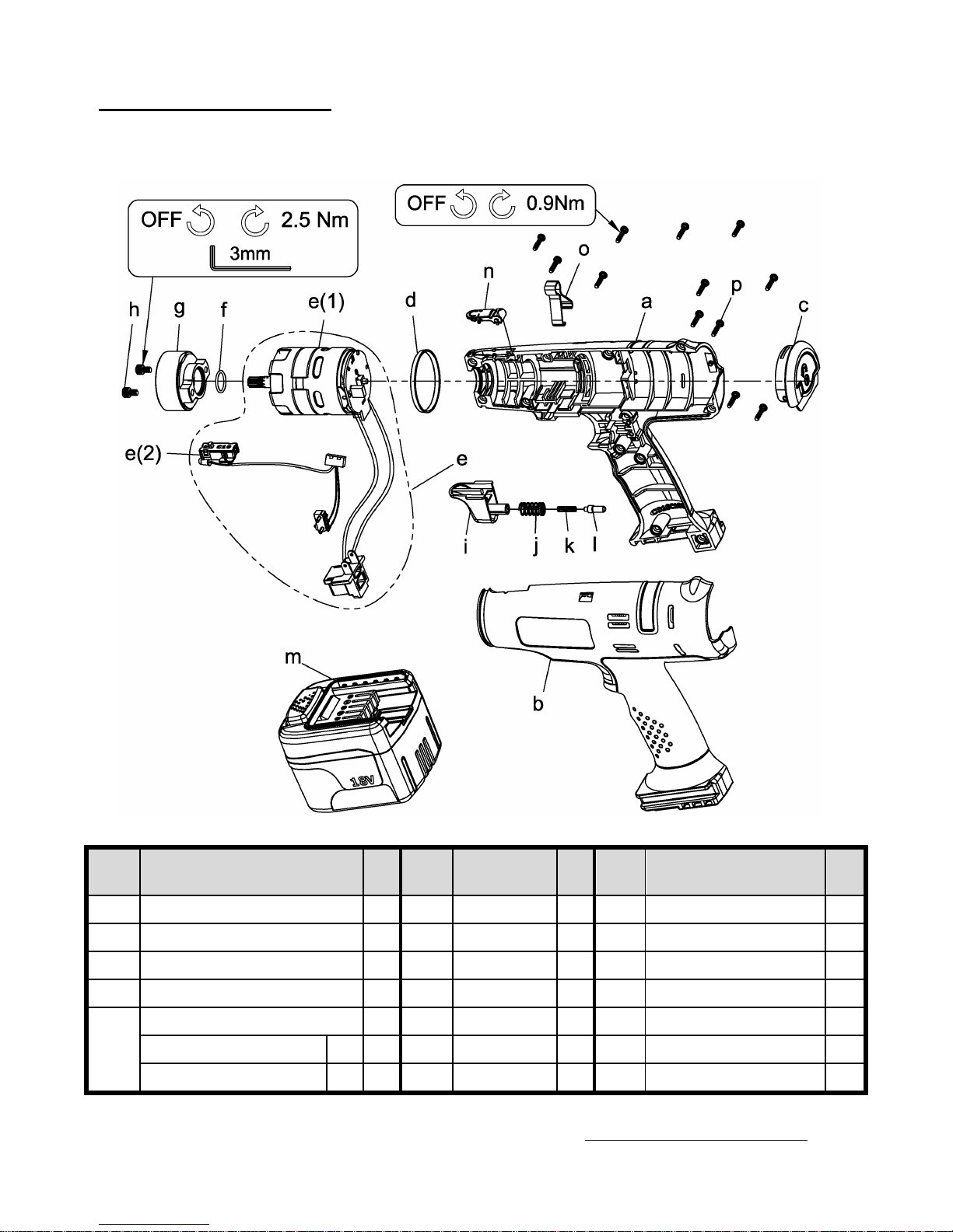
For Models:
HOUSING & MOTOR
FLEXC II-3PX FLEXC II-6PX FLEXC II-9PX FLEXC II-12PX
NOTE: This chart only referenced the parts in the drawing, for ordering parts
please consult the parts list per model in our website
www.mountztorque.com
- 15 -
Index
No
Description Q'ty
Index
No
Description Q'ty
Index
No
Description Q'ty
a Upper Housing 1 f O-Ring 1 m 18V Li-ion 1.5Ah Battery 1
b Lower Housing 1 g Motor Holder 1 n Cover 1
c Cover 1 h Screw 2 o Suspension Bail 1
d Marking Ring 1 i Trigger 1 p Screw 12
e
DC Brushless Motor Assembly 1 j Spring 1
(1) Brushless Motor 1
k Spring 1
(2) Sensor Assembly 1
l Pin Assembly 1
Page 16

Service Centers
USA
Corporate Headquarters & Service Center
1080 North 11th Street, San Jose, CA 95112
Phone: (800) 456-1828 Fax: (408) 292-2733
Distribution & Service Center
19051 Underwood Road, Foley, AL 36535
Phone: (251) 943-4125 Fax: (251) 943-4979
Mexico
Mountz Mexico SA de CV
Ave. Cristobal Colon #15343
Col. Paseos de Chihuahua
Chihuahua, Chih. Mexico CP 31125
Phone: (614) 481-0023 Fax: (614) 481-0053
For more torque products, visit
www.mountztorque.com
For fasteners visit www.mrmetric.com
- 16 -
 Loading...