

Flexport HF2211 User Manual
HF2211 Serial Server Device User Manual
http://www.iotworkshop.com - 1 -
HF2211
Serial Server Device User Manual
V 1.1
Overview of Characteristic
MIPS MCU with 4MB Flash and 8MB SRAM. Run on eCos
Support TCP/IP/Telnet /Modbus TCP Protocol
Support RS232/RS422/RS485 to Ethernet/Wi-Fi Conversion, Serial Speed Upto 460800 bps
Support STA/AP/AP+STA Mode
Support Router or Bridge Network Working Mode.
Support 10/100M Ethernet Auto-Negotiation
Support Easy Configuration Through a Web Interface or PC IOTService Tool
Support Security Protocol Such As SSL/AES/DES3
Support Web OTA Wirelss Upgrade
Wide DC Input 5~36VDC or 9~50VDC
Size: 95 x 65 x 25 mm (L x W x H)
FCC/CE/RoHS Certificated

HF2211 Serial Server Device User Manual
http://www.iotworkshop.com - 2 -
TABLE OF CONTENTS TABLE OF CONTENTS
TABLE OF CONTENTS TABLE OF CONTENTS ........................................................................... 2
LIST OF FIGURES ............................................................................................................................ 5
LIST OF TABLES ............................................................................................................................. 7
HISTORY ........................................................................................................................................... 7
1. PRODUCT OVERVIEW ........................................................................................................ 8
1.1. General Description ......................................................................................................... 8
1.2. Device Features ............................................................................................................... 8
1.3. Device Paremeters ........................................................................................................... 9
1.4. Key Application ..............................................................................................................10
2. HARDWARE INTRODUCTION ......................................................................................... 11
2.1. Pins Definition ................................................................................................................12
2.2. RS232 Interface ..............................................................................................................14
2.3. RS485 Interface ..............................................................................................................14
2.4. RS422 Interface ..............................................................................................................14
2.5. RJ45 Interface ................................................................................................................15
2.6. Mechanical Size .............................................................................................................15
2.7. Rail Mounting .................................................................................................................16
2.8. Order Information ..........................................................................................................16
2.9. Package Information ......................................................................................................17
3. FUNCTIONAL DESCRIPTION .......................................................................................... 18
3.1. Basic Network Protocol .................................................................................................18
3.2. Wireless Network ................................................................................................................18
3.2.1. AP Network ....................................................................................................................... 19
3.2.2. STA Wireless Network ..................................................................................................... 20
3.2.3. AP+STA Wireless Network .............................................................................................. 20
3.2.5. IOTService Software ........................................................................................................ 22
3.2.6. Webpage Configuration ................................................................................................... 22
3.3. Ethernet Interface Function ..............................................................................................23
3.3.1. Ethernet Port with Wi-Fi ................................................................................................... 23
3.3.2. Ethernet Interface Function(Router) ............................................................................... 25
3.3.3. Ethernet Port Function(Bridge) ....................................................................................... 26
3.4. Working Mode ......................................................................................................................27
3.4.1. Transparent Transmission Mode .................................................................................... 27
3.4.2. TCP Server ........................................................................................................................ 28
3.4.3. HTTP Mode ....................................................................................................................... 29
3.4.4. Telnetd Mode ................................................................................................................... 31
3.5. AES/DES3/TLS Data Encryption ........................................................................................32
3.6. Keepalive ..............................................................................................................................33
3.7. Timeout ................................................................................................................................33
3.8. Route Setup .........................................................................................................................34

HF2211 Serial Server Device User Manual
http://www.iotworkshop.com - 3 -
3.9. UART Frame Scheme ..........................................................................................................35
3.9.1. UART Free-Frame ............................................................................................................ 35
3.9.2. UART Auto-Frame ........................................................................................................... 35
3.9.3. Tag Function ................................................................ .................................................... 36
3.10. Modbus Protocol ...............................................................................................................36
3.11. Cli Command .....................................................................................................................37
3.12. UART Flow Control and RS485 Function .......................................................................37
3.13. Firmware Upgrade .............................................................................................................38
3.14. Web Page Function ...........................................................................................................39
3.15. Auto-IP Function ...............................................................................................................39
3.16. NTP Function .....................................................................................................................39
3.17. Heartbeat Function ...........................................................................................................40
3.18. UART Fast Config..............................................................................................................40
3.19. Other Function...................................................................................................................40
4. CLI COMMAND NOTES ....................................................................................................... 42
4.1. Working Mode ................................................................................................................42
4.1.1. Switch Transparent Transmission Mode to Cli Command Mode .................................... 42
4.2. Cli Command Overview .................................................................................................43
4.2.1. Cli Command Format ...................................................................................................... 46
4.2.1.1. Show Command ........................................................................................................... 46
4.2.1.2. SYS Directory ............................................................................................................... 47
4.2.1.3. SYS/Auth Directory ...................................................................................................... 47
4.2.1.4. SYS/Auth/User Command ............................................................................................ 47
4.2.1.5. SYS/Auth/Password Command ................................................................................... 48
4.2.1.6. SYS/Network Directory ................................................................................................. 48
4.2.1.7. SYS/Network/Show Command .................................................................................... 48
4.2.1.8. SYS/Network/DHCP Command ................................................................................... 48
4.2.1.9. SYS/Network/DNS Command ...................................................................................... 48
4.2.1.10. SYS/Network/Mode Command................................................................................... 49
4.2.1.11. SYS/Network/Hostname Instruction ........................................................................... 49
4.2.1.12. SYS/Telnet Instruction ................................................................................................ 49
4.2.1.13. SYS/Web Instruction .................................................................................................. 50
4.2.1.14. SYS/MAC Instruction .................................................................................................. 50
4.2.1.15. SYS/JCMD Instruction ................................................................................................ 50
4.2.1.16. SYS/NTP Instruction................................................................................................... 50
4.2.1.17. UART Directory .......................................................................................................... 51
4.2.1.18. UART/Show Instruction .............................................................................................. 51
4.2.1.19. UART/Baudrate Instruction......................................................................................... 51
4.2.1.20. UART/Databits Instruction .......................................................................................... 51
4.2.1.21. UART/Stopbits Instruction .......................................................................................... 52
4.2.1.22. UART/Parity Instruction .............................................................................................. 52
4.2.1.23. UART/Buf Directory .................................................................................................... 52
4.2.1.24. UART/Buf/Bufsize Instruction ..................................................................................... 52
4.2.1.25. UART/Buf/GapTime Instruction .................................................................................. 53

HF2211 Serial Server Device User Manual
http://www.iotworkshop.com - 4 -
4.2.1.26. UART/Buf/FlowCtrl Command.................................................................................... 53
4.2.1.27. UART/Buf/SWFlowCtrl Command .............................................................................. 53
4.2.1.28. UART/Cli-Getin Command ......................................................................................... 54
4.2.1.29. UART/Cli-WaitTime Command................................................................................... 54
4.2.1.30. UART/Proto command ............................................................................................... 54
4.2.1.31. UART/Frame Directory ............................................................................................... 55
4.2.1.32. UART/Frame/FrameLen Command ........................................................................... 55
4.2.1.33. UART/Frame/FrameTime Command ......................................................................... 55
4.2.1.34. UART/Frame/Tag Command...................................................................................... 55
4.2.1.35. UART/Edit Command ................................................................................................. 56
4.2.1.36. UART/Clean Command .............................................................................................. 56
4.2.1.37. SOCK Directory .......................................................................................................... 56
4.2.1.38. SOCK/Show Command .............................................................................................. 56
4.2.1.39. SOCK/New Command................................................................................................ 56
4.2.1.40. SOCK/netp directory................................................................................................... 58
4.2.1.41. SOCK/netp/clean Command ...................................................................................... 58
4.2.1.42. DATA Directory........................................................................................................... 59
4.2.1.43. Restart Command ...................................................................................................... 59
4.2.1.44. Reload Instruction....................................................................................................... 59
4.2.1.45. WIFI Catolog............................................................................................................... 59
4.2.1.46. WIFI/Show Command ................................................................................................ 59
4.2.1.47. WIFI/Mode Command ................................................................................................ 60
4.2.1.48. WIFI/Status Command ............................................................................................... 60
4.2.1.49. WIFI/Scan Command ................................................................................................. 60
4.2.1.50. Exit Command ............................................................................................................ 61
4.2.1.51. Quit Command ........................................................................................................... 61
4.2.1.52. FwUpgrade Instruction ............................................................................................... 61
APPENDIX A:REFERENCES ..................................................................................................... 62
A.1.Test Tools ..........................................................................................................................62
A.2.Quick Start Manual ...........................................................................................................62
APPENDIX B:TELNET COMMUNICATION FUNCTION ............................................................. 63
B.1.Telnet Use Scene: .............................................................................................................63
B.2.Telnet Features: ................................................................................................................63
B.3.Telnet Usage:.....................................................................................................................63
APPENDIX C: CONTACT INFORMATION ............................................................................... 67

HF2211 Serial Server Device User Manual
http://www.iotworkshop.com - 5 -
LIST OF FIGURES
Figure 1. HF2211 Appearance ............................................................................................................................... 11
Figure 2. HF2211 Interface ..................................................................................................................................... 12
Figure 3. HF2211 Side View ................................................................................................................................... 13
Figure 4. RS232 Pin Defination(Male/Needle Type) ............................................................................................... 14
Figure 5. HF2211 RS422 Connection ..................................................................................................................... 15
Figure 6. RJ45 Pin Defination ................................................................................................................................. 15
Figure 7. HF2211 Mechanical Dimension ............................................................................................................... 16
Figure 8. HF2211 Rail ............................................................................................................................................ 16
Figure 9. HF2211 Product Order Information ......................................................................................................... 17
Figure 10. HF2211 Software Protocol Structure ..................................................................................................... 18
Figure 11. HF2211 Function Structure ................................................................................................................... 19
Figure 12. General AP Network .............................................................................................................................. 19
Figure 13. STA Application ..................................................................................................................................... 20
Figure 14. AP+STA Wireless Network .................................................................................................................... 21
Figure 16. Configure Wi-Fi Parameter .................................................................................................................... 22
Figure 17. STA Scan Parameter............................................................................................................................. 22
Figure 18. Configure the Wi-Fi Parameter ................................................................................................ .............. 23
Figure 19. STA Scan .............................................................................................................................................. 23
Figure 20. Ethernet Interface Function ................................................................................................................... 24
Figure 21. Ethernet Interface Function(Router) ...................................................................................................... 25
Figure 22. Ethernet Port Function(Bridge) .............................................................................................................. 26
Figure 23. Transparent data transmission example ................................................................................................ 28
Figure 24. TCP Server data transmission example ................................................................................................ 28
Figure 25. Multi Socket data transmission example ............................................................................................... 28
Figure 26. Webpage set up multi Socket channel .................................................................................................. 29
Figure 27. IOT Manager Software Configure .......................................................................................................... 29
Figure 28. Web Page Configure ............................................................................................................................. 30
Figure 29. HTTP transmit example ......................................................................................................................... 30
Figure 30. IOTService Software Configure Protocol ............................................................................................... 31
Figure 31. Web page configure protocol ................................................................................................................. 31
Figure 32. Telnet details example ........................................................................................................................... 32
Figure 33. IOTService Software Configure Encryption ........................................................................................... 32
Figure 34. Web Page Configure Encryption ........................................................................................................... 33
Figure 35. Web Page Config Keepalive .................................................................................................................. 33
Figure 36. Web Page Configure Timeout ............................................................................................................... 34
Figure 37. Route function setup example ............................................................................................................... 34
Figure 38. Route Function Data Flow Example ...................................................................................................... 35
Figure 39. UART free-frame function ...................................................................................................................... 35
Figure 40. UART Auto-Frame Function .................................................................................................................. 36
Figure 41. UART Auto-Frame Function .................................................................................................................. 36
Figure 42. UART Auto-Frame Tag Function ........................................................................................................... 36
Figure 43. UART Modbus Function ........................................................................................................................ 37
Figure 44. Cli Command Setting ............................................................................................................................. 37

HF2211 Serial Server Device User Manual
http://www.iotworkshop.com - 6 -
Figure 45. UART Flow Control................................................................................................................................ 37
Figure 46. UART Half Duplex Function .................................................................................................................. 38
Figure 47. External web page ................................................................................................................................. 38
Figure 48. Internal web page .................................................................................................................................. 38
Figure 49. Web Page Function Setting ................................................................................................................... 39
Figure 50. AUTO-IP Connection ............................................................................................................................. 39
Figure 51. IOTService Tools NTP Setting .............................................................................................................. 40
Figure 52. Cli Command NTP Setting and Query ................................................................................................... 40
Figure 53. Heartbeat Function ................................................................................................................................ 40
Figure 54. Other Function ....................................................................................................................................... 41
Figure 55. HF2211 Default: UART Parameters ...................................................................................................... 42
Figure 56. Switch Transparent Transmission Mode to Cli Command Mode ........................................................... 43
Figure 57. Cli Command Root Directory ................................................................................................................. 43
Figure 58. Cli Command SYS Tree ........................................................................................................................ 44
Figure 59. Cli Command UART Tree ...................................................................................................................... 44
Figure 60. Cli Command SOCK Tree ..................................................................................................................... 45
Figure 61. Cli Other Command ............................................................................................................................... 46

HF2211 Serial Server Device User Manual
http://www.iotworkshop.com - 7 -
LIST OF TABLES
Table 1. HF2211 Technical Specifications ............................................................................................................... 9
Table 2. HF2211 Interface Definition ...................................................................................................................... 13
Table 3. RS232 Interface ........................................................................................................................................ 14
Table 4. RJ45 Interface .......................................................................................................................................... 15
HISTORY
Ed. V1.0 08-03-2017 First Version
Ed. V1.1 06-07-2017 Update to 1.09j version. IOTService Update to 2.07e.

HF2211 Serial Server Device User Manual
http://www.iotworkshop.com - 8 -
1. PRODUCT OVERVIEW
1.1. General Description
The HF2211 provides RS232/RS485/RS422 interface to Ethernet/Wi-Fi connectivity to web enable
any device. The HF2211 integrate TCP/IP controller, memory, 10/100M Ethernet transceiver, highspeed serial port and integrates a fully developed TCP/IP network stack and ECos OS.The HF2211
also includes an embedded web server used to remotely configure, monitor, or troubleshoot the
attached device.
The HF2211 using highly integrated hardware and software platform,It has been optimized for all kinds
of applications in the industrial control, smart grid , personal medical application and remote control
that have lower data rates, and transmit or receive data on an infrequent basis.
The HF2211 integrates all serial to Ethernet functionality with 95 x 65 x 25mm size..
1.2. Device Features
MIPS MCU with 4MB Flash and 8MB SRAM
Support ECos Operation System
Support TCP/IP、UDP、DHCP、DNS、HTTP Server/Client、ARP、BOOTP、AutoIP、ICMP、
Telnet、FTP、TFTP、uPNP、NTP、ModbusTCP Protocol
Support Serial to 10/100M Ethernet Conversion, Serial Speed Upto 460800 bps
Support 10/100M Ethernet Auto-Negotiation
Support STA/AP/AP+STA Wireless Working Mode
Support Easy Configuration Through a Web Interface
Support Security Protocol Such As SSL/AES/DES3
Support Web Wireless Upgrade
Wide 5~36VDC or 9~50VDC Power Supply
Size: 95 x 65 x 25mm (L x W x H)
FCC/CE/RoHS Certificated

HF2211 Serial Server Device User Manual
http://www.iotworkshop.com - 9 -
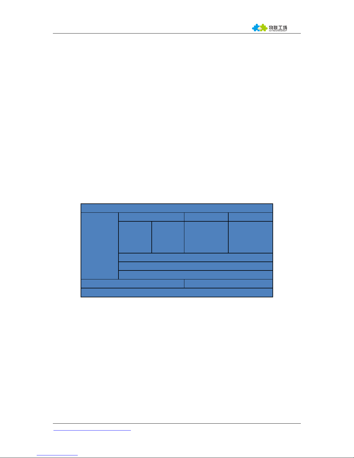
1.3. Device Paremeters
Table 1. HF2211 Technical Specifications
Item
Parameters
System Information
Processor/Frequency
MIPS/320MHz
Flash/SDRAM
4MB/8MB
Operating System
ECos
Ethernet Port
Port Number
1 RJ45
Interface Standard
10/100 Base-T Auto-Negotiation
Protection
8KV Isolation
Transformer
Integrated
Network Protocol
IP,TCP,UDP,DHCP,DNS,HTTP Server/Client,ARP,
BOOTP, AutoIP, ICMP,Web socket, Telnet, FTP,TFTP,
uPNP, NTP, SNMP,Modbus TCP
Security Protocol
SSL v3
AES 128Bit
DES3
IPV6 Support
Plan to Support
Wi-Fi Interface
Standard
802.11 b/g/n
Frequency
2.412GHz-2.484GHz
Network Mode
STA/AP/STA+AP
Security
WEP/WPAPSK/WPA2PSK
Encryption
WEP64/WEP128/TKIP/ AES
Tx Power
802.11b: +20dBm(Max.)
802.11g: +18dBm(Max.)
802.11n: +15dBm(Max.)
Rx Sensitive
802.11b: -89dBm
802.11g: -81dBm
802.11n: -71dBm
Antenna
3dBi Stick Antenna
Serial Port
Port Number
1 RS232/RS485/RS422
Interface Standard
RS232: DB9
RS485/RS422: 5.08mm connector
Support one channel of RS232/RS422/RS485.
Data Bits
8
Stop Bit
1,2
Check Bit
None,Even,Odd,Space,Mark
Baud Rate
TTL: 600 bps~460800 bps
Flow Control
No Flow control
Hardware RTS/CTS、DSR/DTR
Software Xon/ Xoff flow control
Software

HF2211 Serial Server Device User Manual
http://www.iotworkshop.com - 10 -
Web Pages
Http Web Configuration
Customization of HTTP Web Pages
Configuration
Web
CLI
XML import
Telnet
IOTService PC Software
Firmware Upgrade
Web
SDK For Dev.
Plan to Provide
Basic Parameter
Size
95 x 65 x 25 mm
Operating Temp.
-45 ~ 70°C
Storage Temp.
-45 ~ 105°C, 5 ~ 95% RH(no condensation)
Input Voltage
5~36VDC or 9~50VDC
Working Current
~200mA
Power
<700mW
Other Information
Certificate
CE, FCC, RoHS
1.4. Key Application
The HF2211 device connects serial device to Ethernet networks using the TCP/IP protocol:
Remote equipment monitoring
Asset tracking and telemetry
Security Application
Industrial sensors and controls
Medical devices
ATM machines
Data collection devices
Universal Power Supply (UPS) management units
Telecommunications equipment
Data display devices
Handheld instruments
Modems
Time/attendance clocks and terminals
HF2211 Serial Server Device User Manual
http://www.iotworkshop.com - 11 -
2. HARDWARE INTRODUCTION
The HF2211 unit is a complete solution for serial port device connecting to network. This powerful
device supports a 10/100BASE-T Ethernet connection, a reliable and proven operating system stored
in flash memory, an embedded web server, a full TCP/IP protocol stack,and standards-based (AES)
encryption.
Through Ethernet cable connect router with HF2211 serial server for data transfer, which makes the
data transformation very simple. HF2211 meet EMC Class B security level,It can pass every countries
relevant certification test
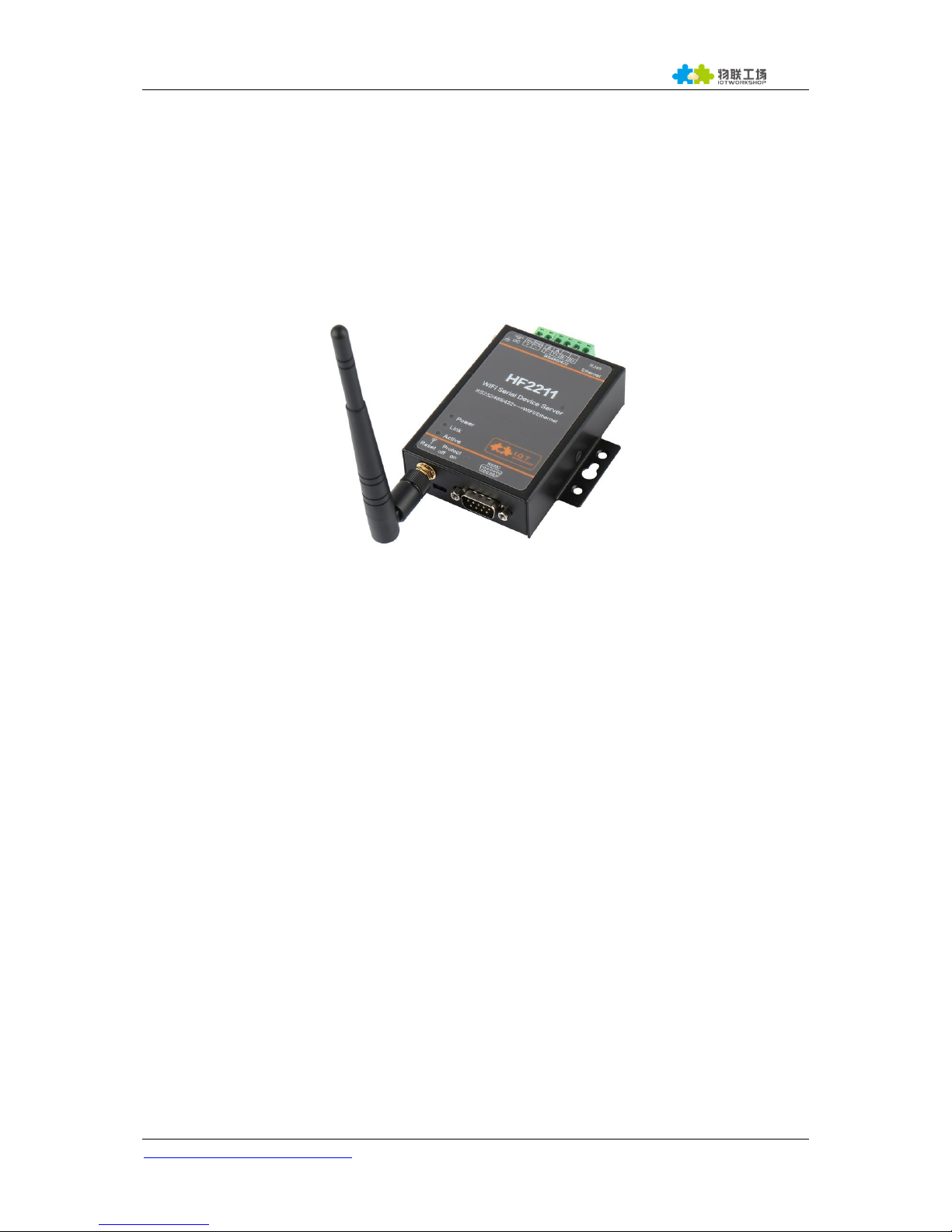
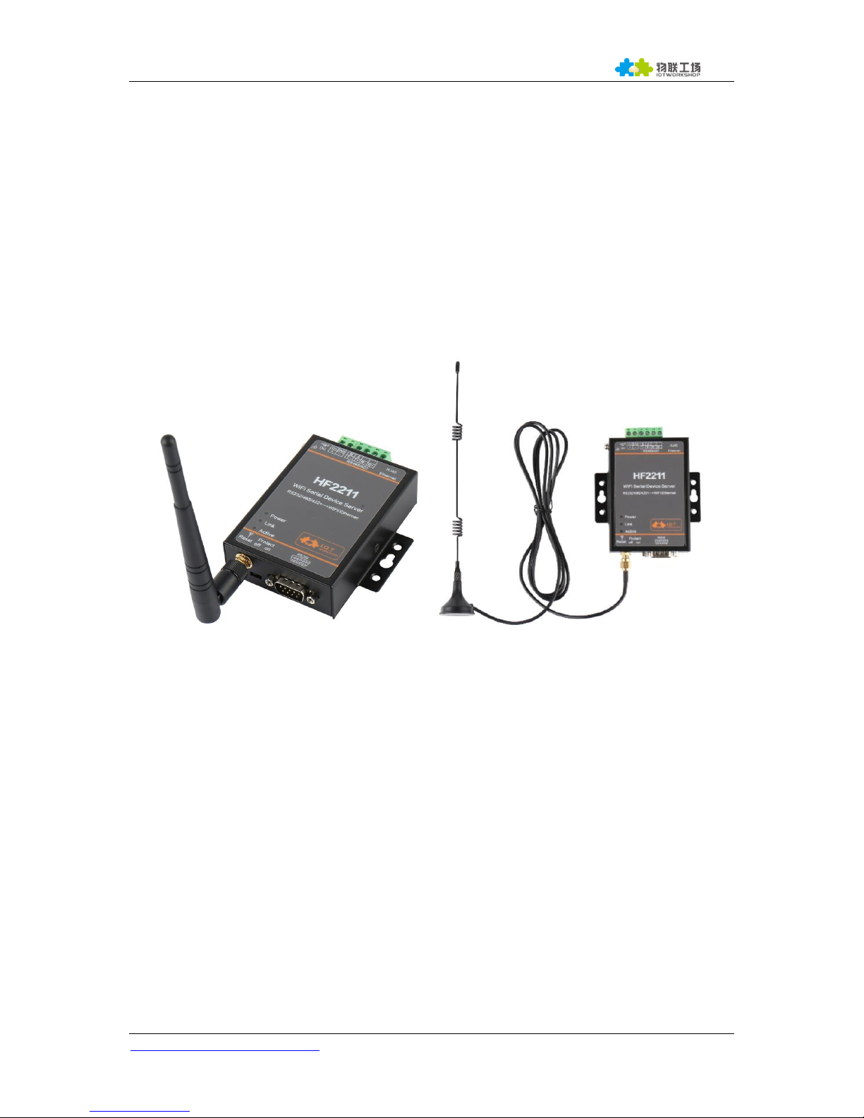
Figure 1. HF2211 Appearance

HF2211 Serial Server Device User Manual
http://www.iotworkshop.com - 12 -
2.1. Pins Definition
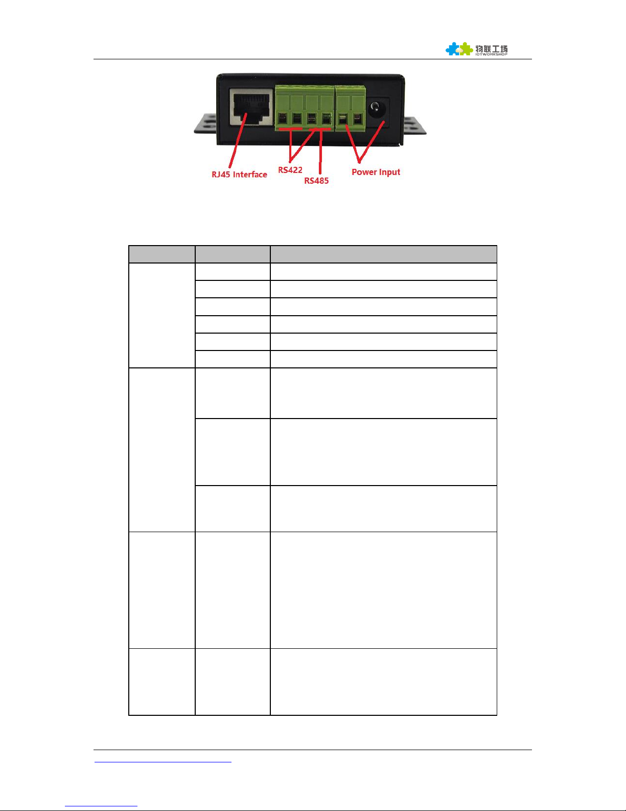
Figure 2. HF2211 Interface
HF2211 Serial Server Device User Manual
http://www.iotworkshop.com - 13 -
Figure 3. HF2211 Side View
Table 2. HF2211 Interface Definition
Function
Name
Description
External
Interface
RJ45 Ethernet
10/100M Ethernet
SMA
Antenna SMA Interface
RS232
RS232 Communication
RS485/RS422
RS485/RS422 Communicaton
Earth
Protect Earth
DC Input
DC Power 5~36V Input or 9~50VDC
LED
Indicator
Power
Internal Power Supply Indicator
On:Power is OK
Off:Power is NG
Link
Connection Indicator
On: Ethernet connection or Wi-Fi STA
connection is OK
Off: No Ethernet connection
Active
Data transfer Indicator
On:Data is transfering.
Off:No data transfer
Button
Reset
Restore to factory setting
Long press this button for 3seconds and loose
it to restore parameters to factory setting.
Note:
This button of early product is just restart. The
hardware has been modified to factory setting
now.
Switch
Protect
Device parameter protect
On: Enable protect, working parameter can not
be modified.
Off: Disable protect.
HF2211 Serial Server Device User Manual
http://www.iotworkshop.com - 14 -
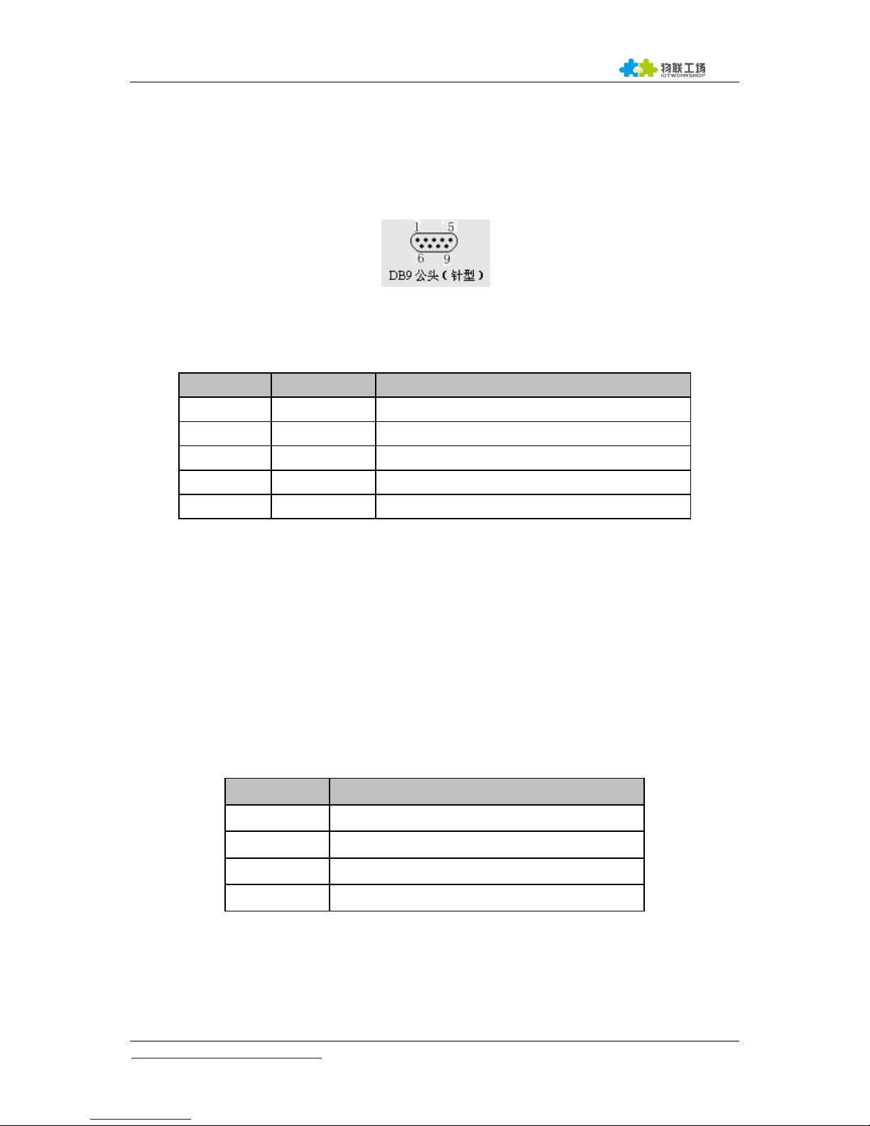
2.2. RS232 Interface
Device serial port is male(needle), RS232 voltage level(can connect to PC directly), Pin Order is
cosistent with PC COM port. Use cross Cable connected with PC(2-3 cross, 7-8 cross, 5-5 direct, 7-8
no connection), see the following table for pin defination.
Figure 4. RS232 Pin Defination(Male/Needle Type)
Table 3. RS232 Interface
Pin Number
Name
Description
2
RXD
Receive Data
3
TXD
Send Data
5
GND
GND
7
RTS
Request to Send
8
CTS
Clear to Send
2.3. RS485 Interface
RS485 use two wire links, A(DATA+), B(DATA-). Connect A(+) to A(+), B(-) to B(-) for communication.
The RS485 interface support maximum 32 485 device, special hardware version can support max 255
device. The cable maximum length is 1200 meters. Need to add 120Ohm terminal resistor for over
300 meters.
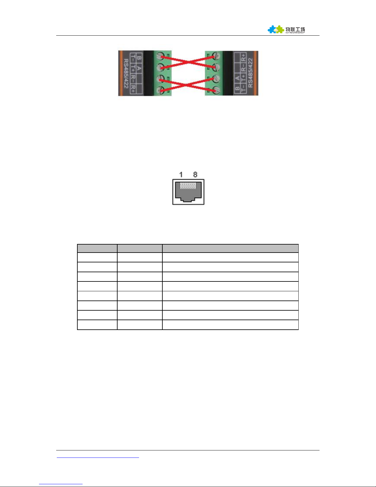
2.4. RS422 Interface
RS422 interface use T+/T-/R+/R-, cross connect to device as the following picture.
Name
Description
TX+
Transfer Data+
TX-
Transfer Data-
RX+
Receive Data+
RX-
Receive Data-
HF2211 Serial Server Device User Manual
http://www.iotworkshop.com - 15 -
Figure 5. HF2211 RS422 Connection
2.5. RJ45 Interface
Ethernet port is 10M/100M adaptive, support AUTO MDI/MDIX which means it support direct
connecting to PC with Ethernet cable.
Figure 6. RJ45 Pin Defination
Table 4. RJ45 Interface
Pin Number
Name
Description
1
TX+
Transfer Data+
2
TX-
Transfer Data-
3
RX+
Receive Data+
4
PHY-VCC
Transformer Tap Voltage
5
PHY-VCC
Transformer Tap Voltage
6
RX-
Receive Data-
7
N.C.
None Connect
8
N.C.
None Connect
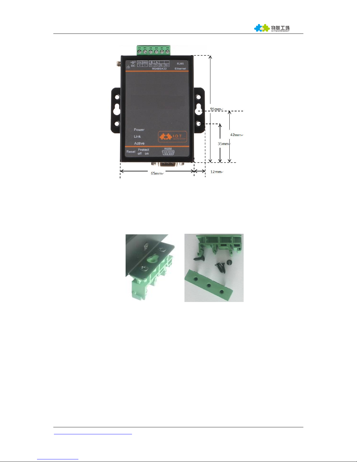
2.6. Mechanical Size
The dimensions of HF2211 are defined as following picture (mm):
HF2211 Serial Server Device User Manual
http://www.iotworkshop.com - 16 -
Figure 7. HF2211 Mechanical Dimension
2.7. Rail Mounting
We support to provide rail for mounting as the following picture.
Figure 8. HF2211 Rail
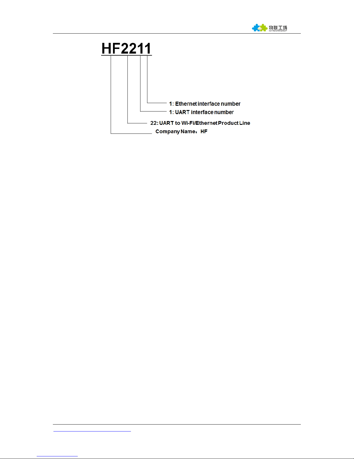
2.8. Order Information
Base on customer detailed requirement, HF2211 provide different configuration version, Details as
below:
HF2211 Serial Server Device User Manual
http://www.iotworkshop.com - 17 -
Figure 9. HF2211 Product Order Information
2.9. Package Information
1 * HF2211
1 * 12V/1A DC adapter
1 * RS232 cable
1 * Ethernet cable
1 * SMA Antenna
HF2211 Serial Server Device User Manual
http://www.iotworkshop.com - 18 -
3. FUNCTIONAL DESCRIPTION
The HF2211 has the following feature:
Connect customer’s device with PC or server via TCP/UDP/Telnet.
Contain a HTTP web server allow user to configure through browser with PC or phone.
Have multi-programmable I/O pins used to monitor or control device directly.
3.1. Basic Network Protocol
The HF2211 device uses the IP address for network communications. If uses the TCP to assure that
no data is lost or duplicated. If use UDP to assure that data can be fast and effective to Destination
address.
Supported protocols include:
ARP, UDP, TCP, ICMP, DHCP, Telnet, DHCP, HTTP Server/Client Web socket
Telnet command configuration, Web server configuration
Security Protocol: TLS, AES, DES3 encryption
HF2211
Application
Programming
Interface
Protocols
Security
Configuration
DHCP
IGMP
WebSocket
DNS/DDNS
TCP/IP
HTTP
SSL/TLS
AES
DES
Web
CLI
Telnet
Log
TCP/UDP
IP/ICMP
Ethernet
FreeRTOS OS
Drivers
Cortex-M3 MCU
Figure 10. HF2211 Software Protocol Structure
3.2. Wireless Network
HF2211 can be set as a wireless STA and AP as well. And logically, it supports two wireless interfaces,
one is used as STA and the other is AP. Other STA devices can join into the wireless network through
AP interface. So the it can provide flexible networking method and network topology. Functions is as
follow:
HF2211 Serial Server Device User Manual
http://www.iotworkshop.com - 19 -
Figure 11. HF2211 Function Structure
<Introductions>
AP: Wireless access point which is the central joint. Usually, wireless router is a AP, other STA
devices can connect with AP to join the network.
STA: Wireless station which is terminal of a wireless network. Such as laptop and pad etc.
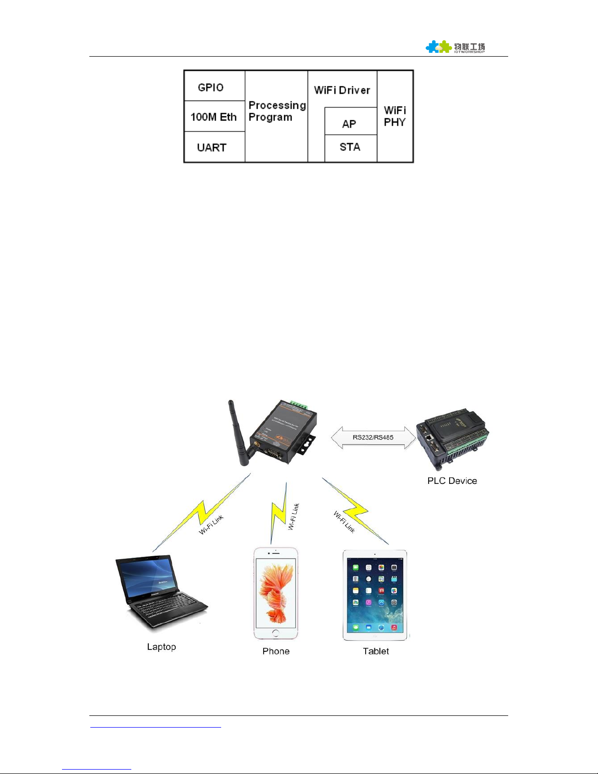
3.2.1. AP Network
HF2211 can construct a wireless network as AP. All the STA devices will consider the AP as the
centre of the wireless network. The mutual communication can be transponded by AP,shown as follow:
Figure 12. General AP Network
HF2211 Serial Server Device User Manual
http://www.iotworkshop.com - 20 -
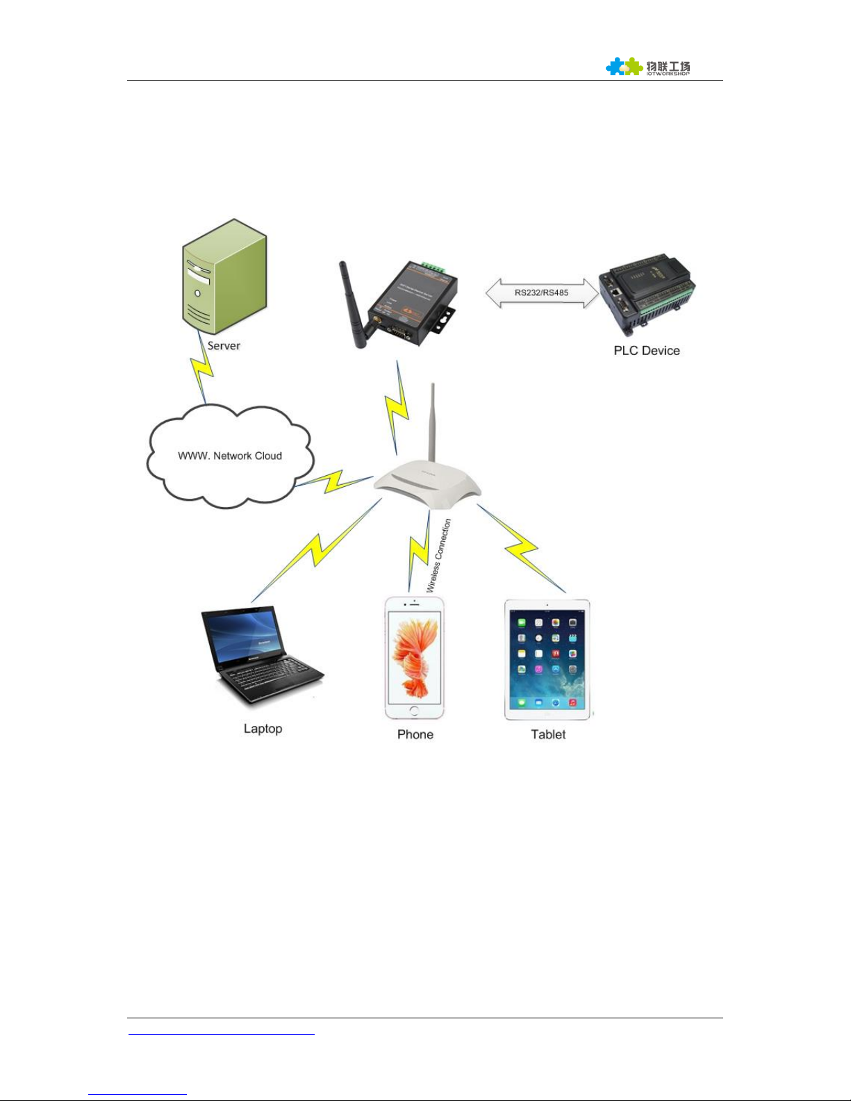
3.2.2. STA Wireless Network
Take the following picture as example. When router works in AP mode, HF2211 connects to the
user’s devices by RS232/RS485 interface. In this topology, the whole wireless network can be easily
stretched.
r
Figure 13. STA Application
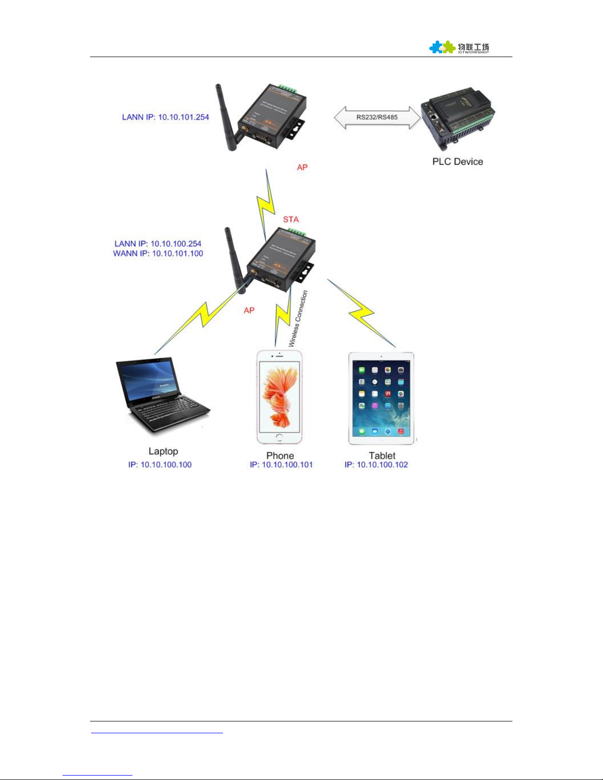
3.2.3. AP+STA Wireless Network
HF2211 can support AP+STA method. It can support AP and STA interface at the same time.Shown
as follow:
HF2211 Serial Server Device User Manual
http://www.iotworkshop.com - 21 -
Figure 14. AP+STA Wireless Network
In this picture, HF2211 open the AP+STA function and the STA interface can be connected to the
remote server by the router. Similarly, the AP interface can also be used. Phone/PAD can be
connected to the AP interface and to control the serial devices or set itself.
Through AP+STA function, it is convenient to use Phone/PAD to monitor the user’s devices and not
change its original settings.
Through AP+STA function, it is convenient to configure the product.And it solves the problem that the
formal product can only configure by serial port.
Notes that:
 Loading...