

Page 1
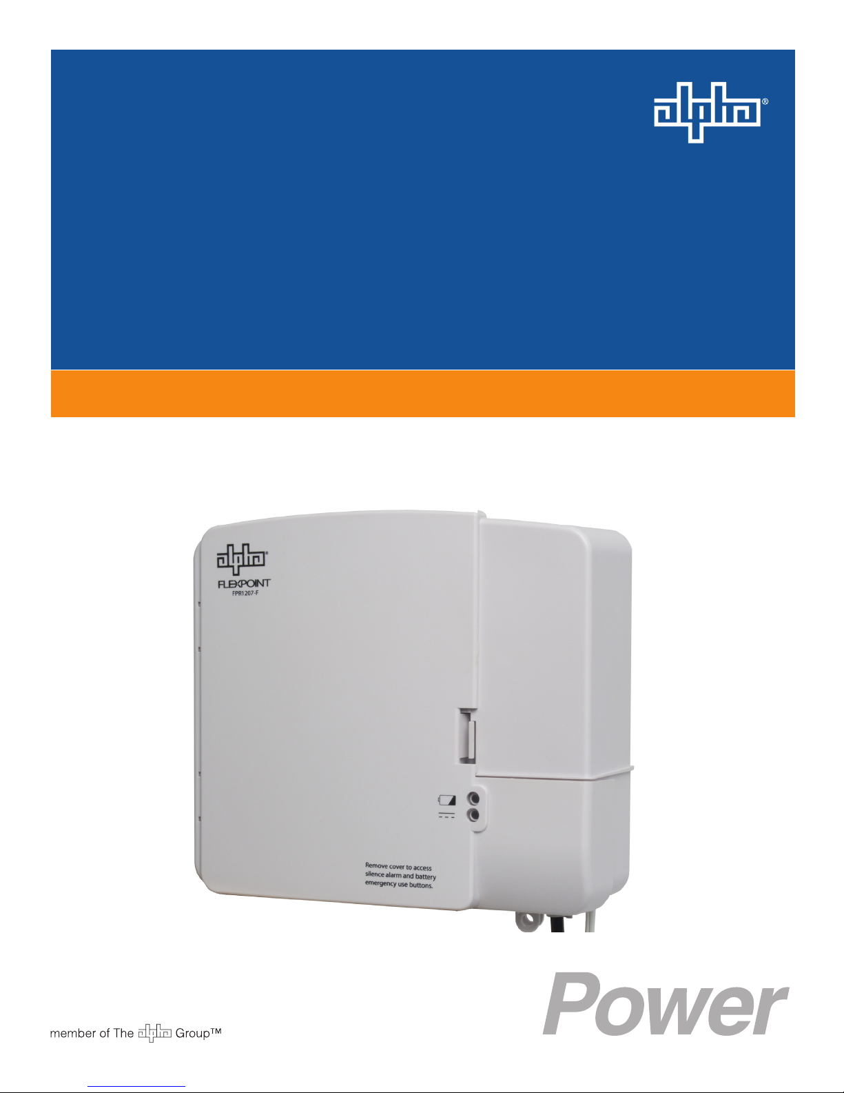
FlexPoint FPR1207-F
Technical Manual
FlexPoint FPR1207-F 7W UPS
Effective: February 2014
Page 2

Alpha Technologies
Power
®
Page 3

FlexPoint FPR1207-F
Technical Manual
010-344-B1-001, Rev. A
Effective Date: February 2014
Copyright 2014
Alpha Technologies, Inc.
member of The Group
NOTE:
Photographs contained in this manual are for illustrative purposes only. These photographs may not match
your installation.
NOTE:
Operator is cautioned to review the drawings and illustrations contained in this manual before proceeding. If
there are questions regarding the safe operation of this powering system, please contact Alpha Technologies
or your nearest Alpha representative.
NOTE:
Alpha shall not be held liable for any damage or injury involving its enclosures, power supplies, generators,
batteries, or other hardware if used or operated in any manner or subject to any condition not consistent with
its intended purpose, or if installed or operated in an unapproved manner, or improperly maintained.
TM
To contact Alpha Technologies:
Visit www.alpha.com
or
For general product information and customer service (7 AM to 5 PM, Pacic Time), call
7 AM to 5 PM, Pacic Time or 24/7 emergency support
To report errors in this document, send email to:
1-800-863-3930,
For complete technical support, call
1-800-863-3364
3
Page 4

Table of Contents
Safety Notes .......................................................................................................................... 6
1.0 Introduction ................................................................................................................. 7
1.1 List of Terms ..................................................................................................... 7
1.2 Theory of Operation ......................................................................................... 7
1.3 System Features .............................................................................................. 8
1.4 Options............................................................................................................. 9
1.5 Items Included ................................................................................................. 9
2.0 Installation ................................................................................................................ 10
2.1 Installation and Connection............................................................................ 10
2.2 Battery Installation / Replacement Procedure................................................ 12
3.0 Operation ................................................................................................................. 13
3.1 Power On ....................................................................................................... 13
3.0 Operation, continued ............................................................................................... 14
3.2 Audible Alarms and Visual Indicators ............................................................. 14
3.3 Battery ............................................................................................................ 14
3.4 Operational Modes......................................................................................... 15
3.4.1 Normal Mode ....................................................................................... 15
3.4.2 Back-Up Mode ................................................................................... 15
3.4.3 Emergency Use .................................................................................. 15
3.4.4 Charging Mode ..................................................................................... 15
4.0 Specications............................................................................................................ 16
4
010-344-B1-001 Rev. A (2/2014)
Page 5

Figures and Tables
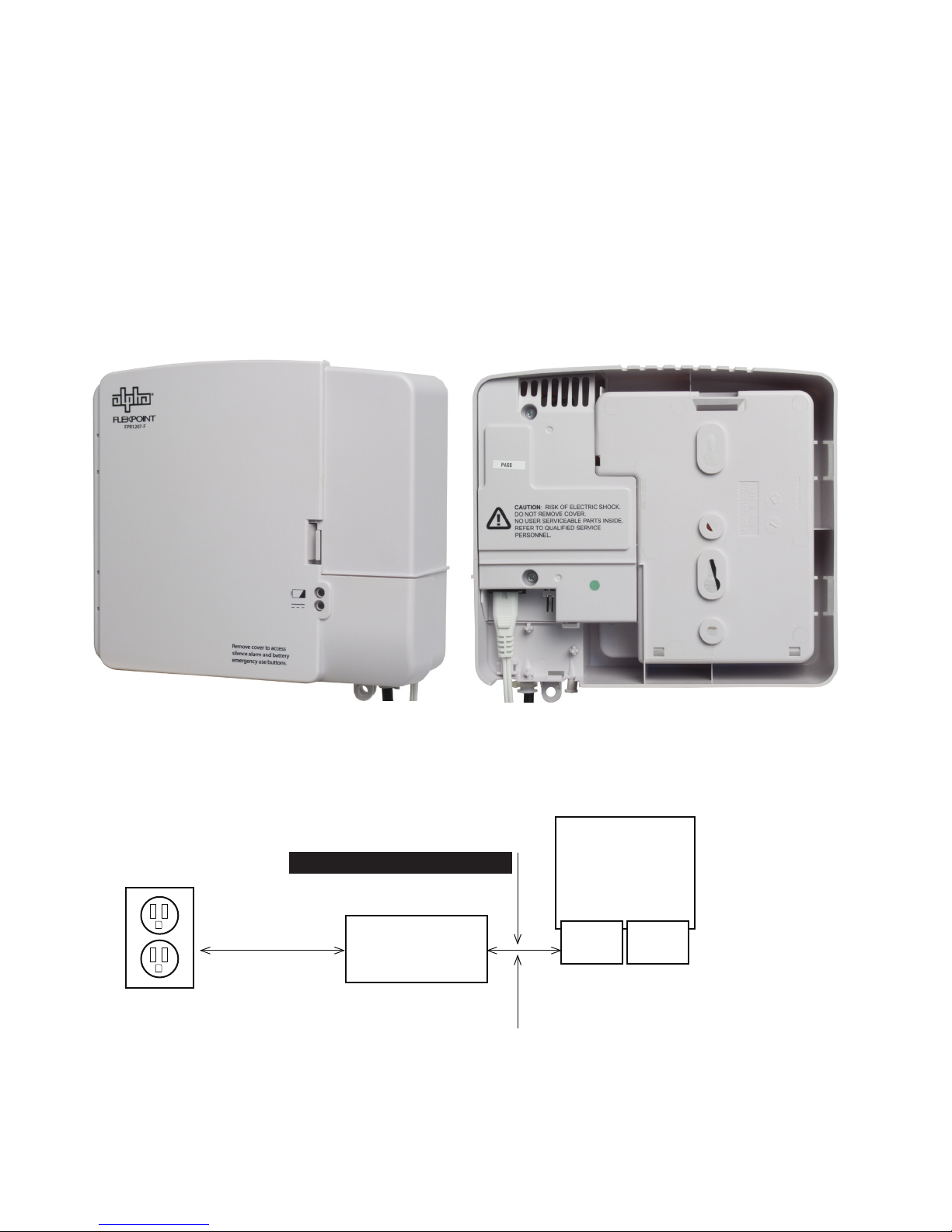
Fig. 1-1, Front View .................................................................................................... 8
Fig. 1-2, Rear View ..................................................................................................... 8
Fig. 1-3, System Block Diagram ................................................................................. 8
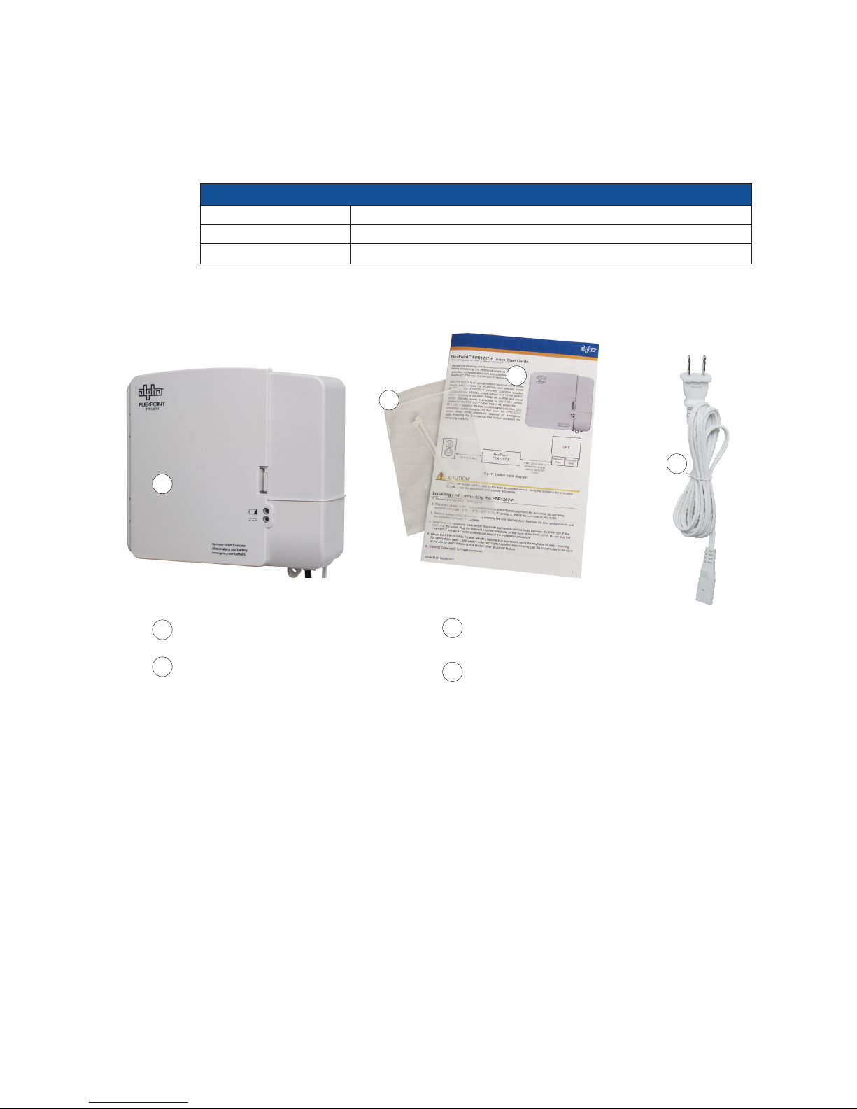
Fig. 1-4, Items Included with each unit ....................................................................... 9
Fig. 2-1, Unit Dimensions ......................................................................................... 10
Fig. 2-2, FPR1207-F Output Cables and Connections ..............................................11
Fig. 2-3, Function List (Inside Lid of Enclosure) ........................................................11
Fig. 2-4, Battery Terminals ........................................................................................ 12
Fig. 2-5, Battery Compartment, FPR1207-F ............................................................. 12
Fig. 2-6, Completed Installation ................................................................................ 12
Fig. 3-1, Controls and Indicators............................................................................... 13
Table 3-1, Audible Alarm and Visual Indicators ......................................................... 14
010-344-B1-001 Rev. A (2/2014)
5
Page 6
Safety Notes
Review the drawings and illustrations contained in this manual before proceeding. If there are any questions
regarding the safe installation or operation of the system, contact Alpha Technologies or the nearest Alpha
representative. Save this document for future reference.
To reduce the risk of injury or death, and to ensure the continued safe operation of this product, the following
symbols have been placed throughout this manual. Where these symbols appear, use extra care and
attention.
ATTENTION:
The use of ATTENTION indicates specic regulatory/code requirements that may affect the placement of
equipment and installation procedures.
NOTE:
A NOTE provides additional information to help complete a specic task or procedure.
CAUTION!
The use of CAUTION indicates safety information intended to PREVENT DAMAGE to material or
equipment.
WARNING!
A WARNING presents safety information to PREVENT INJURY OR DEATH to the
technician or user.
6
010-344-B1-001 Rev. A (2/2014)
Page 7

1.0 Introduction
1.1 List of Terms
Terms used in this document:
FPR1207-F FlexPoint 1207-F Series Indoor 7W UPS with Type-F Coaxial connector
FTTH/FTTx Fiber To The Home/House/etc.
ONT Optical Network Terminal
ONT-PPS ONT Primary Power Supply
PFS Product Functional Specication
PON Passive Optical Network
PSTN Public Switched Telephone Network
State of Charge @25°C: 100% SOC i.e. fully charged battery @ 13.6V in oat mode after 24 hours (13.2V
SOC
0% SOC i.e. fully charged battery @ 10.5V during discharge (11.5V open circuit)
SFU:ONT Single Family Unit Optical Network Terminal; for this document ONT
UPS Uninterruptible Power Supply
NOTE:
The FlexPoint 1207-F power supply utilizes a Type-F Coaxial connector and cable for the output connection
to the ONT.
open circuit)
1.2 Theory of Operation
The FlexPoint 1207-F unit is an optical network terminal (ONT) power supply providing 7W of 12Vdc
primary and standby power.
A customer-provided 120Vac/230Vac, 50/60Hz power outlet provides primary power to the input of the
FlexPoint unit. The AC voltage is then converted to a usable 12Vdc output. The power supply is to be
installed near an AC power outlet.
Backup power and batteries are user friendly with features including, but not limited to, long life, ease of
replacement, purchase, installation and disposal. Power status is provided to the customer via audible
alarms and visual indicators.
The FlexPoint FPR1207-F power supply utilizes a Type-F Coaxial connector and cable for the output
connection to the SFU ONT.
Upon loss of AC service, the duration of standby power is determined by one 7.2Ah, or optional 8Ah
battery installed in the unit.
During a prolonged AC outage the unit monitors remaining battery capacity. When 25% of the battery
capacity remains, the 12Vdc supply to the ONT will be interrupted while the unit enters a sleep mode,
conserving the remaining capacity for emergency calls. Interruption of the 12Vdc supply to the ONT will
continue until the AC Mains is restored or the customer initiates the “Battery Emergency Use” mode by
pressing the Emergency Use button under the face plate.
010-344-B1-001 Rev. A (2/2014)
7
Page 8
1.0 Introduction, continued
1.3 System Features
• A robust power system which provides 7W of 12Vdc primary and standby power for FTTx
activity
• Easy customer replaceable hot swappable 7.2Ah battery
• Emergency battery reserve for greater E911 availability
• Battery management system engineered to provide optimum service life and runtime
• Local visual and audible status indicators
Fig. 1-1, Front View Fig. 1-2, Rear View
120Vac/230Vac
Up to 6’,
(1.8 meters)
FlexPoint FPR1207-F
Coaxial cable with Type-F connector
FPR1207-F
12Vdc UPS
FPR1207-F: Up to 5’ (~1.5 meters)
ONT
Network
Area
Customer
Area
Fig. 1-3, System Block Diagram
8
010-344-B1-001 Rev. A (2/2014)
Page 9
1.0 Introduction, continued
1.4 Options
The FlexPoint FPR1207-F supports three models of batteries:
Optional Batteries
AX-STDBAT-7 Battery 7.2AH AGM, 1-year Warranty
AX-LONGBAT-7 Battery 7.2AH AGM, 3-year Warranty
AX-LONGBAT-8 Battery, Longlife, 8Ah, AGM 3-year Warranty
1.5 Items Included
Verify the following items are included wth each unit.
1
3
2
4
FlexPoint unit
1
2
Bag with 2 cable ties
Quick Start Guide
3
FlexPoint FPR1207-F: Alpha P/N 010-344-B0
Line cord
4
Fig. 1-4, Items included with each unit
010-344-B1-001 Rev. A (2/2014)
9
Page 10
2.0 Installation
2.1 Installation and Connection
CAUTION!
Observe wiring harness polarity. Improperly connecting these wires can result in non-operation of
the unit, cause equipment damage, and void the warranty.
CAUTION!
The power supply cord is used as the main disconnect device. Verify the socket/outlet is located/
installed near the equipment and is easily accessible.
1. Unpack and inspect the unit.
2. The unit is designed for use in a sheltered environment protected from rain and snow.
Its operating temperature range is 0°C to 40°C / 32°F to 104°F (ambient). Install the unit
near an AC outlet.
3. Remove battery compartment door by pressing tab and opening door. Remove the door
and set aside until the installation process is complete.
4. Determine the necessary cable length to provide appropriate service loops between the
unit, the ONT, and the outlet. Plug the line cord into the receptacle on the back of the unit
and secure with a wire tie. DO NOT plug the unit into an AC outlet until the last step of the
installation procedure.
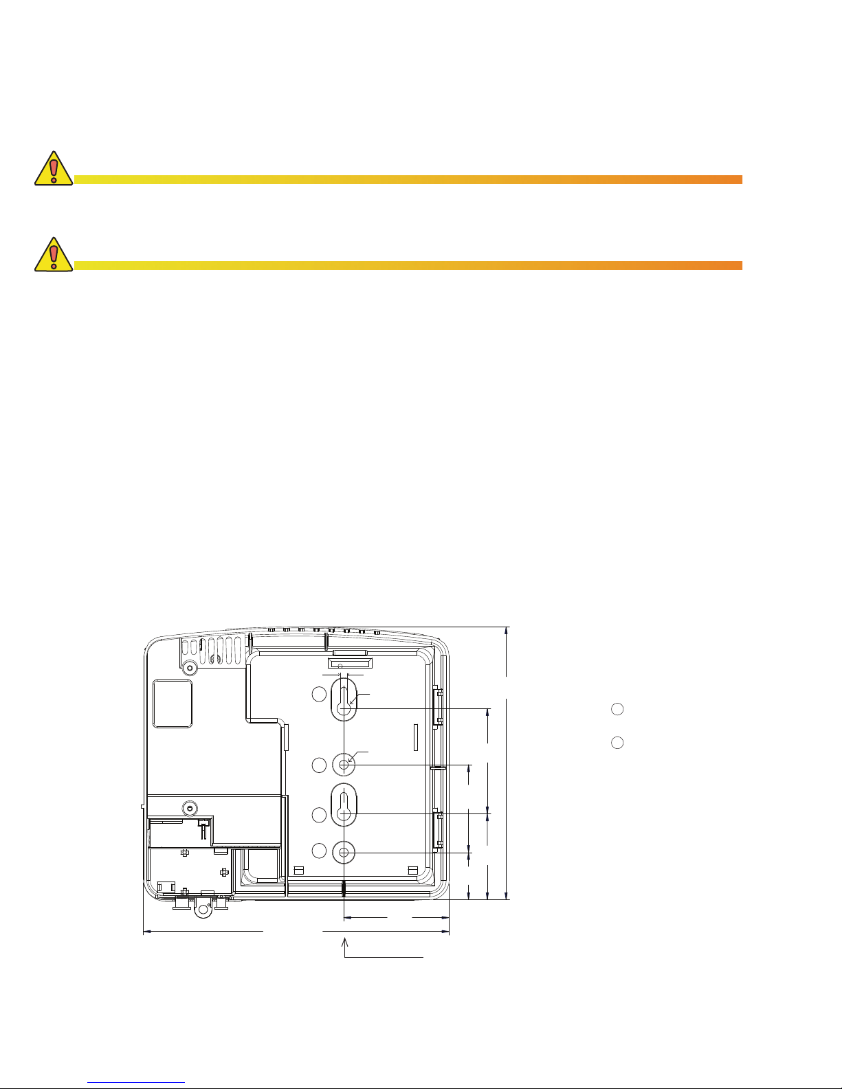
5. Mount the unit to the wall with #12 fasteners or equivalent, using the keyholes for easy
mounting. For applications (with 7.2Ah battery only) with higher seismic requirements,
use the round holes in the back of the unit for direct fastening to a stud or other structural
feature.
8.7"
221mm
.200"/5mm
2
1
2
1
0.380"
9.7mm
0.250"
6.35mm
3.0"
76mm
63.5mm
33mm
2.5"
1.3"
3.0"
76mm
2.4"
61mm
7.8"
198mm
Mounting holes for #12
1
hardware or equivalent
“Keyhole” slots for
2
easy mounting
Fig. 2-1, Unit Dimensions (in/mm), FPR1207-F as viewed from back
10
Center of Gravity
(with battery installed)
010-344-B1-001 Rev. A (2/2014)
Page 11
2.0 Installation, continued
2.1 Installation and Connection, continued
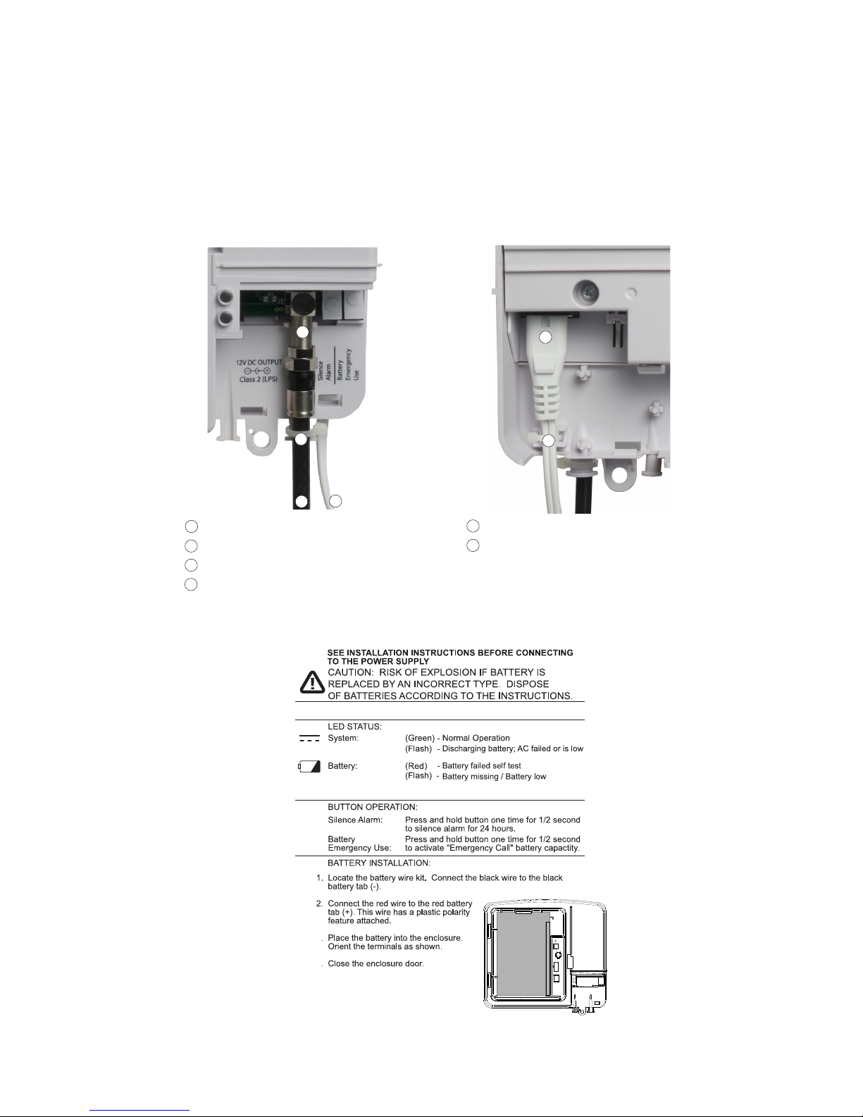
6. Connect Coax cable to F-type connector. Torque to between 4.1 in-lbs and 6.1 in-lbs. See
Figure 2-2.
Installation tip: Pre-bend the cable before connecting to the circuit board. This will prevent
stress on the circuit board caused by contact between the closed door of the unit and the
coax cable.
3
4
1
1
Output Coax Cable
2
AC Line Cord
3
12Vdc Output Connection
4
Cable tie
Fig. 2-2, FPR1207-F Output Cables and Connections
5
6
2
5
AC Input Connection
6
Cable tie
010-344-B1-001 Rev. A (2/2014)
3
4
Fig. 2-3, Function List (Inside Lid of Enclosure)
11
Page 12
2.0 Installation, continued
2.2 Battery Installation / Replacement Procedure
1. (Failed Battery Replacement) For units with Alpha part number 010-344-20-001 (note that
the nal three digits in bold are the key indicator), disconnect the AC line cord from the
AC power outlet before beginning battery replacement.
2. (Battery Replacement / Failed Battery Replacement) Disconnect the wire harness to the
battery.
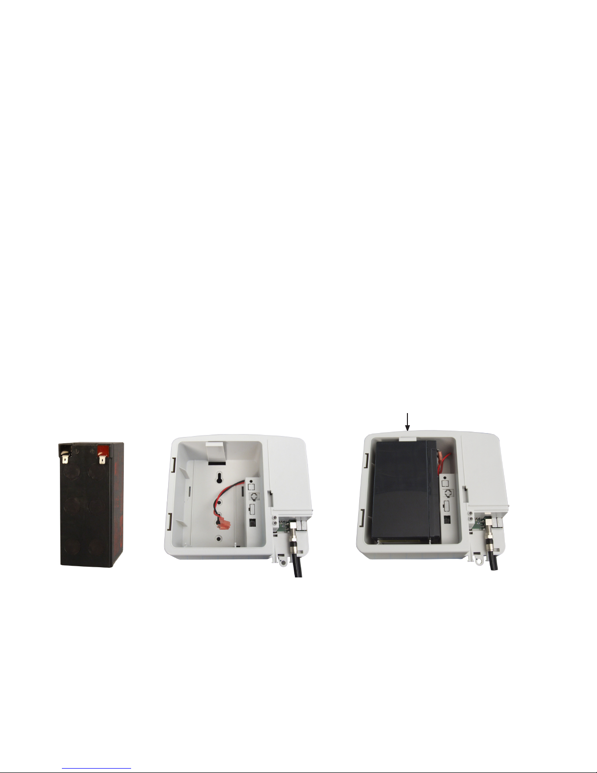
3. Connect the wire harness to the charged battery (a fully charged battery reads about
13Vdc).
4. Install the battery in the cradle as shown in Fig. 2-6. The locking tab secures it in place.
5. Replace the battery compartment door. To replace the front cover, align the hinges with
the hinge sockets and press them in with the door perpendicular with the main housing.
Rotate the door closed until the closure door latches.
6. Plug the FPR1207-F into an AC power outlet. The Green LED should light.
7. Verify the unit is functioning properly by unplugging the unit. The alarm should sound for
one second and the Green LED should ash. The unit will be running on standby battery
power.
Fig. 2-4, Battery
Terminals
8. Re-plug the FPR1207-F into an AC power outlet. The unit is ready to be placed into
service.
Locking tab
Fig. 2-5, Battery Compartment,
FPR1207-F
Fig. 2-6, Completed
Installation
12
010-344-B1-001 Rev. A (2/2014)
Page 13
3.0 Operation
R
Remove cover to access
silence alarm and battery
emergency use buttons.
3.1 Power On
1. Plug the unit into AC Power.
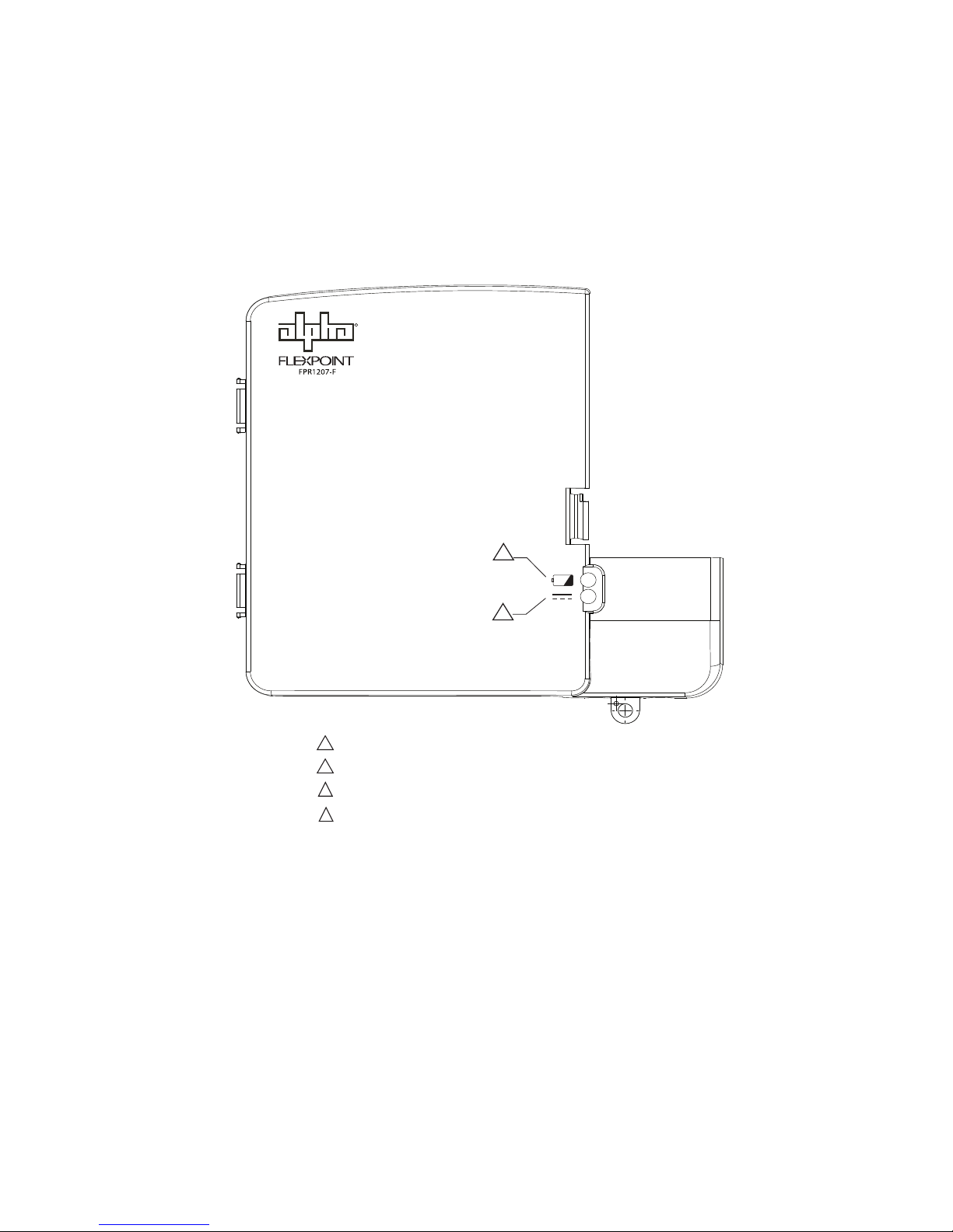
2. The green LED (2) should light. Additional LEDs on the front panel of the FPR1207-F
indicate the state of the system. Their functions are:
1
2
Red LED: Replace battery
1
1
Red LED ashing: Battery missing / Low battery
2
Green LED: AC mode
2
Green LED ashing: Battery mode
Fig. 3-1, Visual Status Indicators
3. Verify the unit is functioning properly by unplugging it. After approximately 10
seconds the alarm should briey sound.
4. Re-plug the unit into an AC power outlet. The battery status LED (1) will go out.
The unit is ready to be placed into service.
010-344-B1-001 Rev. A (2/2014)
13
Page 14
3.0 Operation, continued
3.2 Audible Alarms and Visual Indicators
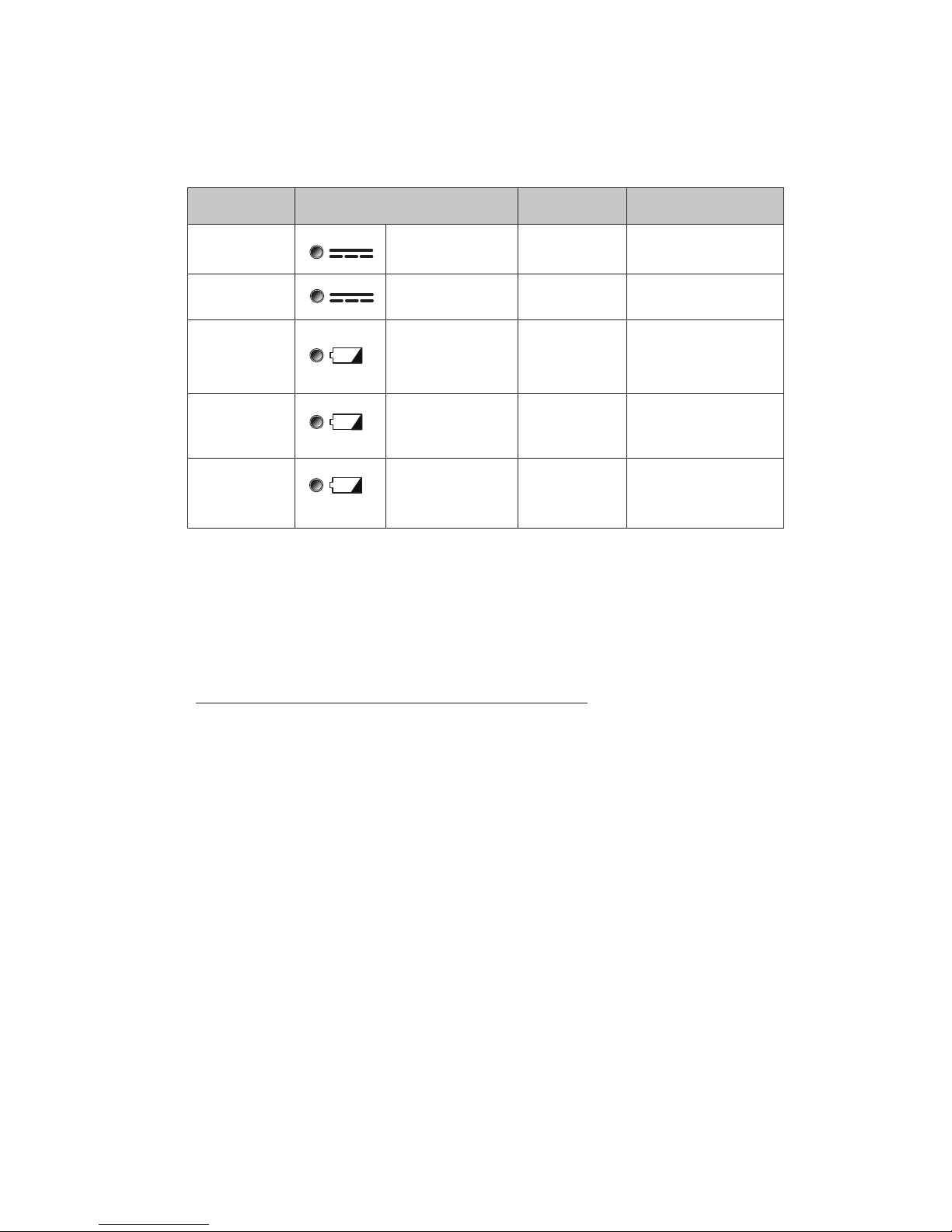
The table below details the audible alarms and visual indicators of the FPR1207-F.
Condition Status LED
NORMAL System LED (GREEN) N/A
ON BATTERY
LOW BATTERY RED LED blinking
REPLACE BATT RED LED steady
BATT MISSING RED LED blinking N/A
3.3 Battery
Battery construction varies signicantly between manufacturers. Alpha Technologies
recommends the use of qualied batteries only.
Part Description
AX-STDBAT-7 Battery 7.2Ah AGM, 1-year Warranty
AX-LONGBAT-7 Battery 7.2Ah AGM, 3-year Warranty
AX-LONGBAT-8 Battery, Longlife, 8Ah, AGM 3-year Warranty
Audible
Alarm
Battery LED (GREEN)
ash
(1) 1s beep on loss
of AC
When AC is available,
audible alarms are
suppressed. When AC
fails, 1 beep every 15s.
2 beeps, every 15
minutes
Table 3-1, Audible Alarms and Visual Indicators
Description
Condition normal; AC powers load,
charges battery.
Input fails; battery powers load.
When battery capacity is < 25%,
unit triggers alarm, or when the
“Battery Emergency Use” button
is pressed.
Every 180 days, the unit will
automatically initiate a battery
test. The test lasts approx. 60
min., and LED lights if battery
replacement is needed.
Approximately 20s after battery
removal, system initiates battery
detection routine. Battery detection
runs every 30s when oat
charging. Upon verication, alarm
tripped.
14
010-344-B1-001 Rev. A (2/2014)
Page 15

3.0 Operation, continued
3.4 Operational Modes
3.4.1 Normal Mode
This mode is dened as a state where the load is being supplied from AC input, and the
battery is oating, charging or in the process of being tested.
When the unit is initially powered-up, or whenever the input supply has been restored
after an outage, the unit operates in a charge mode. Once the battery voltage has
reached the full charge voltage, the unit switches to oat mode. If the input voltage is
less than the minimum AC input, the system switches to operating in back-up mode.
After approximately 180 days of operation, the battery is tested to determine whether it
has adequate capacity. It is tested when the following conditions are met:
1. The system is operating in oat mode
2. The battery is fully charged
If the battery is not fully charged, or the system is not operating in oat mode when the
test becomes due, the test is postponed until those conditions are met. If the AC input
is lost, or the unit is overloaded during the battery test, it will be aborted and indenitely
postponed until conditions are valid.
Once a battery test has been successfully executed, another test will be scheduled to
occur in 180 days.
3.4.2 Back-Up Mode
The load is being supplied from the battery while the battery voltage is greater than
11.5Vdc, which is approximately 25% state of charge. When the battery falls below this
point it is disconnected.
3.4.3 Emergency Use
Battery Emergency Use mode occurs after the back-up mode has nished, which the
user initiates by pressing “Battery Emergency Use” button. During this mode the battery
will be allowed to discharge until its voltage is 10.5Vdc, which is 0% state of charge. At
this time the system will shut down.
The operator should be aware of the following:
• Reserve time with 7W load at 25°C is approximately 30 minutes.
• Capacity reserved for emergency use is approximately 25%.
3.4.4 Charging Mode
Float charge maintains the battery at 100% capacity. If the battery is required to support
operation, charging ceases. When primary power is restored, battery charging resumes
and continues until one of the following occurs:
• Battery has reached 100% of capacity. Charging is reduced to oat charge level.
Normal charge current is approximately 350mA. When the current falls below
100 mA, the mode changes to oat. In the event the current does not reduce, the
software triggers the mode change.
• Another power failure occurs requiring battery support. Charging ceases until
primary power is restored.
• Additional power is required by the ONT. Power is diverted from the battery charger
and sent to the ONT. When demand for additional power ceases, normal battery
charging resumes.
• The battery is depleted. No special action is required to restore normal operation
once primary power is restored.
010-344-B1-001 Rev. A (2/2014)
15
Page 16

4.0 Specications
INPUT
AC Input Voltage 100 -240 (-15/+10%)
Input Frequency 50/60Hz
OUTPUT
Operational Output Power 7W max. continuous (ONT load*)
Output Voltage 12Vdc Nominal (Battery voltage upon loss of AC)
Connection F-type coaxial connector (Corning Gilbert RG6 or smaller)
BAT TERY
Bat ter y Typ e 7.2Ah AGM / 8Ah AGM
Recharge Time 18 hours to 90%
BAT TERY
Provides approximately 20 Hours of backup at 3.5W*
Provides approximately 12 Hours of backup at 7W*
*Base d on new, fully- charged battery
PHYSICAL
Housing Size (in/mm) 8.75W x 7.75H x 3.0D / 222W x 197H x 76D
Weight (lb/kg) 1.3 / 0.59
Battery 7.2Ah (lb/kg) 5.7 / 2.6
VI SUAL STATUS I ND ICATO RS
Green LED AC mode
Green LED Flashing Batter y mode
Red LED Replace battery
Red LED Flashing Battery missing/Low battery
AU DI BLE STATUS IN DICATORS
Loss of Input Power Single, one second beep
Low Batter y Single 0.5 second beep ever y 15 seconds at 25% SOC
Replace Battery Double beep every 15 minutes
PUSH BUTTONS
Silence Alarm Suppresses the audible alarm for 24 hours
Battery Emergency Use Accesses reserve battery capacity
AGENCY COMPLIANCE
Safety (US)
Safety (other)
Safety (EU) CE, EN 60950-1:2006, Evaluated for use with an IT power system
EMC (US) FCC part 15 subpart b, Class B
EMC (EU)
ENVIRONMENT
Storage Temperature -20°C to +50°C (-4°F to +122° F)
Operating Temperature 0°C to +40°C (32°F to +104°F)
Humidity 5 to 95%
Elevation Operation (max.) 0 to 10,000ft (0 to 3,048m) — derate 2°C per 1,000ft (305m) above 6,000ft (1830m)
Elevation Storage (max.) 50,000ft (15,240m)
Battery Storage
WARR ANTY
FlexPoint FPR1207-F 3 year, repair or replace
Battery Contact Alpha Technologies for model-specic warranty coverage
NRTL cer tied to UL/CSA 60950-1 Ed. 2 (ITE) (Pollution Degree 2, Overvoltage
Category II), LPS Output, SELV
IEC 60950-1:2005 + National Deviations. (Pollution Degree 2, Overvoltage Category
II), LPS Output, SELV
CE, EN 55022:2006 (CISPER 22) (Emissions) Class B, EN 55024:1998 +A1 +A2
(Immunity), EN 61000-3 -2:2006 (Harmonics), EN 61000-3-3 (Fluctuations and
Flicker) CE, RoHS compliant
-20°C to +40°C (-4°F to +104°F)
(six months max. storage duration at 25°C / 77°F without a recharge)
16
010-344-B1-001 Rev. A (2/2014)
Page 17

Page 18

Alpha Technologies Inc.
3767 Alpha Way
Bellingham, WA 98226
United States
Tel: +1 360 647 2360
Fax: +1 360 671 4936
Alpha Technologies Ltd.
7700 Riverfront Gate
Burnaby, BC V5J 5M4
Canada
Tel: +1 604 436 5900
Fax: +1 604 436 1233
Toll Free: +1 800 667 8743
Alpha Industrial Power Inc.
1075 Satellite Blvd NW,
Suite 400
Suwanee, GA 30024
United States
Tel: +1 678 475 3995
Fax: +1 678 584 9259
Alpha Energy
1628 W Williams Drive
Phoenix, AZ 85027
United States
Tel: +1 602 997 1007
Fax: +1 623 249 7833
Alpha Technologies Europe Ltd.
Twyford House Thorley
Bishop’s Stortford
Hertfordshire, CM22 7PA
United Kingdom
Tel: +44 1279 501110
Fax: +44 1279 659870
Alpha Technologies
Suite 1903, Tower 1
33 Canton Road, Kowloon
Hong Kong City, China
Phone: +852 2736 8663
Fax: +852 2199 7988
Alpha Technologies GmbH
Hansastrasse 8
D-91126
Schwabach, Germany
Tel: +49 9122 79889 0
Fax: +49 9122 79889 21
Alphatec Ltd.
339 St. Andrews St.
Suite 101 Andrea Chambers
P.O. Box 56468
3307 Limassol, Cyprus
Tel: +357 25 375 675
Fax: +357 25 359 595
Alpha Innovations Brasil
Avenida Ibirapuera,
2120 – Cj 76
Moema - 04028-001
Santos SP, Brazil
Tel: +55 11 2476 0150
Fax: +55 11 2476 0150
Technologies Argus
First de Mexico
Anatole France Num. 17
Colonia Polanco
11560, México D.F.
Tel: +52 55 5280 6990
Alpha TEK ooo
Khokhlovskiy Pereulok 16
Stroenie 1, Ofce 403
Moscow, 109028
Russia
Tel: +7 495 916 1854
Fax: +7 495 916 1349
Alphatec Baltic
S. Konarskio Street 49-201
Vilnius, LT-03123
Lithuania
Tel: +370 5 210 5291
Fax: +370 5 210 5292
Visit us at www.alpha.com
Due to continuing product development, Alpha Technologies reserves the right to change specications without notice.
Copyright © 2014 Alpha Technologies. All Rights Reserved. Alpha® is a registered trademark of Alpha Technologies. 010-344-B1-001 Rev. A (2/2014)
 Loading...