

Flexit UNI 3, UNI 4 User Manual
110737EN-13
2019-05
UNI 3
User Manual
Air Handling Unit & Automatic Control

UNI 3 User Manual
Contents
1 Functional Description Balanced Ventilation .................................................................4
1.1 Fans (M1, M2) ...............................................................................................................................................4
1.2 Filter (FI1, FI2) ..............................................................................................................................................4
1.3 Heat recovery system (HR-R) .................................................................................................................4
1.4 Heating element (EB1) (for UNI 3 E) ........................................................................................................4
1.5 Temperature sensors (B1, B4) .................................................................................................................. 4
2 Operation of Handheld Terminal .....................................................................................5
2.1 Horizontally Wall-Mounted Unit ..............................................................................................................5
2.3 Horizontal Unit ............................................................................................................................................6
2.4 For Necessary Removal of Door ..............................................................................................................6
3 Cleaning and Maintenance ..............................................................................................7
3.1 Fans................................................................................................................................................................7
3.2 Filter ...............................................................................................................................................................9
3.3 Replacing the brush strips ......................................................................................................................10
3.4 Rotor ............................................................................................................................................................11
3.5 Tightening of rotor belt ............................................................................................................................ 11
3.6 External Cleaning ......................................................................................................................................11
4 CI60 control unit overview ............................................................................................ 12
5 CI60 in use ...................................................................................................................... 13
5.1 General .........................................................................................................................................................13
5.2 Increasing/reducing air supply ...............................................................................................................13
5.3 Adjusting the air supply ............................................................................................................................13
5.4 Temperature adjustment .........................................................................................................................13
5.5 Filter replacement .....................................................................................................................................13
5.6 Alarm ............................................................................................................................................................13
6 CI600 control unit overview ......................................................................................... 14
5.7 Reset ...........................................................................................................................................................14
7 CI600 in use ................................................................................................................... 15
7.1 General ........................................................................................................................................................ 15
7.2 Idle mode ................................................................................................................................................... 15
7.3 Menu navigation ....................................................................................................................................... 15
7.4 Start menu ................................................................................................................................................. 15
7.5 Operating status ....................................................................................................................................... 15
8 CI600 main menu ...........................................................................................................16
8.1 Fan speeds.................................................................................................................................................. 16
8.2 Max. timer ................................................................................................................................................... 16
8.3 Settings ....................................................................................................................................................... 16
8.4 Temperature .............................................................................................................................................. 16
8.5 Timer............................................................................................................................................................ 17
8.6 Daily/weekly timer .................................................................................................................................... 17
8.7 Time and date ............................................................................................................................................ 18
8.8 Language .................................................................................................................................................... 18
8.9 Filter .............................................................................................................................................................18
8.10 Alarm ........................................................................................................................................................... 18
8.11 Operating information ............................................................................................................................. 18
9 CI600 advanced user menu ..........................................................................................19
9.1 PIN ............................................................................................................................................................... 19
9.2 Advanced user ........................................................................................................................................... 19
9.3 Temperature regulation .......................................................................................................................... 19
9.4 Fan control ................................................................................................................................................ 20
9.5 Configuration ............................................................................................................................................. 21
9.6 Operating time ......................................................................................................................................... 22
9.7 Service ....................................................................................................................................................... 22
9.8 Menu tree ...................................................................................................................................................23
10 Maintenance Table .........................................................................................................24
11 Troubleshooting .............................................................................................................24
12 CE Declaration of Conformity ........................................................................................25
Our products are subject to continuous development and we therefore reserve the right to make changes.
We also disclaim liability for any printing errors that may occur.
2
!
UNI 3 User Manual
!
Important Safety Instructions:
It is the installer’s responsibility to carry out a full safety and function assessment of the appliance.
To reduce the risk of fire, electric shock or injury, read all the safety instructions and warning texts before using the unit.
• This unit is only designed for ventilation air in housings or commercial buildings
• It must not be used to extract combustible or flammable gases
• Disconnect the mains plug before commencing any service and maintenance work
• Before opening the door: switch off the heat, let the fans continue for three minutes to remove hot air, disconnect power from
the unit and wait 2 minutes before opening the doors.
• If the supply cord is damaged, it must be replaced by the manufacturer, its service agent or a similarly qualified person, in
order to avoid hazard.
• The unit contains heating elements that must not be touched when they are hot
• The unit must not be operated without the filters in place
• Do not cook any combustible substances under the kitchen hood, if this is installed
• Do not leave a saucepan or frying pan containing oil or grease unsupervised when using a kitchen hood
• For the warranty to apply, the user manual instructions must be followed.
To maintain a good indoor climate, comply with regulations. To avoid condensation damage, the unit must never be
stopped apart from during service/maintenance or in connection with an accident.
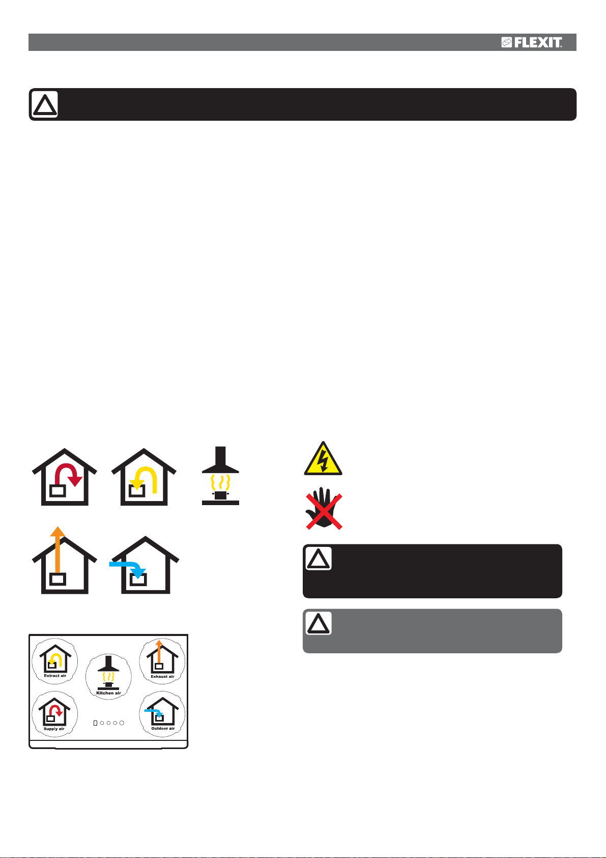
Symbols Used
These products bear a number of symbols used for
labelling the actual product and in installation and user
documentation.
Supply air
Exhaust air
Extract air Kitchen air
DANGER! ELECTRICITY
DANGER! DO NOT
TOUCH
CAUTION! When a text bears this symbol, it
means that personal injury or serious damage to
the equipment may result if the instructions are
not followed.
Outdoor air
NB! When a text bears this symbol, damage to
equipment or poor efficiency may be the consequence of not following the instructions.
EXAMPLE OF NIPPLE LOCATION
(shown as a right-hand model)
This appliance can be used by children aged from 8 years and above and
persons with reduced physical, sensory or mental capabilities or lack of
experience and knowledge if they have been given supervision or instruction
concerning use of the appliance in a safe way and understand the hazards
involved. Note that the product is not intended for use by children.
Children shall not play with the appliance. Cleaning and user maintenance
shall not be made by children without supervision.
Our products are subject to continuous development and we therefore
reserve the right to make changes.
We also disclaim liability for any printing errors that may occur.
3
UNI 3 User Manual
1 Functional Description Balanced
Ventilation
1.1 Fans (M1, M2)
The fans ensure that air enters and leaves the building. These
can be individually adjusted for optimal operation. The unit
can be regulated at 3 different speeds using the operating
panel; Min, Normal and Max. See section 5.1 for more
information.
1.2 Filter (FI1, FI2)
Filters with a high filter grade (ePM1 55% F7) are used as
standard both for supply air and extract air, so that the air
which enters the building is clean. The filters also ensure that
the unit stays clean.
1.3 Heat recovery system (HR-R)
The air goes through the rotary wheel heat recovery system.
The rotor functions as a heat storage. The heat from the
extract air heats up one half of the rotor. When the heated
part comes over to the supply air side, the heat is transferred
to the supply air.
Fig. 1
M2
B4
FI1
K
EB1
HR-R
M4
M1
B1
F20
F10
FI2
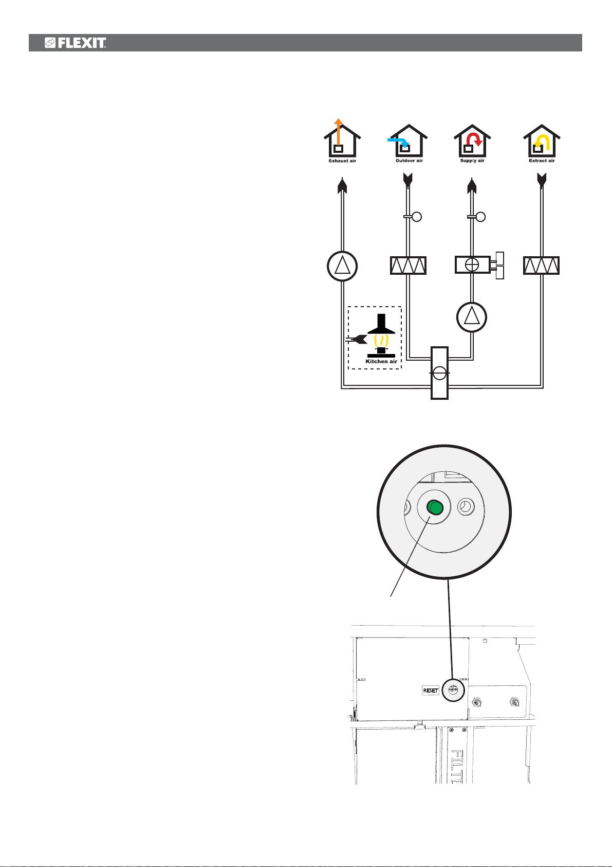
1.4 Heating element (EB1) (for UNI 3 E)
If the heat recovery system cannot raise the temperature
enough, an electrical heating element will raise the
temperature to a set level. The heating element is protected
against overheating by the thermostat (F20), which switches
off at 60°C. As an additional safety measure, the F10
thermostat switches off at 85°C. The F10 thermostat must be
reset manually by pressing the reset button (see Fig. 2).
1.5 Temperature sensors (B1, B4)
The unit has two temperature sensors as standard. Supply air
sensor B1 registers the temperature of the heating battery.
The outdoor air sensor (B4) registers the temperature of the
outdoor air.
Fig. 2
reset button
4
UNI 3 User Manual
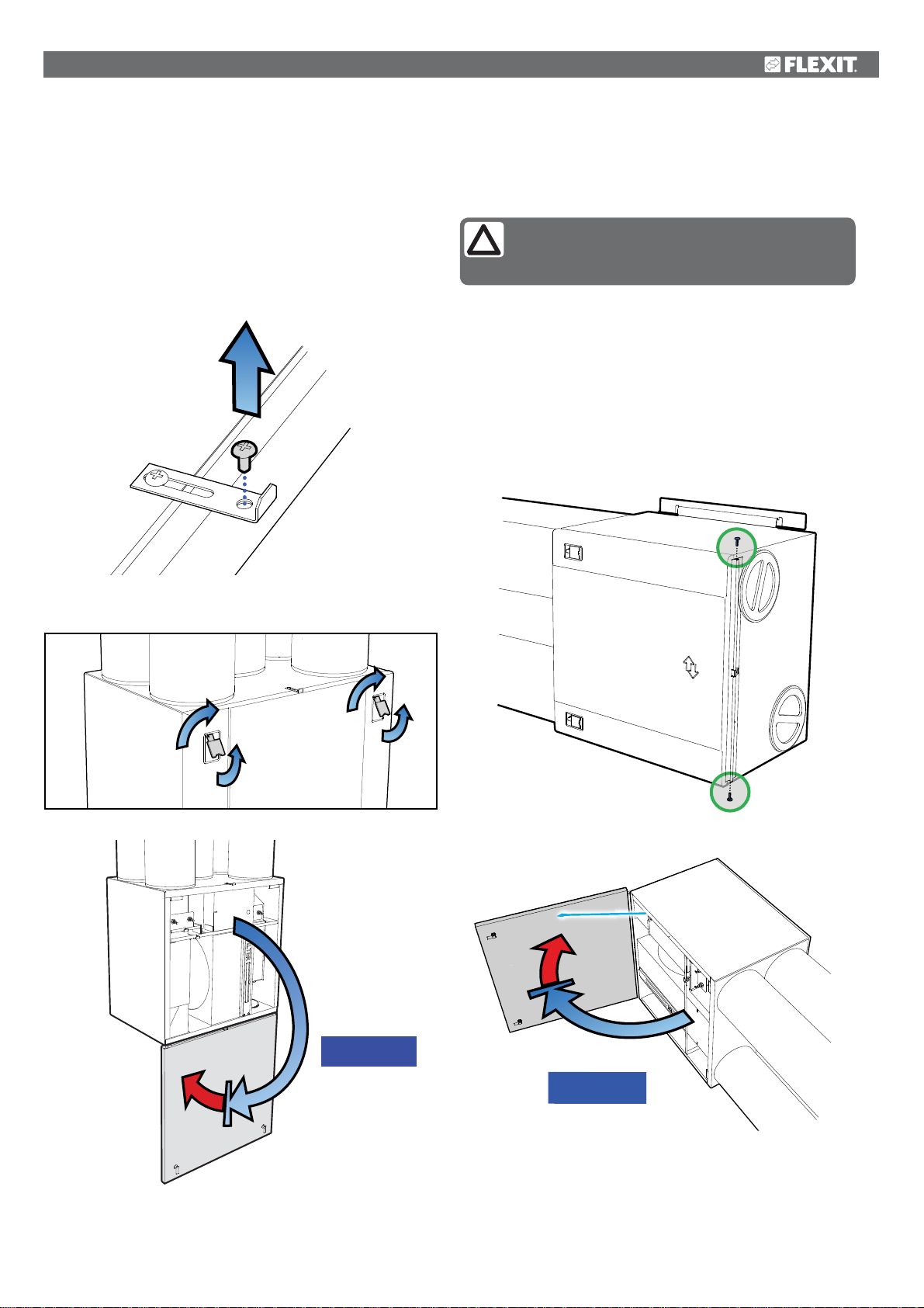
2 Operation of Handheld Terminal
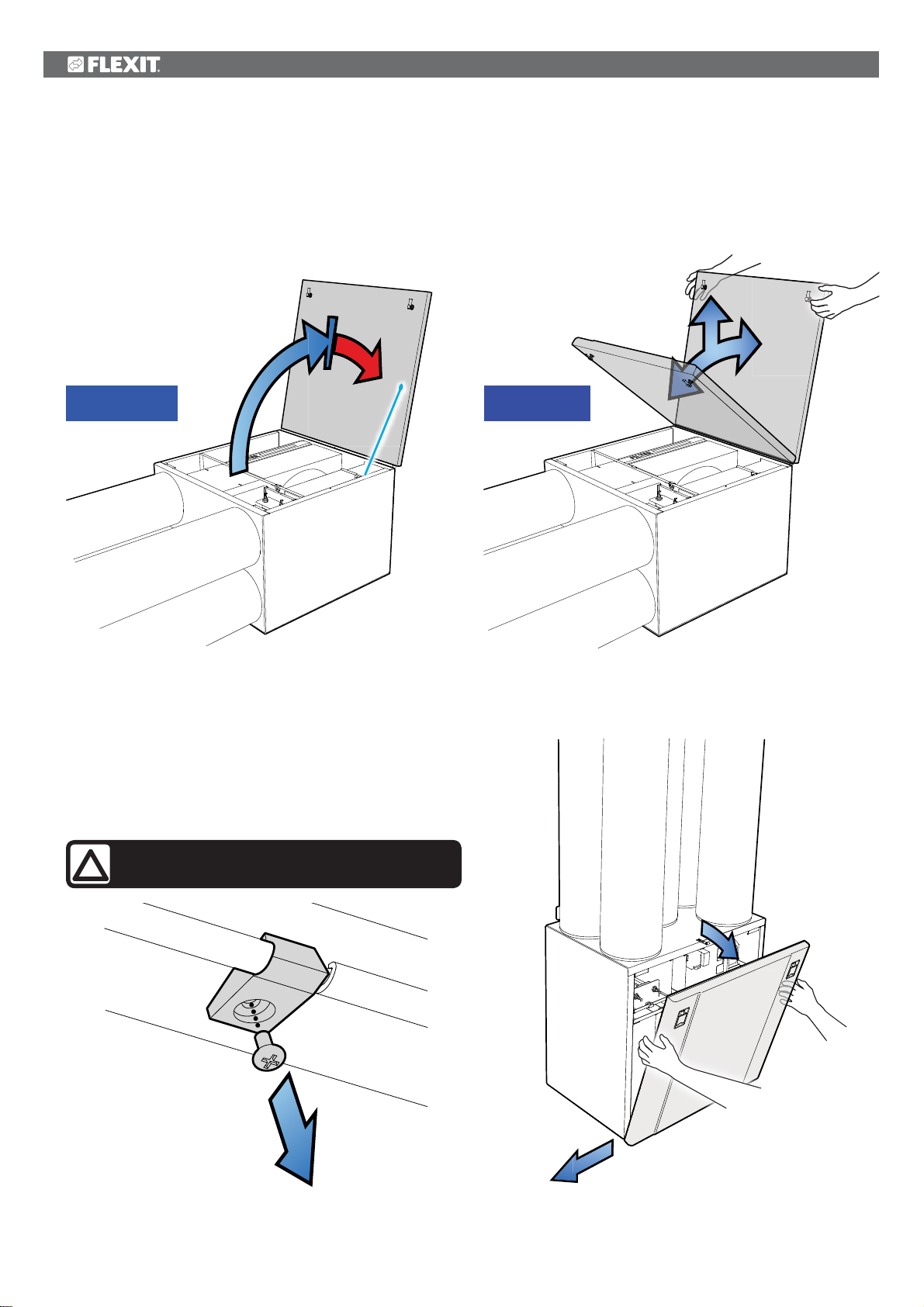
2.1 Horizontally Wall-Mounted Unit
1. 1he unit is opened by first unscrewing the screw in the top
(see Fig. 3).
2. Pull the handles out, and rotate to the side (see Fig. 4).
3. The door can now be opened to hang open at 180º (see
Fig. 5), or be hooked off (see point 2.4).
Fig. 3
Fig. 4
2.2 Sideways Wall-Mounted Unit
NB! A sideways mounted unit must have a strap
and end studs installed, so that the door does
not become damaged or fall off when opened.
1. Ensure that the end studs and strap are installed (Fig. 6
and Fig. 7).
2. Unscrew the top screw (see Fig. 3).
3. Pull the handles out, and rotate to the side (see Fig. 4).
4. The door can now be opened, but will have a maximum
swing of 105º (se Fig. 7).
Fig. 6
Fig. 5
Fig. 7
MAX 180°
MAX 105°
5
UNI 3 User Manual
!
40-105°
MAX 105°
2.3 Horizontal Unit
1. Ensure that the end studs and strap are installed (see Fig.
6 and 7).
2. Unscrew the top screw (see Fig. 3).
3. Pull the handles out, and rotate to the side (see Fig. 4).
4. The door can now be opened, but will have a maximum
swing of 105º (se Fig. 8).
Fig. 8 Fig. 9
MAX 105°
2.4 For Necessary Removal of Door
The door can be removed when it is open between 40º and
105º (see Fig. 9). If there is limited space in front of the unit,
the lock screw under the door can be temporarily unscrewed
(see Fig. 10), as well as the end studs if these are installed
(see Fig. 6). Then the door can be pushed out sideways (see
Fig. 11).
CAUTION! The door weighs 10kg, take care
when removing it.
40-105°
Fig. 10
Fig. 11
6
UNI 3 User Manual
!
3 Cleaning and Maintenance
CAUTION! Before opening the door: switch off
the heat, let the fans continue for three minutes
to remove hot air, disconnect power from the
unit and wait 2 minutes before opening the doors.
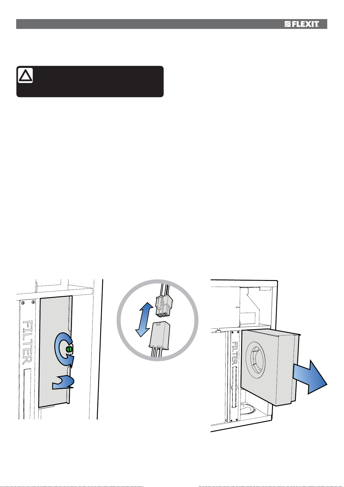
3.1 Fans
The fans must be cleaned a minimum of once a year. Clean
the fan blades with detergent (for example methylated spirit)
on a cloth and compressed air if possible. NB! Do not use
water.
To take out the fans:
1. Loosen the screw on the fan door (see Fig. 12).
2. Pull out the electric quick-release contact for the motor
(see Fig. 13).
3. The fan can then be carefully pulled out of the unit (see
Fig. 14).
4. Loosen the screws and remove the fan cover to access
the fan blades.
Fig. 12 Fig. 14Fig. 13
1
2
7
!
UNI 3 User Manual
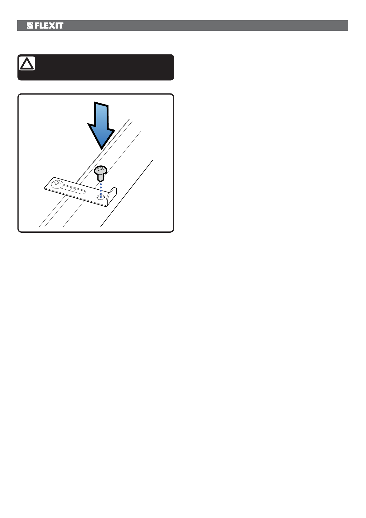
CAUTION! For safety reasons, always mount
the door screw when you’re finished
maintaining the ventilation unit!
8
UNI 3 User Manual
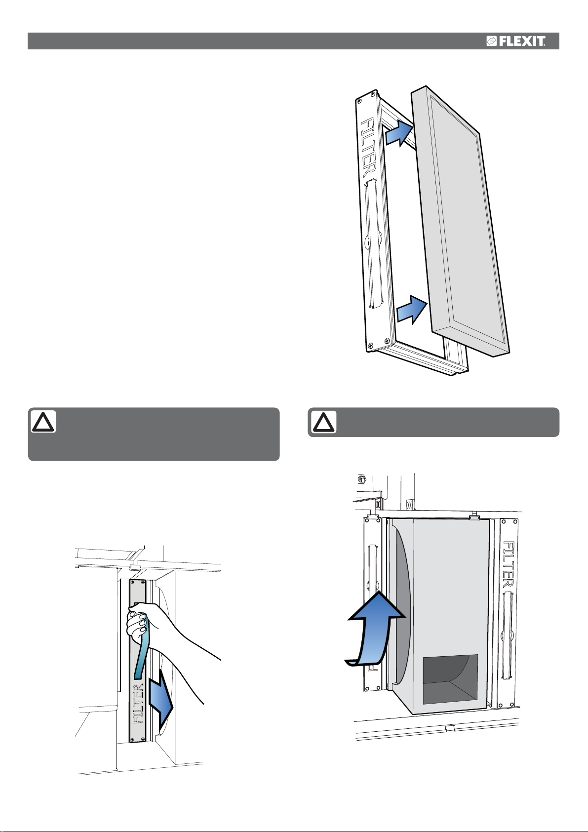
3.2 Filter
The filters have a limited lifetime, and to preserve a
healthy indoor air quality it is important to change them
when they are dirty.
How often the filters need to be changed depends on the
degree of contamination in the air where they are installed.
In general, the filters need to be changed a minimum of once
a year, preferably in the autumn (after the pollen season). In
areas with a lot of dust and contamination, the filters should
be changed in the spring and autumn.
Dirty filters can, among other things, lead to:
• Reduced performance of the unit
• The unit becoming dirty
• Humidity damage in the bathroom
• Reduced indoor air quality
A filter subscription is recommended to ensure full benefit
from the system. The article number for a replacement filter
set is 110716.
To take out the filters:
1. Grip the handle and pull the filter cassette out (see Fig.15).
2. Push the filter out of the cassette (see Fig.16).
3. Insert a new filter.
Fig. 16
NB! Ensure that the filter is not damaged during
installation. Use the filter’s outer edge when you
push it in. A damaged filter reduces the unit’s
effect and the air’s purity.
When changing the filter, check that the whole unit is working
normally. Use the following checklist:
• Check that the rotor is rotating (see Fig. 17).
• The unit has filters both for outdoor air and extract air.
• Check that the fans are clean.
Fig. 15
NB! When inserting the filter cartridge into its
slot, push it properly to prevent air leakage.
Fig. 17
9
 Loading...