

Flexit S3 R, SL4 R, S4 R/S7 R Operating Instructions Manual
FLEXIT S3 R
SL4 R
S4 R/S7 R
Operating Instructions
Air Handling Unit - Rotor
94273E-07
2011-01
gpd.sunwayinfo.com.cngpd.sunwayinfo.com.cn

2
Contents
1 Dimensioned Drawings/Measures 4
1.1 Dimensioned Drawing S3 R 4
1.2 Dimensioned Drawing SL4 R 4
1.3 Dimensioned Drawing S4 R/ S7 R 4
2 Mounting - Preparatory Work 5
2.1 Inspection/Maintenance 5
2.2 Required Space 5
2.3 Mounting requirements 5
2.4 Recommended sound isolation - Horizontal mounting 5
2.5 Recommended sound insulation - Wall mounting 5
3 Installing S3 R 6
3.1 Location 6
4 Installing SL4 R 7
4.1 Wall Mounting 7
4.2 Horizontal Mounting 8
5 Montering av S4 R/S7 R 9
5.1 Wall Mounting 9
5.2 Horizontal Mounting 9
6 Connections/ Electrical Connection 10
6.1 Automatics 10
6.2 Supply Air Temperature Sencor (B1) 10
6.3 Temperature sensor for water battery (B5) 10
6.4 External Components 10
7 Plumbing Works 11
7.1 Technical Spesifications Water Battery 11
7.2 Possible Valve Types 12
7.4 Possible Vent Motors 12
7.5 Placement of Duct Battery 12
7.6 Connections 12
8 General Pictures/System Drawings 13
8.1 S3 R 13
8.2 SL4 R 14
8.3 S4 R/S7 R 15
9 Capasity and sound data 16
9.1 Capacity Diagram, Sound Data, Specifications - S3 R 16
9.2 Capacity Diagram, Sound Data, Specifications - SL4 RE/SL4 RW 17
9.3 Capacity Diagram, Sound Data, Specifications - SL4 RE EC/SL4 RW EC 18
9.4 Capacity Diagram, Sound Data, Specifications - S4 RE/S4 RW 19
9.5 Capacity Diagram, Sound Data, Specifications - S4 RE EC/S4 RW EC 20
9.6 Capacity Diagram, Sound Data, Specifications - S7 RE/S7 RW 21
9.7 Capacity Diagram, Sound Data, Specifications - S7 RE/S7 RW EC 22
10 Installation of External Kitchen Hood 23
10.1 Technical Data 23
10.2 Installation of External Kitchen Hood 23
11 Adjusting the Kitchen Hood 24
11.1 Basic Ventilation 24
11.2 Forced Ventilation 24
11.3 Pressure Drop Measurement 24
12 Adjustment Curves External Kitchen Hood 25
12.1 Basic Ventilation S3 R/S3 RK 25
12.2 Forced Ventilation S3 R 25
12.3 Basic Ventilation SL4 R/SL4 R EC 26
12.4 Forced Ventilation SL4 R/SL4 R EC 26
13 Technical Spesifications 27
13.1 Technical Spesifictions S3 R 27
13.2 Technical Spesifictions SL4 R 27
13.3 Technical Data S4 R 28
13.4 Technical Data S7 R 28
14 Final Check 29
gpd.sunwayinfo.com.cngpd.sunwayinfo.com.cn
3
15 Important Safety Instructions 30
16 Functional Description 30
16.1 Heating Elements 30
16.2 Operation via Kitchen Hood (S3 R/SL4 R) 30
17 Cleaning - Maintenance, S3 R 31
18 Cleaning - Maintenance SL4 R 32
19 Cleaning - Maintenance S4 R/S7 R 33
20 Fault Location 34
21 CE Declaration of Conformity 35
22 Product/Environmental Declaration 36
!
CAUTION: When a text bears this symbol, it means that personal injury
or serious damage to the equipment may follow if the instructions are
not followed.
NB: When a text bears this symbol, damage to equipment or a poor utilisation ratio may be the consequence of not following the instructions.
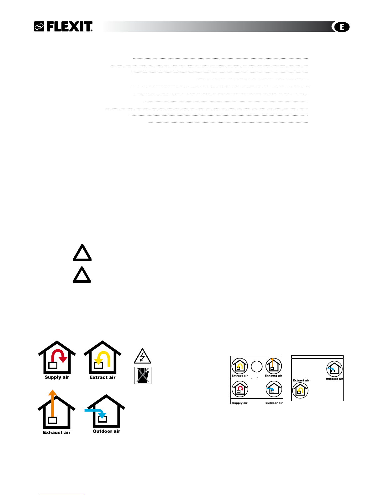
Symbols used
This product has a number of symbols that are used to label the product itself and in the installation and user documentation. Here is an explanation of some of the commonest symbols.
Our products are subject to continuous development and we therefore reserve the right to make changes.
We also disclaim liability for any printing errors that may occur.
EXTRACT AIR
OUTDOOR AIR
SUPPLY AIR
EXHAUST AIR
EXAMPLES OF DUCT LOCATIONS
DANGER! ELECTRICITY
DANGER! DO NOT TOUCH
TOP
BOTTOM
gpd.sunwayinfo.com.cngpd.sunwayinfo.com.cn
4
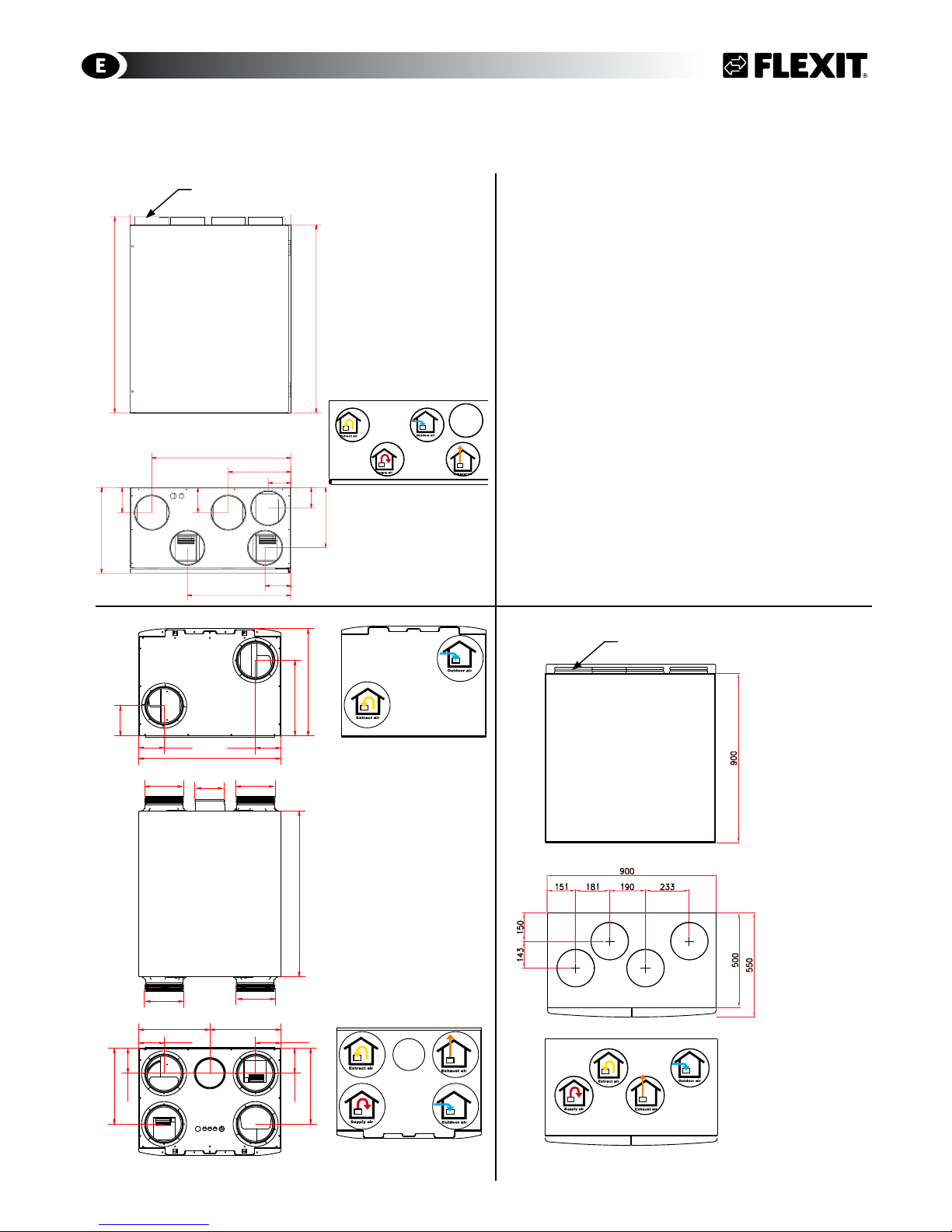
1 Dimensioned Drawings/Measures
1.1 Dimensioned Drawing S3 R
Kitchen hood
1.2 Dimensioned Drawing SL4 R
Unit bottom - Air stream direction
Unit top - Air stream direction
1
2
3
4
5
6
Date
Status
Description
Drawn
Approved
Projection
Scale
Replaces:
Replaced by:
07.02.2007
jan
7
0
0
,
0
600,0
320,0
7
3
0
,
0
84,0
232,0
517,0
95,0
385,0
8
2
,
0
2
3
0
,
0
9
8
,
5
9
8
,
0
3
2
0
,
0
1.3 Dimensioned Drawing S4 R/ S7 R
Right hand model
The left model is inverted
All measures in mm
All measures in mm
Right hand model
The left model is inverted
All measures in mm
Right hand model
The left model is inverted
S3 R
598
455
700
320
128
107
107
106
106
106
320
299299
320
106
Ø160 Ø160
Ø160
Ø160
Ø125
Kitchen Hood
Unit top - Air stream direction
Unit top - Air stream direction
Ø125 (5x) Muffemål
Ø200 (4x)
gpd.sunwayinfo.com.cngpd.sunwayinfo.com.cn
5
2 Mounting - Preparatory Work
Aggregatet er beregnet for innendørs
montering.
2.1 Inspection/Maintenance
The unit must be installed with space for service
and maintenance such as filter replacement and
cleaning the fans and recovery system. It is also
important for the unit to be located so that the
connectioncabinet is easily accessible for electrical
connection, troubleshooting and future component
replacement.
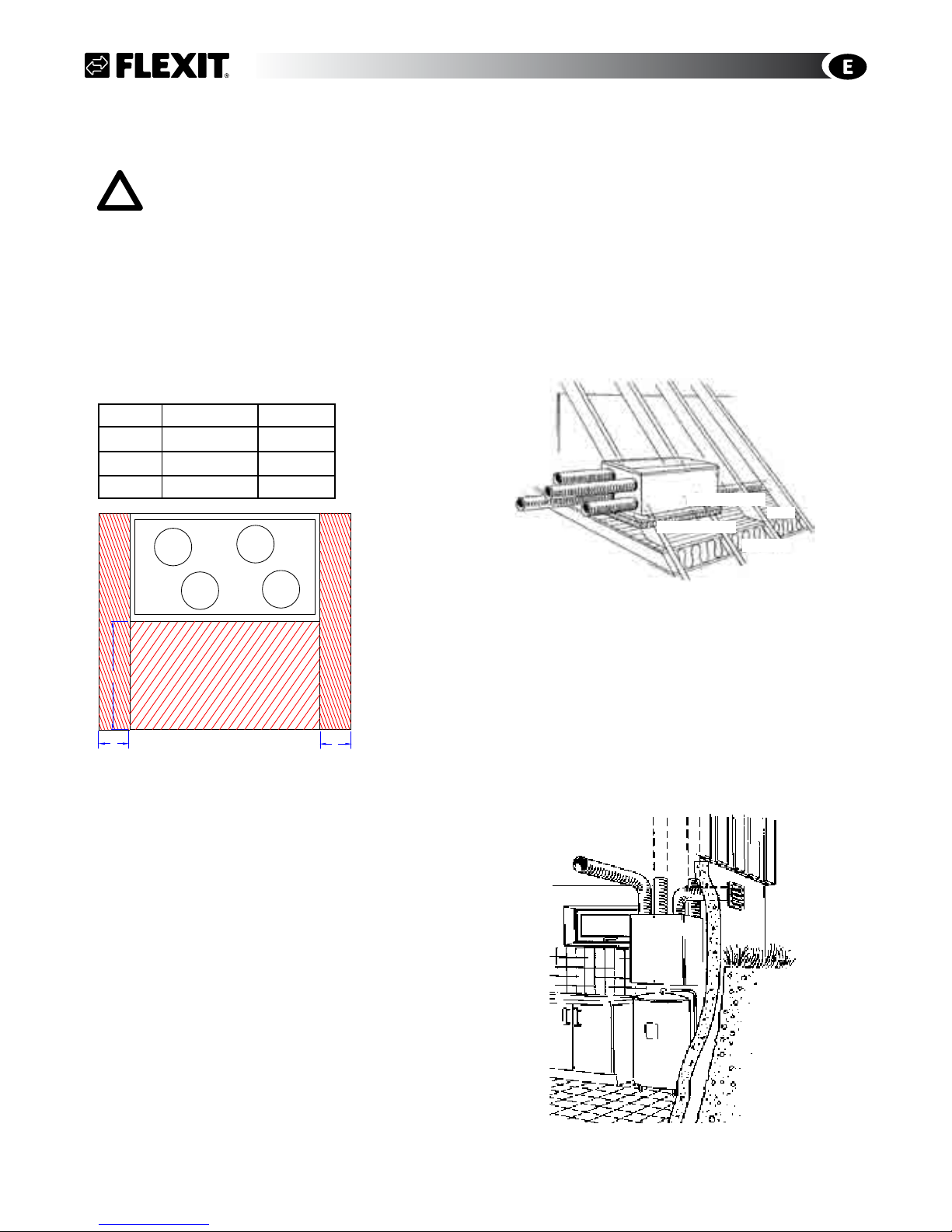
2.2 Required Space
Type A B
S3 R 1000 mm 0 mm
SL4 R 1000 mm 0 mm
S4/S7 R 1000 mm 60 mm
A: In front/over the unit
B: Distance to wall
These are minimum requirements that only take
service needs into account. National statutory
requirements for electrical safety may deviate from
this. Check which rules apply in your country.
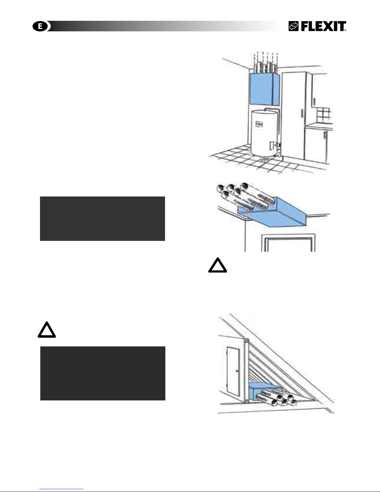
2.3 Mounting requirements
The unit is intended for use in washing rooms, baths,
attics or other suitable locations.
The unit is available in left and right versions
(exhaust air nipple to the left or right), depending
on what is the most favourable duct location. In wet
rooms the unit must be located in zone 3 (minimum
0.6 m from the edge of the bath and 1.2 m from the
shower head).
2.4 Recommended sound isolation - Horizontal
mounting
When mounted horizontally the unit should be on a firm
base, for example gypsum or chipboard, which must be
level.
If the room below is sensitive to noise, the panel can be
placed on a very firm panel of mineral wool for maximum
sound absorption (Fig. 2).
The unit should not be placed directly above a bedroom.
2.5 Recommended sound insulation -
Wall mounting
For wall mounting, the (included) wall bracket fixed to the
unit is used.
The unit must not be placed on a wall with rooms on the
other side which are sensitive to noise. The wall must be
sound-insulated. If necessary, use double plasterboards
on the wall.
Interrupted studs must be used.
Ekstra gulvplate
Ekstra isolasjon
Gulv
Isolasjon
Recommended surface
Fig. 2
Fig. 1
COMMON
B
B
A
gpd.sunwayinfo.com.cngpd.sunwayinfo.com.cn
6
3 Installing S3 R
3.1 Location
Mounting brackets and suspension have several
mounting holes to enable securing the unit to two
pillars. If this is not possible, consider using additional
studs (transoms).
Wall Mounted (3A)
The enclosed wall bracket is used for wall mounting
(Fig. 3B). (The wall must be sound insulated to prevent
sound penetration).
• The wall bracket (Fig. 3B) is screwed to the wall with
the enclosed screws.
• The unit is suspended from the rail.
• Fix the unit at the bottom with the enclosed
mounting bracket
The wall must be sound insulated to prevent noise
transfer. The unit shuld be palced against a wall which
does not have a sound sencitive adjoining room.
Ceiling Mounted (4A)
The enclosed ceiling brackets are used for ceiling
mounting (Fig. 6B).
• Attach the 4 small brackets to the unit in the
prefitted blind nuts with the 8 enclosed screws with
countersunk heads.
• Fit the suspension rails to the ceiling with the
enclosed screws.
• Lift the unit into place. The brackets on the unit
must lock into the ceiling-mounted rails.
The mounting hole furthest out (2 on each
side) must be fixed to joists or a concrete
ceiling. Use at least 8 screws
Fig. 3A
Fig. 6 A
Fig. 5
Fig. 4B
Horizontal mounting (Fig. 3) in the loft requires no
brackets. The unit should not be placed directly above
bedrooms on account of noise. Install it on a firm base
(gypsum/chipboard) that is level. Place the panel on
a very firm panel of mineral wool if additional sound
absorption is required (Fig2/Section. 2).
Fig. 3B
FOR CEILING-MOUNTED UNITS:
Be careful with the doors when opening the unit. They open suddenly when
the last screw is removed. Take care as
well when removing components. Hold
them when you remove the last screw
to avoid objects falling down. The rotor
requires extra care on account of its
weight.
!
Fig. 4A
S3 R
gpd.sunwayinfo.com.cngpd.sunwayinfo.com.cn
7
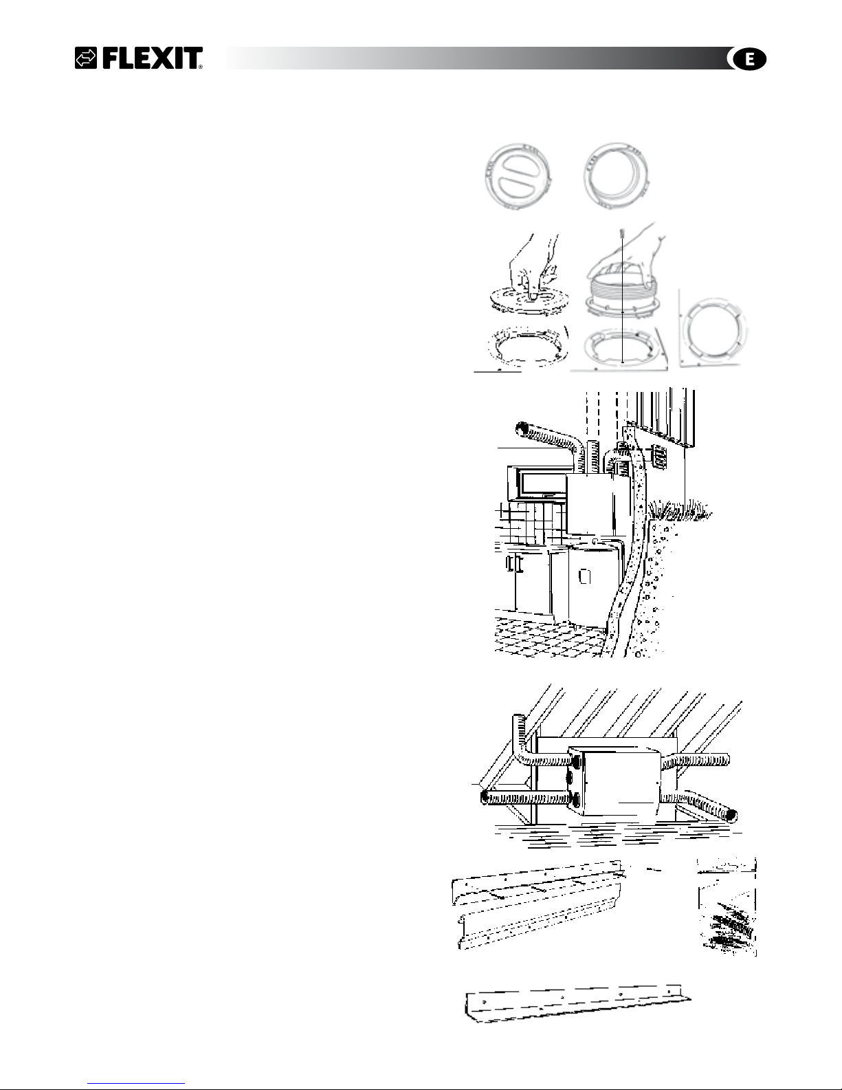
4 Installing SL4 R
The duct connections on the top and bottom of the unit
can be moved by turning the nipples/covers a quarter
turn and lifting them up (Fig. 8).
Fix the movable ducts at the top and bottom of the unit
(extract air and exhaust air) with self-tapping screws
from the installation kit. The location of the screws is
indicated on the ducts.
4.1 Wall Mounting
The enclosed wall bracket is used for wall mounting
(Fig. 8B/8C), which is fixed to the unit. Wall must be
sound insulated (Fig. 2/Chapt. 2).
The wall must be sound insulated to prevent noise
transfer. The unit should be placed against a wall which
does not have a sound sencitive adjoining room.
Duct connection top (Fig. 9)
• The wall bracket (Fig. 10B) is screwed to the wall with
the enclosed screws (Fig. 10D).
• The unit is suspended from the rail. As standard, the
unit has the mounting bracket mounted on the top
for 90o installation.
• Fix the unit at the bottom with the enclosed
mounting bracket (Fig. 10E).
Duct connection to the side (Fig. 10)
• For 180o/sideways installation, the mounting bracket
(Fig. 10C) must be unscrewed and installed on the
long side which faces up.
• The suspension rail (Fig. 10B) is screwed to the wall
with the enclosed screws (Fig. 10D).
• The unit is suspended from the rail.
• Fix the unit at the bottom with the enclosed
mounting bracket (Fig. 10E).
Fig. 9
Fig. 10A
Fig. 10B
Fig. 10D
Fig. 10C
Fig. 8
Fig. 10E
SL4 R
gpd.sunwayinfo.com.cngpd.sunwayinfo.com.cn
8
Fig. 11
Fig. 12
Fig. 13
Fig. 14
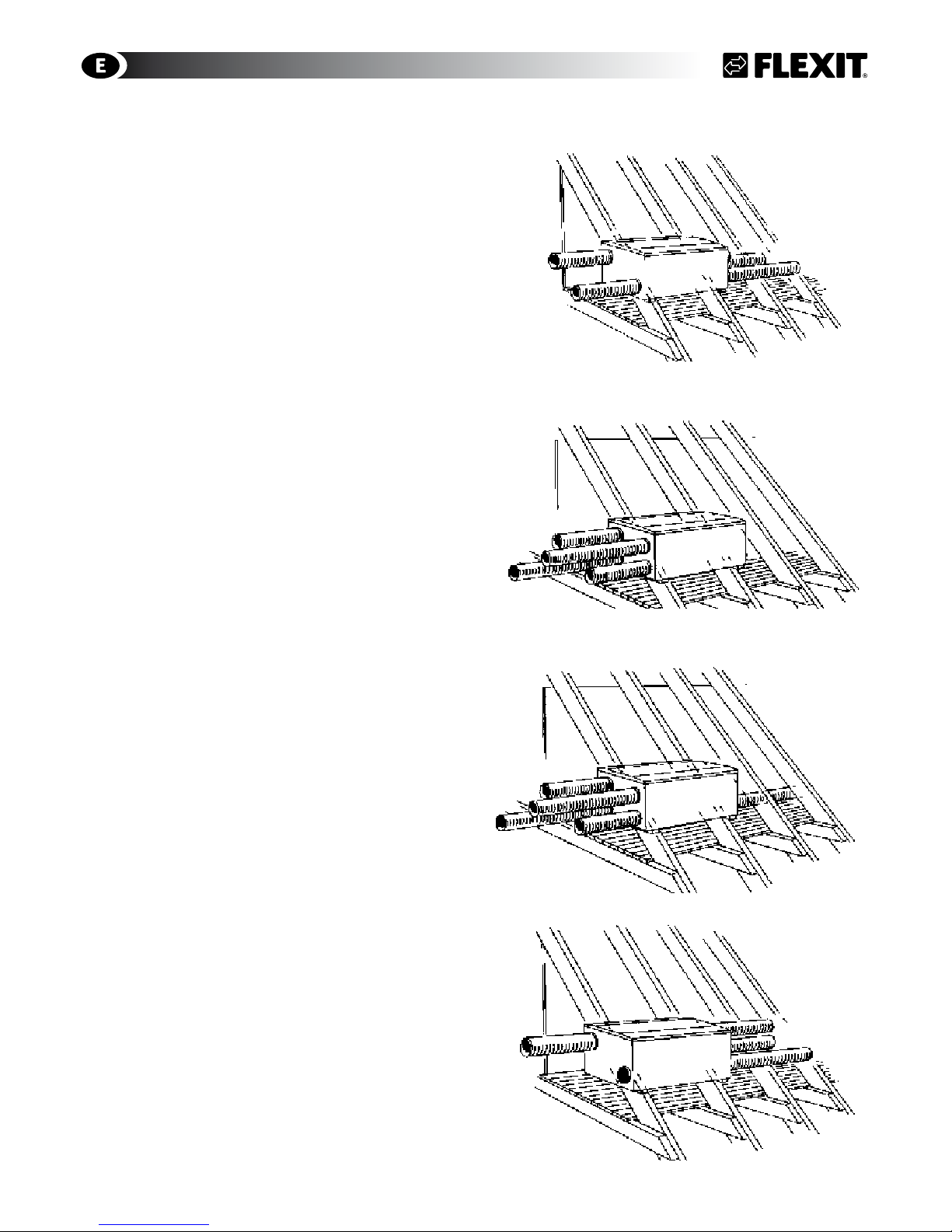
4.2 Horizontal Mounting
The ventilation unit should be installed on a firm base
(e.g. gypsum/chipboard) that is level.
If the room is noise sensitive, place the panel on a
very firm panel of mineral wool for additional sound
reduction (Fig. 2/Kap. 2). The unit should not be
installed above a bedroom. The figures 11-14 describe
the various duct connections available.
SL4 R
Right hand model
The left model is inverted
Right hand model
The left model is inverted
Left hand model
The right model is inverted
Left hand model
The right model is inverted
gpd.sunwayinfo.com.cngpd.sunwayinfo.com.cn
9
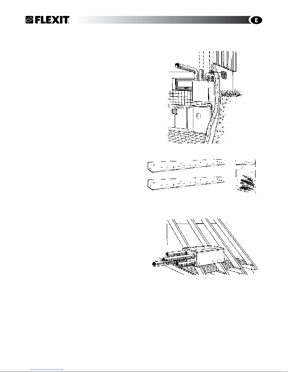
5 Mounting of S4 R/S7 R
These units are heavy and therfore it is necessary
to use additional studs (transcoms) between the
pillars on 48 x 98 mm, or 48 x 148 mm for suspension
above and support bracket below (c/c distance 900
mm) If using existing wall framework, mount an 18
mm plywood wallboard first to distribute the weight,
minimum the seize of the unit.
The wallboard must be secured to the framework in at
least 3 places with countersunk screws (6 attachment
screws 4.5 x 50 are included).
Mounting alternatives for the unit:
• Wall mounting (Fig. 15)
• Horizontal mounting (17)
5.1 Wall Mounting
The enclosed wall brackets are used for wall mounting
(Fig. 14A/14B). The wall must be sound insulated to
prevent noise transfer. The unit should be placed
against a wall which does not have a sound sencitive
adjoining room.
Duct connection top (Fig. 16)
• Attach one of the 2 mounting brackets (Fig. 16A) to
the ventilation unit with the enclosed screws (Fig.
16B).
• Lift the unit onto the wall and fasten with screws.
• Fix the unit at the bottom with the second enclosed
mounting bracket (Fig. 16A).
5.2 Horizontal Mounting
The ventilation unit should be installed on a firm base
(e.g. gypsum/chipboard) that is level.
If the room is noise sensitive, place the panel on a
very firm panel of mineral wool for additional sound
reduction (Fig. 2/Kap. 2). The unit should not be
installed above a bedroom.
Fig. 15
Fig. 16B
Fig. 16A
S4 R/S7 R
Fig. 17
gpd.sunwayinfo.com.cngpd.sunwayinfo.com.cn
10
COMMON
6 Connections of ducts and electrical
connection
• The ducts usually come from joists and are
connected to the nipples on the top of the unit.
• Ensure that the ducts are connected to the right
nipple. See the labelling on the unit (top/bottom
and behind door). The symbols are explained on
page 3 and the placing is shown on measurement
drawing in Chap. 1.
• Pull the duct insulation well up to the unit.
• To avoid condensation, it is very important for the
outdoor air duct to have insulation and a plastic
sleeve pulled right down to the unit. Seal the plastic sleeve to the unit with tape.
The outdoor air duct is normally designed with 25
mm insulation.
• Lay the outdoor air duct with a slight incline towards the outdoor air cap so that any water that
enters drains out again.
• With a short distance between the unit and the
exhaust point, sound insulation must be installed
to meet the requirements for the outdoor sound
level.
• Ducts must have good sound insulation, particularly above the unit.
• All electrical connections must be made by qualified personell only.
The unit must be equipped with a separate
earth-leakage circuit-breaker.
Power Cord
The unit is supplied with a 1.8 m cable and plug (which
also functions as the service switch). The cable emerges on the top of the unit (front) on the left side of a right
model and the right side of a left model. This is connected to a 230 V 50 Hz single-phase earthed power
point that is located in an easily accessible position
close by. For fuse types, see chapt. 14.
6.1 Automatics
The control package is supplied with the unit. The lowvoltage cable must be laid between the unit and the
switch unit. See separate automatics documentation.
The low-voltage cable must be laid at least
30 cm away from the 230 V cable. For flush installation, lay the cable in 20 mm conduit pipe.
6.2 Supply Air Temperature Sencor (B1)
Temperature sensor B1 must be placed after
the water battery.
This should be placed in the supply air duct (red on Flexit
Drawing/
Symbold Used
page 3) approx. 1 m from the unit.
Roll out the marked wire coil on the unit located close to
the supply air intake. Drill a Ø 7 mm hole in the duct where
the sencor can be placed. Seal the hole with a sealant and
tape the wire on the outside of the duct to keep in place.
6.3 Temperature sensor for water battery (B5)
In order to avoid that the water battery is destroyed by
frost a temperature sensor (B5) must be installed on the
return water pipe where the cold water leaves the battery.
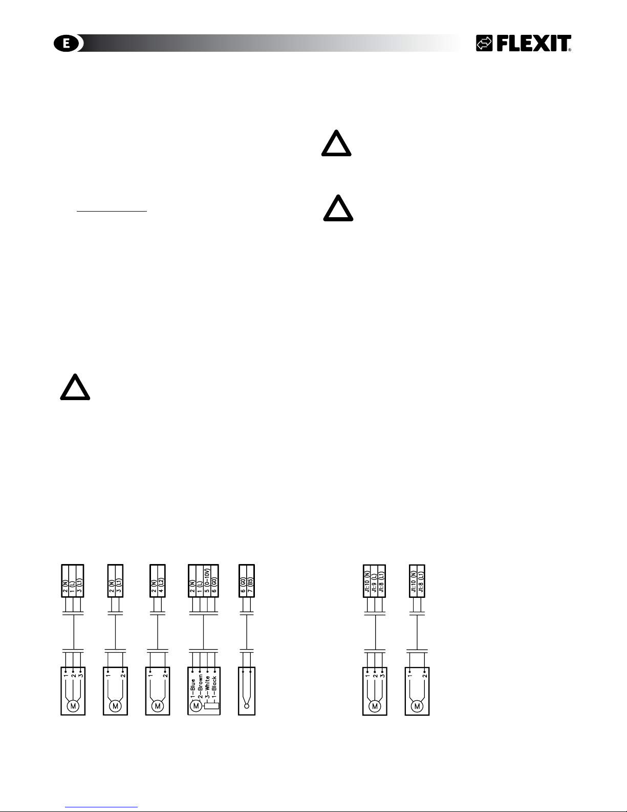
6.4 External Components
Refer to separate electrical circut drawing enclosed
with the individual ventilation unit and Fig. 18 below.
Water models Electrical models
Connected to external box Connected directely on the mainvboard
Damper motor 230V
3-wires
Damper motor 230V
2-wires
Pump motor 230V
Vent motor 230V
3-way vent
B5 Temperature sensor
Water battery
Damper motor 230V
3-wires
Damper motor 230V
2-wires
Fig. 18
gpd.sunwayinfo.com.cngpd.sunwayinfo.com.cn
11
WATER BATTERY
7 Plumbing Works
All plumbing must be performed by a qualified plumber.
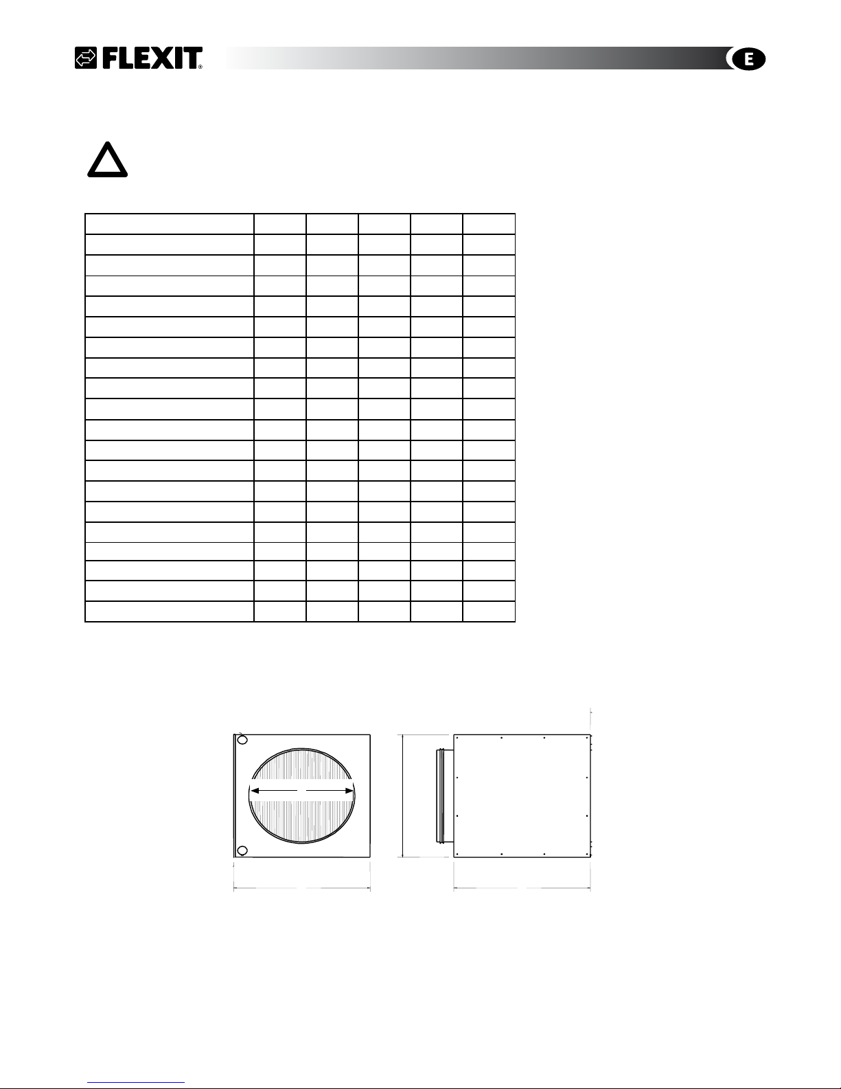
7.1 Technical Spesifications Water Battery
Water temp. In °C 80 70 60 50 40
Water temp. Out °C 60 50 40 30 30
S4R/SL4R
Water pressure l/s 0,03 0,03 0,02 0,02 0,02
Pressure drop waterside kPa 2,99 1,98 1,1 1,24 1,8
Max battery capasity kW 2,86 2,23 1,56 1,25 1
Max temp. increase °C 23,4 18,2 12,8 10,2 8,2
Pipe connection Ø mm 10 10 10 10 10
Recommended kvs-value 1,0 1,0 1,0 1,0 1,0
S7R
Water pressure l/s 0,08 0,06 0,05 0,03 0,06
Pressure drop waterside kPa 17,85 12,58 8,04 4,25 12,97
Max battery capasity kW 6,19 5,01 3,82 2,6 2,42
Max temp. increase °C 29,5 23,9 18,25 12,4 11,5
Pipe connection Ø mm 1/2” 1/2” 1/2” 1/2” 1/2”
Recommended kvs-value 1,6 1,6 1,6 1,0 1,0
PHYSICAL DIMENSIONS
A B C D
S4R/SL4R mm 205 205 350 160
S7R mm 351 255 350 200
Fig. 20 Duct battery
D
B
C
A
gpd.sunwayinfo.com.cngpd.sunwayinfo.com.cn
12
7.2 Possible Valve Types
3-way valve, type Belimo DN15:
Article no. 56597 Kvs 1,6
Article no. 56604 Kvs. 1,0
7.3 Possible Vent Motors
Vent motor type Belimo L230A-SR, 0-10V.
Article no. 56596.
24V motor can not be used
7.4 Placement of Duct Battery
The duct battery must be placed horizontally (Fig. 20/
Chapter 8.1). When placed in an non-insulated room
the battery itself must be insulated.
S4 R/SL4 R 14466
S7 R 14467
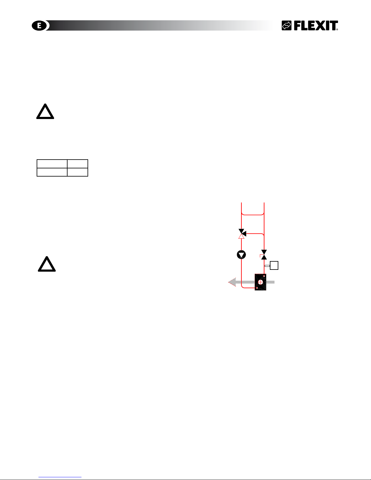
7.5 Connections
Use the recommended connection (see Fig. 20) unless
specified otherwise. The water supply must be at the
bottom of the water battery - the return must be on
the top.
Place the adjustment valve as close to the unit as
possible. (Please note that many valve motors can go
in both directions and this can be set on the motor.
Set it so that the valve opens on an increasing 0-10 V
signal.)
Before connecting the water battery, it
is necessary to check that the inspection
doors are accessible and there is space
enough to change the water battery.
If you use a water battery that has not had glycol
(or another antifreeze) added, the unit should be in
a heated room on account of the risk of frost in the
battery. Install air dampers with spring-loaded return
for outdoor air. Place the unit close to a gully to avoid
damage caused by any water leaks.
Fig. 21 Recommended connection
Pump
Throttle valve
3-way valve
Hot water from
boiler system
Water battery in the
supply air system
WATER BATTERY
B5
gpd.sunwayinfo.com.cngpd.sunwayinfo.com.cn
 Loading...