

FLEXIT S3 R
SL4 R
S4 R/S7 R
Operating Instructions
Air Handling Unit - Rotor
94273E-07
2011-01
gpd.sunwayinfo.com.cngpd.sunwayinfo.com.cn

2
Contents
1 Dimensioned Drawings/Measures 4
1.1 Dimensioned Drawing S3 R 4
1.2 Dimensioned Drawing SL4 R 4
1.3 Dimensioned Drawing S4 R/ S7 R 4
2 Mounting - Preparatory Work 5
2.1 Inspection/Maintenance 5
2.2 Required Space 5
2.3 Mounting requirements 5
2.4 Recommended sound isolation - Horizontal mounting 5
2.5 Recommended sound insulation - Wall mounting 5
3 Installing S3 R 6
3.1 Location 6
4 Installing SL4 R 7
4.1 Wall Mounting 7
4.2 Horizontal Mounting 8
5 Montering av S4 R/S7 R 9
5.1 Wall Mounting 9
5.2 Horizontal Mounting 9
6 Connections/ Electrical Connection 10
6.1 Automatics 10
6.2 Supply Air Temperature Sencor (B1) 10
6.3 Temperature sensor for water battery (B5) 10
6.4 External Components 10
7 Plumbing Works 11
7.1 Technical Spesifications Water Battery 11
7.2 Possible Valve Types 12
7.4 Possible Vent Motors 12
7.5 Placement of Duct Battery 12
7.6 Connections 12
8 General Pictures/System Drawings 13
8.1 S3 R 13
8.2 SL4 R 14
8.3 S4 R/S7 R 15
9 Capasity and sound data 16
9.1 Capacity Diagram, Sound Data, Specifications - S3 R 16
9.2 Capacity Diagram, Sound Data, Specifications - SL4 RE/SL4 RW 17
9.3 Capacity Diagram, Sound Data, Specifications - SL4 RE EC/SL4 RW EC 18
9.4 Capacity Diagram, Sound Data, Specifications - S4 RE/S4 RW 19
9.5 Capacity Diagram, Sound Data, Specifications - S4 RE EC/S4 RW EC 20
9.6 Capacity Diagram, Sound Data, Specifications - S7 RE/S7 RW 21
9.7 Capacity Diagram, Sound Data, Specifications - S7 RE/S7 RW EC 22
10 Installation of External Kitchen Hood 23
10.1 Technical Data 23
10.2 Installation of External Kitchen Hood 23
11 Adjusting the Kitchen Hood 24
11.1 Basic Ventilation 24
11.2 Forced Ventilation 24
11.3 Pressure Drop Measurement 24
12 Adjustment Curves External Kitchen Hood 25
12.1 Basic Ventilation S3 R/S3 RK 25
12.2 Forced Ventilation S3 R 25
12.3 Basic Ventilation SL4 R/SL4 R EC 26
12.4 Forced Ventilation SL4 R/SL4 R EC 26
13 Technical Spesifications 27
13.1 Technical Spesifictions S3 R 27
13.2 Technical Spesifictions SL4 R 27
13.3 Technical Data S4 R 28
13.4 Technical Data S7 R 28
14 Final Check 29
gpd.sunwayinfo.com.cngpd.sunwayinfo.com.cn
3
15 Important Safety Instructions 30
16 Functional Description 30
16.1 Heating Elements 30
16.2 Operation via Kitchen Hood (S3 R/SL4 R) 30
17 Cleaning - Maintenance, S3 R 31
18 Cleaning - Maintenance SL4 R 32
19 Cleaning - Maintenance S4 R/S7 R 33
20 Fault Location 34
21 CE Declaration of Conformity 35
22 Product/Environmental Declaration 36
!
CAUTION: When a text bears this symbol, it means that personal injury
or serious damage to the equipment may follow if the instructions are
not followed.
NB: When a text bears this symbol, damage to equipment or a poor utilisation ratio may be the consequence of not following the instructions.
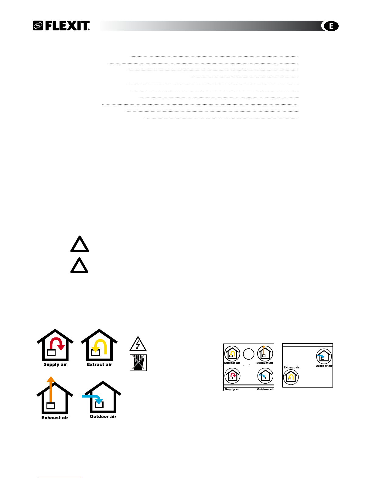
Symbols used
This product has a number of symbols that are used to label the product itself and in the installation and user documentation. Here is an explanation of some of the commonest symbols.
Our products are subject to continuous development and we therefore reserve the right to make changes.
We also disclaim liability for any printing errors that may occur.
EXTRACT AIR
OUTDOOR AIR
SUPPLY AIR
EXHAUST AIR
EXAMPLES OF DUCT LOCATIONS
DANGER! ELECTRICITY
DANGER! DO NOT TOUCH
TOP
BOTTOM
gpd.sunwayinfo.com.cngpd.sunwayinfo.com.cn
4
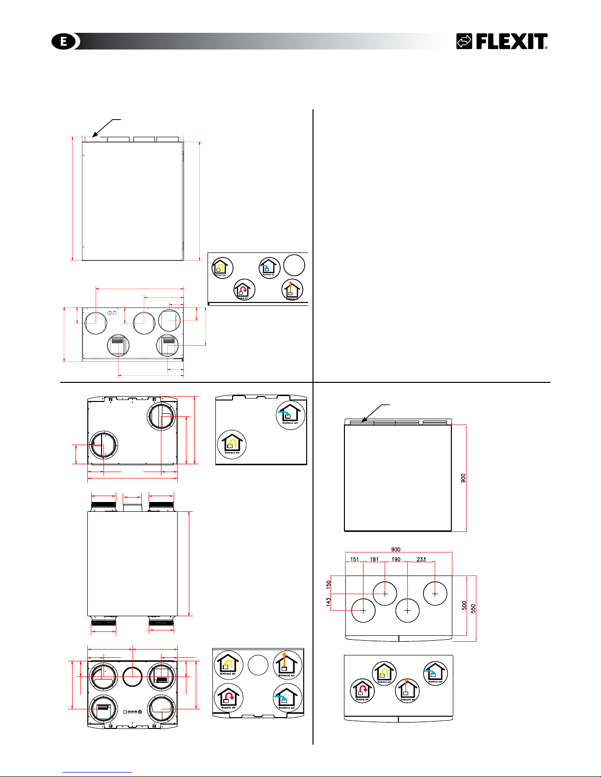
1 Dimensioned Drawings/Measures
1.1 Dimensioned Drawing S3 R
Kitchen hood
1.2 Dimensioned Drawing SL4 R
Unit bottom - Air stream direction
Unit top - Air stream direction
1
2
3
4
5
6
Date
Status
Description
Drawn
Approved
Projection
Scale
Replaces:
Replaced by:
07.02.2007
jan
7
0
0
,
0
600,0
320,0
7
3
0
,
0
84,0
232,0
517,0
95,0
385,0
8
2
,
0
2
3
0
,
0
9
8
,
5
9
8
,
0
3
2
0
,
0
1.3 Dimensioned Drawing S4 R/ S7 R
Right hand model
The left model is inverted
All measures in mm
All measures in mm
Right hand model
The left model is inverted
All measures in mm
Right hand model
The left model is inverted
S3 R
598
455
700
320
128
107
107
106
106
106
320
299299
320
106
Ø160 Ø160
Ø160
Ø160
Ø125
Kitchen Hood
Unit top - Air stream direction
Unit top - Air stream direction
Ø125 (5x) Muffemål
Ø200 (4x)
gpd.sunwayinfo.com.cngpd.sunwayinfo.com.cn
5
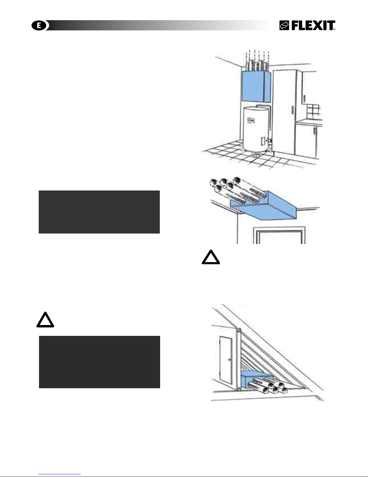
2 Mounting - Preparatory Work
Aggregatet er beregnet for innendørs
montering.
2.1 Inspection/Maintenance
The unit must be installed with space for service
and maintenance such as filter replacement and
cleaning the fans and recovery system. It is also
important for the unit to be located so that the
connectioncabinet is easily accessible for electrical
connection, troubleshooting and future component
replacement.
2.2 Required Space
Type A B
S3 R 1000 mm 0 mm
SL4 R 1000 mm 0 mm
S4/S7 R 1000 mm 60 mm
A: In front/over the unit
B: Distance to wall
These are minimum requirements that only take
service needs into account. National statutory
requirements for electrical safety may deviate from
this. Check which rules apply in your country.
2.3 Mounting requirements
The unit is intended for use in washing rooms, baths,
attics or other suitable locations.
The unit is available in left and right versions
(exhaust air nipple to the left or right), depending
on what is the most favourable duct location. In wet
rooms the unit must be located in zone 3 (minimum
0.6 m from the edge of the bath and 1.2 m from the
shower head).
2.4 Recommended sound isolation - Horizontal
mounting
When mounted horizontally the unit should be on a firm
base, for example gypsum or chipboard, which must be
level.
If the room below is sensitive to noise, the panel can be
placed on a very firm panel of mineral wool for maximum
sound absorption (Fig. 2).
The unit should not be placed directly above a bedroom.
2.5 Recommended sound insulation -
Wall mounting
For wall mounting, the (included) wall bracket fixed to the
unit is used.
The unit must not be placed on a wall with rooms on the
other side which are sensitive to noise. The wall must be
sound-insulated. If necessary, use double plasterboards
on the wall.
Interrupted studs must be used.
Ekstra gulvplate
Ekstra isolasjon
Gulv
Isolasjon
Recommended surface
Fig. 2
Fig. 1
COMMON
B
B
A
gpd.sunwayinfo.com.cngpd.sunwayinfo.com.cn
6
3 Installing S3 R
3.1 Location
Mounting brackets and suspension have several
mounting holes to enable securing the unit to two
pillars. If this is not possible, consider using additional
studs (transoms).
Wall Mounted (3A)
The enclosed wall bracket is used for wall mounting
(Fig. 3B). (The wall must be sound insulated to prevent
sound penetration).
• The wall bracket (Fig. 3B) is screwed to the wall with
the enclosed screws.
• The unit is suspended from the rail.
• Fix the unit at the bottom with the enclosed
mounting bracket
The wall must be sound insulated to prevent noise
transfer. The unit shuld be palced against a wall which
does not have a sound sencitive adjoining room.
Ceiling Mounted (4A)
The enclosed ceiling brackets are used for ceiling
mounting (Fig. 6B).
• Attach the 4 small brackets to the unit in the
prefitted blind nuts with the 8 enclosed screws with
countersunk heads.
• Fit the suspension rails to the ceiling with the
enclosed screws.
• Lift the unit into place. The brackets on the unit
must lock into the ceiling-mounted rails.
The mounting hole furthest out (2 on each
side) must be fixed to joists or a concrete
ceiling. Use at least 8 screws
Fig. 3A
Fig. 6 A
Fig. 5
Fig. 4B
Horizontal mounting (Fig. 3) in the loft requires no
brackets. The unit should not be placed directly above
bedrooms on account of noise. Install it on a firm base
(gypsum/chipboard) that is level. Place the panel on
a very firm panel of mineral wool if additional sound
absorption is required (Fig2/Section. 2).
Fig. 3B
FOR CEILING-MOUNTED UNITS:
Be careful with the doors when opening the unit. They open suddenly when
the last screw is removed. Take care as
well when removing components. Hold
them when you remove the last screw
to avoid objects falling down. The rotor
requires extra care on account of its
weight.
!
Fig. 4A
S3 R
gpd.sunwayinfo.com.cngpd.sunwayinfo.com.cn
7
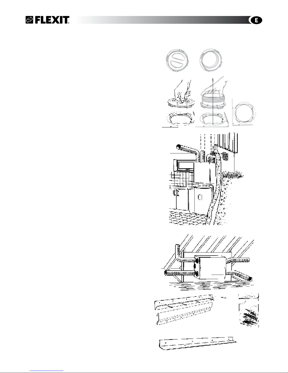
4 Installing SL4 R
The duct connections on the top and bottom of the unit
can be moved by turning the nipples/covers a quarter
turn and lifting them up (Fig. 8).
Fix the movable ducts at the top and bottom of the unit
(extract air and exhaust air) with self-tapping screws
from the installation kit. The location of the screws is
indicated on the ducts.
4.1 Wall Mounting
The enclosed wall bracket is used for wall mounting
(Fig. 8B/8C), which is fixed to the unit. Wall must be
sound insulated (Fig. 2/Chapt. 2).
The wall must be sound insulated to prevent noise
transfer. The unit should be placed against a wall which
does not have a sound sencitive adjoining room.
Duct connection top (Fig. 9)
• The wall bracket (Fig. 10B) is screwed to the wall with
the enclosed screws (Fig. 10D).
• The unit is suspended from the rail. As standard, the
unit has the mounting bracket mounted on the top
for 90o installation.
• Fix the unit at the bottom with the enclosed
mounting bracket (Fig. 10E).
Duct connection to the side (Fig. 10)
• For 180o/sideways installation, the mounting bracket
(Fig. 10C) must be unscrewed and installed on the
long side which faces up.
• The suspension rail (Fig. 10B) is screwed to the wall
with the enclosed screws (Fig. 10D).
• The unit is suspended from the rail.
• Fix the unit at the bottom with the enclosed
mounting bracket (Fig. 10E).
Fig. 9
Fig. 10A
Fig. 10B
Fig. 10D
Fig. 10C
Fig. 8
Fig. 10E
SL4 R
gpd.sunwayinfo.com.cngpd.sunwayinfo.com.cn
8
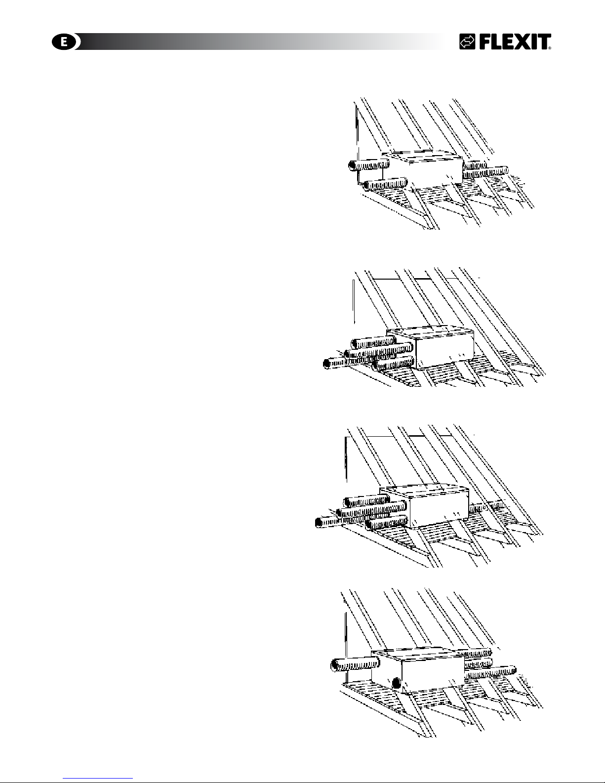
Fig. 11
Fig. 12
Fig. 13
Fig. 14
4.2 Horizontal Mounting
The ventilation unit should be installed on a firm base
(e.g. gypsum/chipboard) that is level.
If the room is noise sensitive, place the panel on a
very firm panel of mineral wool for additional sound
reduction (Fig. 2/Kap. 2). The unit should not be
installed above a bedroom. The figures 11-14 describe
the various duct connections available.
SL4 R
Right hand model
The left model is inverted
Right hand model
The left model is inverted
Left hand model
The right model is inverted
Left hand model
The right model is inverted
gpd.sunwayinfo.com.cngpd.sunwayinfo.com.cn
9
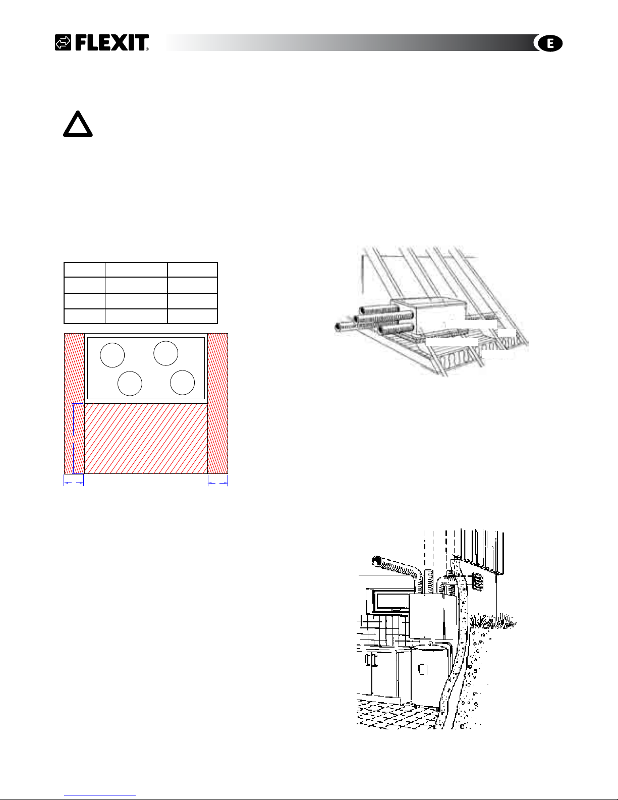
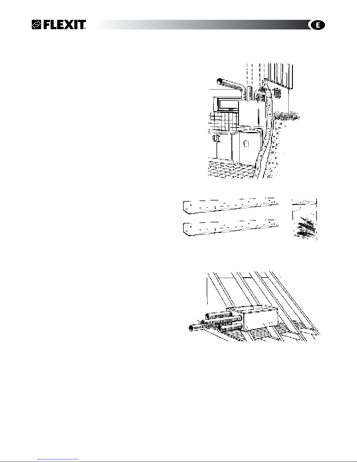
5 Mounting of S4 R/S7 R
These units are heavy and therfore it is necessary
to use additional studs (transcoms) between the
pillars on 48 x 98 mm, or 48 x 148 mm for suspension
above and support bracket below (c/c distance 900
mm) If using existing wall framework, mount an 18
mm plywood wallboard first to distribute the weight,
minimum the seize of the unit.
The wallboard must be secured to the framework in at
least 3 places with countersunk screws (6 attachment
screws 4.5 x 50 are included).
Mounting alternatives for the unit:
• Wall mounting (Fig. 15)
• Horizontal mounting (17)
5.1 Wall Mounting
The enclosed wall brackets are used for wall mounting
(Fig. 14A/14B). The wall must be sound insulated to
prevent noise transfer. The unit should be placed
against a wall which does not have a sound sencitive
adjoining room.
Duct connection top (Fig. 16)
• Attach one of the 2 mounting brackets (Fig. 16A) to
the ventilation unit with the enclosed screws (Fig.
16B).
• Lift the unit onto the wall and fasten with screws.
• Fix the unit at the bottom with the second enclosed
mounting bracket (Fig. 16A).
5.2 Horizontal Mounting
The ventilation unit should be installed on a firm base
(e.g. gypsum/chipboard) that is level.
If the room is noise sensitive, place the panel on a
very firm panel of mineral wool for additional sound
reduction (Fig. 2/Kap. 2). The unit should not be
installed above a bedroom.
Fig. 15
Fig. 16B
Fig. 16A
S4 R/S7 R
Fig. 17
gpd.sunwayinfo.com.cngpd.sunwayinfo.com.cn
10
COMMON
6 Connections of ducts and electrical
connection
• The ducts usually come from joists and are
connected to the nipples on the top of the unit.
• Ensure that the ducts are connected to the right
nipple. See the labelling on the unit (top/bottom
and behind door). The symbols are explained on
page 3 and the placing is shown on measurement
drawing in Chap. 1.
• Pull the duct insulation well up to the unit.
• To avoid condensation, it is very important for the
outdoor air duct to have insulation and a plastic
sleeve pulled right down to the unit. Seal the plastic sleeve to the unit with tape.
The outdoor air duct is normally designed with 25
mm insulation.
• Lay the outdoor air duct with a slight incline towards the outdoor air cap so that any water that
enters drains out again.
• With a short distance between the unit and the
exhaust point, sound insulation must be installed
to meet the requirements for the outdoor sound
level.
• Ducts must have good sound insulation, particularly above the unit.
• All electrical connections must be made by qualified personell only.
The unit must be equipped with a separate
earth-leakage circuit-breaker.
Power Cord
The unit is supplied with a 1.8 m cable and plug (which
also functions as the service switch). The cable emerges on the top of the unit (front) on the left side of a right
model and the right side of a left model. This is connected to a 230 V 50 Hz single-phase earthed power
point that is located in an easily accessible position
close by. For fuse types, see chapt. 14.
6.1 Automatics
The control package is supplied with the unit. The lowvoltage cable must be laid between the unit and the
switch unit. See separate automatics documentation.
The low-voltage cable must be laid at least
30 cm away from the 230 V cable. For flush installation, lay the cable in 20 mm conduit pipe.
6.2 Supply Air Temperature Sencor (B1)
Temperature sensor B1 must be placed after
the water battery.
This should be placed in the supply air duct (red on Flexit
Drawing/
Symbold Used
page 3) approx. 1 m from the unit.
Roll out the marked wire coil on the unit located close to
the supply air intake. Drill a Ø 7 mm hole in the duct where
the sencor can be placed. Seal the hole with a sealant and
tape the wire on the outside of the duct to keep in place.
6.3 Temperature sensor for water battery (B5)
In order to avoid that the water battery is destroyed by
frost a temperature sensor (B5) must be installed on the
return water pipe where the cold water leaves the battery.
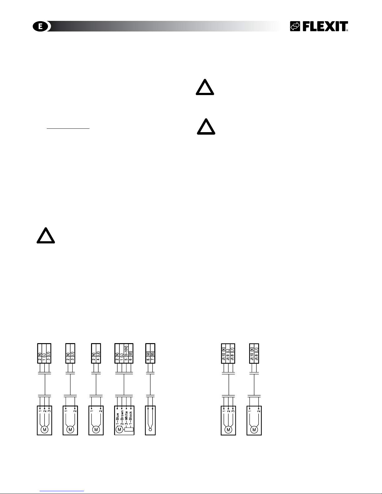
6.4 External Components
Refer to separate electrical circut drawing enclosed
with the individual ventilation unit and Fig. 18 below.
Water models Electrical models
Connected to external box Connected directely on the mainvboard
Damper motor 230V
3-wires
Damper motor 230V
2-wires
Pump motor 230V
Vent motor 230V
3-way vent
B5 Temperature sensor
Water battery
Damper motor 230V
3-wires
Damper motor 230V
2-wires
Fig. 18
gpd.sunwayinfo.com.cngpd.sunwayinfo.com.cn
11
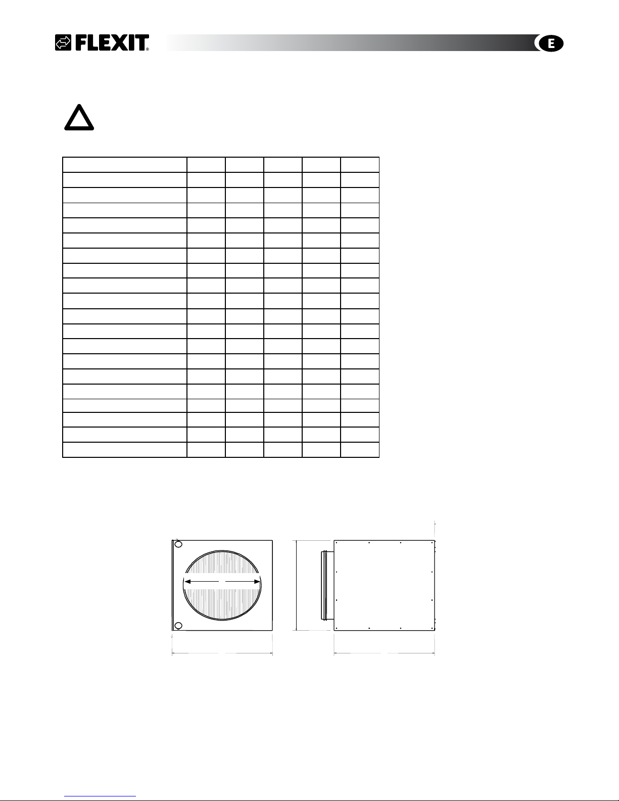
WATER BATTERY
7 Plumbing Works
All plumbing must be performed by a qualified plumber.
7.1 Technical Spesifications Water Battery
Water temp. In °C 80 70 60 50 40
Water temp. Out °C 60 50 40 30 30
S4R/SL4R
Water pressure l/s 0,03 0,03 0,02 0,02 0,02
Pressure drop waterside kPa 2,99 1,98 1,1 1,24 1,8
Max battery capasity kW 2,86 2,23 1,56 1,25 1
Max temp. increase °C 23,4 18,2 12,8 10,2 8,2
Pipe connection Ø mm 10 10 10 10 10
Recommended kvs-value 1,0 1,0 1,0 1,0 1,0
S7R
Water pressure l/s 0,08 0,06 0,05 0,03 0,06
Pressure drop waterside kPa 17,85 12,58 8,04 4,25 12,97
Max battery capasity kW 6,19 5,01 3,82 2,6 2,42
Max temp. increase °C 29,5 23,9 18,25 12,4 11,5
Pipe connection Ø mm 1/2” 1/2” 1/2” 1/2” 1/2”
Recommended kvs-value 1,6 1,6 1,6 1,0 1,0
PHYSICAL DIMENSIONS
A B C D
S4R/SL4R mm 205 205 350 160
S7R mm 351 255 350 200
Fig. 20 Duct battery
D
B
C
A
gpd.sunwayinfo.com.cngpd.sunwayinfo.com.cn
12
7.2 Possible Valve Types
3-way valve, type Belimo DN15:
Article no. 56597 Kvs 1,6
Article no. 56604 Kvs. 1,0
7.3 Possible Vent Motors
Vent motor type Belimo L230A-SR, 0-10V.
Article no. 56596.
24V motor can not be used
7.4 Placement of Duct Battery
The duct battery must be placed horizontally (Fig. 20/
Chapter 8.1). When placed in an non-insulated room
the battery itself must be insulated.
S4 R/SL4 R 14466
S7 R 14467
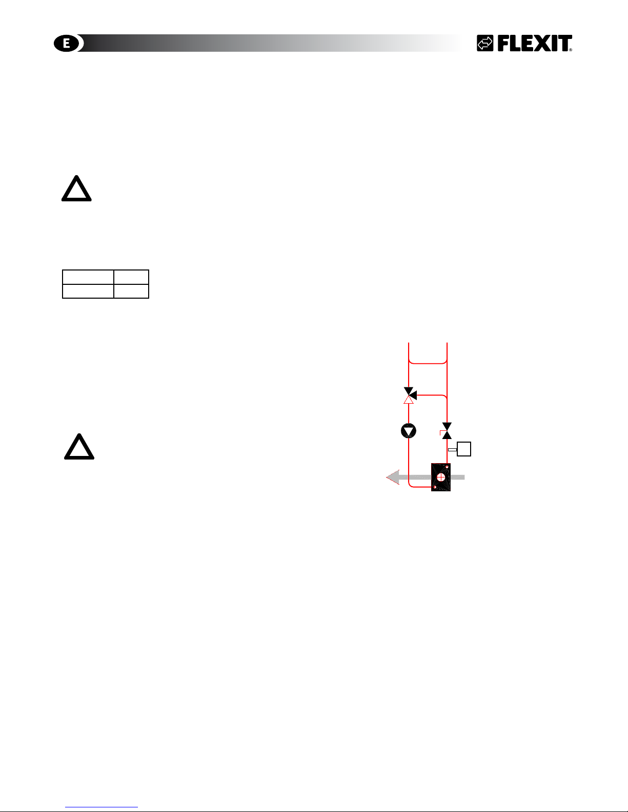
7.5 Connections
Use the recommended connection (see Fig. 20) unless
specified otherwise. The water supply must be at the
bottom of the water battery - the return must be on
the top.
Place the adjustment valve as close to the unit as
possible. (Please note that many valve motors can go
in both directions and this can be set on the motor.
Set it so that the valve opens on an increasing 0-10 V
signal.)
Before connecting the water battery, it
is necessary to check that the inspection
doors are accessible and there is space
enough to change the water battery.
If you use a water battery that has not had glycol
(or another antifreeze) added, the unit should be in
a heated room on account of the risk of frost in the
battery. Install air dampers with spring-loaded return
for outdoor air. Place the unit close to a gully to avoid
damage caused by any water leaks.
Fig. 21 Recommended connection
Pump
Throttle valve
3-way valve
Hot water from
boiler system
Water battery in the
supply air system
WATER BATTERY
B5
gpd.sunwayinfo.com.cngpd.sunwayinfo.com.cn

13
FI2
M1
M2
EB1
F10
F20
M4
HR-R
FI1
B1
8 General Pictures/System Drawings
8.1 S3 R
General Picture - Rotor Heat Exchanger
1 (FI2) Extract air filter F 7
2 (FI1) Supply air filter F 7
3 (EB1) Heating battery, electrical
4 (F10-20) Overheating thermostat (manual reset)
5 (M1) Supply air fan
6 (M2) Extract air fan
7 (HR-R) Rotor heat exchanger
8 (M4) Rotor motor
9 Control box
10 Adjustment switch
System Drawing - Electrical Battery
B1 Temperature sensor, supply air
EB1 Heating battery, electrical
F10 Overheating thermostat (manual reset)
F20 Overheating thermostat (automatic reset)
FI1 Supply air filter
FI2 Extract air filter
M1 Supply air fan
M2 Extract air fan
HR-R Rotor heat exchanger
M4 Rotor motor
Extract air Supply Outdoor Exhaust
S3 R/S3 RK
Right model
(left model inverted)
Extract air Supply air Outdoor air Exhaust
6
2
5
1
3
4
9
10
8
7
gpd.sunwayinfo.com.cngpd.sunwayinfo.com.cn

14
8.2 SL4 R
General Picture - Rotor Heat Exchanger
1 (FI2) Extract air filter F 7
2 (FI1) Supply air filter F 7
3 (EB1) Heating battery, electrical
4 (F10-20) Overheating thermostat (manual reset)
5 (M1) Supply air fan
6 (M2) Extract air fan
7 (HR-R) Rotor heat exchanger
8 Control box
9 Adjustment switch
10 Connection: Control panel/kitchen hood
System Drawing - Electrical Battery
B1 Temperature sensor, supply air
B5 Temperature sensor, water battery * (- EB1/F10/F20)
EB1 Heating battery, electrical
F10 Overheating thermostat (manual reset)
F20 Overheating thermostat (automatic reset)
FI1 Supply air filter
FI2 Extract air filter
M1 Supply air fan
M2 Extract air fan
HR-R Rotor heat exchanger
M4 Rotor motor
MODELS WITH KITCHEN HOOD ONLY:
K Kitchen hood (SL4 RK)
System Drawing - Water Battery *
FI2
M1
M2
EB1
VF10
F20
M4
HR-R
FI1
B1
K
Extract Supply Outdoor Exhaust
SL4 R
Supply air Extract air Kitchen hood Outdoor air Exhaust
Right model
(left model inverted)
System Drawing - Electrical Battery
8
6
10
3
2
7
1
4
5
9
FI2
M1
M2
M4
HR-R
FI1
K
B1
B5
gpd.sunwayinfo.com.cngpd.sunwayinfo.com.cn

15
8.3 S4 R/S7 R
General Picture - Rotor Heat Exchanger
1 (FI2) Extract air filter F 7
2 (FI1) Supply air filter F 7
3 (EB1) Heating battery, electrical
4 (F10-20) Overheating thermostat (manual reset)
5 (M1) Supply air fan
6 (M2) Extract air fan
7 (HR-R) Rotor heat exchanger
8 (M4) Rotor motor
9 Control box
10 Adjustment switch (AC)
11 Connection control panel
System Drawing - Electrical Battery
B1 Temperature sensor, supply air
B5 Temperature sensor, water battery
* (- EB1/F10/F20)
EB1 Heating battery, electrical
F10 Overheating thermostat (manual reset)
F20 Overheating thermostat (automatic reset)
FI1 Supply air filter
FI2 Extract air filter
M1 Supply air fan
M2 Extract air fan
HR-R Rotor heat exchanger
M4 Rotor motor
System Drawing - Water Battery *
S4 R/S7 R
Supply air Extract air Exhaust Outdoor air
Supply Extract Exhaust Outdoor
B1
FI2
M1
M2
EB1
F10
F20
FI1
M4
HR-R
Right model
(left model inverted)
1
11
4
5
3
8
6
2
7
10
9
System Drawing - Electrical Battery
B1
FI2
M1
M2
FI1
M4
HR-R
B5
B1
gpd.sunwayinfo.com.cngpd.sunwayinfo.com.cn

16
9 Capasity and sound data
9.1 Capacity Diagram, Sound Data, Specifications - S3 R
0
100
200
300
Pa
m3/h
0
200
0
300
100
0
40 80
W
0
40
80
120
160
l/s
100
60
20
40dB(A)
55dB(A)
45dB(A)
230V
190V
50dB(A)
120V
170V
150V
105V
85V
60V
60V
85V
105V
120V
150V
170V
190V
230V
F5-filter
Pa
24
45
65
0
0
100
200
300
Pa
m3/h
0
200
0
300
100
0
40 80
W
0
40
80
120
160
l/s
100
60
20
Pa
24
45
65
0
83dB(A)
80dB(A)
70dB(A)
230V
150V
190V
105V
75dB(A)
230V
150V
120V
85V
190V
170V
105V
60V
60V
85V
120V
170V
65dB(A)
-11
-28
-53
Water Battery
F5 Filter
S3 R
Supply air side (with F7 filter)
Sound data is given at sound power level LwA in the capacity
diagrams and is corrected with the table below for the various
octave bands. Radiated noise produces Lw in the various octave
bands and total LwA. Radiated noise is estimated by finding the
noise level from the supply air table and deduct the total value
found in the correction factor table below.
Correction factor for Lw
Hz 63 125 250 500 1000 2000 4000 8000 LwA
Supply air 3 2 -2 -5 -5 -6 -13 -29
Extract air 18 14 1 -12 -14 -28 -37 -43
Radiated 47 -42 -40 -43 -44 -45 -49 -57 -38,7
Extract air side (with F7 filter)
Power consumption in Watt
Contact resistance (Pa)
Air flow rate, m3/h - Pressure correction factor
Power consumption in Watt
Contact resistance (Pa)
Air flow rate, m3/h - Pressure correction factor
Data for supply air is measured in accordance with ISO 5136,
"In-duct method".
Radiated noise is measured in accordance with ISO 9614-2.
Bruel & Kjær measuring equipment, type 2260.
Air capacity at various capacity settings in Volt.
Supply air fan power consumption at various capacity settings.
Sound power level Lw
A, cf. correction table.
gpd.sunwayinfo.com.cngpd.sunwayinfo.com.cn

17
9.2 Capacity Diagram, Sound Data, Specifications - SL4 RE/SL4 RW
0
100
200
300
Pa
400
m3/h
0
400
200
0
300
100
0
40 80
W
0
50
100
150
200
l/s
100
60
20
Pa
15 25 35
45
0
65dB(A)
60dB(A)
50dB(A)
230V
150V
120V
85V
190V
170V
105V
60V
55dB(A)
230V
150V
120V
85V
190V
170V
105V
60V
45dB(A)
F5 Filter
0
100
200
300
Pa
400
m3/h
0
400
200
0
300
100
0
40 80
W
0
50
100
150
200
l/s
100
60
20
80dB(A)
75dB(A)
65dB(A)
150V
120V
190V
170V
105V
70dB(A)
150V
85V
190V
170V
105V
60V
60dB(A)
230V
85V
60V
83dB(A)
230V
120V
Pa
15 25 35
45
0
-10 -25
-55
-90
Water Battery
F5 Filter
SL4 R
Supply air side (with F7 filter)
Sound data is given at sound power level LwA in the capacity
diagrams and is corrected with the table below for the various
octave bands. Radiated noise produces Lw in the various octave
bands and total LwA. Radiated noise is estimated by finding the
noise level from the supply air table and deduct the total value
found in the correction factor table below.
Correction factor for Lw
Hz 63 125 250 500 1000 2000 4000 8000 LwA
Supply air
3 1 2 -1 -7 -11 -18 -31
Extract air
10 8 5 -2 -11 -19 -30 -48
Radiated
-50 -40 -34 -42 -46 -47 -56 -63 -38,5
Power consumption in Watt
Contact resistance (Pa)
Air flow rate, m3/h - Pressure correction factor
Power consumption in Watt
Contact resistance (Pa)
Air flow rate, m3/h - Pressure correction factor
Extract air side (with F7 filter)
Data for supply air is measured in accordance with ISO 5136,
"In-duct method".
Radiated noise is measured in accordance with ISO 9614-2.
Bruel & Kjær measuring equipment, type 2260.
Air capacity at various capacity settings in Volt.
Supply air fan power consumption at various capacity settings.
Sound power level Lw
A, cf. correction table.
gpd.sunwayinfo.com.cngpd.sunwayinfo.com.cn

18
9.3 Capacity Diagram, Sound Data, Specifications - SL4 RE EC/SL4 RW EC
77dB(A)
70dB(A)
80%
60%
40%
75dB(A)
65dB(A)
60dB(A)
100%
40%
100%
60%
80%
0
100
200
300
Pa
400
m3/h
0
400
200
0
300
100
0
40 80
W
0
25
50
75
100
l/s
100
60
20
Pa
15 25 35
45
0
-10 -25
-55
-90
Water Battery
F5 Filter
60dB(A)
50dB(A)
80%
60%
40%
55dB(A)
80%
60%
40%
45dB(A)
40dB(A)
100%
100%
0
100
200
300
Pa
400
m3/h
0
400
200
0
300
100
0
40 80
W
0
25
50
75
100
l/s
100
60
20
Pa
F5-filter
15 25 35
45
0
SL4 R
Supply air side (with F7 filter)
Sound data is given at sound power level LwA in the capacity
diagrams and is corrected with the table below for the various
octave bands. Radiated noise produces Lw in the various octave
bands and total LwA. Radiated noise is estimated by finding the
noise level from the supply air table and deduct the total value
found in the correction factor table below.
Correction factor for Lw
Hz 63 125 250 500 1000 2000 4000 8000 LwA
Supply air
9 3 -1 -2 -4 -10 -18 -31
Extract air
13 9 3 -2 -10 -19 -31 -48
Radiated
-43 -35 -32 -40 -43 -45 -55 -63 -36,9
Power consumption in Watt
Contact resistance (Pa)
Air flow rate, m3/h - Pressure correction factor
Power consumption in Watt
Contact resistance (Pa)
Air flow rate, m3/h - Pressure correction factor
Extract air side (with F7 filter)
Data for supply air is measured in accordance with ISO 5136,
"In-duct method".
Radiated noise is measured in accordance with ISO 9614-2.
Bruel & Kjær measuring equipment, type 2260.
Air capacity at various capacity settings in Volt.
Supply air fan power consumption at various capacity settings.
Sound power level Lw
A, cf. correction table.
gpd.sunwayinfo.com.cngpd.sunwayinfo.com.cn

19
9.4 Capacity Diagram, Sound Data, Specifications - S4 RE/S4 RW
0
100
200
300
Pa
400
m3/h
0
400
500
200
0
300
100
0
40 80
120
W
0
50
100
150
200
l/s
100
60
20
Pa
9 17 25
32
0
F5 Filter
62dB(A)
60dB(A)
50dB(A)
55dB(A)
45dB(A)
230V
190V
170V
150V
120V
105V
85V
60V
230V
60V
85V
120V
150V
170V
190V
105V
0
100
200
300
Pa
400
m3/h
0
400
500
200
0
300
100
0
40 80
120
W
0
50
100
150
200
l/s
100
60
20
Pa
9
0
-11 -28
-53
-90
Water Battery
F5 Filter
17
25
32
75dB(A)
70dB(A)
60dB(A)
65dB(A)
55dB(A)
190V
230V
170V
150V
120V
105V
85V
60V
230V
60V
85V
105V
120V
150V
170V
190V
S4 R
Supply air side (with F7 filter)
Sound data is given at sound power level LwA in the capacity
diagrams and is corrected with the table below for the various
octave bands. Radiated noise produces Lw in the various octave
bands and total LwA. Radiated noise is estimated by finding the
noise level from the supply air table and deduct the total value
found in the correction factor table below.
Correction factor for Lw
Hz 63 125 250 500 1000 2000 4000 8000 LwA
Supply air
7 3 -1 -3 -6 -7 -17 -30
Extract air
8 9 5 -2 -11 -21 -29 -48
Radiated
-43 -31 -33 -34 -38 -38 -39 -44 -30,6
Power consumption in Watt
Contact resistance (Pa)
Air flow rate, m3/h - Pressure correction factor
Power consumption in Watt
Contact resistance (Pa)
Air flow rate, m3/h - Pressure correction factor
Extract air side (with F7 filter)
Data for supply air is measured in accordance with ISO 5136,
"In-duct method".
Radiated noise is measured in accordance with ISO 9614-2.
Bruel & Kjær measuring equipment, type 2260.
Air capacity at various capacity settings in Volt.
Supply air fan power consumption at various capacity settings.
Sound power level Lw
A, cf. correction table.
gpd.sunwayinfo.com.cngpd.sunwayinfo.com.cn

20
9.5 Capacity Diagram, Sound Data, Specifications - S4 RE EC/S4 RW EC
S4 R
60dB(A)
50dB(A)
80%
60%
40%
55dB(A)
80%
60%
40%
45dB(A)
40dB(A)
100%
100%
0
100
200
300
Pa
400
m3/h
0
400
200
0
300
100
0
40 80
W
0
25
50
75
100
l/s
100
60
20
Pa
F5-filter
10 15 25
30
0
73dB(A)
70dB(A)
80%
60%
40%
55dB(A)
65dB(A)
60dB(A)
100%
100%
80%
40%
60%
0
100
200
300
Pa
400
m3/h
0
400
200
0
300
100
0
40 80
W
0
25
50
75
100
l/s
100
60
20
Pa
10 15 25
30
0
-10 -25
-55
-90
Water Battery
F5 Filter
Sound data is given at sound power level LwA in the capacity
diagrams and is corrected with the table below for the various
octave bands. Radiated noise produces Lw in the various octave
bands and total LwA. Radiated noise is estimated by finding the
noise level from the supply air table and deduct the total value
found in the correction factor table below.
Correction factor for Lw
Hz 63 125 250 500 1000 2000 4000 8000 LwA
Supply air
10 4 -3 -4 -3 -10 -20 -34
Extract air
11 11 4 -4 -8 -23 -32 -48
Radiated
-43 -43 -31 -33 -34 -38 -39 -44 -30,6
Supply air side (with F7 filter)
Power consumption in Watt
Contact resistance (Pa)
Air flow rate, m3/h - Pressure correction factor
Power consumption in Watt
Contact resistance (Pa)
Air flow rate, m3/h - Pressure correction factor
Extract air side (with F7 filter)
Data for supply air is measured in accordance with ISO 5136,
"In-duct method".
Radiated noise is measured in accordance with ISO 9614-2.
Bruel & Kjær measuring equipment, type 2260.
Air capacity at various capacity settings in Volt.
Supply air fan power consumption at various capacity settings.
Sound power level Lw
A, cf. correction table.
gpd.sunwayinfo.com.cngpd.sunwayinfo.com.cn

21
9.6 Capacity Diagram, Sound Data, Specifications - S7 RE/S7 RW
0
200
400
Pa
l/s
0
40 80
120
160
Pa
0 800
m3/h
600
32
42
0
600
W
0
50
100
150
250
200
200
350
300
-39
Water Battery
F5 Filter
-4
-30
-52
38
9
47
400
200
-22
-14
-8
25
17
80dB(A)
75dB(A)
70dB(A)
65dB(A)
230V
150V
120V
85V
190V
170V
105V
60dB(A)
83dB(A)
230V
60V
85V
120V
150V
170V
105V
190V
60V
S7 R
Supply air side (with F7 filter)
Sound data is given at sound power level LwA in the capacity
diagrams and is corrected with the table below for the various
octave bands. Radiated noise produces Lw in the various octave
bands and total LwA. Radiated noise is estimated by finding the
noise level from the supply air table and deduct the total value
found in the correction factor table below.
Correction factor for Lw
Hz 63 125 250 500 1000 2000 4000 8000 LwA
Supply air
3 1 -4 -4 -5 -7 -14 -24
Extract air
10 10 11 -4 -9 -15 -26 -41
Radiated
-43 -31 -33 -34 -38 -38 -39 -44 -30,6
Power consumption in Watt
Contact resistance (Pa)
Air flow rate, m3/h - Pressure correction factor
Power consumption in Watt
Contact resistance (Pa)
Air flow rate, m3/h - Pressure correction factor
Extract air side (with F7 filter)
Data for supply air is measured in accordance with ISO 5136,
"In-duct method".
Radiated noise is measured in accordance with ISO 9614-2.
Bruel & Kjær measuring equipment, type 2260.
Air capacity at various capacity settings in Volt.
Supply air fan power consumption at various capacity settings.
Sound power level Lw
A, cf. correction table.
0
200
400
l/s
0
40 80
120
160
0 400 800
m3/h
200 600
600
W
0
50
100
150
250
200
200
350
300
Pa
17 32
42
0
25
38
9
47
F5 Filter
68dB(A)
60dB(A)
55dB(A)
230V
150V
120V
85V
190V
170V
105V
60V
50dB(A)
230V
150V
120V
85V
190V
170V
105V
60V
65dB(A)
45dB(A)
gpd.sunwayinfo.com.cngpd.sunwayinfo.com.cn

22
9.7 Capacity Diagram, Sound Data, Specifications - S7 RE/S7 RW EC
0
200
400
Pa
l/s
0
40 80
120
160
0 400
m3/h
200 600
600
W
0
25
75
100
175
150
200
Pa
15 30
40
0
25
35
9
F5 Filter
125
50
80%
60%
100%
40%
40%
60%
80%
100%
45dB(A)
50dB(A)
55dB(A)
60dB(A)
64dB(A)
0
200
400
Pa
l/s
0
40 80
120
160
0 400
m3/h
200 600
600
W
0
25
75
100
175
150
200
Pa
15 30
40
0
25
35
9
125
50
60dB(A)
65dB(A)
70dB(A)
75dB(A)
80dB(A)
60%
80%
100%
40%
100%
80%
60%
40%
-5 -10
-15
-45
Water Battery
F5 Filter
-25
-35
Supply air side (with F7 filter)
Sound data is given at sound power level LwA in the capacity
diagrams and is corrected with the table below for the various
octave bands. Radiated noise produces Lw in the various octave
bands and total LwA. Radiated noise is estimated by finding the
noise level from the supply air table and deduct the total value
found in the correction factor table below.
Correction factor for Lw
Hz 63 125 250 500 1000 2000 4000 8000 LwA
Supply air
3 1 -4 -4 -5 -7 -14 -24
Extract air
10 11 3 -4 -9 -15 -26 -41
Radiated
-43 -31 -33 -34 -38 -38 -39 -44 -30,6
Power consumption in Watt
Contact resistance (Pa)
Air flow rate, m3/h - Pressure correction factor
Power consumption in Watt
Contact resistance (Pa)
Air flow rate, m3/h - Pressure correction factor
Extract air side (with F7 filter)
S7 R
Data for supply air is measured in accordance with ISO 5136,
"In-duct method".
Radiated noise is measured in accordance with ISO 9614-2.
Bruel & Kjær measuring equipment, type 2260.
Air capacity at various capacity settings in Volt.
Supply air fan power consumption at various capacity settings.
Sound power level Lw
A, cf. correction table.
gpd.sunwayinfo.com.cngpd.sunwayinfo.com.cn

23
10 Installation of External Kitchen
Hood
10.1 Technical Data
Width: 60 cm
El. connection: 230 V earthed
Light: Fluorescent tube, base G23, 11 W
10.2 Installation of External Kitchen Hood
Installing the sleeve and damper
The sleeve is inside the volume hood on delivery.
Place the damper shaft A in the hoop under the
damper lid, see Fig. 21. Ensure that the grips B are
under the edge of the plate. The sleeve snaps into
place.
Installing the kitchen hood
The kitchen hood must be placed under or recessed
in the row of cabinets, see Fig. 22. The distance
between the cooker and the kitchen hood must be at
least 40 cm. For a gas cooker, the distance must be
65 cm. The kitchen hood can also be installed using
wall mountings that can be purchased as accessories,
Fig. 13. Instructions for installing the accessories are
enclosed with them.
Electrical installation
The kitchen hood is supplied with a cable and earthed
plug for connection to an earthed socket. The control
cable (12 V) is connected between marked 2-core
cables from the kitchen hood and the unit. The colour
of the cables connected to the terminals is of no
significance. The control cable between the kitchen
hood and the unit must at least be of type 2 x 0.75
mm2. The voltage between the units is 12 V DC.
The installation must be carried out by an
authorised expert.
Adjustment
For adjustment of the kitchen hood, see Chap. 12, and
for the unit see Chap. 13 Adjustment Curves.
Fig. 21
Fig. 23
Fig. 22
gpd.sunwayinfo.com.cngpd.sunwayinfo.com.cn

24
11 Adjusting the Kitchen Hood
11.1 Basic Ventilation
The basic ventilation is adjusted by setting the sliding damper A to the desired position as shown in detail B in Fig. 24
(see diagram 13.1).
11.2 Forced Ventilation
Open the damper and remove the throttle piece C, Fig. 25. Adjust the forced ventilation by cutting out a suitable
number of rings in the throttle piece, Fig. 26 (see diagram 13.2). Ensure that the guide slot D is in position when the
piece is in place.
11.3 Pressure Drop Measurement
The pressure drop is measured by the hose being fitted to the measuring outlet at the front of the damper, Fig. 27.
The pressure drop corresponds to the axis in the adjustment diagram (left side), see Chap. 13.
If basic ventilation is not required, the enclosed piece can be installed, see Fig. 28 for the procedure.
Fig. 25
Fig. 27
Fig. 24
Fig. 26
Fig. 28
gpd.sunwayinfo.com.cngpd.sunwayinfo.com.cn

25
12 Adjustment Curves External Kitchen Hood
12.1 Basic Ventilation S3 R
12.2 Forced Ventilation S3 R
S3 R
0 - Open = Number of rings removed
100/150/200 Pa = Total duct resistance for the extract air and exhaust
air side
Lw (A) measured 1 m from the kitchen hood varies between 46 and 48
dB(A) throughout the measuring area
S3 R/S3 RK
S3 R
Min. - Max. = Damper position
dB = Lp(A) measured 1 m from the kitchen hood in the kitchen landscape.
0
50 Pa
100
150
200
250
300
350
0 20 40 60 80 100 m³/h
Min
Max
6
54
3
2
7
8
9
10
11
35 dB(A)
32 dB(A)
30 dB(A)
25 dB(A)
Pa 125
175
225
275
325
125
175 225
275 m³/h
0
Open
5
4
3
2
1
200 Pa
150 Pa
100 Pa
gpd.sunwayinfo.com.cngpd.sunwayinfo.com.cn

26
12.3 Basic Ventilation SL4 R/SL4 R EC
12.4 Forced Ventilation SL4 R/SL4 R EC
0
50 Pa
100
150
200
250
300
0 20 40 60 80 100 m³/h
Min
Max
6
5
4
3
2
7
8
9
10
11
35 dB(A)
32 dB(A)
30 dB(A)
26 dB(A)
SL4 R
Min. - Max. = Damper position
dB = Lp(A) measured 1 m from the kitchen hood in the kitchen landscape.
SL4 R
0 - Open = Number of rings removed
100/150/200 Pa = Total duct resistance for the extract air and exhaust
air side
Lw (A) measured 1 m from the kitchen hood varies between 45 and 49
dB(A) throughout the measuring area
0
5
4
3
2
1
200 Pa
150 Pa
100 Pa
Open
Pa 75
125
175
225
275
125
175 225
275
m³/h
325
0
50 Pa
100
150
200
250
300
0 20 40 60 80 100 m³/h
Min
2
30 dB(A)
28 dB(A)
32 dB(A)
35 dB(A)
3
Max
4
5
6
7
8
9
10 11
0
5
4
3
2
1
200 Pa
150 Pa
100 Pa
Open
Pa 50
100
150
200
250
100
150 200
250
m³/h
300
SL4 R EC
Min. - Max. = Damper position
dB = Lp(A) measured 1 m from the kitchen hood in the kitchen landscape.
SL4 R EC
0 - Open = Number of rings removed
100/150/200 Pa = Total duct resistance for the extract air and exhaust
air side
Lw (A) measured 1 m from the kitchen hood varies between 45 and 49
dB(A) throughout the measuring area
SL4 R
gpd.sunwayinfo.com.cngpd.sunwayinfo.com.cn

27
13 Technical Spesifications
13.1 Technical Spesifictions S3 R
S3 R
Rated voltage 230 V/50 Hz
Fuse 10 A
Rated current, total 5,5 A
Rated power, total 1271 W
Rated power, electric batteries 900 W
Rated power, fans 2 x 165 W
Fan type F-wheel
Fan motor control Transformer
Max. fan speed 2230 o/min
Automatic control standard CS 50
Filter type (SUP/EXTR) F7/F7
SUP filter dimensions (WxHxD) 285x130x50 mm
EXTR filter dimensions (WxHxD) 285x130x50 mm
Weight 38,5 kg
Duct connection
Ø 125 mm
(127 mm muffe)
Height 700 mm
Width 598 mm
Depth 320 mm
13.2 Technical Spesifictions SL4 R
SL4 RE SL4 RE EC SL4 RW SL4 RW EC
Rated voltage 230 V/50 Hz 230 V/50 Hz 230 V/50 Hz 230 V/50 Hz
Fuse 10 A 10 A 10 A 10 A
Rated current, total 5,5 A 4,8 A 1,6 A 0,9 A
Rated power, total 1271 W 1107 W 371 W 207 W
Rated power, electric batteries 900 W 900 W - -
Rated power, fans 2 x 165 W 2 x 83 W 2 x 165 W 2 x 83 W
Fan type F-wheel F-wheel F-wheel F-wheel
Fan motor control Transformer EC-stepless Transformer EC-stepless
Max. fan speed 2230 o/min 1970 o/min 2230 o/min 1970 o/min
Automatic control standard CS 50 CS 50 CS 50 CS 50
Filter type (SUP/EXTR) F7/F7 F7/F7 F7/F7 F7/F7
SUP filter dimensions (WxHxD) 350x185x50 mm 350x185x50 mm 350x185x50 mm 350x185x50 mm
EXTR filter dimensions (WxHxD) 350x185x50 mm 350x185x50 mm 350x185x50 mm 350x185x50 mm
Weight 48 kg 48 kg 48 kg 48 kg
Duct connection Ø 160 mm Ø 160 mm Ø 160 mm Ø 160 mm
Duct connection, kitchen hood Ø 125 mm Ø 125 mm Ø 125 mm Ø 125 mm
Height 700 mm 700 mm 700 mm 700 mm
Width 598 mm 598 mm 598 mm 598 mm
Depth 455 mm 455 mm 455 mm 455 mm
gpd.sunwayinfo.com.cngpd.sunwayinfo.com.cn

28
13.3 Technical Data S4 R
S4 RE S4 RE EC S4 RW S4 RW EC
Rated voltage 230 V/50 Hz 230 V/50 Hz 230 V/50 Hz 230 V/50 Hz
Fuse 10 A 10 A 10 A 10 A
Rated current, total 6,8 A 6,1 A 1,6 A 0,9 A
Rated power, total 1581 W 1417 W 381 W 217 W
Rated power, electric batteries 1200 W 1200 W - -
Rated power, fans 2 x 165 W 2 x 83 W 2 x 165 W 2 x 83 W
Rated power, pre-heating
- - - -
Fan type F-wheel F-wheel F-wheel F-wheel
Fan motor control Transformer EC-stepless Transformer EC-stepless
Max. fan speed 2230 o/min 1970 o/min 2230 o/min 1970 o/min
Automatic control standard CS 50 CS 50 CS 50 CS 50
Filter type (SUP/EXTR) F7/F7 F7/F7 F7/F7 F7/F7
SUP filter dimensions (WxHxD) 468x200x70mm 468x200x70mm 468x200x70mm 468x200x70mm
EXTR filter dimensions (WxHxD) 468x200x70 mm 468x200x70mm 468x200x70mm 468x200x70mm
Weight 85 kg 85 kg 85 kg 85 kg
Duct connection Ø 200 mm Ø 200 mm Ø 200 mm Ø 200 mm
Height 900 mm 900 mm 900 mm 900 mm
Width 900 mm 900 mm 900 mm 900 mm
Depth 550 mm 550 mm 550 mm 550 mm
13.4 Technical Data S7 R
S7 RE S7 RE EC S7 RW S7 RW EC
Rated voltage 230 V/50 Hz 230 V/50 Hz 230 V/50 Hz 230 V/50 Hz
Fuse 13 A 13 A 10 A 10 A
Rated current, total 10,7 A 8,9 A 3,3 A 1,5 A
Rated power, total 2464 W 2045 W 765 W 345 W
Rated power, electric batteries 1700 W 1700 W - -
Rated power, fans 2 x 375 W 2 x 175 W 2 x 375 W 2 x 175 W
Rated power, pre-heating
- - - -
Fan type F-wheel F-wheel F-wheel F-wheel
Fan motor control Transformer EC-stepless Transformer EC-stepless
Max. fan speed 2000 o/min 2000 o/min 2000 o/min 2000 o/min
Automatic control standard CI 50/CU 500* CI 50/CU 500* CI 50/CU 500* CI 50/CU 500*
Filter type (SUP/EXTR) F7/F7 F7/F7 F7/F7 F7/F7
SUP filter dimensions (WxHxD) 468x200x70 mm 468x200x70 mm 468x200x70 mm 468x200x70 mm
EXTR filter dimensions (WxHxD) 468x200x70 mm 468x200x70 mm 468x200x70 mm 468x200x70 mm
Weight 92 kg 92 kg 92 kg 92 kg
Duct connection Ø 200 mm Ø 200 mm Ø 200 mm Ø 200 mm
Height 900 mm 900 mm 900 mm 900 mm
Width 900 mm 900 mm 900 mm 900 mm
Depth 550 mm 550 mm 550 mm 550 mm
* CI 50: Control Panel, CU 500: Circuit Board
gpd.sunwayinfo.com.cngpd.sunwayinfo.com.cn

29
S3 R Right model
S3 R Left model
S4 R/S7 Right model S4 R/S7 R Left model
SL4 R Right model
SL4 R Left model
Unit top - air flow direction
Kitchen Hood
Unit bottom - air flow direction
Kitchen Hood
COMMON
Kitchen Hood
14 Final Check
Control that:
• The duct insulation is in accordance with the manual and the technical documents
• Ducts are connected to the right nipples – check against the unit drawings below
• Adjustment has been carried out in accordance with the manual and ventilation data documentation
• The unit operates normally at all stages
• Heating switches on
The installer may be held liable for any incorrect or defective installation.
Kitchen Hood
gpd.sunwayinfo.com.cngpd.sunwayinfo.com.cn

30
15 Important Safety Instructions
To reduce the risk of fire, electric shock or
injury, read all the safety instructions and
warning texts before using the unit.
• This unit is only designed for ventilation air in
buildings.
• It must not be used to extract combustible or
flammable gases.
• Remove the power plug before commencing any
service and maintenance work.
• Before you open the door, the unit must be dead
and the fans must have been given time to stop
(min. 3 minutes).
• The unit contains heating elements that must not be
touched when they are hot.
• The unit must not be operated without the filters
being in place.
• Do not cook any combustible substances or flame
anything under the fan (only when a kitchen hood is
connected).
• Do not leave a saucepan or frying pan containing oil
or grease unsupervised (only when a kitchen hood is
connected).
• Follow the instructions in the user manual.
To maintain a good indoor climate, comply
with regulations and, to avoid condensation damage, the unit must never be
stopped apart from during service/maintenance or in connection with an accident.
16 Functional Description
In the (HR-R) rotor, the cold outdoor air and the warm
extract air pass each other without being mixed. With
this principle, a large part of the heat in the extract
air will be transferred to the supply air (see drawings
in Chap. 8). If the outdoor temperature is extremely
low, a thermostat-controlled (EB1) heating element
will also ensure that the supply air has the desired
temperature. This supply air is passed via ducts and
valves to living rooms and bedrooms. The extract air is
extracted either from the same room or via door gaps/
overflow gratings to toilets and wet rooms. The used
air is passed via a duct system back to the unit, emits
heat and is blown out of the building via a roof hat or
wall grating.
The temperature of the supply air is controlled by the
rotor. Only when the rotor is not able to maintain the
set temperature, will the heating element start up.
When there is no need for heating (for example in the
summer), the rotor will stop.
16.1 Heating Elements
The heating elements are protected against
overheating by the (F20) overheating thermostat,
which switches off at 60 °C. As an additional safety
measure, the (F10) overheating thermostat switches
off at 85 °C. The F10 overheating thermostat can be
reset manually by pressing the reset button.
You will find the thermostat by opening the unit doors
(located right above the heating element).
16.2 Operation via Kitchen Hood (SL4 R)
A - Knob for damper/timer
B - Pushbutton for light
Open the damper when preparing food. The damper
closes automatically after a maximum of 60 minutes
or if you turn the damper knob to
as shown in Fig.
29. When the timer is activated, the air handling unit is
forced in addition to the damper function.
This is purely a ventilation system and
not a heating system. The home must
be heated in the normal manner. The
heat gained from heat recovery must
be seen in relation to a situation in
which the extract air is blown right out
of the home without recovery.
!
Fig. 29
USER GUIDE
gpd.sunwayinfo.com.cngpd.sunwayinfo.com.cn

31
S3 R
17 Cleaning - Maintenance, S3 R
Before opening the door of the heat recovery system or carrying out maintenance on the
kitchen hood: switch off the heat, let the fans continue for three minutes to remove hot air,
remove the power from the unit and wait 2 minutes before opening the doors.
Fans: Item nos. 6 and 7/Chap. 9 General Drawing. The fans must be cleaned once pr. year. The fans are
cleaned with a small brush and compressed air, if available. NB! Do not use water. Dismantle the
fan as follows: Open the doors as instructed. Pull out the electric quick-release contact for the
motor. Unscrew 2 screws at the front of the motor’s mounting plate. The fan can then be pulled
carefully down and out of the unit.
Filters: To preserve a healthy indoor environment, it is important to change filters when they are dirty.
Dirty filters lead to:
Increased air resistance in the filter – less air in the home – the risk of bacterial growth in
the filter – in the worst case scenario, the system can be damaged.
How often the filters need to be changed depends on the degree of contamination of the air where
they are installed. In general, the filters need to be changed once a year, preferably in the autumn
(after the pollen season). In areas with a lot of dust and contamination, the filters should be
changed in the spring and autumn. The supply air filter and extract air filter (2 and 1) consist of a
compact filter (F7). These are pushed into place.
It is recommended that you order a filter subscription to ensure full benefit from the system and the
cheapest prices.
Order no. for a complete set of filters: 12328
When changing filter, please perform an overall check of the ventilation unit.
Rotor: As the system has filters installed with a high tightness class, it is not normally necessary to clean
the rotor. If, for various reasons, it should still be necessary, dust can be removed with a soft
brush. Further cleaning is possible if you remove the rotor, spray it with fat-soluble detergent and
then blow it clean from the opposite side. Distance approximately 60mm and max. pressure 80
bar. Ensure that the motor is not exposed to water during cleaning. Ensure that all seals around
the rotor are intact and tight.
Do not use detergent that is harmful to aluminium or the environment.
Valves and
duct system: Clean the valves at least once a year. The duct system must be cleaned at least every 10 years.
Outdoor air
intake: Check once a year that the grille is not clogged.
Roof hat: Check once a year that the drainage gap at the bottom is not clogged with leaves. This applies
only if the system has a roof hat.
Filter location
(the drawing shows the left model/the right model is inverted)
Supply air filter:
Compact filter
Rotor
Extract air filter:
Compact filter
!
!
gpd.sunwayinfo.com.cngpd.sunwayinfo.com.cn

32
SL4 R
!
!
18 Cleaning - Maintenance SL4 R
Before opening the door of the heat recovery system or carrying out maintenance on the kitchen
hood: Switch off the heat, let the fans continue for three minutes to remove hot air, remove the
power from the unit and wait 2 minutes before opening the doors.
Fans: Item pos. 5 and 6/Chap. 9 General Drawing, SL4 R. The fans must be cleaned once pr. year. The
fans are cleaned with a small brush and compressed air, if available. Remove the fans as follows:
(Fan item no. 6) Remove the cover in front of the fan by pressing the snap locks at the bottom
of the cover. For both fans: pull the fan out of the track and disconnect the contact. The motor
and fan blades are removed by unscrewing the 4 screws in the round motor plate and carefully
pulling the motor out of the motor housing. Mounting takes place in the reverse order.
Filters: To preserve a healthy indoor environment, it is important to change filters when they are
clogged/dirty. Clogged filters lead to:
Increased air resistance in the filter – less air in the home – the risk of bacterial growth in
the filter – in the worst case scenario, the system can be damaged.
How often the filters need to be changed depends on the degree of contamination of the air
where they are installed. In general, the filters need to be changed once a year, preferably in
the autumn (after the pollen season). In areas with a lot of dust and contamination, the filters
should be changed in the spring and autumn.
The supply air filter, which cleans the outdoor air (item no. 2) is a compact filter (filter class F7).
The filter is pushed in place in the fixing rails. The extract air filter (item no. 1) is a compact filter
(filter class F7) and is located in its own drawer which can be pulled right out after the finger
screws have been removed. We recommended that you order a filter subscription for full benefit
from the system and the cheapest prices.
Order no. for a complete set of filters: 12336
When changing filter, please perform an overall check of the ventilation unit.
Rotor: As the system has filters installed with a high tightness class, it is not normally necessary to
clean the rotor. If, for various reasons, it should still be necessary, dust can be removed with
a soft brush. Further cleaning is possible if you remove the rotor, spray it with fat-soluble
detergent and then blow it clean from the opposite side. Distance approximately 60mm and max.
pressure 80 bar. Ensure that the motor is not exposed to water during cleaning. Ensure that all
seals around the rotor are intact and tight.
Do not use detergent that is harmful to aluminium or the environment.
Valves and
duct system: Clean the valves at least once a year. The duct system must be cleaned at least every 10 years.
Outdoor air
intake: Check once a year that the grille is not clogged.
Roof hat: Check once a year that the drainage gap at the bottom is not clogged with leaves. This applies
only if the system has a roof hat.
Filter location
(the drawing shows the right
model/the left model is inverted)
Rotary wheel-type heat exchanger
Supply air filter
Extract air filter
gpd.sunwayinfo.com.cngpd.sunwayinfo.com.cn

33
S4 R/S7 R
19 Cleaning - Maintenance S4 R/S7 R
Before opening the door of the heat recovery system or carrying out maintenance on the kitchen
hood: switch off the heat, let the fans continue for three minutes to remove hot air, remove the
power from the unit and wait 2 minutes before opening the doors.
Doors: Opened by unscrewing the two screws in one door.
Fans: Item nos. 5 and 6/Chap. 9 General Drawings. The fans must be cleaned once pr. year. The fans are
cleaned with a small brush and compressed air, if available. NB! Do not use water. Disassemble as
follows: Open the doors as directed. Pull out the electric quick-release contact for the motor. Unscrew
2 screws under the front edge of the motor’s mounting plate. The fan can then be carefully pulled down
and out of the unit.
Filters: To preserve a healthy indoor environment, it is important to change filters when they are dirty. Dirty
filters lead to:
Increased air resistance in the filter – less air in the home – the risk of bacterial growth in the
filter – in the worst case scenario, the system can be damaged.
How often the filters need to be changed depends on the degree of contamination of the air where they
are installed. In general, the filters need to be changed once a year, preferably in the autumn (after the
pollen season). In areas with a lot of dust and contamination, the filters should be changed in the spring
and autumn. The supply air filter and extract air filter (2 and 1) consist of an EU 3 prefilter on top (coarse
filter) and a compact filter (EU7). They are pushed into place and fastened with filter tighteners.
It is recommended that you order a filter subscription to ensure full benefit from the system and the
cheapest prices.
Order no. for a complete set of filters: 12327
When changing filter, please perform an overall check of the ventilation unit.
Rotor: As the system has filters installed with a high tightness class, it is not normally necessary to clean
the rotor. If, for various reasons, it should still be necessary, dust can be removed with a soft brush.
Further cleaning is possible if you remove the rotor, spray it with fat-soluble detergent and then blow
it clean from the opposite side. Distance approximately 60mm and max. pressure 80 bar. Ensure that
the motor is not exposed to water during cleaning. Ensure that all seals around the rotor are intact
and tight.
Do not use detergent that is harmful to aluminium or the environment.
Valves and
duct system: Clean the valves at least once a year. The duct system must be cleaned at least every 10 years.
Outdoor air
intake: Check once a year that the grille is not clogged.
Roof hat: Check once a year that the drainage gap at the bottom is not clogged with leaves. This applies only if
the system has a roof hat.
!
!
Rotary wheel-type exchanger
Supply air filter:
Prefilter and
compact filter
Extract air filter:
Prefilter and
compact filter
Rotor model filter location
(the drawing shows the right
model/the left model is inverted)
gpd.sunwayinfo.com.cngpd.sunwayinfo.com.cn

34
20 Fault Location
If a power failure occurs the ventilation unit will return to the factory settings when restarting.
For other types of errors which are indicated on the control panel/hand terminal, please refer to
separate automatics manuals.
If non of these measures solves the trouble, contact your supplier for service.
Please report the model type and serial number (found on the sign inside the ventilation unit/
open door).
Error:
The fans do not function and/
or:
Do the following:
Control panel (Chap.
18) is turned off
- Check that the power cord is correctly inserted in the outlet
- Check that the fuses in the fuse box are active
- Check the cable between control panel and ventilation unit
Cannot be adjusted - Deactivate forced ventilation from kitchen hood if connected to unit
The air quantity is considerably
reduced
Do the following:
- Filter (Pos.no. 1, 2/Kap. 9) my be clogged with dirt.
Clean or change, see Cleaning - maintenance
- Fan wheel must be cleaned, see Cleaning - maintenance
COMMON
gpd.sunwayinfo.com.cngpd.sunwayinfo.com.cn

35
21 CE Declaration of Conformity
This declaration confirms that the products meet the requirements in the following Council Directives and
standards:
2004/108/EC Electromagnetic Compatibility (EMC)
2006/95/EC Low-voltage Directive (LVD)
2006/42/EC Machinery Directive (Sikkerhet)ikkerhet)
Producer: FLEXIT AS, Televeien 15, N-1870 Ørje
Type: S3 R 2005 Ventilation Units
SL4 R 2006 Ventilation Units
S4 R 2002 Ventilation Units
S7 R 2002 Ventilation Units
Complies with the
following standards:
The product is CE-marked: Shown in the list above
FLEXIT AS 2010-02-12
Frank Petersen
General Manager
The right to give notice of lack of conformity applies to this product in accordance with the existing terms of sale,
provided that the product is used
correctly and maintained.
Filters are consumables.
The symbol on the product shows that this product must not be treated as household waste. It must be taken to a reception station for
recirculation of electric and electronic equipment.
By ensuring the correct disposal of the equipment, you will contribute to preventing the negative consequences for the environment and
health that incorrect handling may entail. For further information on recirculation of this product, please contact your local authority, your
refuse collection company or the company from which you purchased it.
Notice of lack of conformity as a result of incorrect or defective installation must be submitted to the installation company responsible. The right to
give notice of lack of conformity may lapse if the system is used incorrectly or maintenance is grossly neglected.
Safety Standard EN 60335-1:2002
EMF Standard: EN 50366:2003
EMC Standard: EN 55014-1.2000
EN 61000-3-2:2000
EN 61000-3-3:1995
EN 55014-2:2:1997
COMMON
gpd.sunwayinfo.com.cngpd.sunwayinfo.com.cn

36
22 Product/Environmental Declaration
The declaration applies to the Flexit S3 R, SL4 R, S4 R and S7 R ventilation units
Materials:
Materials with which the user or treated air come into contact:
• The unit’s outer walls are made of galvanised steel DX51D+Z275 (NS-EN 10142)
• The rotary wheel-type heat exchanger, made of aluminium
• Miscellaneous electric cables with PVC insulation
• Electric motors consisting of galvanised steel, aluminium and copper
• Heating elements made of steel
• Air filters of glass fibre, cardboard and EVA melting glue
Materials in the unit with which service personnel may come into contact:
• Plastic-insulated electric cables
• Miscellaneous other electrical components
• Insulation of type EPS/Dacron
Other materials that may occur in small quantities:
• Silicon sealant
• Polyethylene foamed plastic
• EPDM rubber gaskets
• Miscellaneous steel screws, nuts and pop rivets, plus small quantities of copper and brass.
Safety:
Materials: The materials are considered to be completely harmless to users.
Use: The unit is an electrical appliance which must be made dead for service and inspection. The unit also
contains rotating motors that must have time to stop before the inspection door is opened, plus heating
elements with a high operating temperature.
COMMON
gpd.sunwayinfo.com.cngpd.sunwayinfo.com.cn

37
gpd.sunwayinfo.com.cngpd.sunwayinfo.com.cn

38
gpd.sunwayinfo.com.cngpd.sunwayinfo.com.cn

39
gpd.sunwayinfo.com.cngpd.sunwayinfo.com.cn

Flexit AS, Televeien 15, N-1870 Ørje www.flexit.com
gpd.sunwayinfo.com.cngpd.sunwayinfo.com.cn
 Loading...