

Page 1
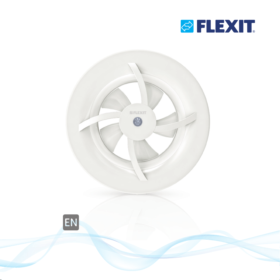
Pro7
115461EN-01
2016-02
Type: K7
Bathroom fan and Heat mover
Operating and installation instructions
Page 2
Important
Read these instructions carefully before use.
The fan is designed for permanent installation and must be installed by a qualified electrician.
Under standard EN 60335, the following must be observed. This device may be used by persons
from eight years upwards and by persons with reduced physical or mental capacity or who lack
experience and knowledge, providing they have received guidance or been instructed in the safe
use of the device and understand the risks involved. Children must not be allowed to play with the
device. Cleaning and maintenance must not be carried out by unsupervised children.
The package contains of:
1 pc Pro7 bathroom fan
3 pcs Screws for fixing the wall frame to the wall or ceiling
1 pc Mini screwdriver for changing the position of the multi-function selector
1 pc Set of operating and installation instructions
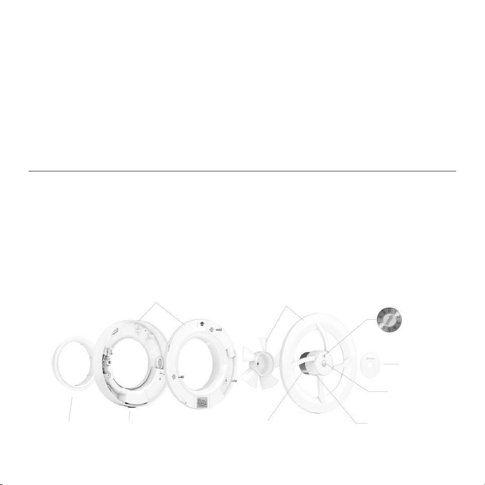
Fan parts
Wall frame with cover
with integral gaskets.
Motor unit with bayonet mount and
removable impeller. Easy to disassemble and
clean.
Multi-function
selector.
Spigot for duct
connection Ø100 mm.
Integrated
all-pole switch.
Self-calibrating motor
guarantees correct flow.
2
Twistable
cover.
Presence sensor.
Motion and light.
Self-adjusting humidity control
thermostat.
Page 3

Thank you for choosing a quality product from Flexit!
We hope you will be fully satisfied with your new Pro7 fan for many years to come. For your safety,
every product has been individually function-tested before leaving our production facility.
Pro7 - seven fans in one
Pro7 is a multi-function fan, developed and manufactured in Sweden, for installation as a
bathroom fan (with six different ventilation options), or as an energy-saving heat transfer unit.
Its unique multi-function selector makes it easy to switch between functions. Just lift the cover.
Select a function. Ready to go!
Bathroom fan (with six optional ventilation solutions)
Pro7 has six different selectable operating functions, for performing air extraction in all homes
with natural ventilation. It has been designed and approved for installation in wet rooms (IP44)
such as WCs, bathrooms and utility rooms. For mounting on wall or in ceiling. Ducting (Ø100125 mm), outer louvre/grille/cowl/back draught shutter are delivered separately. See Flexit
accessories.
Heat Mover – save energy
Pro7 has an integral electronic thermostat allowing the fan to transfer surplus heat from, e.g. a
fireplace, to an adjacent room. The fan is mounted on a partition wall or between floors
(wall/floor penetrations Ø100-125 mm).
Supply air
For good home ventilation you need to ensure that:
– air can reach the wet room e.g. via a gap in the door or a throgh a ventilation valve.
– fresh air enters the home via ventilation valves in bedrooms and living rooms.
3
Page 4
Installation
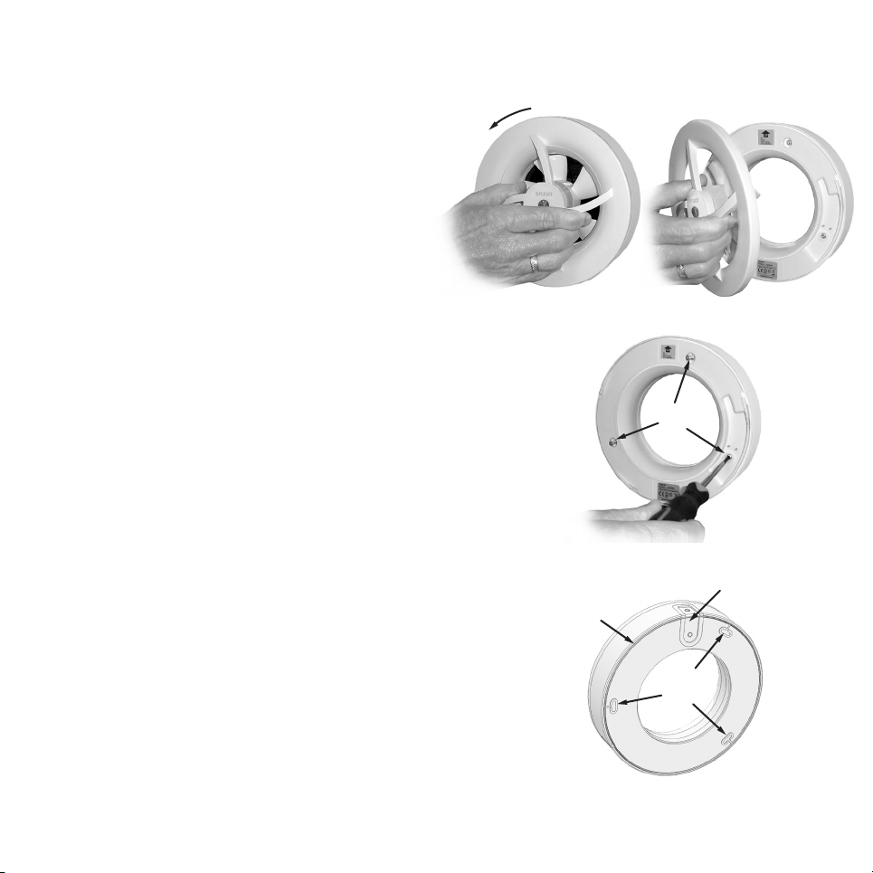
1. Preparations
1a
The motor unit has a unique bayonet
connection for ease of removal and
replacement in case of installation, change
of function and cleaning.
a) Lift the motor unit out of the wall frame.
Lightly grasp the spokes
and turn anti-clockwise.
b) The wall frame cover is retained by 3 screws.
Untighten these and remove the cover.
The screws will be retained by their gaskets and
do not need to be fully unscrewed.
2. Gaskets
To avoid water penetrating the fan, the wall frame has several
integral gaskets:
a) on the rear, gasket against the substrate.
b) by the cable bushing.
c) by the screw bushing, 3 in total.
If necessary, seal with silicone, etc.
Note: The fan is surface-mounted on walls or ceilings.
Seal any gaps between fan and ventilation duct.
1b
2
a)
b)
c)
4
Page 5
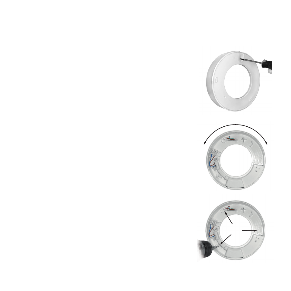
3. Mounting the wall frame
The fan is mounted on the surface on walls or in ceilings. Suitable
for Ø100 mm duct, but Ø125 mm can also be used.
a) The cable bushing is situated in the top part of the wall frame.
Electrical connection can either be performed from the rear
(concealed) or from the top (external), see also fig. 2b
Make a hole in the gasket with a pricker or similar sharp tool.
3a
b) Position the wall frame so that the cable bushing
is uppermost +/-45°.
c) Screw the wall frame to the substrate with the screws provided
(3 in total).
Use the Cover Plate accessory, art. no. 115463, if there is not
enough space for screw fixing.
5
3b
+45°-45°
3c
3 stk.
Page 6
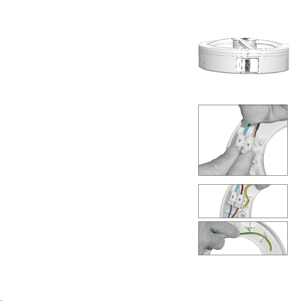
4. All-pole switch
According to standard EN 60335-1, it must be possible to
disconnect the fan from the mains supply. This requirement is
fulfilled with the integral all-pole switch (2-pole, 3 mm contact
gap).
4
5. Electrical connection
NB! May only be carried out by qualified electrician.
During any electrical work on the fan, the voltage supply must
be disconnected.
The fan is designed for permanent installation at 230 VAC,
50 Hz.
Double-insulated, requires no earth.
a) Connect in phase and neutral on terminal board.
Earth cable can be attacted two places:
b) to the right of the terminal board.
c) to the right of the cable bushing.
6
5a
5b
5c
Page 7
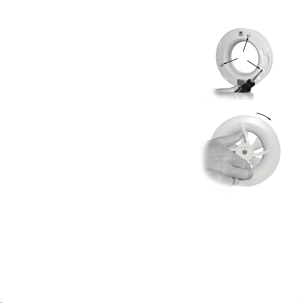
6. Reassemble cover and motor unit
a) Reassemble the cover on the wall frame (three screws).
Be sure that the two 12V pins are in the correct position
(rating plate downwards, arrow upwards)
6a
b) Reassemble and lock the motor unit in the wall frame by
turning it clockwise. To locate the correct position for the
bayonet mount, the multi-function selector must be in
position 12 noon.
There are also two lines on the bottom edge by the
all-pole switch which is lined up when the motor unit is
correctly mounted, see fig. 4.
7
6b
Page 8

Function description
Continuous basic ventilation (basic airflow)
The fan operates at a constant low speed, 40 m3/h, creating a useful basic ventilation.
Presence sensor – motion (IR) and light
The presence sensor is activated by motion (IR) or when the lighting is switched on. Delay time 15
minutes.
The fan switches to a medium speed, 60 m3/h, and depending on the choice of function, it starts up:
– directly (positions 1, 2 and 6)
– after a 2.5 minute delay (position 4)
Automatic humidity control
A self-adjusting humidity sensor continuously meassures the humidity level in the air. The fan
starts up automatically if the humidity level rises rapidly (e.g. in the case of a shower) or if the
relative humidity (RH) exceeds 70%. When the humidity level recedes, the fan returns to basic
airflow or stops.
Depending on the choice of function (see next page), the fan will operate at:
– High speed 95 m3/h (positions 1, 3, 4 and 6)
– Maximum speed 110 m3/h (position 2)
Manual start and stop by use of a switch
The fan may be connected for manual start via a separate light/power switch. When the switch is
activated, the fan will start up and run at high speed, 95 m3/h. When the switch is turned off, the
fan will stop.
Airing function
If the humidity control or presence sensor has not been active for 24 hours, the airing function
will start up. The fan will operate at medium speed (60 m3/h) for 30 minutes every 12 hours.
Heat Mover, thermostat
The fan will start at 28°C and move the surplus heat to adjacent rooms.
The fan turns off at 24°C. Airflow 95 m3/h.
8
Page 9
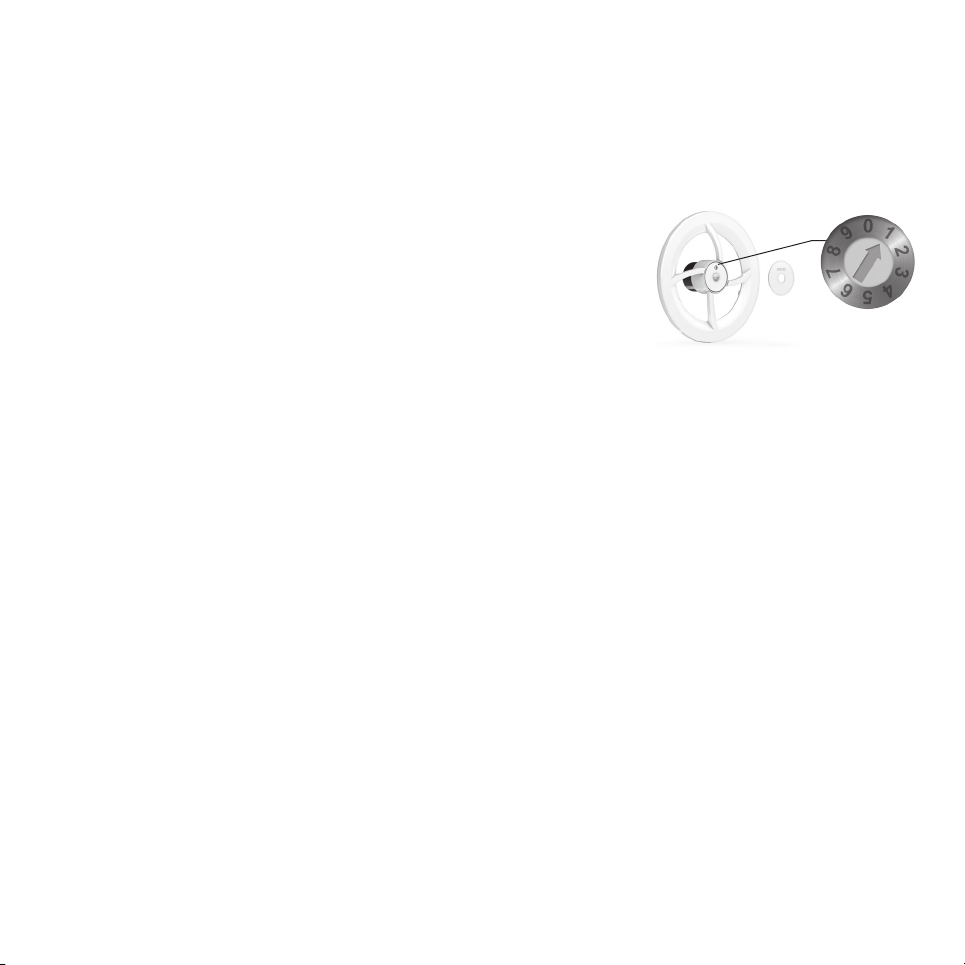
Function positions 1 - 7
Pro7 has seven function options. The fan is set to Position 1 at the factory, which means that it
will automatically function at three speeds, see function description below.
Changing the function
The unique multi-function selector makes it easy to switch
between functions. Lift the cover and select the desired function
manually with the accompanying screwdriver. Ready to go!
Note that it is possible to change function even when the motor
unit has been removed from the wall frame.
Position for continuous basic ventilation
Position 1 Fully automatic, three speeds:
Basic flow – low speed 40 m3/h
Presence sensor – medium speed 60 m3/h
Humidity control – high speed 95 m3/h
Position 2 As for position 1, but humidity control is set to max speed 110 m3/h.
Position 3 As for position 1, but without presence sensor operating.
Positions for occasional ventilation needs
Position 4 Autostart in case of presence or rising humidity levels in the room, 95 m3/h.
Position 5 Manual start/stop via switch. The fan will run at high speed, 95 m3/h.
Position 6 Airing function. If the fan has been inactive for more than 24 hours, it will start up
automatically and air the property, 60 m3/h. Otherwise, as for position 4.
Heat Mover
Position 7 Heat transfer unit, thermostat, 95 m3/h.
Positions 0, 8 and 9 are not used.
9
Page 10

Cleaning
To maintain its function and capacity, the fan must be cleaned at least twice a year, or more often if
necessary. No solvents may be used on the fan. The fan must not be submerged in or flushed with
water.
– Prior to cleaning: Turn off power to the fan with the integral all-pole switch.
– Lift the motor unit out of the wall frame (see fig. 1 in the Installation section).
– Clean the opening, duct and motor unit with a damp cloth
(if necessary a mild detergent may be used).
– The blade may be cleaned as situated. If the blade is very soiled, you can release it by pulling
it straight out. It can then be washed and rinsed.
– Mount and lock the motor unit in the wall frame (see fig. 6b in the Installation section).
10
Page 11
Environmental Product Declaration
The product and manufacturing complies with current international environmental
regulations such as WEEE and RoHS directive.
EE-products (Electrical and Electronic products)
In compliance with the WEEE directive Flexit is connected to the national system for
recycling of EE-products.
The symbol on the product shows that this product must not be treated as
household waste. It must be taken to a reception station for recycling of electric
and electronic equipment. By ensuring the correct disposal of the equipment,
you will contribute to preventing the negative consequences for the environment
and health that incorrect handling may entail. For further information on recycling of this
product, please contact your local authority, your waste disposal company or the company
from which you purchased it.
Warranty claims on this product are accepted in accordance with the applicable terms of sale,
provided that the product is correctly installed, used and maintained.
11
Page 12
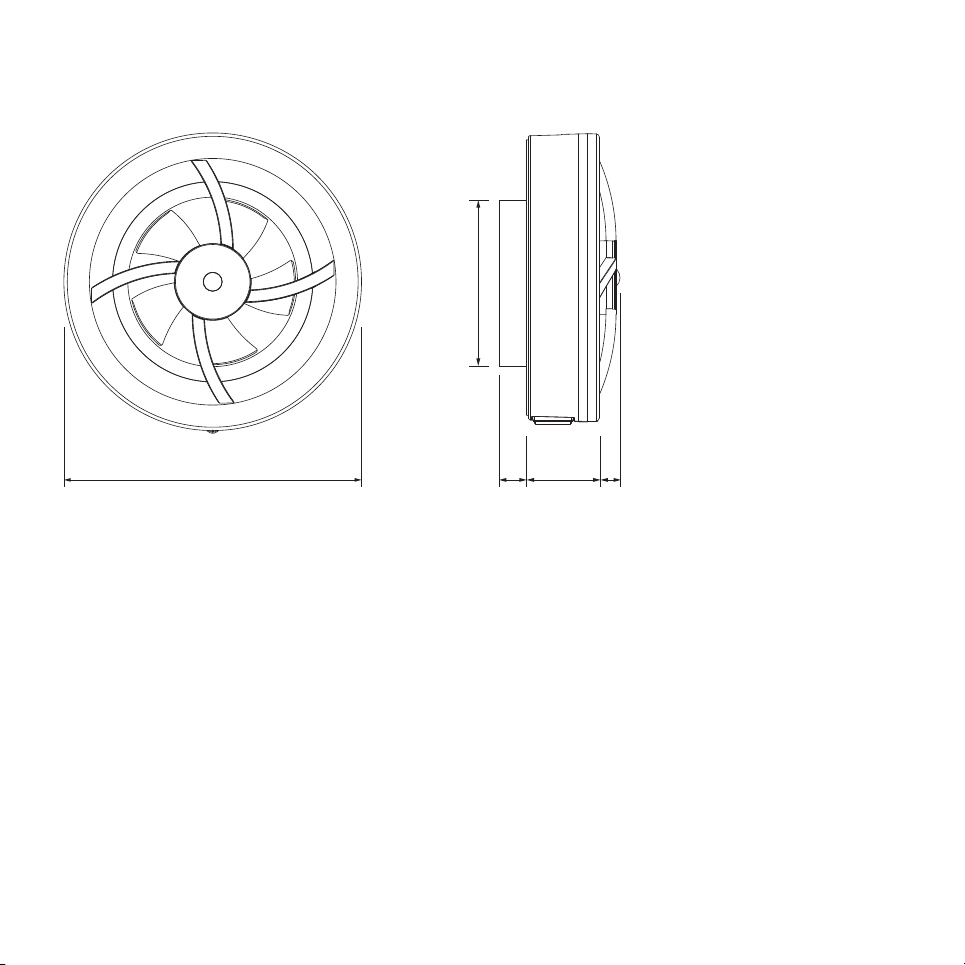
Dimensions
Ø 99
Ø 175
12
25
45 10
Page 13

Technical data
Voltage / frequency 230 V / 50 Hz
Power consumption 3 W
Protection rating IP 44
Insulation class Class II
Airflow:
Minimum speed 40 m3/h
Medium speed 60 m3/h
High speed 95 m3/h
Max speed 110 m3/h
Max pressure 48 Pa
Sound pressure 17-25 dB(A) 3m
Weight 0,48 Kg
Ambient temperature 5 - 35°C
Duct Ø100/125
Placement Wall and ceiling
Material Polypropen
Colour RAL 9016
13
Page 14
EC Declaration of Conformity
This declaration confirms that the product meet the requirements in the following directives
and standards
2006/95/EF Low-voltage Directive (LVD)
2004/108/EF Electromagnetic Compatibility (EMC)
2011/65/EU RoHS directiv
:
Manufacturer
: Nordiska Klimatfabriken AB, Fogdö Solö, 645 92 Strängnäs, Sweden
Type: K7 (Pro7, art.no. 115462)
Conformity with following standards, certificates and reports:
Standard Certificate Test report
EN 60335-1 : 2012 + A11 Intertek Semko 1510297 Intertek Semko 1510297STO-001
EN 60335-2-80 : 2003 + A1 + A2 Intertek Semko 1510297 Intertek Semko 1510297STO-001
EN 62233 : 2008 Intertek Semko 1510297 Intertek Semko 1510297STO-001
EN 55014-1 : 2006 + A1 : 2009 + A2 : 2011 Intertek Semko 1510653V Intertek Semko 1510653STO-001, Ed. 1
EN 55014-2 : 1997 + A1 : 2001 + A2 : 2008 Intertek Semko 1510653V Intertek Semko 1510653STO-001, Ed. 1
EN 61000-3-2 : 2014 Intertek Semko 1510653V Intertek Semko 1510653STO-001, Ed. 1
EN 61000-3-3 : 2013 Intertek Semko 1510653V Intertek Semko 1510653STO-001, Ed. 1
Frank Petersen
CEO
14
Page 15

15
Page 16

Flexit AS, Televeien 15, 1870 Ørje, Norway
www.flexit.no
 Loading...