

Page 1
User manual
Air handling unit with kitchen hood
Spirit K2
111139E-05
2013-12
Page 2

2
Contents
1 Functional Description 4
1.1 Heating element 4
1.2 Operation of kitchen hood 4
2 Cleaning/Maintenance 5
CI60 simple control unit
3 CI60 control unit overview 8
4 CI60 in use 9
4.1 General 9
4.2 Increasing/reducing air supply 9
4.3 Adjusting the air supply 9
4.4 Temperature adjustment 9
4.5 Filter replacement 9
4.6 Alarm 9
4.7 Reset 9
CI60 advanced control unit
5 CI600 control unit overview 10
6 CI600 in use 11
6.1 General 11
6.2 Idle mode 11
6.3 Menu navigation 11
6.4 Start menu 11
6.5 Operating status 11
7 CI600 main menu 12
7.1 Fan speeds 12
7.2 Max. timer 12
7.3 Settings 12
7.4 Temperature 12
7.5 Timer 13
7.6 Daily/weekly timer 13
7.7 Time and date 14
7.8 Language 14
7.9 Filter 14
7.10 Alarm 14
7.11 Operating information 14
8 CI600 advanced user menu 15
8.1 PIN 15
8.2 Advanced user 15
8.3 Temperature regulation 15
8.4 Configuration 17
8.5 Operating time 18
9 Maintenance table 19
10 Troubleshooting 20
11 EC Declaration of Conformity 21
Page 3

3
It is the installer's responsibility to carry out a full safety and function assessment of the appliance
To reduce the risk of fire, electric shock or injury, read all the safety instructions and warning texts before
using the appliance.
• This unit is only designed for ventilation air in buildings.
• It must not be used to extract combustible or flammable gases.
• Remove the power plug before commencing any service and maintenance work.
• Before opening the door, current to the unit must be turned off and the fans must have had time to stop (min. 3 mins.).
• The unit contains heating element which must not be touched when it is hot.
• The unit must not be operated without the filters being in place.
• Do not cook substances which could catch fire under the ventilator.
• Do not leave a saucepan or frying pan containing oil or grease unsupervised.
• Follow the instructions in the user manual.
To maintain good indoor air quality, comply with regulations and to avoid condensation damage the unit must never be stopped
apart from during service/maintenance or in connection with an accident.
Important Safety Instructions:
!
According to IEC/EN 60335-1
Note that the product is not designed for operation by person with
impaired physical, motor or mental abilities. The product must also not
be used by persons who lack experience or knowledge, unless they have
received guidance or instructions in operating the product safely by a
person responsible for safety.
Our products are subject to continuous development and we therefore reserve the right to make changes.
We also disclaim liability for any printing errors that may occur.
EXAMPLE OF NIPPLE LOCATION
(shown as right-hand model)
HIGH VOLTAGE
DANGER! DO NOT TOUCH
Symbols Used
These products bear a number of symbols used for
labelling the actual product and in installation and user
documentation.
NB! When a text bears this symbol, damage to
equipment or a poor utilisation ratio may result if
instructions are not followed.
CAUTION When a text bears this symbol, it
means that personal injury or serious damage to
the equipment may result if the instructions are
not followed.
!
SAFETY SWITCH
Page 4

4
1 Functional Description
See page 19 for component description.
Cold outdoor air passes through one half of the rotor
(HR-R), while warm extract air passes through the other half,
without the two mixing. Using this principle, a large proportion
of the heat in the extract air is transferred to the supply air the heat store principle (see system sketches). If the outdoor
temperature is extremely low, a thermostat-controlled
heating element (EB1) also ensures that the supply air has
the desired temperature. This supply air is passed via ducts
and valves to living rooms and bedrooms. The extract air
is extracted either from the same room or via door gaps/
overflow gratings to toilets and wet rooms. The used air is
passed via a duct system back to the unit, gives off its heat
and is expelled from the building via a roof cowl, combi-box
or wall grating.
When there is no need for heat recovery (for example in the
summer), the rotor stops.
1.1 Heating element
The heating element is protected against overheating by
the thermostat (F20), which switches off at 60°C. As an
additional safety measure, the thermostat (F10) switches
off at 85°C. Thermostat F10 needs to be reset manually by
pressing the reset button.
You will find the thermostat by opening the unit doors
(located directly over the heating element).
1.2 Operation of kitchen hood
A - Knob for damper and for forced ventilation
B - Pushbutton for light
When cooking, open the damper by turning damper switch A.
1) Turn the knob to level 1. The damper will be half open.
2) Turn the knob to level 2. The damper will be fully open.
3) Turn the knob to level 3 and the unit will increase the air
volume to speed 3 (forced ventilation).
4) You will need to turn the damper back manually (when
cooking is finished).
Fig. 1
This is purely a ventilation system and not a
heating system. The home must be heated in the
normal manner.
B
3
2
1
0
B
A
Page 5
5
2 Cleaning/Maintenance
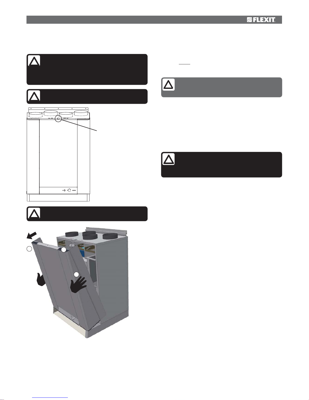
1. Hold the door by its upper edge, which has a recessed
grip.
2. Pull the door to release it from its catch.
3. Change your grip and lift the door off. NB! The door
weighs 10 kg.
Fans:
The fans must be cleaned once a year. Clean the fan
blades with a grease solvent on a cloth - or with brush
and compressed air if possible. NB! Do not use water.
Dismantle the fan as follows: Open the doors as
instructed.
EC fan: Release the screw at the front of the fan. Pull out
the electric quick-release contact for the motor. The fan
can now be pulled carefully down and out of the unit.
Filters:
To preserve a healthy indoor air quality, it is important to
change filters when they are dirty. Dirty filters lead to:
How often the filters need to be changed depends on
the degree of contamination of the air where they are
installed. In general, the filters need to be changed once
a year, preferably in the autumn (after the pollen season).
In areas with a lot of dust and contamination, the filters
should be changed in the spring and autumn. The supply
air filter and extract air filter consist of a compact filter
(F7). These are pushed into place.
It is recommended that you order a filter subscription
to ensure full benefit from the system and the cheapest
prices.
When changing the filter, check that the whole
unit is working normally.
Rotor:
As the unit has filters with a high impermeability class
installed, it is not usually necessary to clean the rotor.
If for various reasons it should still be necessary, dust
can be removed with a soft brush. Further cleaning is
possible if you remove the rotor, spray it with fat-soluble
detergent and then blow it clean from the opposite side.
Distance approximately 60mm and max. pressure 8,0
bar. Ensure that the motor is not exposed to water during
cleaning. Ensure that all seals around the rotor are intact
and tight.
External cleaning:
Many kitchen surface cleaners contain chemicals
that may damage the product’s plastic components.
Therefore use a soft cloth moistened with warm water and
a neutral detergent to clean the outside of the product.
Important! Do not use abrasive cleaners or scouring
powder, as they will damage the colour. Products that
give stainless steel an anti-fingerprint coating must not
be used either.
Before opening the door of the heat recovery
unit or carrying out maintenance on the kitchen
hood: switch off the heat, let the fans continue for three
minutes to remove hot air, disconnect power from the
unit and wait 2 minutes before opening the doors.
!
Increased air resistance in the filter – less air in
the home – risk of bacterial growth in the filter
– in the worst case scenario, the system can be
damaged.
!
Remember that the door is heavy (10 kg) when
lifting it off the unit.
!
1
2
3
Fig. 2
Remember first to remove the safety lock at the
top of the door.
!
safety lock
If the kitchen hood is used often, the extract air
fan must be checked and if necessary cleaned
every four to six months.
Page 6
6
Do not use detergent that is harmful to
aluminium or the environment.
Fig. 3
C
1
2
3
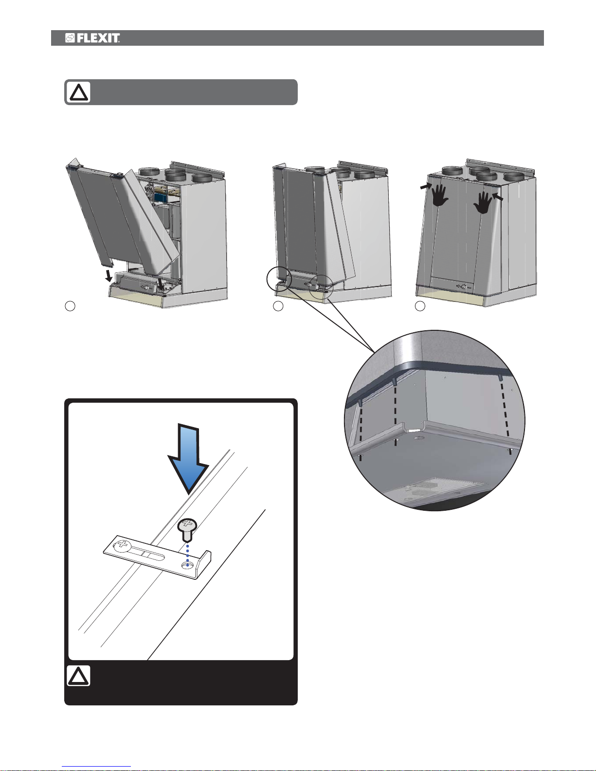
Mounting of door:
1. Lower the front edge of the door into the leading edge of
the unit.
2. The guide pins on the door must pass through the base of
the unit.
3. Push the top edge of the door to lock it.
CAUTION! For safety reasons, always mount the
door screw when you’re finished maintaining the
ventilation unit!
!
Page 7
7
Kitchen hood:
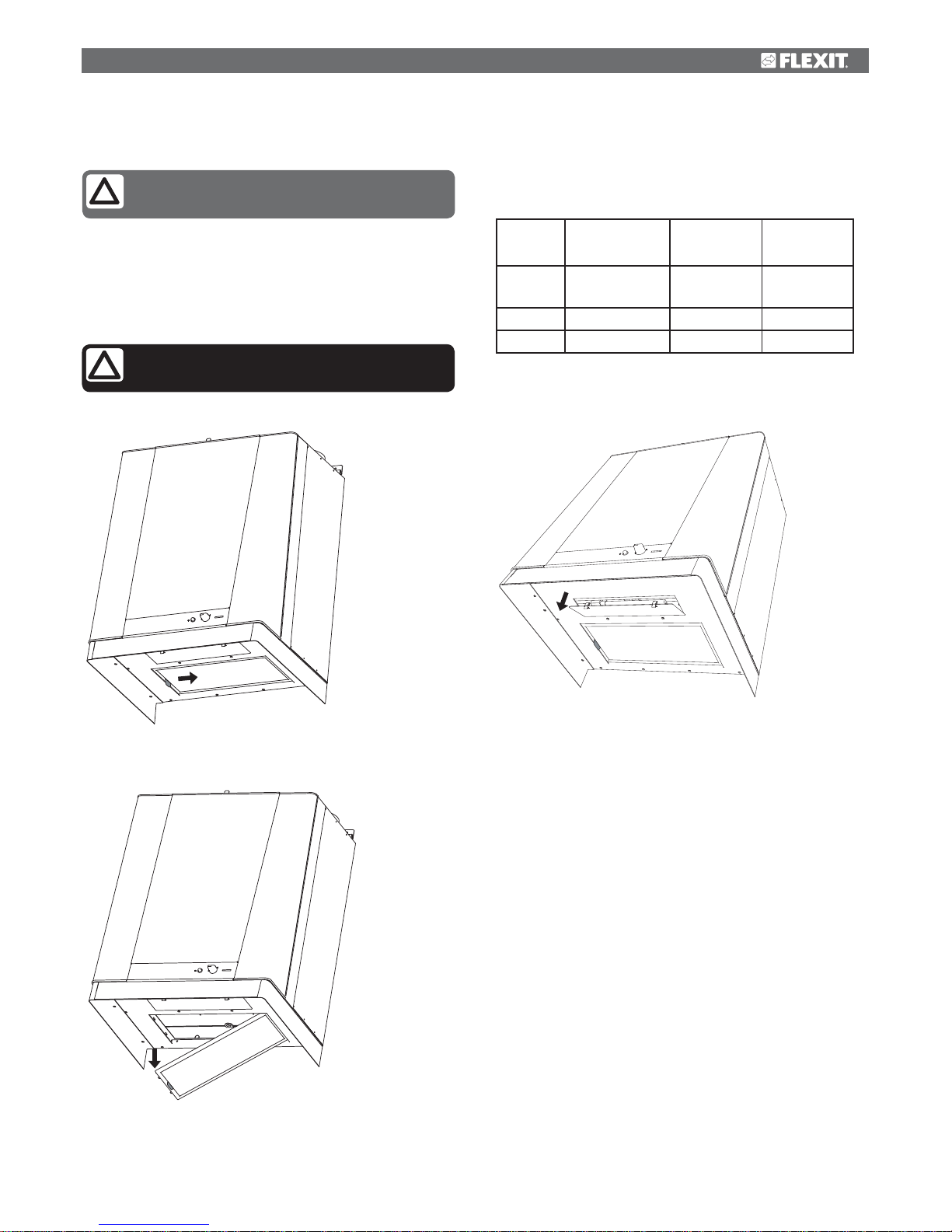
Wipe the volume hood with a damp cloth and detergent.
Dismount the filter (see figs. 4 and 5) and place it in hot
water with washing-up liquid. The filter cassette can also be
washed in the dishwasher. Several times a year the volume
hood should be cleaned internally. Wipe it internally with a
damp cloth and detergent. Replace the filter cassette and
press it up so that it fixes to the snap locks.
Fig. 5
Fig. 4
Fig. 6
To change the fluorescent tube, remove the lamp glass
by pressing the snap locks in the direction of the arrow,
Fig. 6.
The fluorescent tube can now be accessed for
replacement.
International
ILCOS code
Philips
designation
Osram
designation
Light
source
FSD-11-G23 PL-S 2-pin DULUX-S
Power 11W 11W 11W
Earth G23 G23 2-pin G23 2-pin
The filter must be cleaned roughly twice a
month with normal use.
The risk of fire increases if the volume hood is
not cleaned as often as specified.
!
Page 8
8
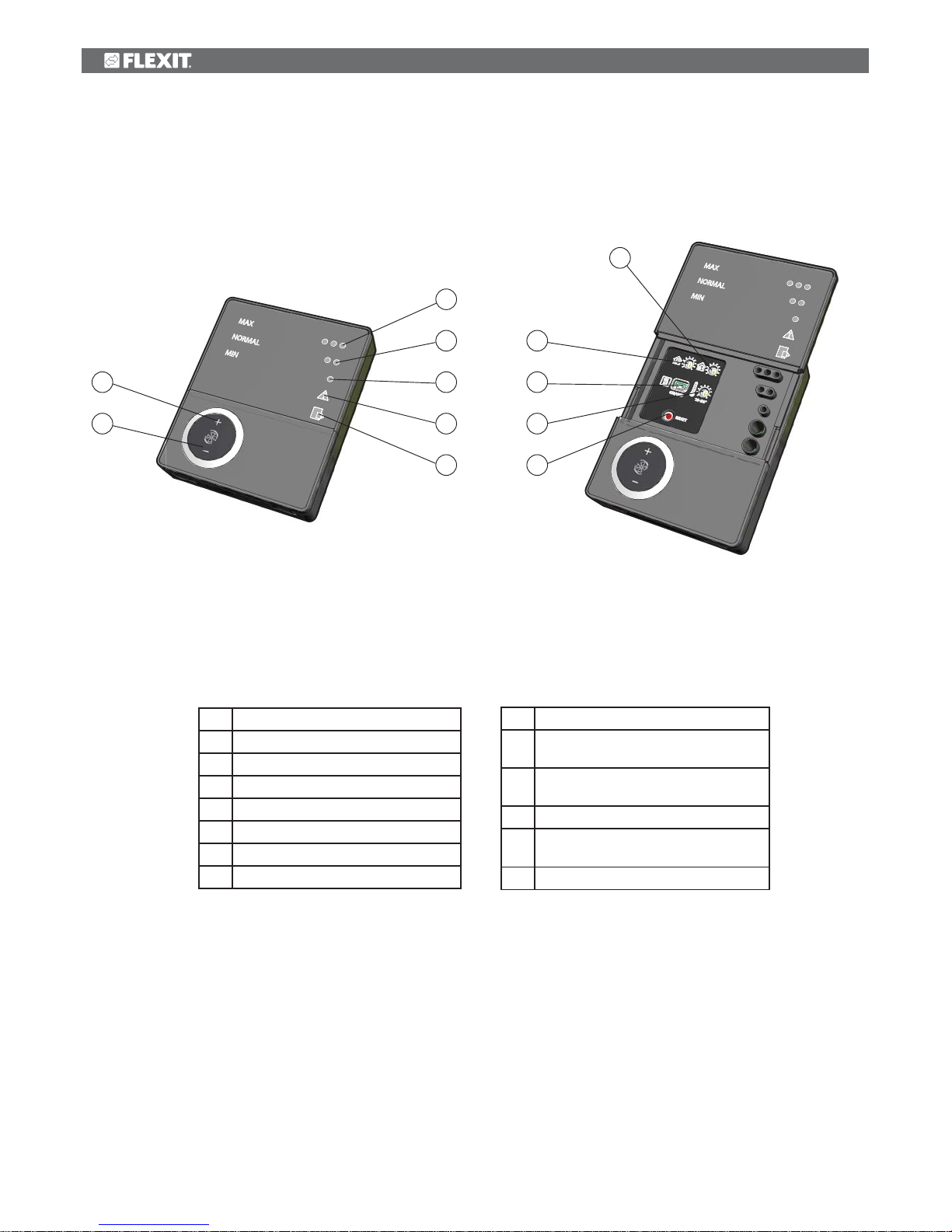
3 CI60 control unit overview
3
4
5
6
7
1
2
8
9
10
11
12
No. Description
1 Switch for increased ventilation
2 Switch for decreased ventilation
3
Indication of MAX speed
4
Indication of NORMAL speed
5
Indication of MIN speed
6
Indication of ALARM
7
Indication of FILTER REPLACEMENT
No. Description
8 Potentiometer for adjusting extract air
at NORMAL speed
9 Potentiometer for adjusting supply air at
NORMAL speed
10
Switch for additional heating OFF/ON
11 Potentiometer for adjusting supply air
temperature
12 Switch to reset the alarm
*The figures are used as references in subsequent descriptions
Page 9
9
4 CI60 in use
4.1 General
The control unit consists of a touch panel with pushbuttons,
LEDs for indication and adjustment potentiometers and
switches for adjusting the ventilation unit. The control unit
communicates with the ventilation unit via a low-voltage
cable.
4.2 Increasing/reducing air supply
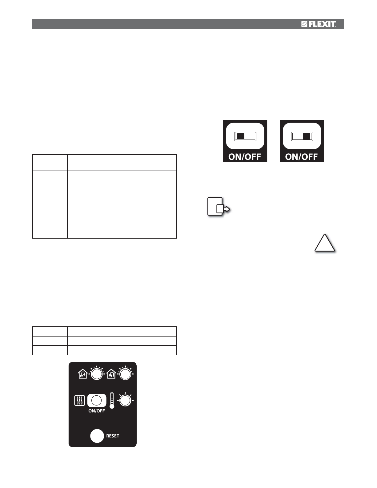
Use switches 1 and 2 to increase and reduce the fan speed
and thus the air flow. Different speeds depending on the
operating situation.
MIN
Do not use during first year of operation, or
when the building is in use.
NORMAL
Used under normal conditions. In this
setting, the air supply must be adjusted
according to current regulations.
MAX
Used if there is a need for increased air
supply on account of increased occupancy
or a higher humidity level, for example
during showering or when clothes are being
dried. This setting is usually used for limited
periods of time.
The different speeds are indicated with LEDs 3, 4 and 5.
4.3 Adjusting the air supply
At NORMAL speed level, the air flow must be adjusted
according to project data. Potentiometer 9 is used for the
supply air level and potentiometer 8 for the extract air level.
The adjustment range is 20-100% of the maximum level
according to the scale of the potentiometer.
Factory settings:
MIN
50% (fixed)
NORMAL
75% (variable)
MAX
100% (fixed)
4.4 Temperature adjustment
The temperature required in the supply air can be set with
potentiometer 11. The adjustment range is 10 - 30 °C.
Using the factory settings is recommended.
If necessary, the ventilation unit’s additional heating can
also be switched OFF/ON with switch 10.
4.5 Filter replacement
Every six months, LED 7 lights up to remind you that it is
time to replace the air filters in the unit. See section 3 for
more information on filter replacement.
4.6 Alarm
If anything unforeseen occurs with the
ventilation unit, indicator 6 lights up.
The signal given by the indicator depends on the reason
for the indication.
A permanent light indicates:
• Fault return water detector (B5)
• Heat recovery fault (B)
A permanent light with indicator 5 (MIN speed) flashing
indicates:
• Fault supply air detector (B1)
• Fault extract air detector (B3)
• Fault outdoor air detector (B4)
A flashing light indicates:
• Overheating thermostat fault (applies only to electric
heating)
• Fault in external fire/smoke detector (accessory)
• Heat recovery fault (A)
• Additional heating fault (applies only if the unit has a
water battery)
4.7 Reset
After the filter has been replaced or the cause of the
alarm repaired, the alarm must be reset. This is done by
pressing switch 12.
If the indicator goes out, the action has been carried out
correctly. If the indicator remains on, the fault has not
been repaired correctly.
After the activity has been carried out, the
indicator must be reset. See more under the
Reset section.
!
8
9
10 11
ON
OFF
ITEM 10
Page 10
10
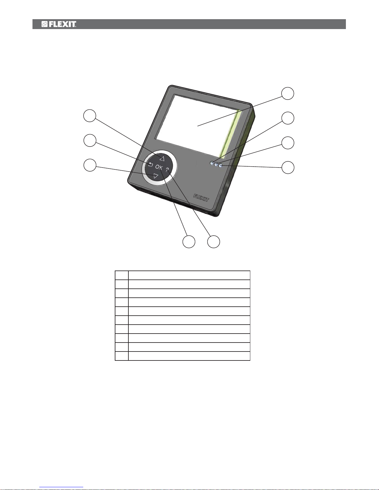
5 CI600 control unit overview
No. Description
1
UP/INCREASE switch
2
BACK/CANCEL/NO switch
3
DOWN/DECREASE switch
4
OK/YES switch
5
HELP switch
6 Display
7
Indication of OPERATION/OK - Green light
8
Indication of FILTER REPLACEMENT - Yellow light
9
Indication of ALARM - Red light
6
7
8
9
1
2
3
4 5
*The figures are used as references in subsequent descriptions
Page 11
11
If you select a function that has numerical values,
the current value is displayed with a light blue cursor.
The value is changed with buttons 1 and 3 and is then
confirmed by pressing button 4.
TIME AND DATE
13 : 45 04.07.09
45
040709
TIME DAY MONTH YEAR
OK?
If several values can be changed, the cursor jumps to
the right when a selection is confirmed with button 4. The
procedure is repeated until all values have been changed
to the desired values.
If you want to cancel a function or return to the previous
menu screen, use button 2.
Button 5 activates a help text that briefly describes the
current menu screen.
6.4 Start menu
When the system is started, a start menu is opened.
START MENU
LANGUAGE
TIME AND DATE
MAIN MENU
OK?
>
>
The basic language and date settings are set in this menu.
When this activity has been carried out, you choose to go
to the main menu.
6.5 Operating status
In normal operation without problems, the green LED 7
lights up to confirm that everything is working normally.
How any problems affect the system is described in
subsequent sections.
6 CI600 in use
6.1 General
The control unit consists of a colour display, a touch panel
and indicators (LEDs). The unit communicates with the
ventilation unit via a low-voltage cable.
6.2 Idle mode
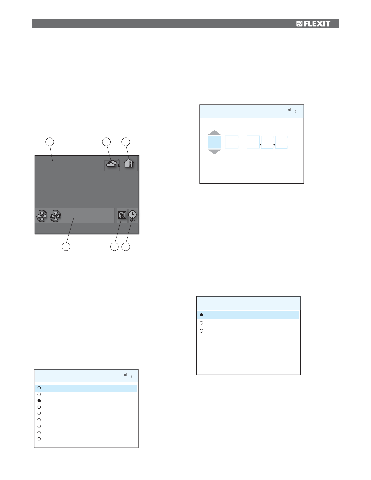
If the touch panel is not used, the control unit will, after a
certain period of time, enter idle mode, in which operating
information will be displayed.
13.08.2009
16:43
18°C 22°C
- NORMAL
A. Time and date
B. Outdoor air temperature
C. Room temperature
D. Current speed
E. Additional heating activated/deactivated
F. Daily/weekly timer active
6.3 Menu navigation
Buttons 1 and 3 are used to navigate through the menu lines.
The cursor is illustrated by the line being light blue. If it is
possible to make a selection on the current menu line, this
is displayed with OK? to the right of the line. A selection is
confirmed by pressing button 4.
If a menu line contains submenus, this is illustrated with a ‘>’
sign at the end of the line.
SETTINGS
TEMPERATURE
TIMER
DAY/WEEK SETTINGS
TIME AND DATE
LANGUAGE
FILTER
ALARM
ADVANCED USER
OPERATING INFORMATION
>
>
OK?
>
>
>
>
>
>
A
B C
D E F
Page 12
12
7 CI600 main menu
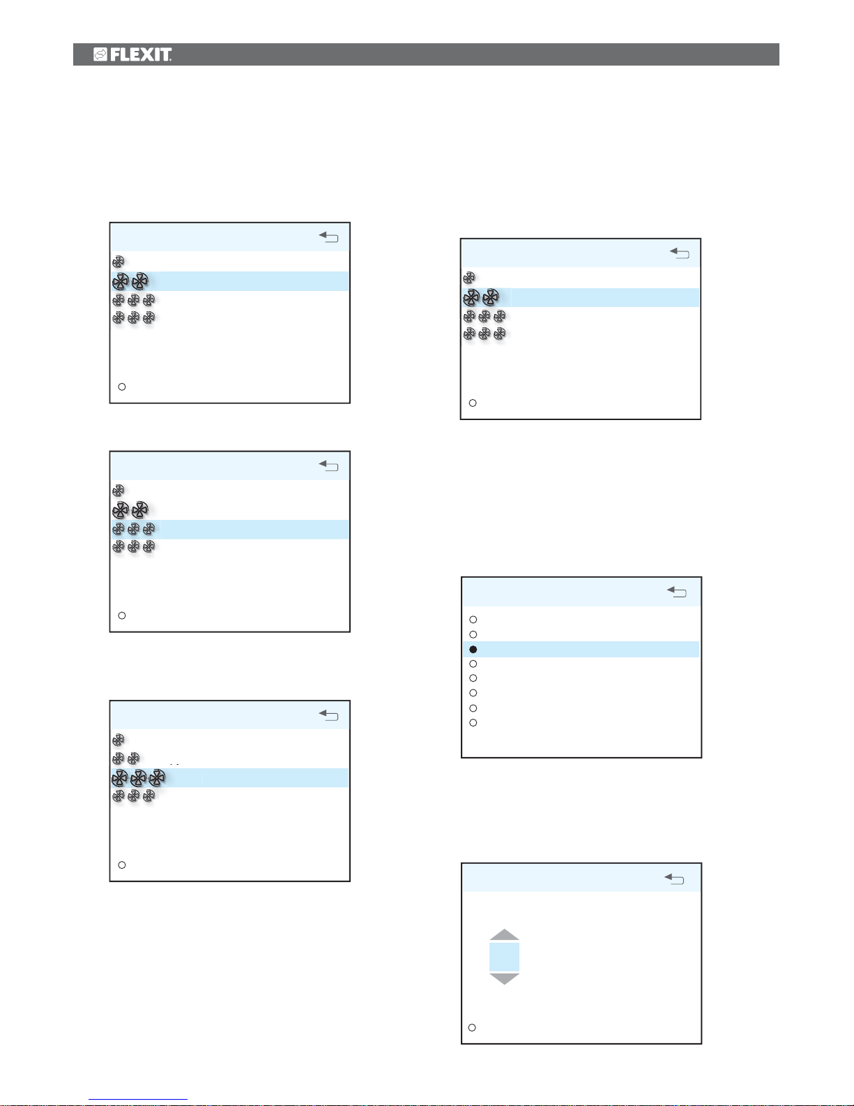
7.1 Fan speeds
The main menu contains various choices. Most concern
fan speeds. The speed selected is indicated with large fan
symbols and bold font.
MAIN MENU
SETTINGS
>
OK?
MIN
NORMAL
MAX
MAX TIMER
To change the speed, move the cursor with buttons 1 and 3.
MAIN MENU
SETTINGS
>
MIN
NORMAL
MAX
MAX TIMER
OK?
Then confirm your selection with button 4 and the speed
selected is highlighted with large fan symbols and bold font.
MAIN MENU
SETTINGS
>
MIN
NORMAL
MAX
MAX TIMER
OK?
7.2 Max. timer
This menu item activates a function that increases the speed
to MAX for a limited period of time before subsequently
returning to the speed selected previously. The period of
time can be adjusted under the SETTINGS menu item.
MAIN MENU
SETTINGS
>
OK?
MIN
NORMAL
MAX
MAX TIMER
When the function is active, the time is counted down on the
display. If you select TIMER OFF, the function will be cancelled
and the speed will return to the previous selection.
7.3 Settings
Under the SETTINGS menu item, you can adapt the system
as you want.
SETTINGS
TEMPERATURE
TIMER
DAY/WEEK SETTINGS
TIME AND DATE
LANGUAGE
FILTER
ALARM
ADVANCED USER
>
>
OK?
>
>
>
>
>
7.4 Temperature
Here you set the temperature for the air that enters the
building.
TEMPERATURE
18
OK?
HEATING ELEMENT ON/OFF
°C
>
Page 13
13
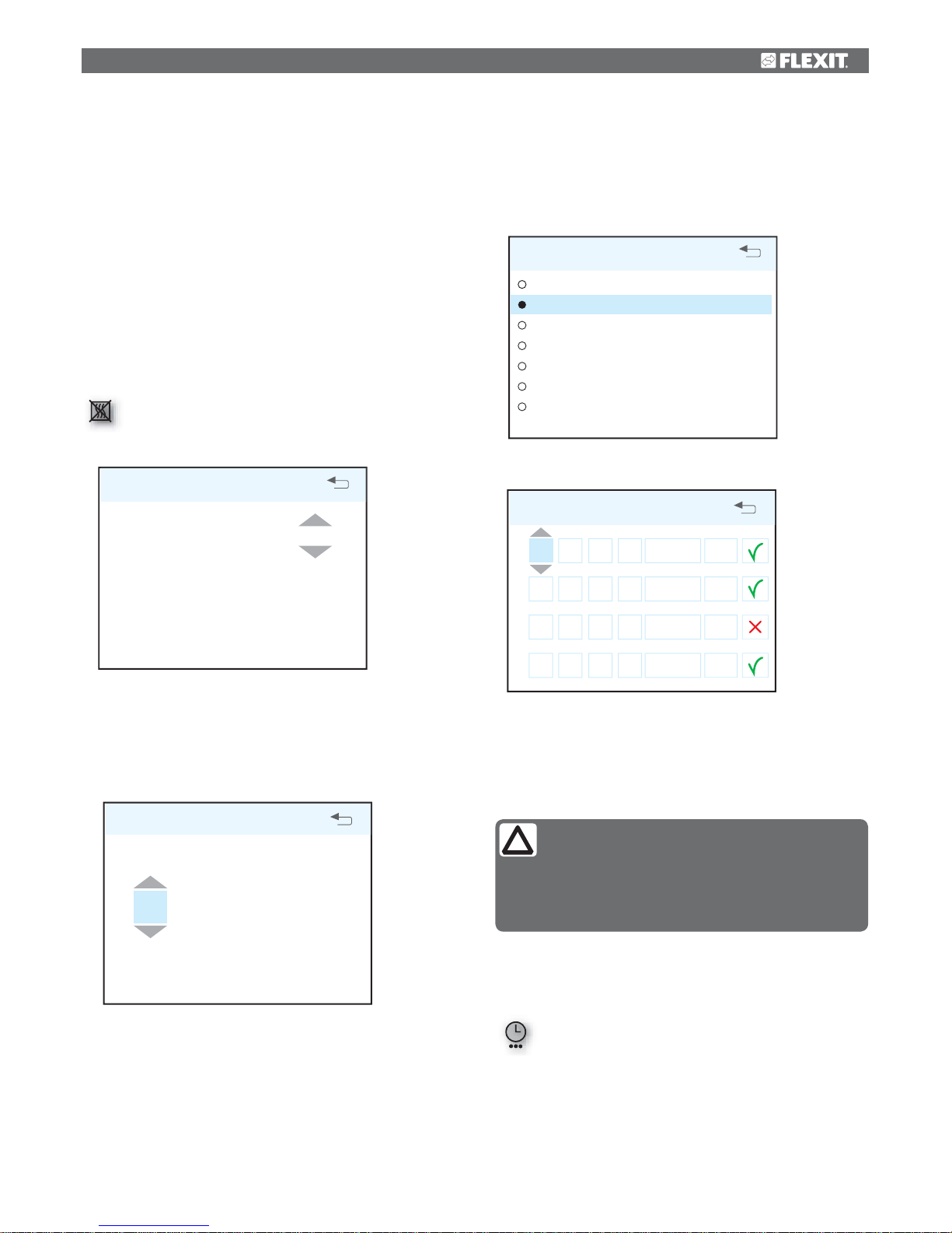
7.6 Daily/weekly timer
The programming of the timer begins by selecting the
day.
DAY / WEEK SETTINGS
MONDAY
TUESDAY
WEDNESDAY
THURSDAY
FRIDAY
SATURDAY
SUNDAY
OK?
A new menu screen appears under each day.
TUESDAY
1 08
:
00
16
:
00
-
MIN
16°
2 16
:
00
18
:
00
-
NORMAL
18°
3 18
:
00
19
:
00
-
MAX
16°
4 19
:
00
24
:
00
-
NORMAL
18°
Each day can be programmed with four different time
intervals. Adjust the start and stop times for each interval
and then adjust the desired speed and temperature.
To activate the interval, select a green tick. A red cross
means that the interval is not activated. If necessary, then
select another interval and repeat the procedure.
After you have finished programming a day, repeat the
procedure for other days.
When the timer is active, this symbol is displayed
when the display enters idle mode.
If there is no new time interval registered after the finished
period, the speed and temperature return to the setting
that was previously active.
We recommend adjusting the temperature to max 18° so
that the air is mixed optimally with the air already in the
building.
In the HEATING ELEMENT OFF/ON menu item, the additional
heating in the ventilation unit can be switched off. In such
case, only the rotating heat exchanger is used as a source of
heat.
NB! This is not possible if the unit is installed with a water
battery.
HEATING ELEMENT ON/OFF
HEATING ELEMENT ON
OK?
7.5 Timer
Here you set the time you want for the MAX TIMER function.
This is used when the function is activated from the main
menu.
TIMER
60
min
OK?
If the heating element is switched off, this
symbol is displayed when the display enters idle
mode.
NB!
The following rules apply to the programming:
• A time interval with a higher number can never
be started before a previous one has been finished.
• The stop time can never appear before the start
time.
Page 14
14
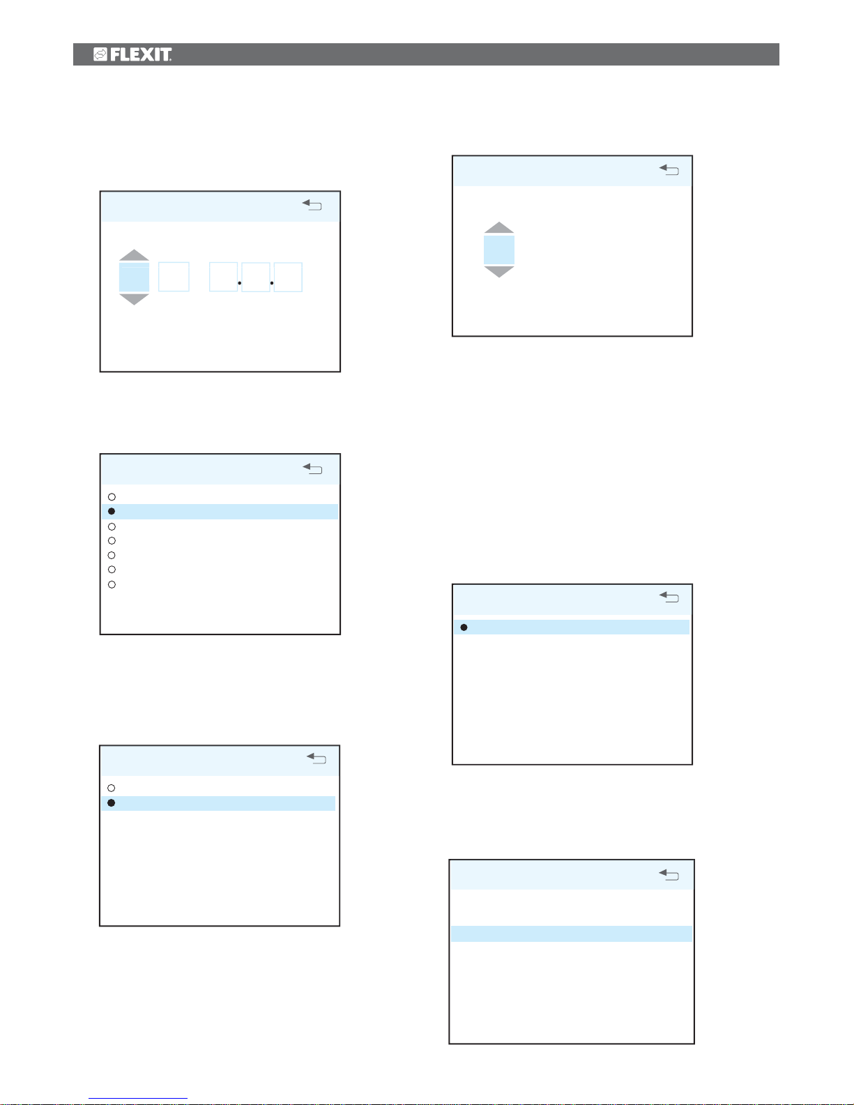
7.7 Time and date
The time and date can be adjusted in this dialog.
TIME AND DATE
13 : 45 04.07.09
45
040709
TIME DAY MONTH YEAR
OK?
7.8 Language
The language selected can be changed in this dialog.
LANGUAGE
NORSK
ENGLISH
SVENSKA
DEUTCH
NEDERLANDS
SUOMI
DANSK
OK?
7.9 Filter
A reminder appears regularly in the display. In this dialog, the
time interval can be adjusted and the filter alarm reset.
FILTER
INTERVAL CHANGE OF FILTER
RESET FILTER ALARM
>
OK?
INTERVAL CHANGE OF FILTER
6 MND
OK?
The normal time is 6 - 12 months, depending on the
environment.
When the filter alarm is triggered, the yellow indicator 8 lights
up and an information text appears. Follow the instructions
in the text. It is possible to go directly to this dialog from
the message or via the menu tree. After the alarm has been
reset, the countdown to the next filter replacement begins.
7.10 Alarm
If a problem occurs in the operation of the ventilation unit,
an alarm will be triggered. The red indicator 9 lights up
and an information text appears in the display. Follow the
instructions in the text. It is possible to go directly to this
dialog from the message or via the menu tree.
ALARM
RESET ALARM
OK?
7.11 Operating information
This general screen displays current temperature values,
whether the daily/weekly timer is active and activity as
0-100% for cooling, heat exchanger and additional heating.
OPERATING INFORMATION
SET TEMPERATURE
DAY / WEEK SETTINGS
SUPPLY AIR
EXTRACT AIR
OUTDOOR AIR
RETURN WATER
HEAT RECOVERY SYSTEM
COOLING
HEATING
22°
AKTIV
22°
21°
0°
35°
100%
0%
100%
Page 15
15
8 CI600 advanced user menu
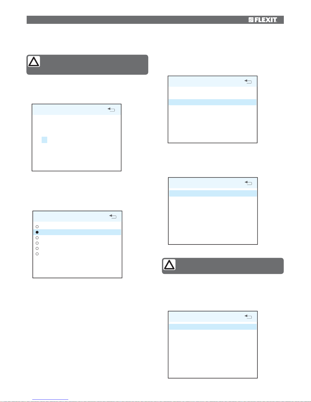
8.1 PIN
To access the menu item, you need to enter the PIN 1 0 0 0.
PIN CODE
OK?
1 0 0 0
8.2 Advanced user
This menu contains functions for monitoring, configuration
and troubleshooting.
ADVANCED USER
TEMPERATURE REGULATION
FAN REGULATION
CONFIGURATION
OPERATING TIME
FACTORY SETTINGS
SERVICE
>
OK?
>
>
>
>
8.3 Temperature regulation
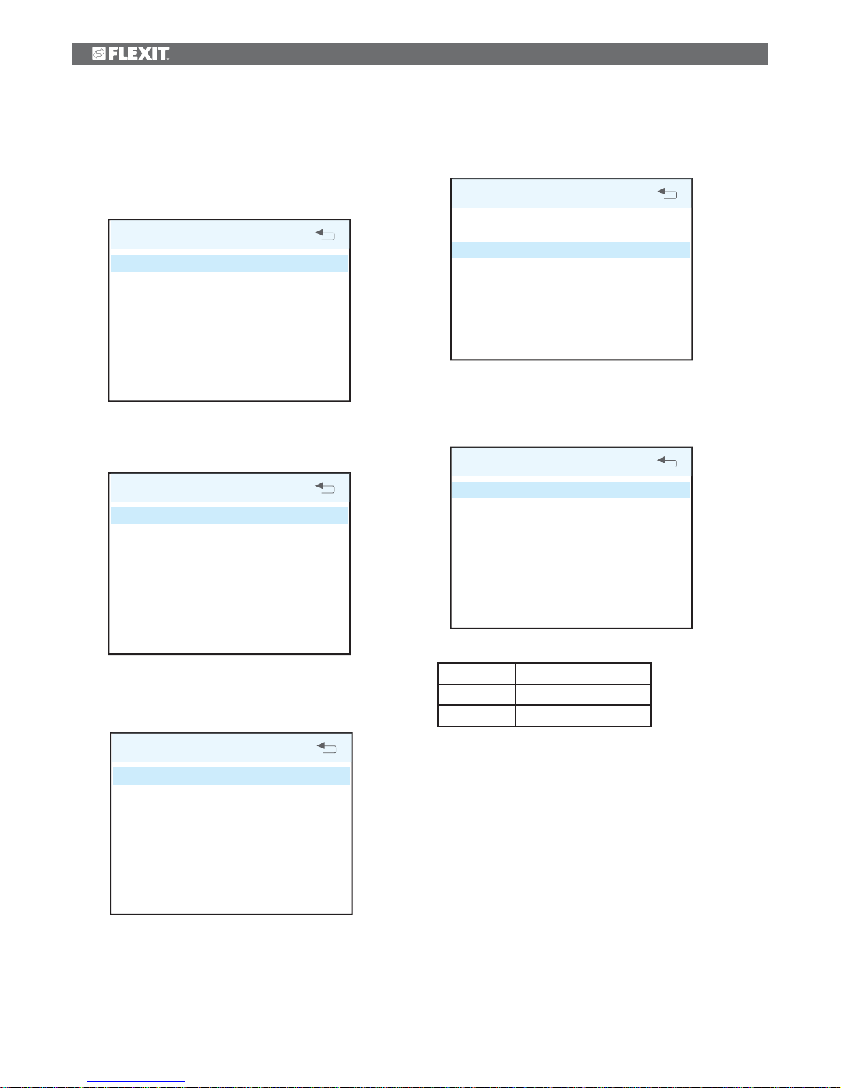
In this menu screen, you configure the temperature
regulation and cooling functions.
TEMPERATURE REGULATION
REGULATION T YPE
COOLING
NEUTRAL ZONE
EXT. TEMP. CONTROL
>
>
OK?
>
Regulation type
If supply air regulation is selected, no further settings can
be set here. If extract air regulation is selected, the max.
and min. supply air temperatures can also be specified.
REGULATION TYPE
REGULATION
MAX SUPPLY AIR TEMP
MIN SUPPLY AIR TEMP
EXTR OK?
35°
15°
Cooling
In this dialog, the cooling function is activated and
the parameters MIN OUTDOOR AIR TEMP for supply
of cooling and MIN SPEED for supply of cooling are
specified. If a DX cooling machine is used, the supply
delay interval can be specified.
COOLING
COOLING
MIN OUTDOOR TEMP
MIN SPEED
RESTART DELAY
COOLNESS RECOVERY
OK?
>
AV
18°
MIN
180 s
NB! Flexit does not supply or project cooling
machines.
NB! For more information on the ”Advanced
User” menu, refer to the ”CI600 Reference Manual” on Flexit’s homepage.
Page 16
16
It is also possible to activate a function to recover
cooling in the building using the rotating heat exchanger.
Enter the desired difference between the outdoor
and indoor air temperatures for when the function is
activated.
COOLNESS RECOVERY
COOLNESS RECOVERY
DIFF
OFF
1°
OK?
Neutral zones
To achieve more even temperature regulation, the
neutral zones can be set in this menu.
NEUTRAL ZONE
COOLNESS RECOVERY
HEAT RECOVERY SYSTEM
2°
1°
OK?
External temperature control
Control of the temperature settings from an overall
system must be entered in this menu. In this case, the
temperature settings in the control unit are overridden.
EXT. TEMP. CONTROL
EXT. TEMP. CONTROL
OFF
OK?
Fan control
The fans are selected and configured in this menu screen.
FAN REGULATION
SUPPLY AIR
EXTRACT AIR
TIMER
AIR VOLUME COMP
>
>
OK?
>
Adjustment (supply air and extract air)
This dialog is identical for the supply air and extract air fans.
The fans are adjusted individually to the desired capacity for
the respective speed.
SUPPLY AIR
MIN SPEED
NORMAL SPEED
MAX SPEED
OK?50%
75%
100%
Factory settings:
MIN
5V
NORMAL
7,5V
MAX
10V
Page 17
17
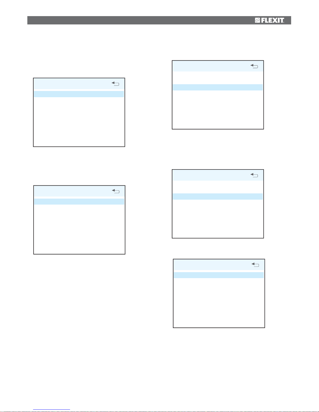
Timer
Settings are entered in this menu for the speed and time that
are to apply to the ‘MAX TIMER’ function in the main menu.
TIMER
STANDARD SPEED
STANDARD TIME
OK?MAX
30 m
Air flow rate compensation
This function can be activated via an input on the control
card. The speeds required for each fan are selected here. The
function can be used with a kitchen fan or other device that
requires additional supply air.
AIR VOLUME COMPENSATION
SUPPLY AIR
EXTRACT AIR
OK?MAX
MIN
8.4 Configuration
The general configuration is set in this menu screen.
CONFIGURATION
SENSORS
FIRE/SMOKE
COMMUNICATION
START/STOP SEQUENCE
REST MODE
>
>
OK?
>
>
Sensors
The temperature sensors can be calibrated in this menu
to be better coordinated with the real situation, and a
pressure sensor is activated as a pressure guard instead
of the integrated time control.
SENSORS
SUPPLY AIR
EXTRACT AIR
OUTDOOR AIR
RETURN WATER
FILTER GUARD
>
>
OK?
>
>
The menu screen is identical for all temperature sensors
and they can be adjusted within an interval of 5 °C.
SUPPLY AIR
CALIBRATION
OK?0
Page 18
18
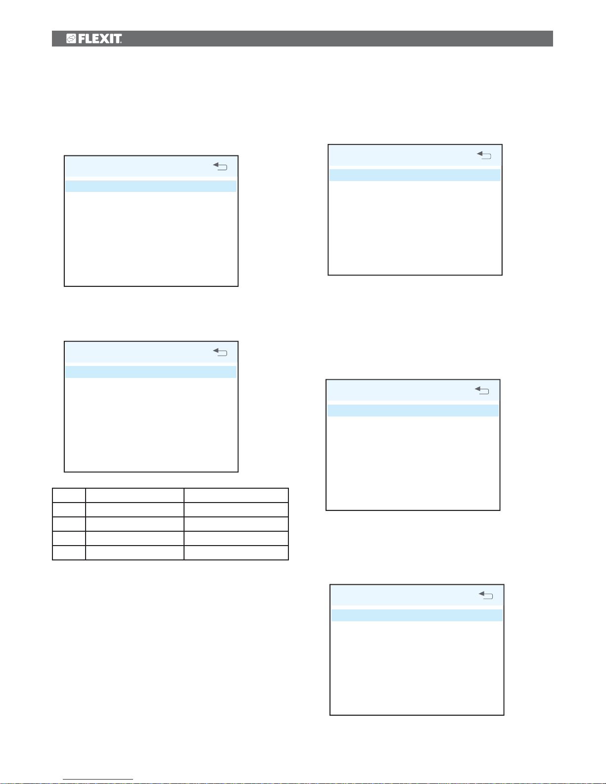
If the pressure guard is activated, an external sensor must
be connected to the control card. The sensor replaces the
integrated filter time control.
FILTER GUARD
ACTIVATION
OK?OFF
Fire/Smoke
This function requires an external sensor to be connected to
the control card.
FIRE/SMOKE
MODE
OK?1
Mode Supply air fan Extract air fan
1 STOP STOP
2 MAX MAX
3 STOP MAX
4 MAX STOP
Communication
Proceed to the ‘HOME/AWAY’ submenu.
COMMUNICATION
HOME/AWAY
OK?
The settings are entered for the AWAY selection. Speed and
temperature can be selected, plus how long after activation
the new setting should take effect.
Standby mode
In this menu you can adjust the time it takes before the
display enters idle mode.
REST MODE
TIME DELAY
2 min OK?
8.5 Operating time
This menu screen displays the ventilation unit’s total
operating time and how much time has passed since the last
filter replacement.
OPERATING TIME
OPERATING TIME
FILTER
312 tim
125 tim
Page 19
19
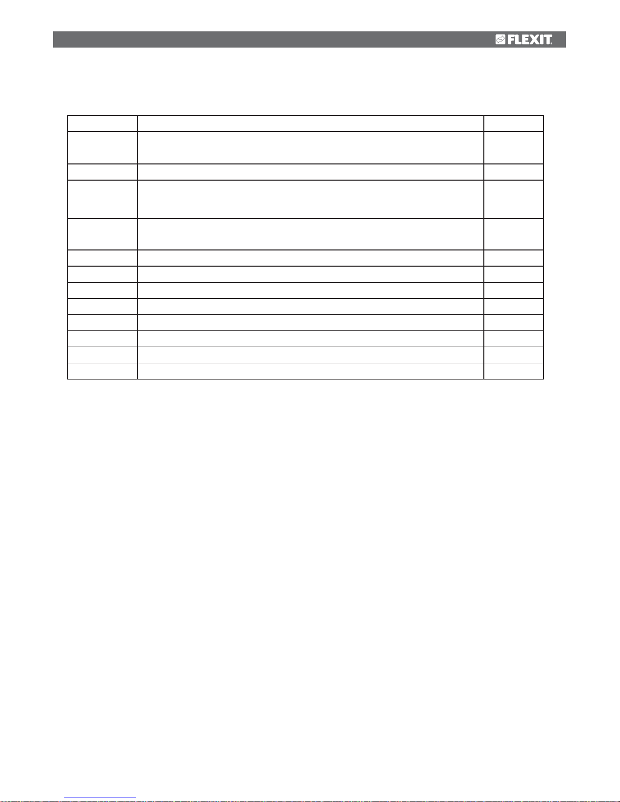
9 Maintenance table
Component Interval
Filters Filters should be changed at least once a year. You are advised to change them twice a
year.
6-12 months
Before and after the pollen season. Check that the filter seal is completely tight.
Fans
Fans should be cleaned at least once a year to maintain fan efficiency. If the kitchen
hood is used often, the extract air fan must be checked and if necessary cleaned
every four to six months.
4 months
Heat exchanger
Check that the surfaces are clean. Check that the sealing strips lie in against the heat
exchanger.
12 months
Make sure that rotor driving belt is in good condition and well adjusted. 12 months
Kitchen hood Wash the grease filter. Check that the damper is clean and closes fully. 2 weeks
Seals Check that the seals in the unit are intact. 12 months
Valves To be cleaned at least once a year. 12 months
Air intake Check that no leaves and other items are caught in the grille. 12 months
Roof cowl If the unit has a roof cowl, this must be checked for leaves and the like. 12 months
Also check that the drain slots are open.
Ducts Check that the ducts are clean. 10 years
Page 20
20
10 Troubleshooting
In the case of a power cut, the unit will automatically return to normal operation (user's settings)
when starting up again.
If none of this helps, please contact your supplier
for service. Please state the model designation
and serial number (on the rating plate inside the
unit/open door).
Type of fault: Remedial action:
Cold draughts Check which supply temperature has been selected. See operating panel.
Check that the rotor is rotating.
Check that heating comes on.
Needs new extract filter.
Fans not working Check that the power to the unit is connected.
Check that the
overheating thermostat has not cut out.
Reset by pressing the button. Also needs correcting on the automatic control panel.
Check that the unit has not been set in stop position.
Low air volume Check the speed the unit is set to.
Check that the filters fit tightly.
Check the intake grille.
The unit has a safety switch which cuts off power
when the door is removed.
Page 21
21
11 EC Declaration of Conformity
This declaration confirms that the products meet the
requirements in the following Council Directives and
standards:
2004/108/EF Electromagnetic Compatibility (EMC)
2006/95/EF Low-voltage Directive (LVD)
98/37/EEC Machine Directive (Safety)
Manufacturer: FLEXIT AS, Televeien 15, 1870
Ørje, Norway
Type: K2 R Ventilation unit
Conforms to following standards:
The product has been CE-marked: 2011
FLEXIT AS 16.02.2011
Frank Petersen
CEO
Safety standard EN 60335-1:2002
EMF standard: EN 50366:2003
EMC standard: EN 55014-1.2000
EN 61000-3-2:2000
EN 61000-3-3:1995
EN 55014-2:2:1997
The right to give notice of lack of conformity applies to this product in
accordance with the existing terms of sale, provided that the product is used
and maintained correctly. Filters are consumables.
The symbol on the product shows that this product must not be
treated as household waste. It must be taken to a reception station
for recycling of electric and electronic equipment.
By ensuring the correct disposal of the equipment, you will contribute
to preventing the negative consequences for the environment and
health that incorrect handling may entail. For further information
on recycling of this product, please contact your local authority, your refuse
collection company or the company from which you purchased it.
Notice of lack of conformity as a result of incorrect or defective installation must
be submitted to the installation company responsible. The right to give notice of
lack of conformity may lapse if the system is used incorrectly or maintenance is
grossly neglected.
Page 22

22
a
Page 23

23
a
Page 24

Flexit AS, Televeien 15, N-1870 Ørje www.flexit.no
 Loading...