


116026EN-03
2019-10
Eq 2
Assembly and Operation Instructions
Heat recovery single-room reversible ventilation unit
ART. NO.:
116001

EQ 2
2

Contents
2. Purpose ....................................................................................................................................................................................................................... 6
3. Delivery set
1. Technical data
4. Product description
5. Mounting and set-up
5.1. Wall-mounted control panel installation and connection
5.2. Unit mounting
6. Connection to power mains and control
7. Technical maintance
8. Troubleshooting
9. Storage and transportation regulations
10. CE Declaration of conformity
.......................................................................................................................................................................................................... 6
................................................................................................................................................................................................ 6
............................................................................................................................................................................. 8
......................................................................................................................................................................10
..............................10
........................................................................................................................................................................... 12
.................................................................................................... 16
....................................................................................................................................................................... 19
....................................................................................................................................................................................... 21
.................................................................................................... 21
.........................................................................................................................................22
EQ 2
3
!
SAFETY REQUIRE-
!
MENTS
EQ 2
• Read the user’s manual carefully prior to
installing and operating the unit.
• Fulfil the user’s manual requirements as well
as the provisions of all the applicable local
and national construction, electrical and
technical norms and standards.
• The warnings contained in the user’s
manual must be considered most seriously
since they contain vital personal safety
information.
The user’s manual consisting of the technical details,
operating instructions and technical specification applies
to the installation and mounting of the single-room energy
CAUTION! When a text bears this
symbol, it means that personal injury
or serious damage to the equipment
may result if the instructions are not
followed.
• Failure to follow the rules and safety
precautions noted in this user’s manual may
result in an injury or unit damage.
• After a careful reading of the manual, keep it
for the entire service life of the unit.
• While transferring the unit the User’s manual
must be turned over to the receiving
operator.
recovery reversible ventilator Eq 2 (hereinafter referred to
as «the unit»).
NB! When a text bears this symbol,
damage to equipment or poor
efficiency may be the consequence
of not following the instructions.
The right to give notice of lack of conformity
applies to this product in accordance with the
existing terms of sale, provided that the product is
used correctly and maintained.
Filters are consumables.
The symbol on the product shows that this product must not
be treated as household waste. It must be taken to a collection point for recycling electrical and electronic equipment.
By ensuring correct disposal of the equipment, you will
contribute to preventing negative consequences for the
environment and health that incorrect handling may entail.
For further information on recycling of this product, please
contact your local authority, your refuse collection company
or the company from which you purchased it.
Notice of lack of conformity as a result of incorrect or
defective installation must be submitted to the installation
company responsible. The right to give notice of lack of
conformity may lapse if the system is used incorrectly or
maintenance is grossly neglected.
This appliance may be used by children of 8 years or above or
by persons with reduced sensory capacity or reduced physical
or mental capacity, or by persons with lacking experience or
knowledge, provided they have received instructions in the safe
use of the appliance or are supervised to ensure safe use and
providing they are aware of the risks.
The product is not suitable for use by children. Children must not
be allowed to play with the appliance. Children must not carry
out cleaning or maintenance without supervision.
Our products are subject to continuous development and we
therefore reserve the right to make changes.
We also disclaim liability for any printing errors that may occur.
4
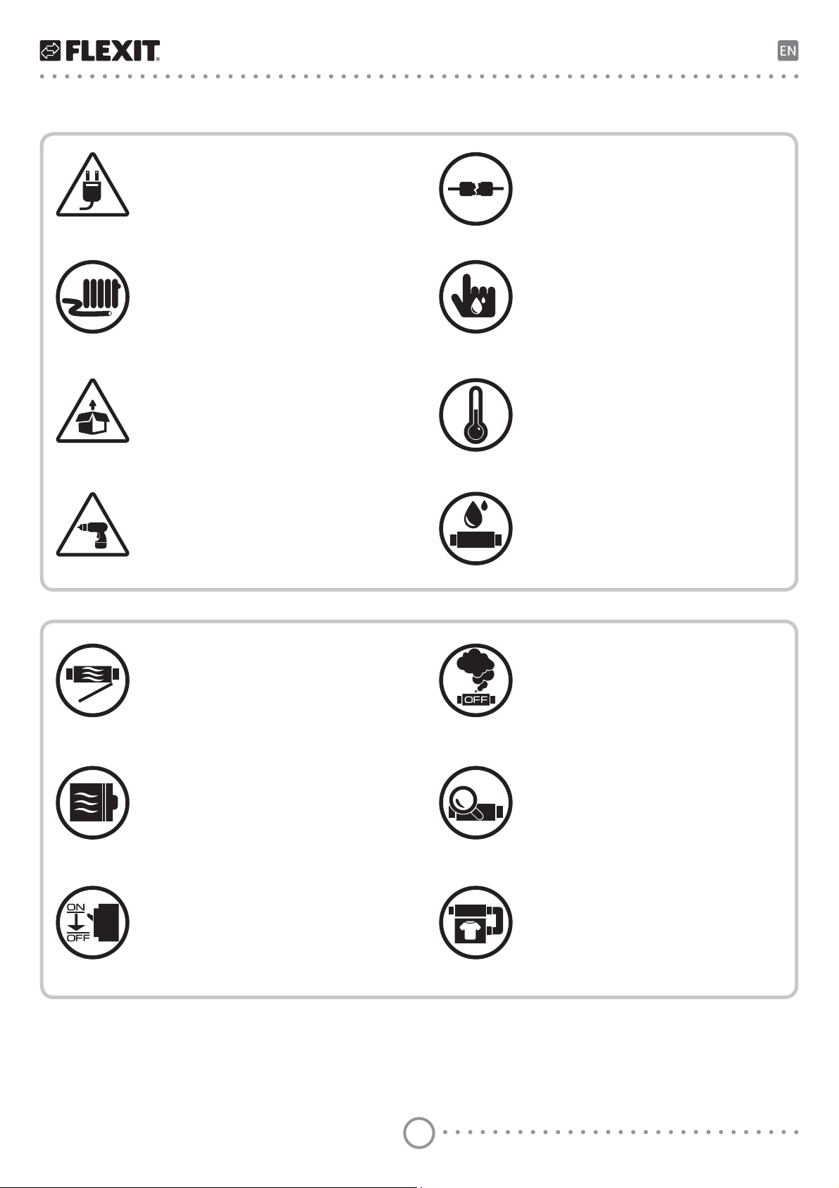
Unit mounting and operation safety precautions
• Disconnect the unit from power mains
prior to any installation operations.
• Do not lay the power cable of the unit in
close proximity to heating equipment.
• Unpack the unit with care.
• While installing the unit follow the safety
regulations specific to the use of electric
tools.
• Do not use damaged equipment or
cables when connecting the unit to
power mains.
• Do not touch the unit controls with wet
hands.
• Do not carry out the installation and
maintenance operations with wet hands.
• Do not operate the unit outside the
temperature range stated in the user’s
manual.
• Do not operate the unit in aggressive or
explosive environments.
• Protect the electric parts of the unit
against ingress of water.
• Do not open the unit during operation.
• Do not block the air duct when the unit is
switched on.
• Disconnect the unit from power mains
prior to any technical maintenance.
• If the unit generates unusual sounds,
odour or emits smoke disconnect it from
power supply and contact the Seller.
• In case of continuous operation of the
unit periodically check the security of
mounting.
• Use the unit only for its intended
purpose.
EQ 2
5
EQ 2
!
!
2. Purpose
The unit is designed to ensure continuous mechanical air
exchange in houses, apartments, commercial buildings and
other utility and public spaces.
The unit is equipped with a ceramic regenerator that enables
supply of fresh filtered air heated by means of extract air
heat energy regeneration.
The unit is designed for through-the-wall mounting.
The choice of unit installation location
must prevent unauthorized access by
unattended children.
The unit is rated for continuous operation.
Transported air must not contain any flammable or explosive mixtures, evaporation of chemicals, sticky substances,
fibrous materials, coarse dust, soot and oil particles or
environments favourable for the formation of hazardous
substances (toxic substances, dust, pathogenic germs).
3. Delivery set
Name
Air duct 2 item
Sound-absorbing layer 2 item
Assembled cartridge 2 item
Internal square ventilation grille 2 item
External grille, aluminium 2 item
External grille, plastic* 2 item
Control panel 1 item
Fastening set 1 pack
Mounting box 2 item
User's manual 1 item
Packing box 1 item
*available
Number
Turn off the unit if the air temperature
is outside the temperature range
stated in the technical data.
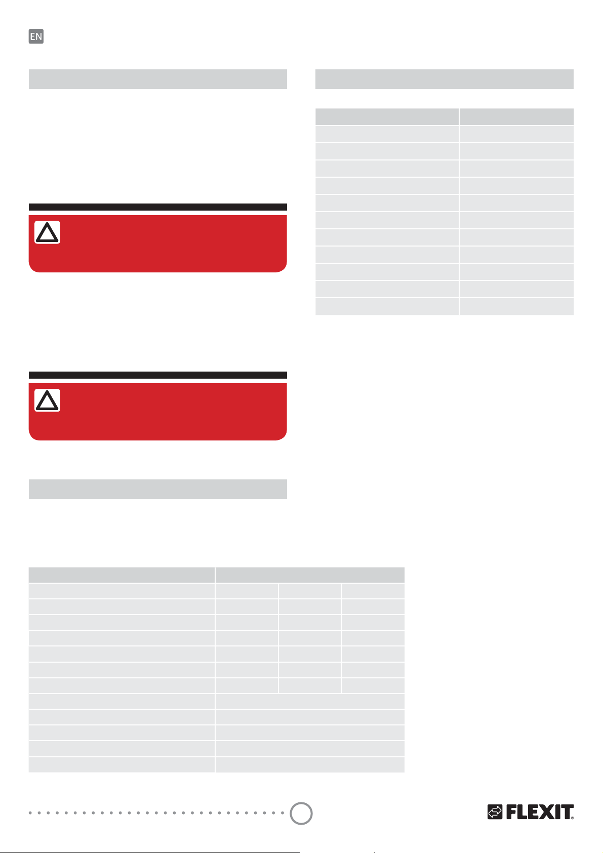
1. Technical data
The unit is designed for indoor use. The units is constantly
being improved, so some models can slightly differ from
those ones described in this manual.
Eq 2 (2 units)
Speed I II III
Airflow (m
Sound pressure* Lp(A) 3m dB 19 28 37
Sound power* Lw(A) dB
Power consumption* (W) 1,6 3 5,6
Current* (A) 0,018 0,032 0,06
Fan speed (rpm) 1030 1760 2690
Voltage (V/50-60Hz) 100-240V
Filter class
Ingress protection IP 24
Operating temperature
Wall thickness 350-500 mm
3
/h) 15 30 50
36 45 54
G3 (F8 accessories)
** -25°C to 50°C
**Minimum operating temperature is
measured at an indoor humidity of 35% RH.
Variations in temperature and humidity may
lead to freezing at higher temperatures
than specified.
In the event of possible freezing, take the
cassette out with the heat recovery system
and fan. Let it thaw at room temperature.
Wait to start the room fan if the
temperature and humidity conditions are
unchanged. Minimum speed reduces the
risk of frost.
* Per unit
6

241 mm
Air duct length, 500 mm
180/ 200
160
241 mm
External grille
Decorative panel
Ø160 mm
The duct can be cut at 350 mm. Not shorter due to the outer
grille and the heat exchanger.
Hoods for thinner walls are available as accessories. Min. wall
thickness can with theese be reduced by 100 mm.
86 mm
42,5 mm
13,5 mm
82 mm
350-500
42.5
240
*aluminium grille/plastic grille
R 2 mm
68 mm
4 mm
Control panel
The sensor panel contains touch buttons for unit control and
an emergency indicator.
Boxes for both flush and on wall mount are included in the
package.
Unit voltage [V /50-60 Hz] 110-230
Temperature range [˚C] from +10 up to +45
Humidity range [%] 10 - 80 (no condensation)
Service life, switching operations 100 000
Ingress protection IP30
Weight [g] 190
EQ 2
7
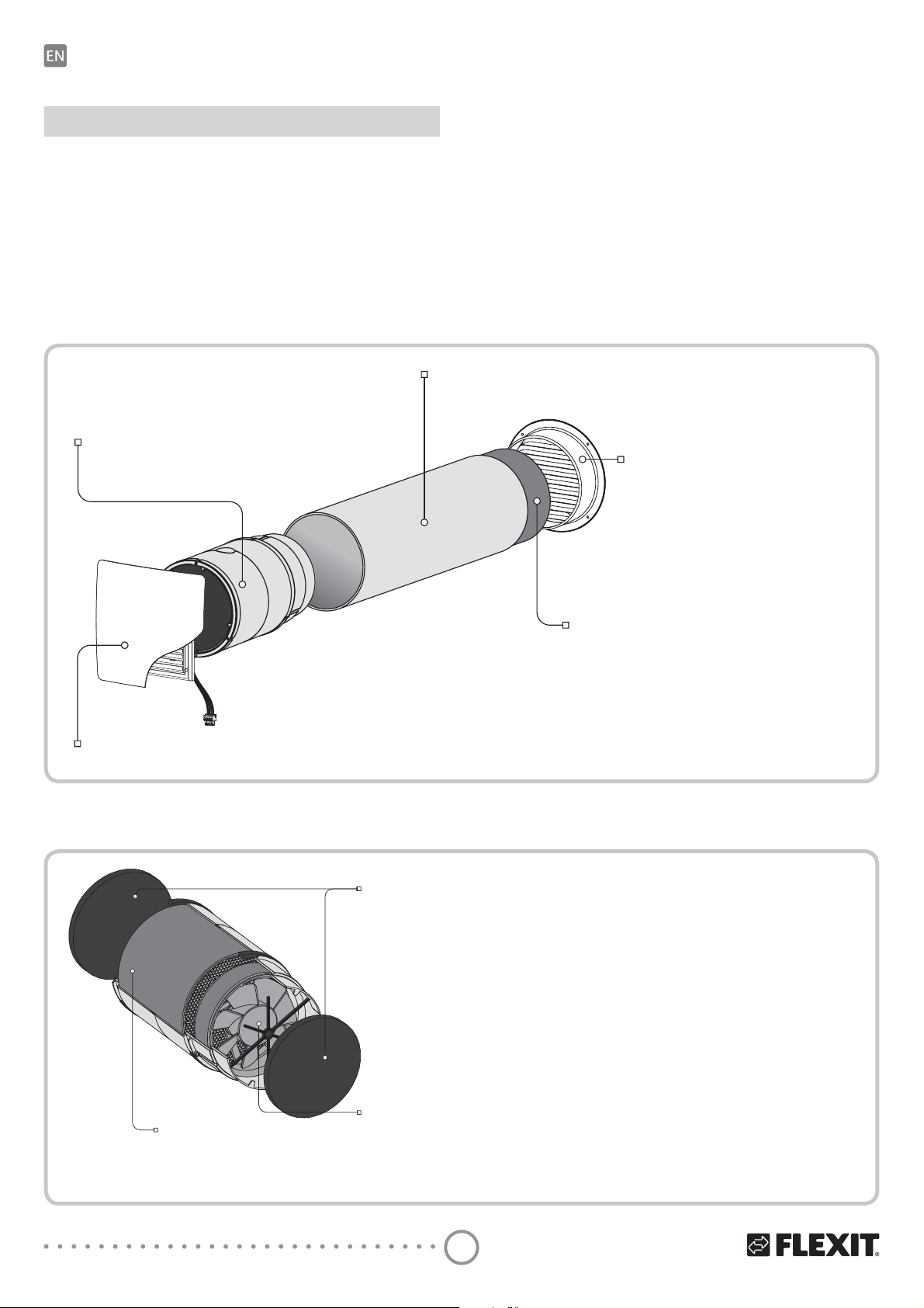
4. Product description
EQ 2
The unit consists of a protecting internal grille with a decorative panel, a cartridge, an air duct and a protecting external
ventilation grille or a hood.
The cartridge is the basic functioning part of the unit.
The cartridge consists of a fan, a regenerator and two filters
that ensure rough air filtration and prevent ingress of dust
Unit design
Cartridge
Generates air flow, provides
energy recovery and air cleaning.
and foreign objects into the regenerator and the fan.
The internal grille is equipped with manually actuated shutters which can close the air duct during the unit standstill.
The external protective grille on the outer wall prevents
ingress of water and foreign objects into the unit.
Air duct
Plastic air duct
External grille
Protects the unit from ingress of water
and foreign objects.
Internal ventilation grille with a decorative panel
Equipped with manually actuated louvre shutters.
Cartridge design
Filter
Cleans the air flowing through
the ventilator of dust and foreign
objects.
Prevents contamination of the
regenerator.
Sound-absorbing material
Serves for sound attenuation of outdoor noise.
Cartridge is a block consisting
of removable filters and a solid
fan-regenerator unit.
The filters are easy removable
for maintenance.
Regenerator
Provides extract air energy
regeneration for warming
up of supply air flow.
Fan
Generates air flow
8
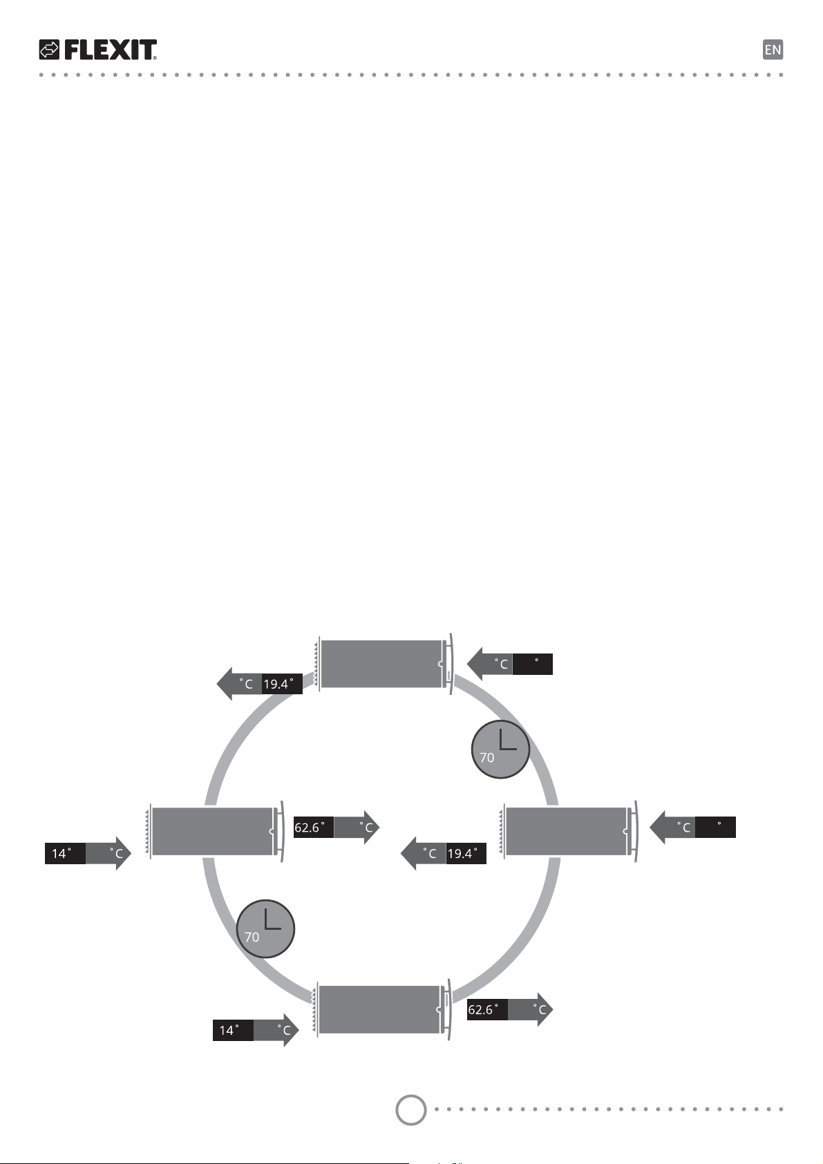
Unit operation modes
The unit has two ventilation modes:
Regeneration. The unit operates in reversible mode with
heat and humidity regeneration in two cycles, 70 seconds
each.
Ventilation. The unit operates in permanent supply or
extract mode at set speed. In case of two units operating in
this mode one unit operates in supply and the other one in
extract mode.
Cycle I.
As warm stale extract air flows through the ceramic regenerator, it heats up and moisturizes the regenerator and
transfers up to 97 % of heat energy.
In 70 seconds as the ceramic regenerator gets warmed the
unit is switched to supply mode.
Cycle II.
Fresh intake air from outside flows through the ceramic
regenerator, absorbs accumulated moisture and is heated
up to the room temperature.
In 70 seconds as the ceramic regenerator gets cooled down,
the unit is switched to air extract mode and the cycle is
renewed.
In this operation mode, in case if two units are installed each
of them operates two cycles in opposite phases.
While one unit operates in air supply mode the other one
operates in air extract mode.
Example:
+20
F-7
+17F
-7 F-10F
s
AIR SUPPLY
-10F
68 F
AIR EXTRACT
s
F
+17
+20 68 F
EQ 2
9

5. Mounting and set-up
!
!
5.1. WALL-MOUNTED CONTROL PANEL
INSTALLATION AND CONNECTION
EQ 2
Installation and connection of control
panel shall only be performed by
professional electrician.
Make sure that the control panel is not
damaged. Do not use a damaged
control panel!
1. a) Flush mount
Prepare a hole in the wall and route all the wires to the
installation place. Insert the supplied mounting box for
flush wall mounting. The mounting box is included in
delivery.
Do not install the control panel on an
uneven surface!
While tightening the screws, do not
apply excessive force to prevent the
control panel casing deformation.
74
mm
34
4
mm
mm
1. b) On-wall mount
Fix the supplied mounting box for on-wall mount onto
the wall. The mounting box is included in the delivery.
88
mm
32
mm
10

2. Use a screwdriver to carefully undo the clips on the
backside of the control panel and remove the back
cover.
3. Screw the backside of the casing to the mounting
box through the fastening holes. Fastening screws for
mounting of the control panel are included in the control
panel delivery set. Then connect the cable to the control
panel in compliance with the wiring diagram, page 16.
4. Install the control panel display and press it to fix.
EQ 2
11

5.2. UNIT MOUNTING
!
min 3 °C
Read the user’s manual prior to mounting the unit.
Do not block the air duct of the installed unit with dust accumulating materials, such as curtains, cloth shutters,
etc. As it prevents air circulation in the
room.
EQ 2
1. Prepare holes for the air ducts.
Prepare a round core hole in the outer wall, depending
on the unit equipment.
For efficient operation of the ventilation system it is
recommended to install the units as far apart from one
another as possible.
2. Prepare air ducts of required length.
Measure the wall thickness.
Cut the air duct so it fits flush on both sides of the wall.
Min. length is 350 mm.
Cut the air duct on the outher side which don´t have
cable grooves.
Insert the air duct into a prepared hole in the wall.
The cable grooves must be located on inner wall side.
When making holes, we recommend ensuring that the
power cables and control cables are in order.
Recommended hole dimension;
When using an external metal grille: Ø170 mm
When using an external plastic grille: Ø180 mm
Polystyrene wedge
Fill the gap between the air duct
and the wall with mounting foam
or similar.
12

3. Install the sound-absorbing layer in the air duct.
Prior to installation adjust its length with respect to the
dimensions of the cartridge, external grille or the outer
ventilation hood as well as the internal square or round
grille.
This example shows adjustment of the soundabsorbing layer length calculated from the flange
width of the square inner grille.
Insert the cartridge during adjustment in the air duct.
L = 40 mm
During adjustment of the insulation layer length cover
the air duct and the cartridge with the internal grille.
Roll the sound-absorbing layer to match the air duct
diameter with the protecting paper layer outside and
insert the roll in the air duct against stop.
Do not remove the paper layer!
The adjustment of the sound-absorbing layer length
for the unit with an external grille
Mark the sound-absorbing layer at the end of the air
duct (1).
From the mark (1) measure 55 mm and make a new
mark (2). Cut the excessive part of the soundabsorbing layer.
Insert the adjusted and ready sound-absorbing layer
into the air duct.
No glue is required for fixation!
The adjustment of the sound-absorbing layer length
for the unit with an outer hood (accessories)
Mark the sound-absorbing layer at the end of the air
duct (1). Cut the excessive part of the sound-absorbing
layer.
Insert the adjusted and ready sound-absorbing layer
into the air duct.
No glue is required for fixation!
50 mm (2”)
1
1
2
1
EQ 2
13

4. Insert the air duct in the wall.
Install the air duct with the sound-absorbing layer with
minimum slope 3° downwards using polystyrene wedges.
Fill the gaps between the wall and the opening with a
mounting foam.
Make sure that moisture cannot permeate into the
opening in the external wall. Use a suitable sealant.
To enable easy installation of the cartridge in the air duct
cut out a recess in the mounting foam layer on the side
of the cable installation parallel to the groove in the air
duct.
For freedom of placement of the cable in the groove
without any damage to the cable insulating material, cut
off the excess of the mounting foam.
EQ 2
Fill the gaps between the wall
and the opening with a mounting
foam or similar
min 3 °C
Polystyrene wedge
5. Install the cartridge in the air duct.
14

6. Connect the socket connector from
the control panel in compliance with
the external wiring diagram. Connect
the socket connectors of the cartridge
and the control panel.
7. Install the internal grille and fix the external grille.
External grille
For mounting of the outer ventilation hood, please refer to a
respective hood installation instruction.
Internal grille with a decorative panel
EQ 2
15

6. Connection to power mains and control
!
!
!
Disconnect the unit from power supply
prior to any electric installation operations.
The following installation shall only be
performed by a professional electrician according the instruction in the
user manual.
The rated electrical parameters are
stated on the rating plate. Any tampering with the enternal connections is
prohibited and will void the warranty.
EQ 2
Wiring diagram
Unit 2
(supply*)
YELLOW
BLUE
RED
T P +
+
T2
P2
+
T2
P2
BLACK
-
-
-
Unit 1
(extract*)
YELLOW
BLUE
T P +
T1
P1
T1
P1
The unit is rated for connection to single-phase AC 100-240
V/ 50-60 Hz power mains.
The units shall be installed according to current laws and
regulations.
Signal cables shall be shielded and with a minimum cross
2
section of 0.25 mm
RED
BLACK
.
Connect the units to power mains in compliance with the
wiring diagram.
-
100230 V
-
+
+
5060 HZ
-
L
N
*in ventilation mode only
16

Unit control
!
The unit is operated with the control panel.
The control panel must be installed in
the included mounting box during
operations.
Press the buttons precisely on the
control panel. Pressing the buttons
quickly and shortly may result in
malfunction of the unit!
The following parameters are set with the control panel:
• unit operation speed: I, II, III;
• unit operation mode: REGENERATION or VENTILATION;
• timer-based operation of the unit: 4 hours at speed III or 8
hours at speed I.
The control panel displays the following parameters:
• current unit speed
• current operation mode of the unit
• timer operation status (on/off)
• filter replacement/cleaning need according to indications
of the filter timer (factory setting 90 days)
• emergency shutdown of the unit in case of a motor failure
In case of power cut-off the set parameters are saved in the
non-volatile memory of the control panel.
EQ 2
17

Timer
Speed III
4 hours
Speed III
Speed II
Speed I
Timer
Speed I
8 hours
EQ 2
Unit control with a sensor control panel
After expiry of the period set for the filter timer
(factory setting 90 days) the FILTER
contamination indicator starts glowing. In this
case clean or replace the filters and reset the
filter timer.
Resetting the filter timer and the operating
hours: press and hold the FILTER indicator.
REGENERATION
VENTILATION
The ALARM indicator glows in case of
emergency stop of the motor, as a result of
which the unit stops.
Resetting alarm indication: press and hold
the ALARM indicator until the indicators start
blinking rapidly.
Turning the unit on
Turning the unit off
Unit speed selection
Unit operation mode selection
Turning the timer on
Timer selection
Turning the timer off
Press any of speed selection buttons
Press the active speed button
Press the inactive speed button
Press the inactive REGENERATION
, , or the timer buttons , .
, , or the active timer button , , if no speed button is active.
, , .
or VENTILATION button.
The direction of air flow in the unit (supply and extract mode) is set when connecting the unit according to
the external connections wiring diagram.
Press the timer
Press the inactive timer
Press the active timer
button or .
button or .
button or .
If the timer period expires:
The unit continues operation at a set speed. The speed can be selected before switching on the timer as
well as during the timer-based operation.
The unit turns off if the speed was not selected.
18

To close the air duct pull a small handle between the
!
grille shutters to the left against stop.
To open the air duct pull this handle to the right.
7. Technical maintance
Air duct closing
Open
Close
Disconnect the unit from power supply
before any maintenance operations!
Maintenance of the unit means regular cleaning of the unit
surfaces of dust and cleaning and replacement of the filters.
To access the basic assembly units follow the steps:
Disconnect the socket connectors. Push the cable from
the control panel aside to the wall and pull the cord from
the cartridge to remove it from the air duct. Remove the
filters from the cartridge.
EQ 2
19

Clean the filters as they get contaminated, but not
less than once in three months.
• After expiry of the period set for the filter timer
(factory setting 90 days) the filter replacement
EQ 2
indicator
• Wash the filters and let those dry out completely.
Then install the dry filters in the air duct.
• Vacuum cleaning is allowed.
• The filter rated service life is 3 years.
• For new filters contact the Seller.
Even regular technical maintenance may not completely
prevent dirt accumulation on the regenerator and the
fan.
• Clean the regenerator regularly to ensure its high
regeneration efficiency.
• Clean the regenerator with a vacuum cleaner at
least once a year.
appears on the control panel display.
20

8. Troubleshooting
Problem Possible reasons Troubleshooting
The fan does not start up
during the unit start-up.
The control panel displays
no information and does
not respond to the button
pressing.
The control panel displays an
alarm indicator
Automatic switch tripping
following the unit turning on.
Low air flow.
Noise, vibration. The impeller is clogged. Clean the impeller.
No power supply.
Motor is jammed, the impeller blades are clogged.
Communication loss in connecting cable between the
.
fan motor and the control panel.
Overcurrent as a result of short circuit in the electric
line.
Low set fan speed. Set higher speed.
The filters, the fan or the regenerator are clogged.
Make sure the power supply line is connected correctly, otherwise troubleshoot the connection error.
Turn the unit off. Clean the impeller to troubleshoot
the motor jam. Restart the unit.
Turn the unit off. Contact the Seller for further
information.
Turn the unit off.
Contact the Seller for further information.
Clean or replace the filter. Clean the fan and the heat
exchanger.
9. Storage and transportation regulations
Store the unit in the manufacturer’s original packing box in a
dry ventilated premise at ambient temperatures from +5 °C
up to +40 °C.
Storage environment must not contain aggressive vapours
and chemical mixtures provoking corrosion, insulation and
sealing deformation.
Use suitable hoist machinery for handling and storage operations to prevent possible damage to the unit.
Follow the handling requirements applicable for the particular type of cargo.
The unit can be carried in the original packing by any mode
of transport provided proper protection against precipitation
and mechanical damage.
Avoid sharp blows, scratches or rough handling during
loading and unloading.
Do not expose the unit to sudden changes in temperature.
Such changes can lead to condensation of moisture inside
the unit and performance disturbance when the unit is
switched on.
Prior to the initial power-up after
transportation at subzero
temperatures allow the unit to warm
up at room temperature for at least 2
hours.
EQ 2
21

10. CE Declaration of conformity
EQ 2
This declaration confirms that the products meet the
requirements in the following Council Directives and standards:
2014/30/EC Electromagnetic compatibility (EMC)
2014/35/EC Low-voltage Directive (LVD)
93/68/EEC CE-marking Directive on the
approximation of the laws of the
Member States relating to
electromagnetic compatibility.
Producer: VENTILATION SYSTEMS PrJSC
1, Mikhaila Kotzubinskogo St., Kiev, 01030,
Ukraine
Type: Single-room ventilators;
Roomie One Wifi
Roomie Dual
Roomie Dual Wifi
Eq 2
Art.no.: 115996, 115999, 116000, 116001
Compliance with valid versions of the following standards on
the date on which the declaration of conformity was signed:
Safety standard: EN 60335-1
EN 60335-2-80
EMF standard: EN 62233
EMC standard: EN 55014-1
EN 55014-2
EN 61000-3-2
EN 61000-3-3
Flexit AS 30.11.2016
Frank Petersen
CED
22

EQ 2
23

Flexit AS, Televeien 15, N-1870 Ørje www.flexit.no
 Loading...