

Page 1

112140E-06
2019-09
CS2000 Automatic control V3
User Guide
Page 2

Contents
This user guide only applies to software version V3.x
To view current software version:
Start page > Main menu > System Overview > Versions > Flexit.ahu = V3.x
!
1. Introduction
1.1. Document description ................................................................................................................................4
1.2. Highlighted boxes ........................................................................................................................................4
1.3. System overview ..........................................................................................................................................5
1.3.1. System structure ....................................................................................................................................5
1.3.2. Ventilation unit's switching space ......................................................................................................6
1.3.3. Ventilation unit's control cabinet .......................................................................................................7
2. Getting started
2.1. HMI ..................................................................................................................................................................9
2.2. Settings ..........................................................................................................................................................9
2.2.1. Introduction ............................................................................................................................................9
2.2.2. Select language......................................................................................................................................9
2.2.3. Login .........................................................................................................................................................9
2.2.4. Set time/time channels .......................................................................................................................10
2.3. Adjust the setpoints for speeds and temperatures ............................................................................12
2.4. Service switch ............................................................................................................................................. 12
2.5. Extract air regulation ................................................................................................................................ 12
2.6. Change the unit for the flow display ......................................................................................................12
2.7. Alarm handling .......................................................................................................................................... 12
3. Menu tree ...................................................................................................................................................13
4. Backup and program updates
4.1. Save a configuration ................................................................................................................................ 25
4.2. Load a configuration ................................................................................................................................ 25
4.3. Loan an application or software ............................................................................................................ 25
4.4. Error diagnosis - Snapshot ..................................................................................................................... 26
5. General functions ...................................................................................................................................26
6. Configuration
6.1. Configuration 1 .......................................................................................................................................... 27
6.2. Configuration 2 .........................................................................................................................................32
6.3. Configuration of inputs and outputs ..................................................................................................... 36
7. Cooling
7.1. Installation ..................................................................................................................................................37
7.2. Configuration - Cooling control ..............................................................................................................37
7.3. For activation of circulation pump (only applies to liquid cooling) ................................................37
7.4. Blocking in connection with outdoor temperature .............................................................................37
7.5. Operating times (only applies to DX cooling) ......................................................................................37
7.6. Cooling restriction depending on fan speed (only applies to DX cooling) ................................... 38
7.7. Setting of temperature setpoint ............................................................................................................ 38
2
Page 3

8. Temperature regulation
8.1. Extract air regulation ............................................................................................................................... 38
8.2. To adjust supply air temperature limits with extract air regulation................................................ 38
9. Summer/winter compensation
9.1. Adjustment of fan setpoint in connection with high/low outdoor temperature .......................... 39
9.2. Parameter settings for fan compensation .......................................................................................... 39
9.3. Adjustment of temperature setpoint in connection with high/low outdoor temperature ......... 39
9.4. Parameter settings for temperature compensation ......................................................................... 39
9.5. Settings for switching between summer and winter operation ....................................................... 40
9.6. Switch between summer and winter via signal ................................................................................... 40
9.7. Switch between summer and winter via date/outdoor temperature .............................................. 41
9.8. Temperature test for nighttime operation ........................................................................................... 41
9.9. Nighttime cooling ..................................................................................................................................... 42
9.10. Support operation .................................................................................................................................... 42
9.10.1. To activate the function..................................................................................................................... 42
9.10.2. To configure the function .................................................................................................................. 42
10. Fan regulation
10.1. Select method of regulation ....................................................................................................................43
10.1.1. Selection fan regulation method ......................................................................................................43
10.2. Pressure control .........................................................................................................................................43
10.2.1. Configuration of the pressure sensors’ measuring ranges .........................................................43
10.2.2. Pressure setpoint adjustment. ........................................................................................................ 44
10.3. External fan setpoint ............................................................................................................................... 44
10.3.1. Parameter settings for Comp. .......................................................................................................... 45
10.3.2. Parameter settings for Main ............................................................................................................. 45
10.4. External fan control via digital inputs ................................................................................................... 46
10.5. Fire fan ........................................................................................................................................................ 46
11. Connection of external equipment
11.1. Fire damper ................................................................................................................................................ 47
11.2. Fire/smoke detector ................................................................................................................................. 50
11.3. Air quality .................................................................................................................................................... 51
11.4. AUX Damper .............................................................................................................................................. 52
12. Web ..............................................................................................................................................................53
13. ModBus TCP/IP ........................................................................................................................................ 54
14. DX heating/cooling ...............................................................................................................................55
14.1 Configuration of control system ...........................................................................................................55
14.2 Installation ................................................................................................................................................56
3
Page 4
1. Introduction
!
!
1.1. Document description
This document describes the main functions of the CS2000 automatic control and is divided into different sections for
different parts of the system. If you only want to make basic settings to start the ventilation unit, there is a special section
describing the startup procedure. If you require more detailed information, select the relevant section in the document.
All electrical connections must be made
by an expert.
1.2. Highlighted boxes
A number of different text boxes are used in the document to draw the user's attention to various things. This may be anything
from pure information text to particularly important details to ensure that the system is not used incorrectly. Here is a brief
description of the various boxes:
WARNING! When a text is highlighted like
this, it means that personal injury or serious
damage to the equipment may result if the
instructions are not followed.
NB! When a text is highlighted like
this, it means that the equipment may
be damaged or function poorly if the
instructions are not followed.
RESTART
> EXAMPLE
Italicised text boxes show examples
A table looks like this
with various values with various values
with various values with various values
4
Page 5
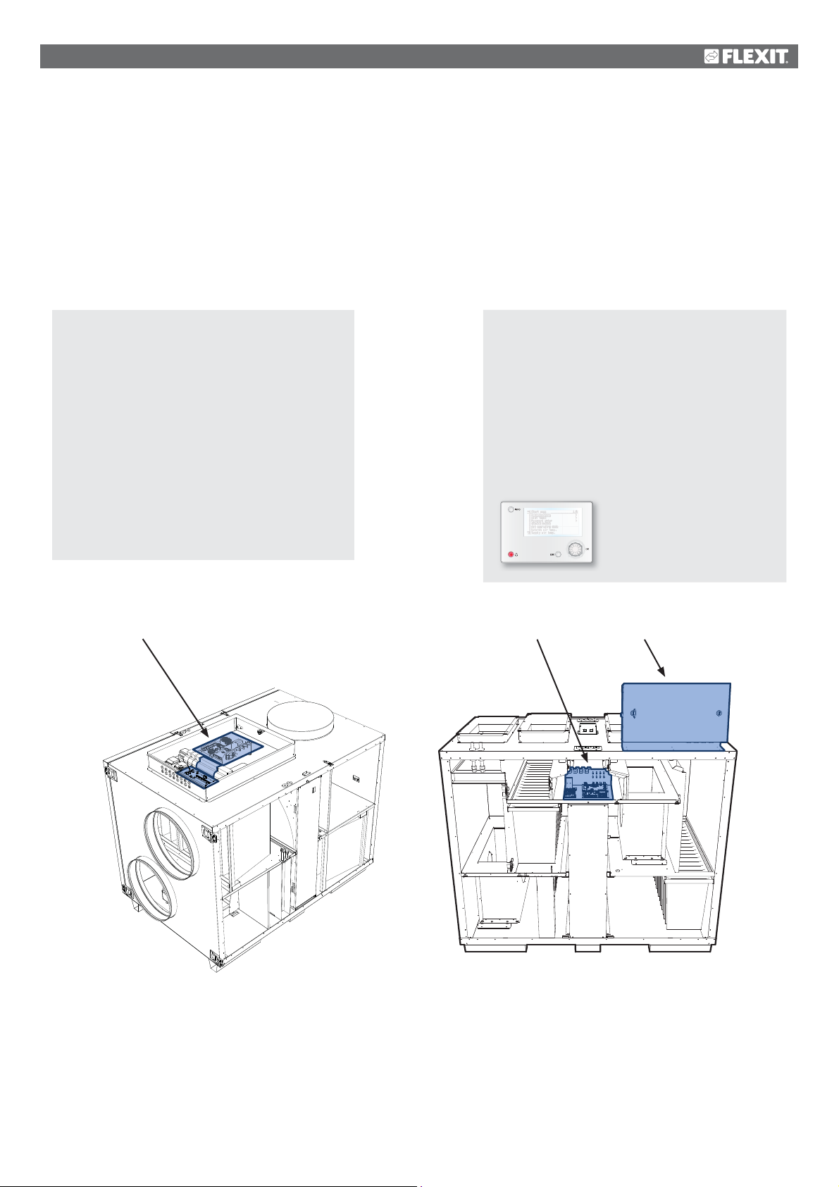
1.3. System overview
1.3.1.
The control system is divided into two subgroups:
1. One part that is located in the ventilation unit's switching space
2. One part that is located in a separate control cabinet on the outside of the ventilation unit
System structure
1.
Terminal blocks for incoming feed
Fuse for automatic control and fans (not electric
heating coil)
Modbus extender - a communication card that
connects the ventilation unit's components to
the regulator via data communication
Power supply board - a circuit board that
distributes the power supply to the ventilation
unit's components and makes it possible to
connect components to a water heating coil
1, 2
2.
Regulator - the overall control system of the
ventilation unit
Terminal board - a circuit board with terminal
blocks for connection of additional components
and accessories
HMI - the control panel used to communicate
with the regulator
1 2
L model S model
5
Page 6
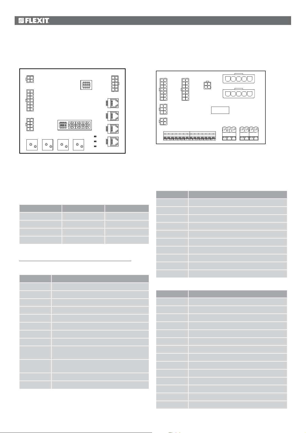
1.3.2.
Ventilation unit's switching space
Modbus extender
A3
123
P1
4
128
9
3410
11
P2
5612
13
714
125
6
P3
347
8
Q1 Q2
USER
FACTORY
FP1 FP2
1095
4
873
P8
2
61
P7
P6
P5
P4
It is a communication card that connects the ventilation
unit's components to the regulator.
The card has four dipswitches called 'USER' that are used
to configure the unit, depending on the type of heating coil
installed.
Dipswitch no. ON OFF
1 Heating coil No heating coil
2 Electric heating coil Water heating coil
3 - Must be OFF
4 - Must be OFF
The other four dipswitches and the rotary switches marked
'FACTORY' are factory-set and must not be changed.
The board's components have the following functions.
Component Function
P1 Power supply
P2 Control signals to heating coil
P3 Control signals to rotor and temperature sensor
P4 Communication connection
P5 Communication connection
P6 Communication connection
P7 Communication connection
P8 Control signals to fans
Q1 Differential pressure monitor for flow
measurement on supply air fan
Q2 Differential pressure monitor for flow
measurement on extract air fan
FP1 Differential pressure monitor for supply air filter
FP2 Differential pressure monitor for extract air filter
Power supply board
A4
18
29
310
411
P6 P7
512
613
714
14
25
P5
36
13
P4
24
1 2 3 4 5 6 7 8 9
18
29
310
411
512
613
714
P3
34
12
P8
10 11 12 13 14
1 2345
P9
1 2345
P10
PE PE PE
P1P2
L1 L2 L3 N
It is a circuit board that distributes the power supply to the
components of the ventilation unit (not the electric heating
coil) and control cabinet.
There is also a terminal block for the components required to
regulate a water heating coil.
The board's components have the following functions.
Component Function
P1 Terminal block for power supply
P2 Terminal block for protective earth (PE)
P3 Terminal block for water heating coil
P4 Power supply to modbus extender
P5 Power supply to control cabinet
P6 Control signals to heating coil
P7 Control signals to heating coil
P8 Power supply to rotor control
P9 Power supply to supply air fan
P10 Power supply to extract air fan
Terminal block P3 has the following signals:
Block no. Function
1 Valve motor - G0
2 Valve motor - 24 V+
3 Valve motor - G0
4 Valve motor - control signal 0-10 V
5 G0 (for F10 or B5)
6 Overheating thermostat F10
7 Return water sensor B5
8 No connection
9N
10 Pump motor - relay contact
11 Pump motor - relay contact
12 L
13 N
14 L
6
Page 7
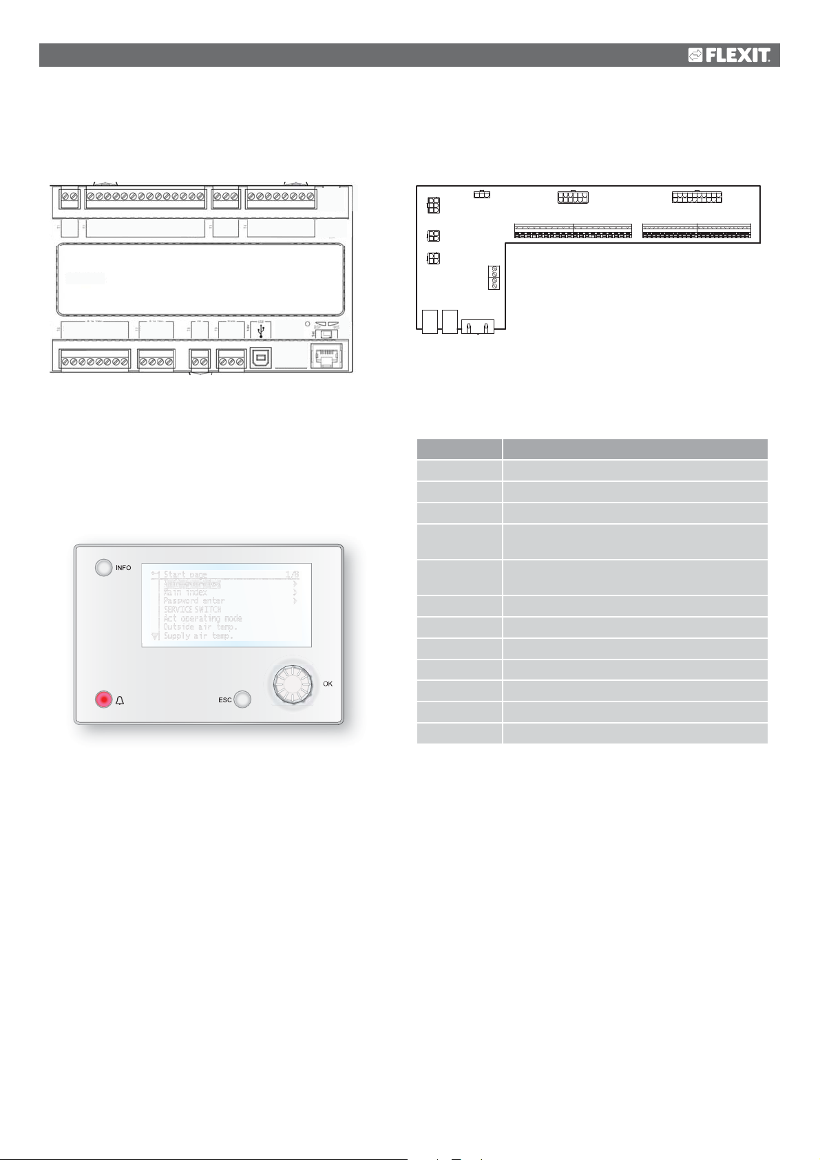
1.3.3.
Ventilation unit's control cabinet
Regulator
A1
X1MX2X3MX4X5MX6X7MX3+24V
0V
24V=
T1 T2 T3 T4
T6 T7 T8 T9
Q13
Q14
Q23
Q24
Q33
Q34
Q43
Q44
Q53
Q54
Q63
Q64
+24VY1M
CE -
CE+
Y2
REF
B -
A +
D1MD2D3MD4D5
M
The ventilation unit's control system. This is where the
control panel (HMI) and sensors and other components
of the ventilation unit are connected. It is also possible
to connect an SD memory card to back up or reload
configuration settings and parameters for the regulator.
HMI
The control panel on which all settings and readings take place.
It has an 8-line graphic display and you navigate the menu
tree using a dial that is turned. Selections are confirmed by
pressing the same button.
Terminal board
A2
12 7
4
2
5
P6
3
6
123
P5
4
123
P4
4
1312
P7
1 2 3 4 5 6 7 8 9
P14
P1P3 P2
1 2 3 4 5
829310411
16
5 623144155978
P8
10 11 12 13 14 15 16 17 18 19 20
20 11
12131819 1617
110
P9
P12P10
21 22 23 24 25 26 27 28 29 30 31 32 33 34 35 36 37 38 39 40 41 42 43 44
It is a circuit board that connects the components to
the regulator. External components such as dampers are
connected to this board via the terminal blocks on the board.
The board's components have the following functions.
Component Function
P1 Connection for power supply
P2 Data communication
P3 Data communication
P4 Connection for external pressure sensor
(accessory)
P5 Connection for external pressure sensor
(accessory)
P6 Connection for 24 V transformer
P7 Data communication
P8 Connection for digital outputs
P9 Connection for control signals
P10 Terminal block for 230 V signals
P12 Terminal block for control signals
P14 Terminal block for protective earth (PE)
7
Page 8
Terminal board
Terminal block P10 has the following signals:
Block no. Function
1L
2N
3 L (Outdoor air damper)
4 L1 (Outdoor air damper ON/OFF)
5 N (Outdoor air damper)
6 L (Exhaust air damper)
7 L1 (Exhaust air damper ON/OFF)
8 N (Exhaust air damper)
9 L (Fire damper)
10 L1 (Fire damper ON/OFF)
11 N (Fire damper)
12 Buzzer alarm IN
13 Buzzer alarm OUT
14 DX cooling/cooling pump IN
15 DX cooling/cooling pump OUT
16 L
17 Heating IN
18 Heating OUT
19 N
20 Not used
Terminal block P12 has the following signals:
Block no. Function
21 Cooling - 0-10 V [AO]
22 Cooling - G0
23 External control 1 [DI]
24 External control 1 - G0
25 External control 2 [DI]
26 External control 2 - G0
27 Fire/smoke [DI]
28 Fire/smoke - G0
29 Air quality - 0-10 [AI]
30 Air quality - G0
31 Heating - 0-10 V [AO]
32 Heating - 24 V+
33 Heating - G0
34 Fire damper open [DI]
35 Fire damper closed [DI]
36 Fire damper - G0
37 AUX damper - 0-10 V [AO]
38 AUX damper - G0
39 Return water sensor B5 [AI]/Overheating
thermostat F20 [DI]
40 Return water sensor B5 [AI] - G0 /
Overheating thermostat F20 [DI] - G0
External setpoint, supply air fan 0-10 V [AI] - G0
41 CE- [Data bus]
42 CE+ [Data bus]
43 External setpoint, supply air fan 0-10 V [AI]
44 External setpoint, extract air fan 0-10 V [AI]
8
Page 9
2. Getting started
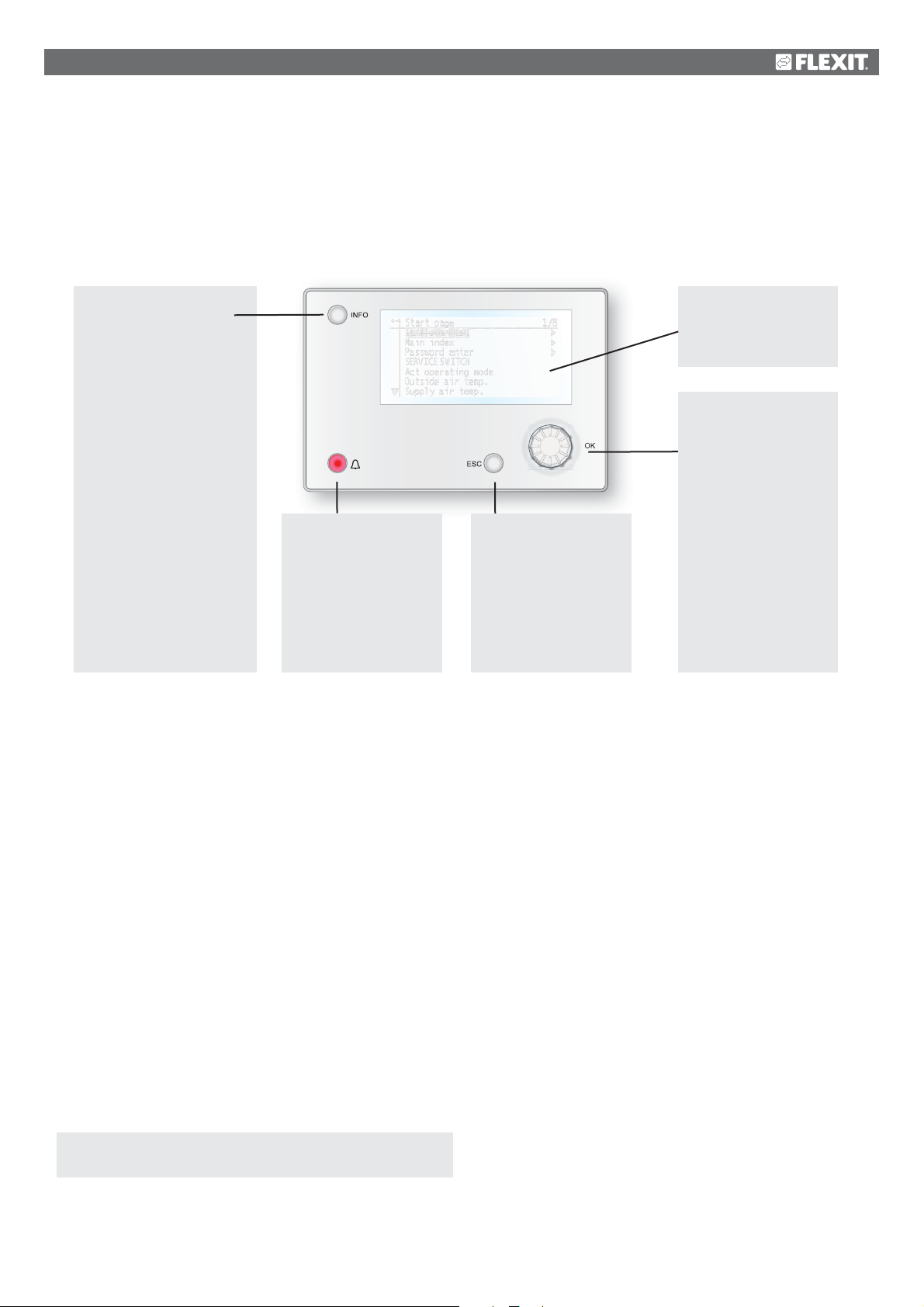
2.1. HMI
A central element in the system is the HMI (control panel), where you can adjust settings and take readings. The control panel
consists of an 8-line graphic display, indicator lamps and controls for the settings.
Here is a short introduction to the control panel showing how to enter the initial settings in the system.
Info button
Press to go to
Main Menu
• Off = Stop, cool down
• Green lamp, steady =
Normal operation
• Flashing green =
Starting, Night
operation test, Night
cooling or Night
heating/night cooling.
• Orange lamp, steady =
Emergency stop and
alarm with stop
• Flashing orange = Fire
damper in motion
• Alternating green/
orange = Manual
control
Alarm button
• Flashing red = alarm
• Red lamp, steady =
alarm acknowledged
but remaining
ESC button
• Returns to the
previous menu page
• Cancels current
editing
Display
Shows information
Dial
• Turn
counterclockwise/
clockwise to go up/
down in menus or to
change values
• Press the button
to enter a menu or
change a value
• Hold the button
down to go directly
to the login menu if
the value you want
to change
• requires login
2.2. Settings
2.2.1.
The first time the system is started, you need to go through
some simple steps to ensure that the system will function.
If a heating coil has been installed in the ventilation unit and
the associated settings have been made with dipswitches
in the switching space in the unit, the automatic control
system will be restarted automatically once to complete the
operation. No extra action needs to be taken. It is simply
necessary to wait until the system has restarted.
There is a quick menu to access the most commonly used
functions in the control panel, Language, Timing Program
and Setpoint Settings.
2.2.2.
To change the language on delivery:
Start page > Quick menu > Language selection >
HMI Language > English
Changes the menu language to English.
Introduction
Select language
2.2.3.
Login
In order to make changes to the system, it is normally necessary
to log in. There are four authority levels in the system, and three
of them are password protected. The level at which the user is
currently logged in is shown by the number of keys in the top
left hand corner of the display. The menus show more options or
fewer, depending on the level at which you are logged in.
The following actions are possible at the different levels:
Level 1: No restrictions, no password required.
• Read rights to all menus except system parameters,
configuration and detail menus.
• Read rights to alarm lists and alarm history.
Level 2: End user, password 1000.
• All rights as for level 1, plus:
• Read rights to all menus except configuration menus.
• Write rights to the most important setpoints (Setpoints/
Settings > Setpoints).
• Alarms and alarm history can be acknowledged and reset.
9
Page 10
Level 3: System administrator, password 2000.
• All rights as for level 2, plus:
• Rights to all menus except I/O configuration and system
settings.
Level 4: OEM, password given only in consultation with the
Flexit service organisation.
• All rights as for level 3, plus:
• Rights to all menus and system settings.
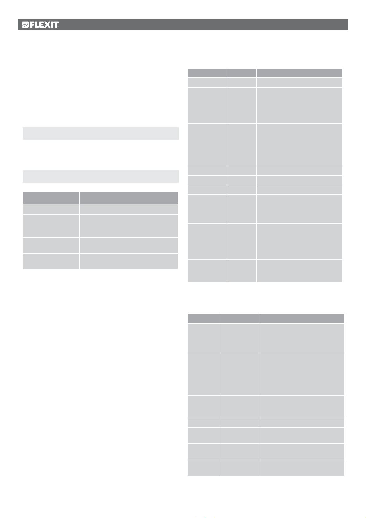
Start page > Main menu > Log in
2.2.4.
Set time/time channels
Start page > Quick menu > Timing program
Parameter Function
Date and Time This is where you set the time and date
Continuous operation This is where you can override the
timing programs and switch the unit to
continuous operation
Current value Displays the current timing
(temperature and speed)
Monday to Sunday See explanation of week schedule
(2.2.4.2)
2.2.4.1.
Set the calendar and timing program
General
This section describes functions and settings for the timing
program and calendars.
When no object with higher priority (for example Manual
control <> Auto) is activated, the system can be switched off
or the steps changed via the timing program. A maximum of
six switch-over times can be specified per day.
The calendar stop overrides the calendar exception, which in
turn overrides the normal timing program (only in operating
mode). Up to 10 periods or exception days can be specified
for each calendar.
NB! Both setpoints for fan steps and temperature setpoints
(comfort /economy) are controlled by the timing program.
2.2.4.2.
Parameter Value Function
Current value --- Switching according to schedule
Monday Shows current command when the
Copy schedule
Tuesday Same function as for Monday
... ...
Sunday Same function as for Monday
Exception Shows current command when the
Period: Start
Period: Start
Period: End
Period: Start
Week schedule
–Mon to
–Tu– Fr
–Tu– Su
current day is Monday. The latest
time that can be entered for a day
is 23:59. Go to the day switching
schedule for Mondays
Copies times for the timing
program from Monday to
Tuesday–Friday/Tuesday–Sunday.
– Passive (no copying).
– Copying starts. Return to the
display screen
current day is an exception day.
Go to the day switching schedule
for exception days
(Only Authority level 3.)
Start date for week schedule.
*,* *.00 means that the week
schedule is always activated. --->
Activate week schedule
(Only Authority level 3.)
Start date and start time for
deactivating week schedule
2.2.4.3.
Parameter Value Function
Current
value
Day
schedule
Time-1 Special case: This time must not
Value-1 Switching command for Time-1
Time-2 Switching time 2
Value-2 ...
Value-6
Time-3 ...
Time-6
Dayschedule
--- Switching according to the
schedule when the current
weekday is the same as the
switching day
Status for current week or
exception day:
– Passive
– Active
– Current weekday (system day) is
not the same as the switching day.
– Current weekday (system day) is
the same as the switching day
be changed, and must always be
00:00
*: * ---> Time deactivated
Analogue value 1
Analogue time 2
10
Page 11
2.2.4.4.
Kalender (undantag och stopp)
Exception days can be defined in the calendar. These can
include specific days, periods or weekdays. Exception days
override the weekly schedule.
EXAMPLE: Val-x = Date
Only the time for (start) is relevant.
• -(Start)Date = *,01.01.16
Calendar exceptions
Switching follows the weekly schedule and the exceptions
specified in the day schedule when a switching time is
activated in the calendar exception.
Calendar stop
The system is turned off when the calendar stop is activated.
Parameters:
Start page > Main Menu > Unit > Operating
information > Timing program > Calendar exceptions
Start page > Main Menu > Unit > Operating
information > Timing program > Calendar stops
Parameter Value Function
Current
value
– Passive
– Active
Val-x
– Date
– Interval
– Weekday
– Passive
-(Start)Date – Val-x = interval: Enter the start
-End date Val-x = interval:
-Weekday Val-x = only weekdays: Enter
Shows whether a calendar time
is activated:
– No calendar time activated
– Calendar time activated
Specification of exception type:
– A certain day (e.g. Friday)
– A period (e.g. holiday)
– A certain weekday
– Times are deactivated
This value must always be placed
last, after the date
date for the period
– (Val-x = date: Enter specific
date)
Enter the end date for the period
The end date must be later than
the start date
a weekday
Result: 1 January 2016 is an exception date.
• -(Start)Date = Mo,*.*.00
Every Monday is an exception day
• -(Start)Date = *,*.Even.00
All days in even months (February, April, June, August, etc.)
are exception days.
EXAMPLE: Val-1 = Interval
The times for (Start)Date and End date are adjusted.
• -(Start)Date = *,23.06.16 / -End date = *,12.07.16.
23 June 2016 until end of 12 July 2016 are exception days
(for example holidays).
• -(Start)Date = *,23.12.16 / -End date = *,31.12.16
23–31 December are exception days every year. Time End
date = *,01.01.16 will not work because 1 January comes
before 23 December.
• -(Start)Date = *,23.12.16 / -End date = *,01.01.17.
23 December 2016 up to and including 1 January 2017 are
exception days.
• -(Start)Date = *,*.*.17 / -End date = *,*.*.17
Warning! This means that the exception is always active!
The system is constantly in exception mode or turned off.
EXAMPLE: Val-1 = Weekday
Val-1 = Weekday
The times for weekdays are adjusted.
• Weekday = *,Fr,*
Every Friday is an exception day.
• Weekday = *,Fr,Even
Every Friday in even months (February, April, June, August,
etc.) is an exception day.
• Weekday = *,*,*
Warning! This means that the exception is always active!
The system is constantly in exception mode or turned off.
11
Page 12
2.3. Adjust the setpoints for speeds and
temperatures
Start page > Quick menu > Setpoints/Settings
Parameter Function
All settings >
Timing program >
Setp.comf.heat Indicates the temperature setpoint
Setp.econ.heat Indicates the temperature setpoint
Setp.TF step 1 Indicates the supply air flow
Setp.TF step 2 Indicates the supply air flow
Setp.TF step 3 Indicates the supply air flow
Setp.FF step 1 Indicates the extract air flow
Setp.FF step 2 Indicates the extract air flow
To adjust supply air temperature limits with extract air regulation.
Start page > Quick menu > Setpoints/Settings
Parameter Function
Setpoint, min. supply
air temp.
Setpoint, max. supply
air temp.
Indicates the lowest permitted supply air
temperature
Indicates the highest permitted supply
air temperature
2.6. Change the unit for the flow display
Toggles between m3/h and l/s in the air flow rate display.
Start page > Main menu > Configuration >
Configuration 2 > Flow display
Setp.FF step 3 Indicates the extract air flow
2.4. Service switch
The service switch is used to stop the unit for service.
Start page > SERVICE SWITCH
Parameter Function
Auto The unit is controlled via time channel
Off Service mode, unit stopped
2.5. Extract air regulation
The unit is configured by default to regulate temperature via
the supply air. However, it can be reconfigured to regulate
via the extract air. To do this, go to the following menu:
Start page > Main menu > Configuration >
Configuration 1 > Temperature regulation type
Parameter Function
Supply air Temperature regulation is controlled by
the supply air temperature
Extract air Temperature regulation is controlled by
the extract air temperature
After making a change in a configuration menu, a restart is
required.
Parameter Function
No Not used.
l/s Displays flow in l/s
3
/h Displays flow in m3/h
m
After making a change in a configuration menu, a restart is
required.
Start page > Main menu > Configuration >
Configuration 2 > Restart > Execute
RESTART
2.7. Alarm handling
If an alarm has been triggered, it will be shown by the flashing
alarm symbol. You can get more information by pressing the
alarm button. To reset the alarm, press the alarm button twice
and select Confirm/Reset and then Execute in the menu.
Alternatively, the alarm can be reset with the menu option:
Start page > Main menu > Alarm management >
Alarm reset > Execute
Start page > Main menu > Configuration >
Configuration 1 > Restart > Execute
RESTART
12
Page 13
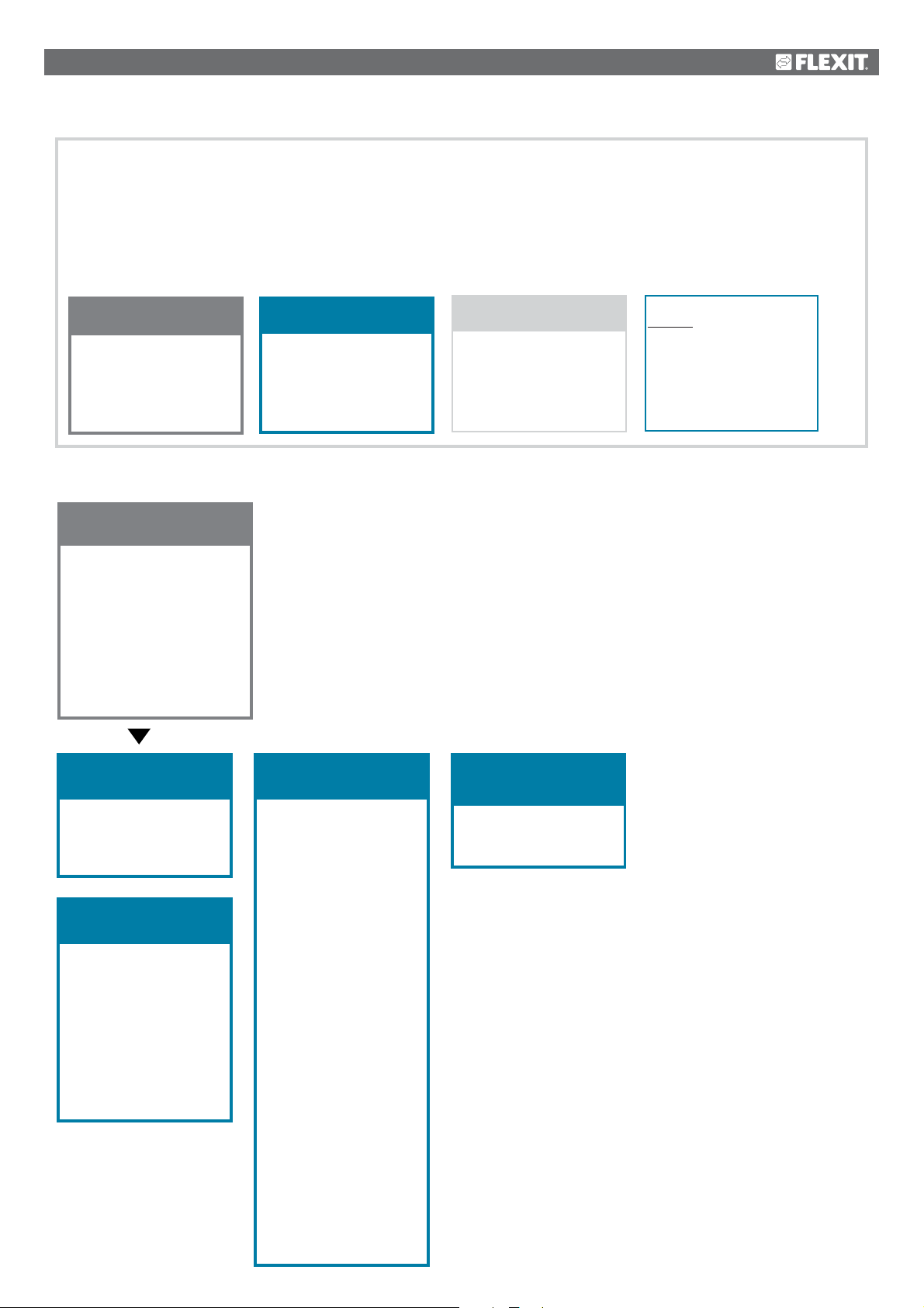
3. Menu tree
Logging in gives you access to several menu options.
The menu tree reflects the default configuration.
It may be different in other configurations.
Level 1
•
Start page
• Quick menu
• Main menu
• Operating information
• SERVICE
SWITCH
Operating mode
Outdoor temperature
Supply air temp.
Extract air temp.
Level 2
•
Level 3
•
Level 4
•
Quick menu
• Language selection
• Timing program
• Setpoints/Settings
Main menu
• Log in
• Unit
• Communication
• General func.
• Alarm handling
• System overview
• Overview of IO config./
raw values
• Configuration
Operating information
• Current operating
mode
• - Alarm
• Timing program
• Outdoor temp.
• Extract air temp.
• Supply air temp.
• Outdoor air damper
• Exhaust air damper
• Current fan step
• Current setpoint SF
• Current actual
value SF
• Supply air fan
• Supply air flow
• Current setpoint FF
• Current actual
value EF
• Extract air fan
• Extract air flow
Current actual
value temperature
• Supply air
• Current setpoint
heating
• Recovery
SERVICE SWITCH
• Auto/Off
Save/Cancel
13
Page 14
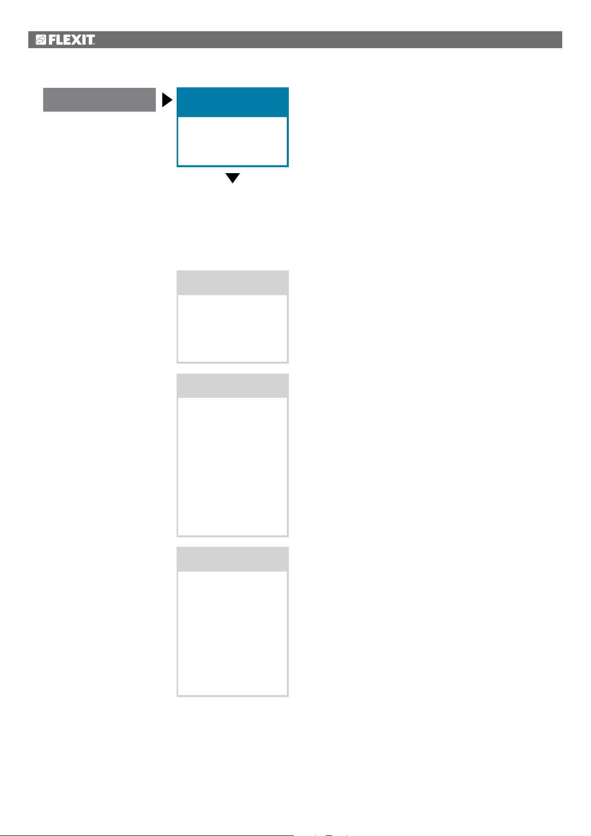
Start page
Quick menu
• Language selection
• Timing program
• Setpoints/Settings
Language selection
• HMI language
+ Alarm snapshot
• Save -> SD
+ Modem
• SMS language
Timing program
Date Time
• Continuous operation
Current value
• Monday
• Copy schedule
• Tuesday
• Wednesday
• Thursday
• Friday
• Saturday
• Sunday
Setpoints/Settings
• All settings
• Timing program
• Setp.comf.heat
• Setp.econ.heat
• Setp.TF step 1
• Setp.TF step 2
• Setp.TF step 3
• Setp.FF step 1
• Setp.FF step 2
• Setp.FF step 3
14
Page 15

Start page
Main menu
• Log in
• Unit
• Communication
• General func.
• Alarm handling
• System overview
• Overview of IO config./
raw values
• Configuration
Log in
• Password
Unit
• Operating information
• Inputs
• Outputs
• Operating functions
• Setpoints/Settings
• Damper control
• Fan control
• Temperature regulation
• Regulators
• Operating time
Communication
• Comm. modules
• Process bus
• TCP/IP
• Climatix IC
• Modbus
• Modem
• SMS
• Restart
General func.
• Summer/winter mode
• Manual operation
• Activate manual alarm
• Activate comm. test
• Communication test
• Set IO to
• Alarm Snapshot
• Snapshot memory full
• Trend archiving
• Trend archive export
• Trend archive full
Alarm handling
• Alarm reset
Danger (A)
High (A)
Low (B)
Warning (C)
• Alarm output selection
• Alarm output 1
• Modbus alarm
• Process bus comm.
• IO exp. bus
• Comm. module 1
- Communication error
- Status
• Comm. module 2
- Communication error
- Status
• Comm. module 3
- Communication error
- Status
System overview
• Date Time
• Communication
• Application info.
• Versions
• Save/Reset
• Diagnosis
• Trend archiving
• Alarm Snapshot
• Password
administration
• HMI
• Language selection
Overview of IO
config./raw values
• Temperatures
• Pressure/Flows
• Digital inputs
• Digital alarm
• Damper outputs
• Fan outputs
• Temp. control outputs
• Alarm outputs
Configuration
• Configuration 1
• Configuration 2
• Config. lnputs/Outputs
• IO config. control
Duplicated
Not configured
• Set IO to
• Overview, Outputs
• Inputs
• Integrations
15
Page 16
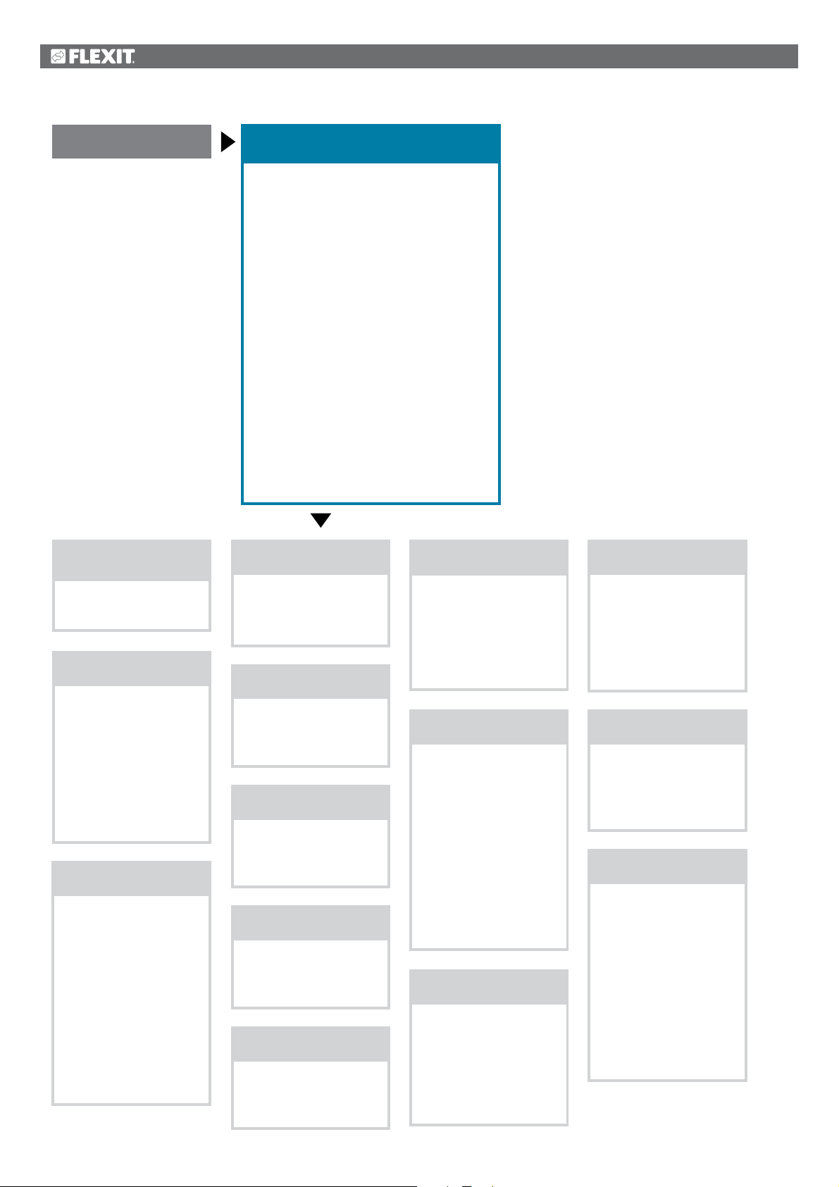
Start page
Operating information
• Current operating mode
• - Alarm
• Timing program
• Outdoor temp.
• Extract air temp.
• Supply air temp.
• Outdoor air damper
• Exhaust air damper
• Current fan step
• Current setpoint SF
• Current actual value SF
• Supply air fan
• Supply air flow
• Current setpoint EF
• Current actual value EF
• Extract air fan
• Extract air flow
Current actual value, temperature
• Supply air
• Current setpoint, heating
• Recovery
Current operating
mode
• Auto/Off
Save/Cancel
- Alarm
• Current
• Operating status
• SERVICE SWITCH
• Continuous operation
• Timing program
• From BMS
• External control
• Power up delay
Timing program
Current value
• Monday
• Copy schedule
• Tuesday
• Wednesday
• Thursday
• Friday
• Saturday
• Sunday
• Calendar exception
• Exception
• Calendar stop
Outdoor temp.
• Supply air
• Outside
• Extract air
Extract air temp.
• Supply air
• Outside
• Extract air
Supply air temp.
• Supply air
• Outside
• Extract air
Outdoor air damper
• Outdoor air damper
• Exhaust air damper
• Open time
Exhaust air damper
• Outdoor air damper
• Exhaust air damper
• Open time
Current fan step
• Supply air fan
• Extract air fan
Current fan step
• Block high speed
• Setting, operating
time
Current setpoint SF
Current fan step
Current setpoint
supply air
• Step 1
• Step 2
• Step 3
• Max. forced ventilation
• Min. operating time
• Power up delay
• Deviation alarm
• Ext. setpoint
function SF
Current actual value SF
Current value
• Regulator
• Output signal
• Operation
• Alarm
• Setpoints/Settings
Supply air fan
Current value
• Regulator
• Output signal
• Operation
• Alarm
• Setpoints/Settings
Supply air flow
• Supply air flow
• Extract air flow
• Supply air filter
• Extract air filter
Current setpoint EF
Current fan step
Current setpoint
extract air
• Step 1
• Step 2
• Step 3
• Max. forced ventilation
• Min. operating time
• Deviation alarm
• Ext. setpoint
function EF
16
Page 17
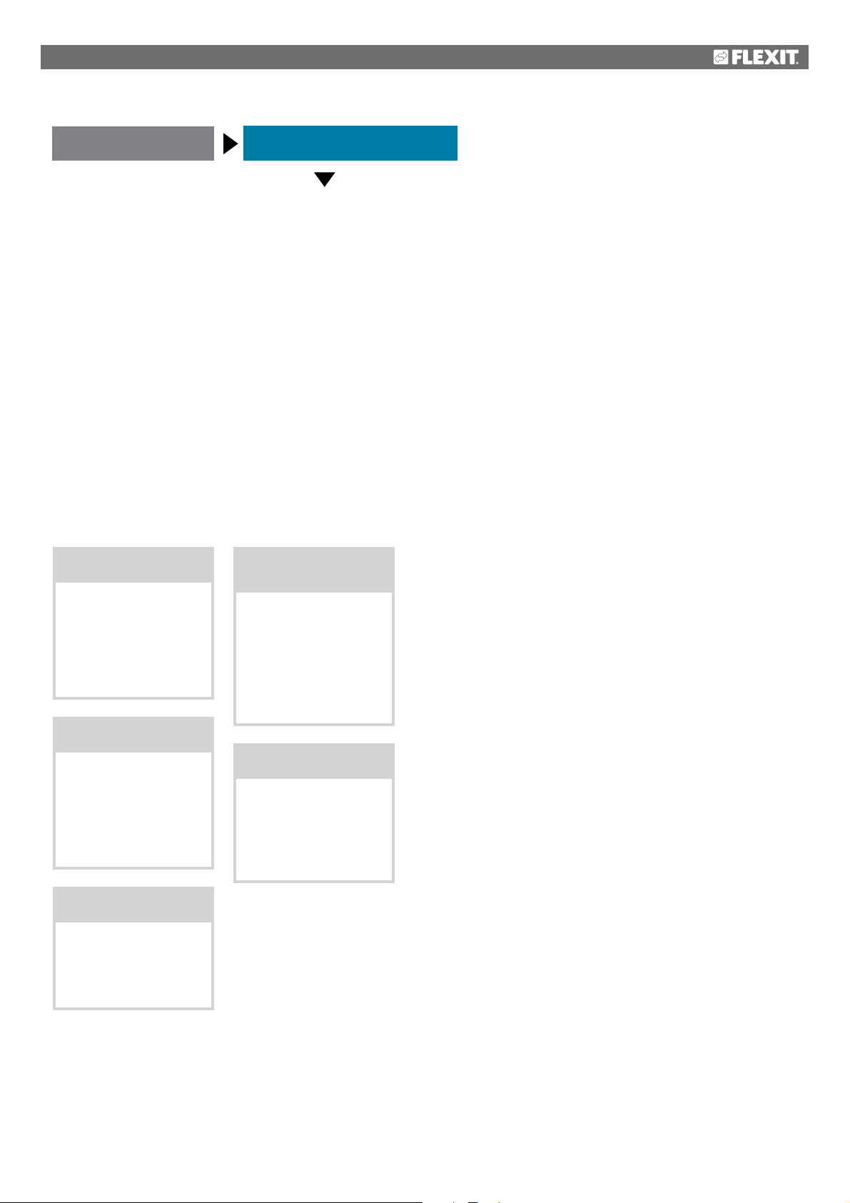
Start page
Operating information, cont.
Current actual value EF
Current value
• Regulator
• Output signal
• Operation
• Alarm
• Setpoints/Settings
Extract air fan
Current value
• Regulator
• Outdoor signal
• Operation
• Alarm
• Setpoints/Settings
Extract air flow
• Supply air flow
• Extract air flow
• Supply air filter
• Extract air filter
Current setpoint,
heating
Current actual value
temperature
Supply air
Current setpoint
heating
• Comfort heating
• Economy heating
Recovery
• Regulator
• Output signal
• Alarm
• Start time
• Start temp.
17
Page 18
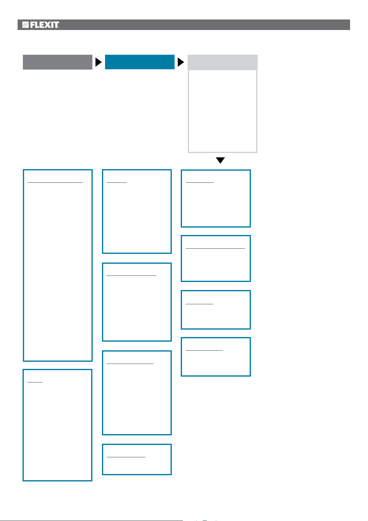
Start page
Main menu
Unit
• Operating information
• Inputs
• Outputs
• Operating functions
• Setpoints/Settings
• Damper control
• Fan control
• Temperature
regulation
• Regulators
• Operating time
Operating information
• Current operating
mode
• - Alarm
• Timing program
• Outdoor temp.
• Extract air temp.
• Supply air temp.
• Outdoor air damper
• Exhaust air damper
• Current fan step
• Current setpoint SF
• Current actual
value SF
• Supply air fan
• Supply air flow
• Current setpoint EF
• Current actual
value EF
• Extract air fan
• Extract air flow
Current actual
value temperature
Supply air
• Current setpoint
heating
• Recovery
Inputs
+Temperatures
• Extract air
• Supply air
• Outside
+Pressure/Flows
• Supply air flow
• Extract air flow
• Supply air filter
• Extract air filter
+Digital alarm
• Supply air fan
• Extract air fan
• Recovery alarm
• Digital inputs
Outputs
+Digital outputs
• Supply air fan
• Extract air fan
• Outdoor air damper
• Exhaust air damper
• Alarm output 1
+Analogue outputs
• Supply air fan
• Extract air fan
• Recovery
Operating functions
Current
Operating status
• SERVICE SWITCH
• Continuous
Operation
• Timing program
• From BMS
• External control
• Power up delay
Setpoints/Settings
• All settings
• Timing program
• Setp.comf.heat
• Setp.econ.heat
• Setpoint, SF step 1
• Setpoint, SF step 2
• Setpoint, SF step 3
• Setpoint, EF step 1
• Setpoint, EF step 2
• Setpoint, EF step 3
Damper control
• Power down delay
• Damper
Fan control
• Supply air fan
• Extract air fan
Current fan step
• Block high speed
• Setting, operating
time
Temperature regulation
Current actual
temperature value
• Temp. setpoints
• Heat recovery
Regulators
• Supply air fan
• Extract air fan
• Heat recovery
Operating time
• Supply air fan
• Extract air fan
• Settings.fan
18
Page 19
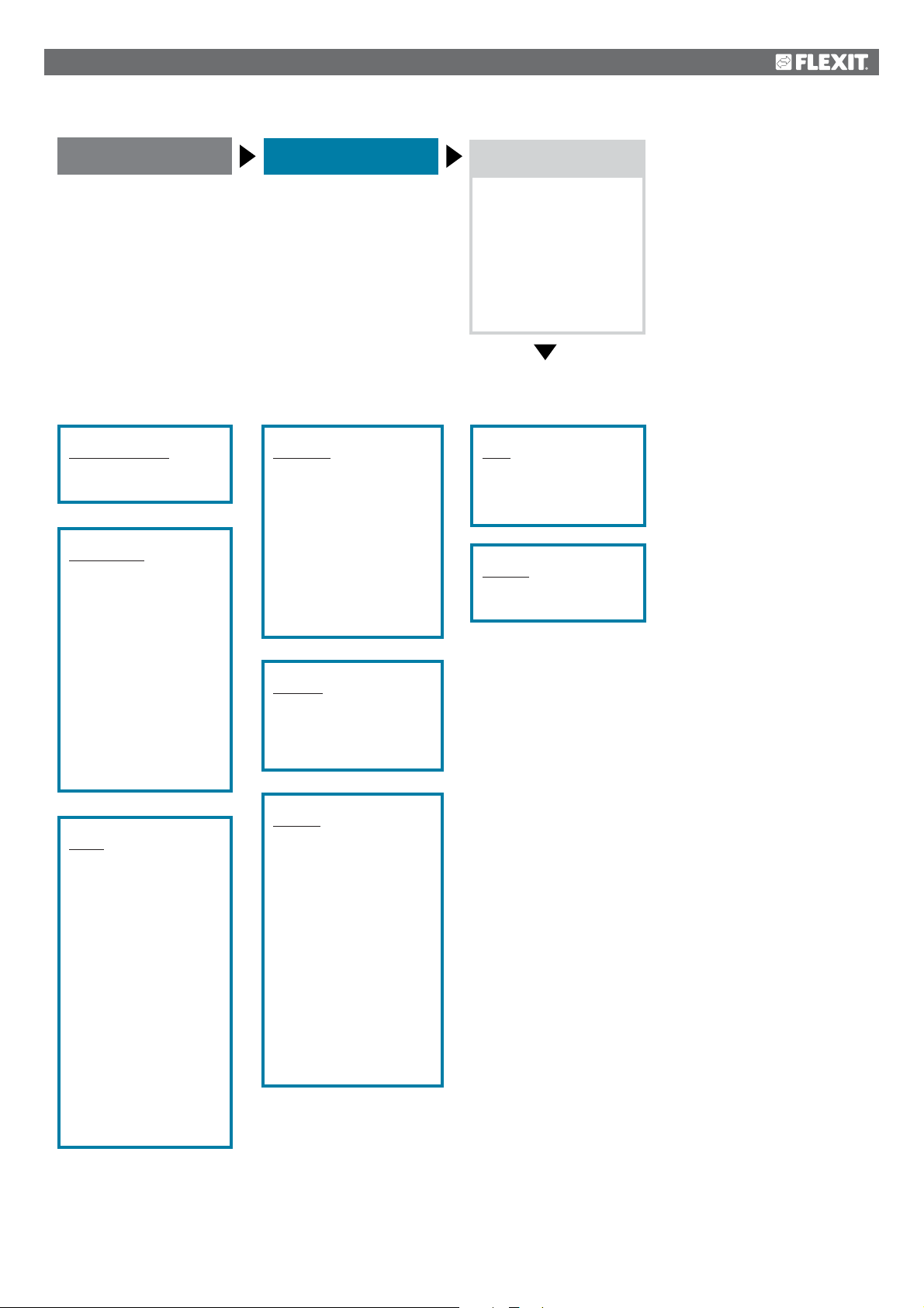
Start page
Main menu
Communication
• Comm. modules
• Process bus
• TCP/IP
• Climatix IC
• Modbus
• Modem
• SMS
• Restart
Comm. modules
• Restart
• Module change
Process bus
• Address set
Current address
• +TCP/IP
• Multi cast
• Port
Status
Error
• Power supply
+Serial number
Unit family
Unit variant
BSP version
• Other settings
TC/IP
• DHCP
Current IP
Current Mask
Current Gateway
• Set IP
• Set Mask
• Set Gateway
• Primary DNS
• Secondary DNS
Name
MAC
Link
100 MB
• Other settings
After value change,
a restart is required
• Restart
Climax IC
• Activate
Serial number
+Status
Communication
Cloud server
Distributor
• Upgrade permitted
Upgrade requested
• Other settings
• System info
Modbus
• Comm. failure
+Internal settings
• RS485
• TCP/IP
Modem
Modem connected
+Status
Signal strength (GSM)
• PIN
• +Tel. no. 1
• +Tel. no. 2
• +Tel. no. 3
• +Tel. no. 4
• +SMS
• Active no.
• Language
• On alarm reset
Send string
Receive string
• Other settings
SMS
• Current number
• SMS settings
• Modem settings
Restart
• Execute
Save/Cancel
19
Page 20
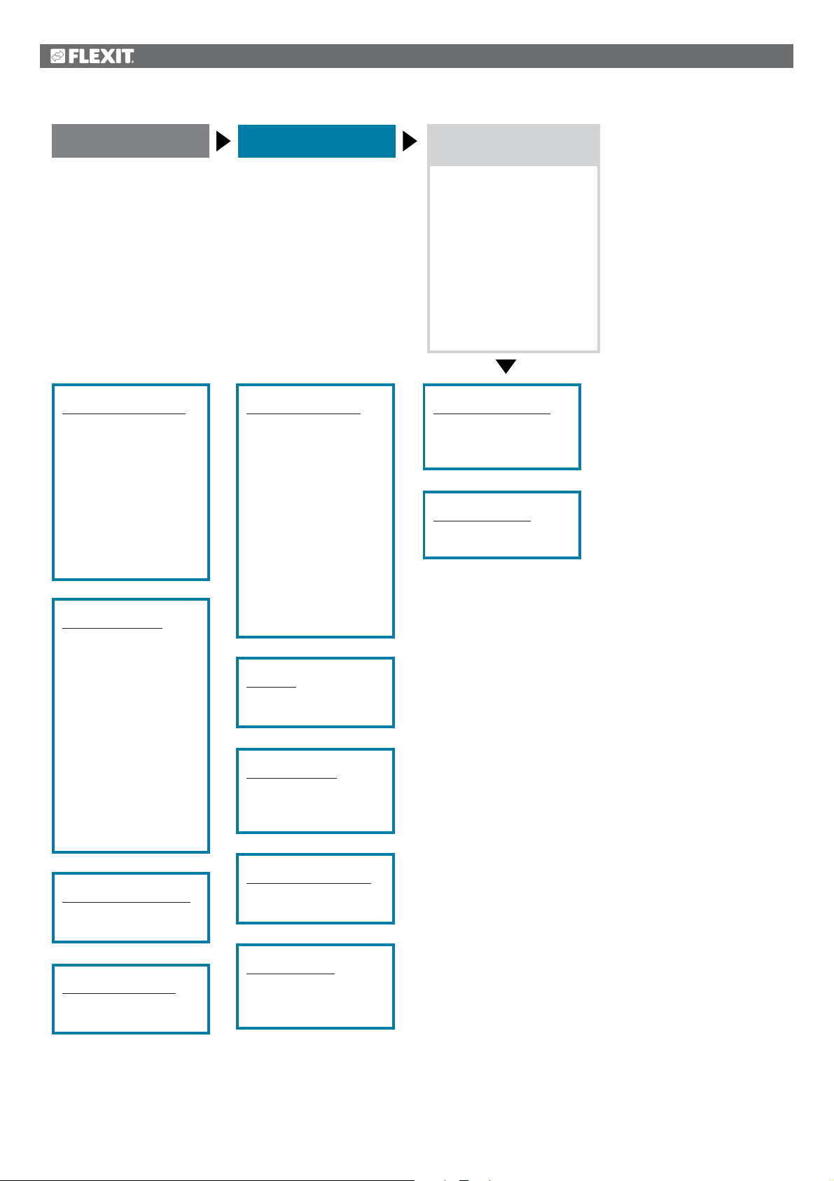
Start page
Main menu
General func.
• Summer/winter mode
• Manual operation
• Activate manual alarm
• Activate comm. test
• Communication test
• Set IO to
• Alarm Snapshot
• Snapshot memory full
• Trend archiving
• Trend archive export
• Trend archive full
Summer/winter mode
Status
Outdoor temperature
reduced
• Date/Time, summer
• Date/Time, winter
• Time constant
• Outdoor temperature,
summer
• Outdoor temperature,
winter
Manual operation
• Manual control
Current value
Alarm
• Alarm configuration
• Alarm class
• Alarm delay
Active priority
• +Operating time,
hours
• Reset
Last reset
Date Time
• Other settings
• Order of priority
Communication test
• Manual control
Current value
Alarm
• Alarm configuration
• Alarm class
• Alarm delay
Active priority
• +Operating time,
hours
• Reset
Last reset
Date Time
• Other settings
• Order of priority
Set IO to
• Line test/Auto
Save/Cancel
Alarm Snapshot
• Inactive/Active/
Export/Zero
Save/Cancel
Trend archive export
• None/Full/Monthly/
Weekly/Now
Save/Cancel
Trend archive full
Last reset
• Other settings
Activate manual alarm
• No/Yes
Save/Cancel
Activate comm. test
• No/Yes
Save/Cancel
Snapshot memory full
Last reset
• Other settings
Trend archiving
• None/System
Operation/Always
Save/Cancel
20
Page 21
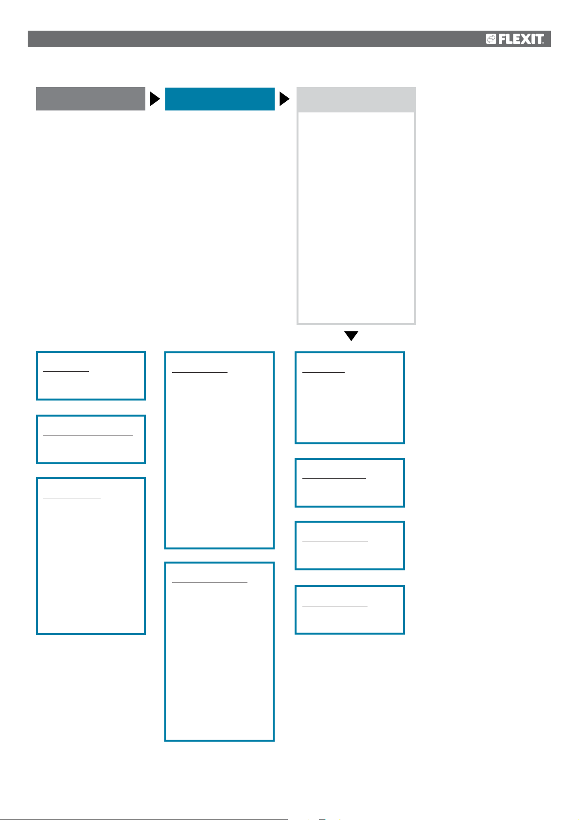
Start page
Main menu
Alarm handling
• Alarm reset
Danger (A)
High (A)
Low (B)
Warning (C)
• Alarm output selection
• Alarm output 1
• Modbus alarm
• Process bus comm.
• IO exp. bus
• Comm. module 1
- Communication error
- Status
• Comm. module 2
- Communication error
- Status
• Comm. module 3
- Communication error
- Status
Alarm reset
• Execute
Save/Cancel
Alarm output selection
• High(A)/H+L(A+B)
Save/Cancel
Alarm output 1
• Manual control
Current value
Error
Active priority
• +Operating time,
hours
• Reset
Last setting
Date Time
• Contact function
• Other settings
• Order of priority
Modbus alarm
• Out of operation
• Current value
Error
Alarm
Step error
• Alarm configuration
• Alarm class
• Alarm delay
• +Operating time,
hours
• Reset
Last reset
Date Time
• Input/output config.
• Contact function
• Other settings
Process bus comm.
• Manual control
Current value
Alarm
• Alarm configuration
• Alarm class
• Alarm delay
Active priority
• +Operating time,
hours
• Reset
Last reset
Date Time
• Other settings
• Order of priority
IO exp. bus
Response time
timeout
Number of retries
Loop time
Update time
• Diagnosis
Comm. module 1
• Restart
• Module change
Comm. module 2
• Restart
• Module change
Comm. module 3
• Restart
• Module change
21
Page 22
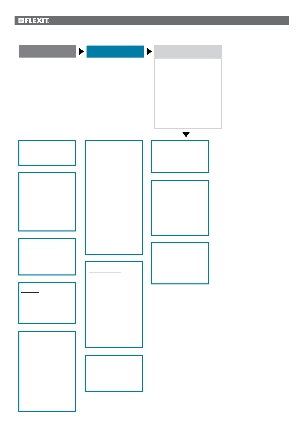
Start page
Main menu
System overview
• Date Time
• Communication
• Application info.
• Versions
• Save/Reset
• Diagnosis
• Trend archiving
• Alarm Snapshot
• Password administration
• HMI
• Language selection
Date Time
• Date/Time
Save/Cancel
Communication
• Comm. modules
• Process bus
• TCP/IP
• Climatix IC
• Modbus
• Modem
• SMS
• Restart
Application info.
Site Name
Street
City
• Other settings
Versions
+System info.
+BSP version
+Process bus
+Serial number
Version
Save/Reset
SD card
• +Save param.->SD
• +Load param. <-S
• Filter
• Restart
• Save snapshot->
• Save trend->SD
• Load BSP/Appl.<-
• Restore operating
settings
• Restore factory settings
• Save operating settings
Diagnosis
• Restart
• Versions
• +Unit name
Serial number
Unit ID
+Number of restarts
• Reset
Cause
Internal temperature
Operating time,
hours
• +Create trace file
Status
+SD card
• Save trace ->SD
• Save param.->S
• Save snapshot->
• Other settings
Trend archiving
Status
Number of current
objects
• Number of
configured objects
• Reconfigure
After valuation,
a restart is required
• Restart
• Activate
• Save trend ->SD
• Delete all data
• Trend archive full
Alarm snapshot
• Records 01-35
• Records 36-70
• Records 71-100
• Other settings
Password administration
• Enter password
• Close account
• Change password
HMI
Temperature (ext.)
• HMI language
• Imp. unit system
• Reset when inactive
• Aut. password (ext.)
• Message time:
integrated
Language selection
• HMI language
+Alarm snapshot
• Save -> SD
+Modem
• SMS language
22
Page 23
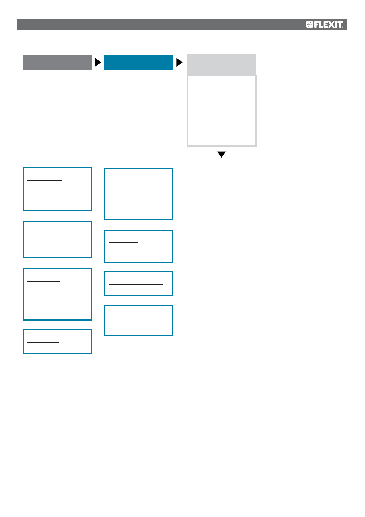
Start page
Main menu
Overview of IO
config./raw values
• Temperatures
• Pressure/Flows
• Digital inputs
• Digital alarm
• Damper outputs
• Fan outputs
• Temp. control
outputs
• Alarm outputs
Temperatures
HV IO:
• Supply air
• Extract air
• Outside
Pressure/Flows
HV IO:
• Supply air filter
• Extract air filter
Digital inputs
HV IO:
• External control
input 1
• External control
input 2
Digital alarm
HV IO:
Damper outputs
HV IO:
• Outdoor air damper
output
• Exhaust air damper
output
Fan outputs
HV IO:
• Supply air fan output 1
Temp. control outputs
HV IO:
Alarm outputs
HV IO:
• Alarm output1
23
Page 24
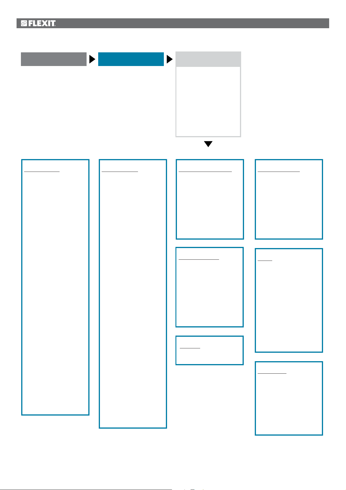
Start page
Main menu
Configuration
• Configuration 1
• Configuration 2
• Konfig.ln-Utgångar
• IO config. control
Duplicated
Not configured
• Set IO to
• Overview, Outputs
• Inputs
• Integrations
Configuration 1
General comment:
• Expansion modules
• Fire alarm
• Filter alarm
• Filter alarm, analogue
• Emergency stop
• Alarm reset input
• SuWi input
• Timing program
function
• Timing program step
• External control input
• Buzzer alarm output
Sensor:
• Temp. room sensor
• Extract air temp.
sensor
• Supply air temp.
sensor
• Outdoor temp. sensor
Functions:
• Damper
• Extract air fan
• Fan regulation type
• Temp. regulation type
• Mixing damper
• Heat recovery
• Heating
• Electric heating
• Cooling
• Extra heating
• Extra electric heating
• Extra cooling
• Fire damper
• Fire fan
• External setpoint
• Configuration 1
• Restart
Configuration 2
• Nighttime cooling
• Support operation
• Boost
• Support operation/
Osstp block
• Damper return
• Dig.step freq.con.
• Flow display
• Fan step type
• Fan alarm
• Fan return
• Fan deviation alarm
• Fan comp. room temp.
• Fan comp. air qual.
• Fan comp. outdoor
temp.
• Fan heating/cooling
• Fan Eng. unit
• Ext. Setpoint, fan
• Ext. setpoint function SF
• Ext. setpoint function EF
• Temp. setpoint type
• Temp. deviation alarm
• Summer/Winter
comp. temp.
• Recovery frost
protection
• Pump/command,
recovery
• Recovery alarm
• Cold recovery
• Recovery efficiency
• AUX input
• AUX temp. sensor
• AUX timing program
• AUX output signal
• AUX operating mode
ind.
• Configuration 2
• Restart
Config. Inputs/Outputs
• Temperatures
• Pressure/Flows
• Digital inputs
• Digital alarm
• Damper outputs
• Fan outputs
• Temp. control outputs
• Alarm outputs
• Config. Inputs/Outputs
• Restart
IO config. control
Non-config.IO
1st non-config.IO no.
Double-config.IO
Double-config.IO
Double-config.IO pos.
Double-config. DO pos.
Number of unused XI
Number of unused DI
Number of unused AO
Number of unused DO
Set IO to
• Line test/Auto
Save/Cancel
Overview, outputs
Analogue outputs
• Supply air fan
• Extract air fan
• Recovery
Digital outputs
• Supply air fan
• Extract air fan
• Outdoor air damper
• Exhaust air damper
• Alarm output 1
Inputs
+Temperatures
• Extract air
• Supply air
• Outside
+Pressure/Flows
• Supply air flow
• Extract air flow
• Supply air filter
• Extract air filter
+Digital alarm
• Supply air fan
• Extract air fan
• Recovery alarm
• Digital inputs
Integrations
• +Room unit
• Settings
• Inputs
• +Energy meter EM24
• Settings
• Inputs
• Flexit MB units
• Settings
• Restart
24
Page 25
4. Backup and program updates
When the system has been fully configured and the
parameters have been set, it can be backed up to an SD
memory card or reset using the data on the memory card.
Two different sets of parameters for a configured system
can be backed up or reset. For example, you can back up
the standard settings (Save factory settings) and adjusted
settings (Save startup settings).
The options below can be selected only with the relevant
authority level. This is done using menu option:
Start page > Main menu > System overview >
Save/Reset
4.2. Load a configuration
Procedure:
1. Insert the memory card into the regulator.
2. Load the values from the memory card.
Start page > Main menu > System overview >
Save/Reset > Load param. <-S = Execute
3. Wait until:
Start page > Main menu > System overview >
Save/Reset > Load param. done = Yes
4. Restart the process unit:
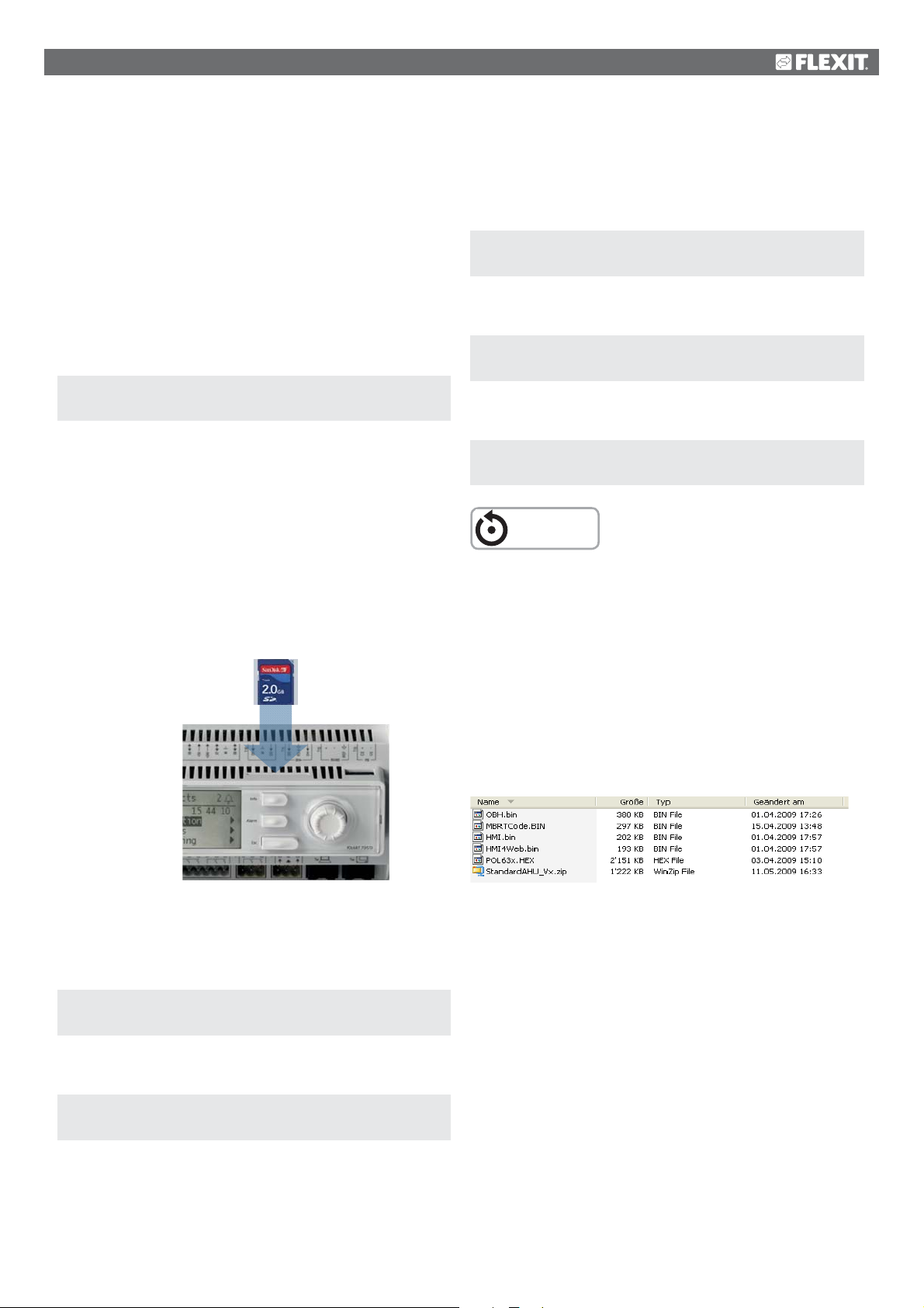
The regulator has a card slot for an SD memory card with
max 2 GB capacity.
4.1. Save a configuration
After initiation and adjustment, the parameters and
configurations can be saved to the SD card. For example,
you can load these values on another process unit with the
same basic configuration (operating system, application,
control panel, HMI4Web and language/communication).
Authority level 4 is required.
Location of SD
memory card
Start page > Main menu > System overview >
Save/Reset > Restart = Execute
RESTART
Standard settings (Factory settings) and adjusted settings
(Startup settings) are handled in the same way.
4.3. Loan an application or software
Preconditions:
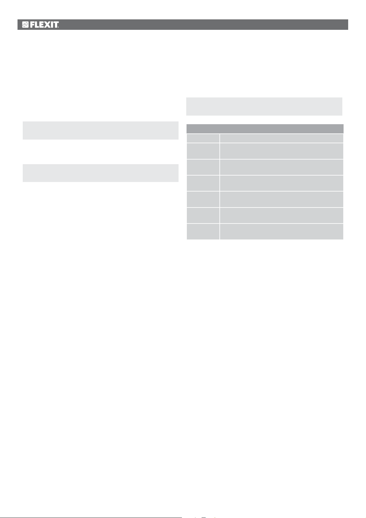
• The (uncompressed) files must be in the root folder of
the SD memory card.
• The files must have the names shown in the screen below.
Files on SD card
Procedure
1. Insert a blank SD memory card into the regulator.
2. Backup the values to the memory card.
Start page > Main menu > System overview >
Save/Reset > Save param.->SD = Execute
3. Wait until:
Start page > Main menu > System overview >
Save/Reset > Save param. done = Yes
Standard settings (Factory settings) and adjusted settings
(Startup settings) are handled in the same way.
Procedure
1. Insert the memory card into the regulator.
2. Switch off the regulator.
3. Press the button in the hole next to the regulator's
status screen with a thin object so that a clicking sound
is heard, and keep the button pressed down.
4. Switch on the regulator.
5. Wait until the LED flashes red and green.
6. Release the button.
7. Wait until orange LED lights up.
8. Switch off the regulator.
9. Switch on the regulator.
25
Page 26
4.4. Error diagnosis - Snapshot
For troubleshooting, the status of the ventilation unit just
before the alarm was triggered can be studied afterwards by
means of export to an SD card. Authority level 4 is required.
Procedure:
1. Insert a blank SD memory card into the regulator.
2. Backup the error diagnosis to the memory card.
5. General functions
Operating modes - Change
The system can be put in different operating modes.
Start page > Main menu > Unit >
Operating functions > Continuous operation
Start page > Main menu > System overview >
Save/Reset > Save snapshot = Execute
3. Wait until:
Start page > Main menu > System overview >
Save/Reset > Save snapshot = Yes
A file has now been generated on the SD card that can be
read from a PC.
Continuous Operation
No The unit operates in timer mode
Econ.St1 The unit operates at ‘Econ’ temperature and
‘Step 1’ speed
Comf.St1 The unit operates at ‘Comf’ temperature and
‘Step 1’ speed
Econ.St2 The unit operates at ‘Econ’ temperature and
‘Step 2’ speed
Comf.St2 The unit operates at ‘Comf’ temperature and
‘Step 2’ speed
Econ.St3 The unit operates at ‘Econ’ temperature and
‘Step 3’ speed
Comf.St3 The unit operates at ‘Comf’ temperature and
‘Step 3’ speed
26
Page 27
6. Configuration
On delivery, the ventilation unit is configured and ready.
Normally, therefore, no adjustments need to be made to the configuration.
However, the addition of accessories and other equipment may require a change to the configuration.
Where necessary, there is a more detailed description in this manual or with the accessory.
This section is, therefore, intended more as general information.
The configuration includes the following four steps:
• Activate and choose type of after heater on circuit board A3
• Configuration 1
• Configuration 2
• Configuration with inputs and outputs
6.1. Configuration 1
If adjustments are needed, ‘Configuration 1’ is the first step in the configuration.
• Configuration is done sequentially, which means that it is not possible to skip any options.
• Configuration 1 must have been completed and the process unit have been restarted before you continue with Configuration 2.
Start:
If necessary: Enter the password for level 3:
Start page > Log in
Then:
Start page > Main menu > Configuration >
Configuration 1
After making a change in a configuration menu, a restart is required.
Start page > Main menu > Configuration >
Configuration 1 > Restart > Execute
NB! The ventilation unit is supplied fully configured
RESTART
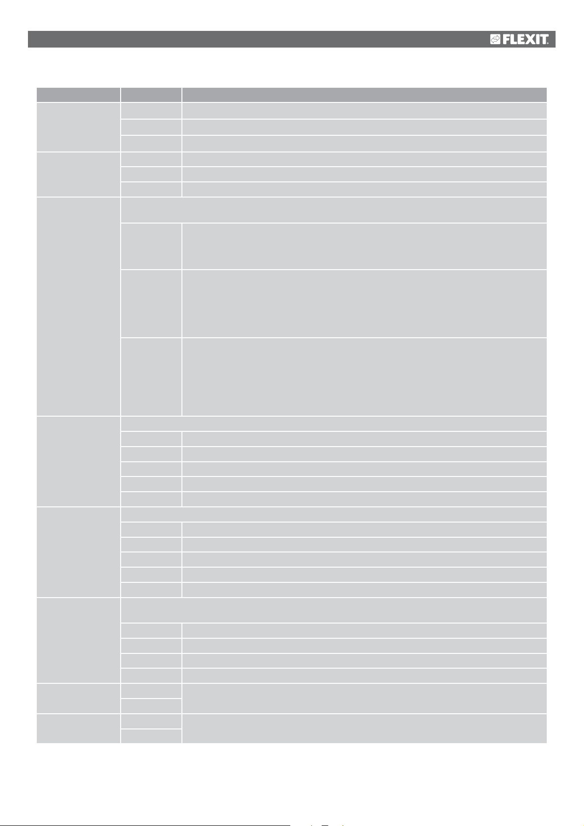
Parameter Value Function
General comment:
Expansion modules No Only the process unit's inputs and outputs are used.
One One expansion module is connected via address 1. Dipswitches 5 and 6 on the module must be set
to On.
Two Two expansion modules are connected via addresses 1 and 2. Dipswitch 5 on module 1 and
dipswitches 4 and 6 on module 2 must be set to On.
Fire alarm No No fire alarm.
Alarm External fire alarm such as smoke detectors, thermostat, fire alarm control centre, etc.
Temp Internal fire alarm via measurement of normal supply air and extract air temperature when both sensors
are accessible. A fire alarm is triggered when one of the two temperatures reaches a specific value.
Alarm+Temp Both fire alarms.
and does not normally need to be changed.
27
Page 28
Parameter Value Function
Filter alarm No No filter alarm.
Comb. Supply air and extract air filter with common alarm input.
Supply air Input only for supply air filter alarm.
Extract air Input only for extract air filter alarm.
Supply+Extract
Filter alarm,
analogue
Emergency stop No Input for emergency stop. If the signal on this input is TRUE, the system is switched off
Alarm reset input No Input for acknowledging or resetting an alarm. Open alarms are acknowledged; closed alarms are
SuWi input No Input for summer/winter switching. If the signal on this input is TRUE, summer compensation is
No No filter alarm.
Supply air Analogue input only for supply air filter alarm.
Extract air Analogue input only for extract air filter alarm.
Supply+Extract
Yes
Yes
Yes
No heating No heating in the summer.
No cooling. No cooling in the winter.
Two separate filter alarm inputs for supply air and extract air filters.
Two separate filter inputs for supply air and extract air filters.
immediately. No alarm is triggered.
reset.
selected.
Timing program
function
Timing program
step
External control
input
Buzzer alarm
output
Sensor:
Both No heating in the summer and no cooling in the winter.
No No timing program.
Step Timing program with possible settings for fan steps (Off and Stx). The parameter Timing program
step determines the number of possible steps.
Step+Temp Timing program with possible settings for fan steps and temperature regulation type (Off, Econ.x
and Comf.x). The parameter Timing program step determines the number of possible steps.
The temperature mode comfort or economy can be selected for each fan step. Comfort and
economy operation have separate setpoints for temperature regulation.
Activation of possible fan steps. This setting controls the number of setpoints for regulated fans.
1 Step Timing program function = Step ---> Possible settings for timing program: Off, St1.
Timing program function = Step+Temp ---> Possible settings for timing program: Off, Econ1, Comf1.
2 Step Timing program function = Step ---> Possible settings for timing program: Off, St1, St2.
Timing program function = Step+Temp ---> Possible settings for timing program: Off, Econ1,
Econ2, Comf1, Comf2.
3 Step Timing program function = Step ---> Possible settings for timing program: Off, St1, St2, St3.
Timing program function = Step+Temp ---> Possible settings for timing program: Off, Econ1,
Econ2, Econ3, Comf1, Comf2, Comf3.
No No external input for operating mode switching, timer, button, detector for external control, etc.
One One input (e.g. on/off).
Two Two inputs (e.g. Auto/Off/St1/St2).
No No alarm output.
One One output (for example for priority alarms).
Two Two outputs (for priority and non-priority alarms).
Sensor 1 Inputs for room temperature sensors. Select max., min., average or individual value for regulation
Sensor 2
Unit 1
Unit 2
for one or more sensors in Configuration 2.
28
Page 29
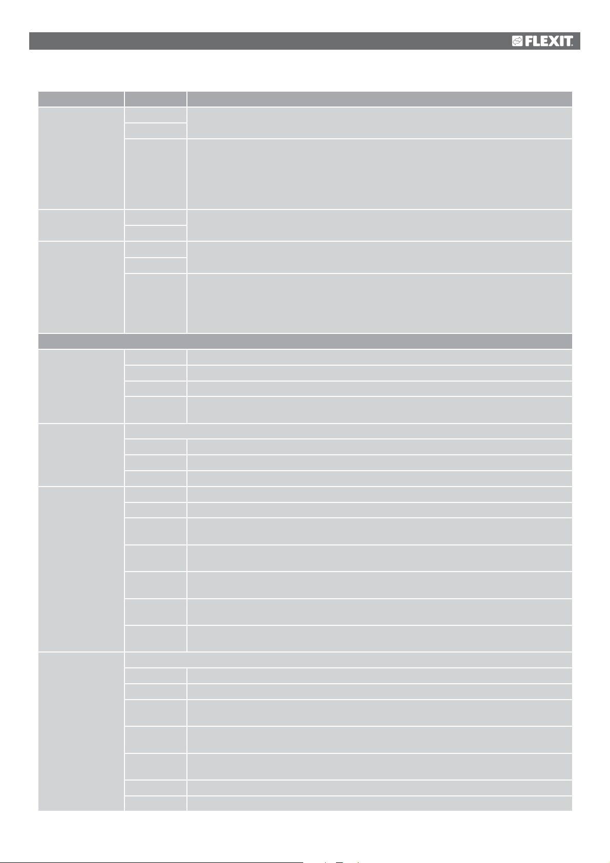
Parameter Value Function
Extract air temp.
sensor
Supply air temp.
sensor
Outdoor temp.
sensor
Functions:
Damper No No air damper.
Extract air fan Extract air fan (supply air fan is always available and cannot be deactivated).
Fan regulation type Direct Up to three digital outputs each for direct-drive fans.
Temp. regulation
type
No Input for extract air sensor.
Yes
Yes+Max If the system has been in operation for more than 5 minutes, the max. temperature is saved when
it is switched off; otherwise the actual temperature is saved.
The setting is meaningful only if there is no room sensor and nighttime operation (for example
nighttime cooling) without a temperature test is to be used. This setting should not be used with
support operation. (Temperature test: the system is started briefly to update the duct sensor
temperature.)
No Input for supply air sensor.
Yes
No Input for sensor for outdoor air temperature.
Yes
Yes+Min. If the system has been in operation for more than 5 minutes, the min. temperature is saved when
it is switched off; otherwise the actual temperature is saved.
The setting is meaningful only if a sensor is fitted in the duct and nighttime support operation
(for example nighttime cooling) is activated, or as a safety function for pump start at low outdoor
air temperatures.
Comb. Two air dampers with a common output.
Outside Outdoor air damper, one output.
Outdoor+
Extract air
None No extract air fan.
Separate Extract air fan with separate output.
Comb. Extract air and supply air fans with common output.
Dir.fro Up to three digital outputs each for frequency-regulated fans with fixed steps.
Fixed freq. One digital and analogue output each for frequency-regulated fans regulated via modulating
Pressure reg. One digital and analogue output and one analogue input each for frequency-regulated fans in
Flow reg. One digital and analogue output and one analogue input each for frequency-regulated fans
Supply air fan
slave
Extract air
fan slave
Select the regulation algorithm for temperature regulation.
Supply air Temperature regulation of supply air only.
Room casc. Cascade regulation of room and supply air temperature.
Extract air
casc.
Room SuWi Cascade regulation of room and supply air temperature in summer; regulation of supply air
Extract air
SuWi
Room Room regulation only.
Extract air Temperature regulation of extract air only.
Two dampers with separate outputs.
analogue outputs (e.g. St1 = 2 V, St2 = 5 V, St3 = 8 V).
pressure-regulated systems.
regulated in flow-regulated systems.
One digital and analogue output each and three analogue inputs for frequency-regulated fans in
pressure-regulated systems where the supply air fan is driven depending on the extract air fan.
One digital and analogue output each and three analogue inputs for frequency-regulated fans in
pressure-regulated systems where the extract air fan is driven depending on the supply air fan.
Cascade regulation of extract and supply air temperature.
temperature only in winter.
Cascade regulation of extract and supply air temperature in summer; regulation of supply air
temperature only in winter.
29
Page 30
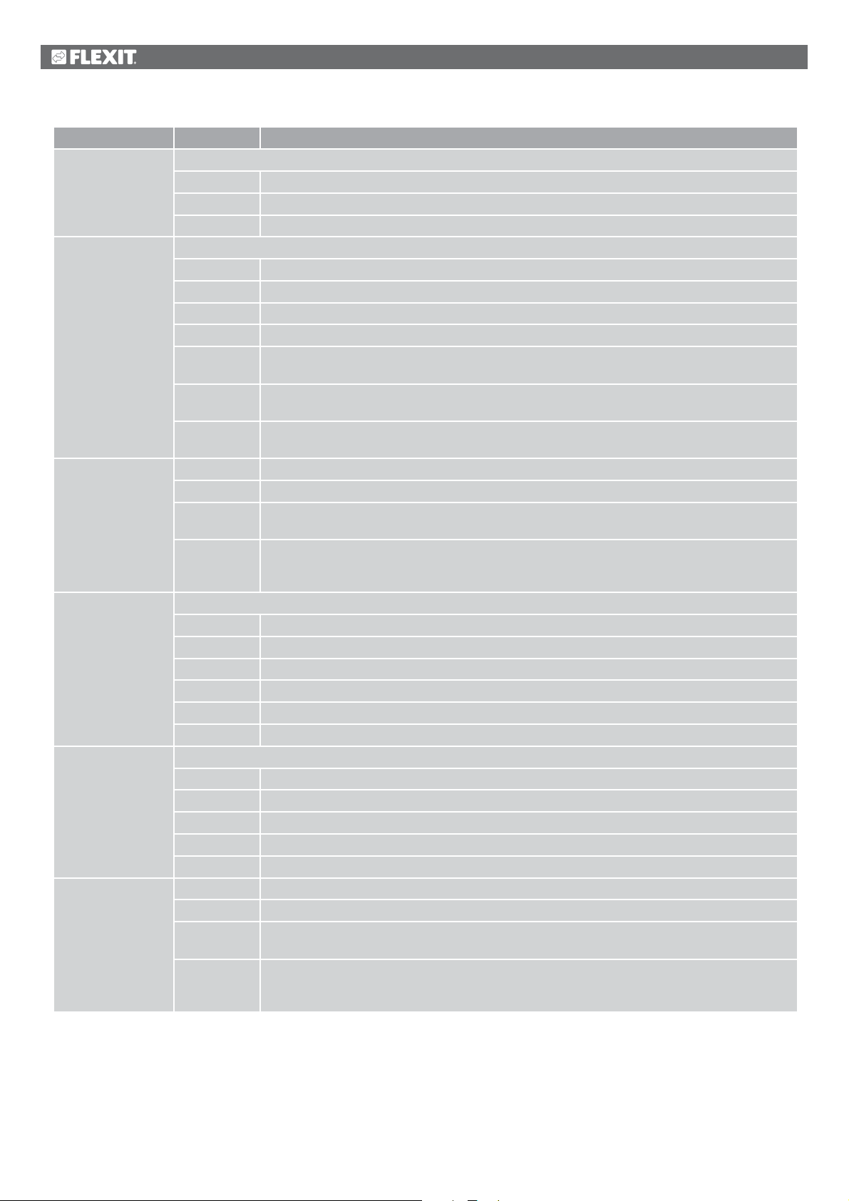
Parameter Value Function
Mixing damper Heat recovery regulation with mixing damper.
No No mixing damper.
Normal Mixing damper with output signal 100% for full circulation.
Inverted Mixing damper with output signal 0% for full circulation.
Heat recovery Select heat recovery regulation with rotating heat exchanger, plate heat exchanger or water heat exchanger.
No No heat recovery.
Rotor Rotating heat exchanger. One analogue output for regulation of rotating heat exchanger.
Plate Plate heat exchanger. One analogue output for regulation of regulating air damper.
Water Water heat exchanger. One analogue output for regulation of the valve.
RotorInv Rotating heat exchanger. One analogue output for regulation of rotating heat exchanger.
Inverted output signal 100% force = 0 V.
PlateInv Plate heat exchanger. One analogue output for regulation of regulating air damper.
Inverted output signal 100% force = 0 V.
WaterInv Water heat exchanger. One analogue output for regulation of the valve.
Inverted output signal 100% force = 0 V.
Heating No No heating circuit.
Yes Heating register without preheating. Analogue heating valve output.
Yes+Preh.
Outdoor temp.
Yes+Preh.Frost
protection
temp.
Electric heating Electric heating register and type of regulation.
No No electric heating register available.
Analogue Electric heating register with regulation via one analogue output.
1Step 1-step electric heating register with regulation via one analogue and one digital output.
2Step 2-step electric heating register with regulation via one analogue and two digital outputs.
3stegBin 3-step electric heating register with binary regulation via one analogue and two digital outputs.
3step3Rel Extra 3-step electric heating register with 3 digital outputs.
Cooling Select cooling register and type of regulation.
No No cooling register.
Water One analogue output for cooling valve output.
DX 1step One analogue and one digital output for 1-step regulation of DX cooling unit.
DX 2step One analogue and two digital outputs for 2-step regulation of DX cooling unit.
DX 3step One analogue and two digital (binary) outputs for 3-step regulation of DX cooling unit.
Extra heating No No extra heating register.
Yes Extra heating register without preheating. Analogue heating valve output.
Yes+Preh.
Outdoor temp.
Yes+Preh.Frost
protection
temp.
Heating register with preheating. Analogue heating valve output.
Heating register with preheating based on frost protection temperature.
Extra heating register with preheating. Analogue heating valve output.
Heating register with preheating based on frost protection temperature.
30
Page 31
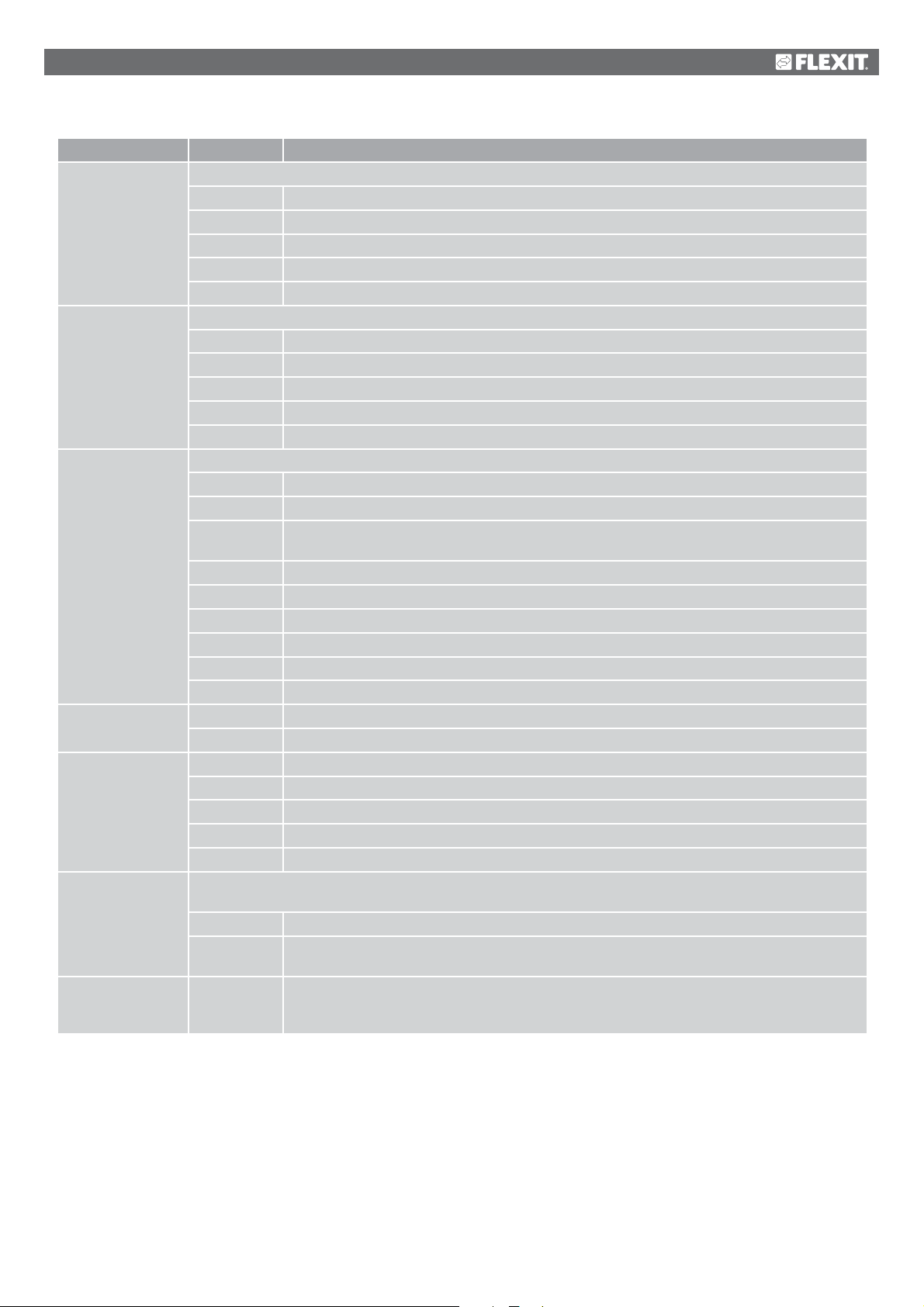
Parameter Value Function
Extra electric
heating
Extra cooling Extra cooling register and type of regulation.
Fire damper Fire damper.
Fire fan No Fire fan control deactivated.
External setpoint No No analogue input for connection of external setpoint or compensation for external setpoint.
Configuration 1 With this parameter, the system is activated after parameter settings have been set, i.e. when Configuration 1,
Restart
Extra electric heating register and type of regulation.
No No extra electric heating register available.
Analogue Extra electric heating register with regulation via one analogue output.
1Step Extra 1-step electric heating register with regulation via one analogue and one digital output.
2Step Extra 2-step electric heating register with regulation via one analogue and two digital outputs.
3stepBin Extra 3-step electric heating register with binary regulation via one analogue and two digital outputs.
No No extra cooling register.
Water One analogue output for extra cooling valve output.
DX 1step One analogue and one digital output for 1-step regulation of extra DX cooling unit.
DX 2step One analogue and two digital outputs for 2-step regulation of extra DX cooling unit.
DX 3step One analogue and two digital (binary) outputs for 3-step regulation of extra DX cooling unit.
No No fire damper.
Yes One digital output and input each for fire damper regulation.
Yes+FollUnit One digital output and input each for fire damper regulation. The fire damper is opened when the
unit starts and closed when the unit stops.
2 Same as ‘Yes’ but with 2 fire dampers.
2+FollUnit Same as ‘Yes+FollUnit’ but with 2 fire dampers.
3 Same as ‘Yes’ but with 3 fire dampers.
3+FollUnit Same as ‘Yes+FollUnit’ but with 3 fire dampers.
4 Same as ‘Yes’ but with 4 fire dampers.
4+FollUnit Same as ‘Yes+FollUnit’ but with 4 fire dampers.
Yes Fire fan control activated.
Volt Input for 0-10 V DC signal.
Ohm Input for 0-2500 ohm signal.
QAA27 Input for QAA27.
BSG21 Input for BSG21 setpoint compensation.
Configuration 2 and Config. Inputs/Outputs have been set (value Ready).
Not ready The system is locked and cannot be started.
Ready The system is unlocked after the parameter settings have been set (value Ready for Configuration
2 and Config.In/Outputs), i.e. the system can be started.
Passive
Execute
The system must be restarted after parameter settings have been set in Configuration 1.
Changed presets in Configuration 2 are implemented.
After restart, the value is changed automatically from Execute to Passive.
31
Page 32
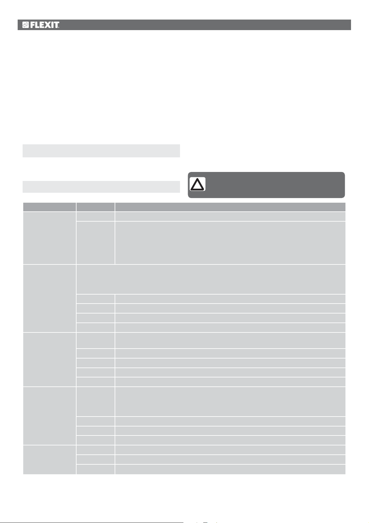
6.2. Configuration 2
If there is a need for adjustments, subfunctions for some parts of the system can be set in Configuration 2.
Preconditions:
Configuration 1 must have been completed, including restart of the regulator.
• Configuration is done sequentially, which means that it is not possible to skip any options.
• Configuration 2 must have been completed, including restart of the process unit, before you continue with Config.In/Outputs.
Start
If necessary: Enter the password for level 3:
Start page > Log in
Then:
NB! The ventilation unit is supplied fully configured
Main menu > Configuration > Configuration 2
Parameter Value Function
Nighttime cooling
Support operation Starts nighttime support operation.
Boost Optimum start of the system with heating and cooling via separate setpoints.
Support operation/
Osstp block
Damper return
No The function is not available.
Yes Free cooling.
Precondition: Nighttime cooling can be selected only if a sensor for outdoor air temperature and
a room or extract air sensor are available.
Temperature motion is activated automatically if only one extract air sensor, which is set to not
hold the values, is available. If the extract air sensor holds the values, the temperature is used to
start nighttime cooling.
Precondition: The function can be selected only if a room or extract air sensor is available.
Temperature motion is activated automatically if only one extract air sensor which holds the values is available.
If the extract air sensor holds the values, the temperature is used for start.
No The function is not available.
Heating The function is available only for heating.
Cooling The function is available only for cooling.
HeatingCooling
No The function is not available.
Heating The function is available only for heating.
Cooling The function is available only for cooling.
HeatingCooling
None No blocking.
Damper Air dampers remain closed.
Dam+Fan Air dampers remain closed and only the supply air fan is started.
No No damper return.
One Return for supply air damper (or common return for both dampers). Digital input for return.
Two Separate return for supply air and extract air dampers. Two digital inputs for return.
The function is available for heating and cooling.
Precondition: The function can be selected only if a room or extract air sensor is available.
The function is available for heating and cooling.
Block the air damper or extract air fan when the system is started optimally or via temperature delta.
NB! This function is intended to be used in an emergency situation.
Warning! A regulating air damper must be in place and be open when the function is selected.
Otherwise, the system may suffer damage.
and does not normally need to be changed.
32
Page 33
Parameter Value Function
Dig.step freq.con. 1 step Digital output for activation of frequency-controlled fans (always activated).
2 step An extra digital output for alternative connection that is dependent on fan step 2.
3 step Two extra digital outputs for alternative connection that is dependent on fan step 3.
Flow display No The function is not available.
l/s Displays flow in litre/second.
3
/h Displays flow in m3/hour.
m
Fan step type Necessary fan regulation output that concerns settings for Fan regulation type, Timing program step and Dig.step
freq.conv.
Separate Digital output for each step.
Example:
Fan regulation type = Direct / Timing program step = 2 / Extract air fan = Yes
---> 4 digital outputs: 2 each for step 1 and step 2, separated for supply air and extract air fans.
Sep.Comb. Separate outputs for the first step, common outputs for subsequent steps.
Example:
Fan regulation type = Pressure reg. / Timing program function = Step+Temp / Timing program step = 3 /
Extract air fan = Yes / Dig.step freq.conv = 3.
---> 4 digital outputs: Step 1 as separate activation of frequency-regulated fans, two extra
outputs that can be used (Dig.step freq.conv) for step 2 and step 3.
Binary The outputs for steps are binarily coded. The setting can be used for Fan regulation type = Direct
or Dir.fro.
Example:
Fan regulation type = Direct / Timing program function = Step+Temp / Timing program step = 3 /
Extract air fan = Yes
---> 4 digital outputs: 2 digital outputs each per fan (Step 1 = DO1 TRUE, Step 2 = DO2 TRUE,
Step 3 = DO1 and DO2 TRUE).
Fan alarm Inputs for fan alarm (e.g. thermojunction). Logical 1 = alarm.
No No alarm.
Comb. Digital input for common alarm.
Supply air Digital input for supply air fan alarm.
Extract air Digital input for extract air fan alarm.
Supply+Extract Two digital inputs for supply air and extract air fan alarms.
Fan return Inputs for operating messages from fans (e.g. pressure current guard or relay contact). Logical 1 = activated fan.
No No return.
Comb. Digital input for common operating messages.
Supply air Digital input for operating messages for supply air fan.
Extract air Digital input for operating messages for extract air fan.
Supply+Extract Two digital inputs for operating messages for supply air and extract air fans.
Fan deviation alarm Setpoint or actual value for monitoring pressure or flow. The alarm is triggered in the event of a deviation that
remains for a certain period of time.
No No monitoring.
Supply air Monitoring of supply air only.
Extract air Monitoring of extract air only.
Supply+Extract Monitoring of supply and extract air.
Room temp. fan
comp.
Air qual. fan comp.
No Room temperature-dependent fan compensation.
Yes
Precondition: Room or extract air sensor activated.
No Air quality-dependent fan compensation. Activation of analogue sensor input.
Yes
33
Page 34
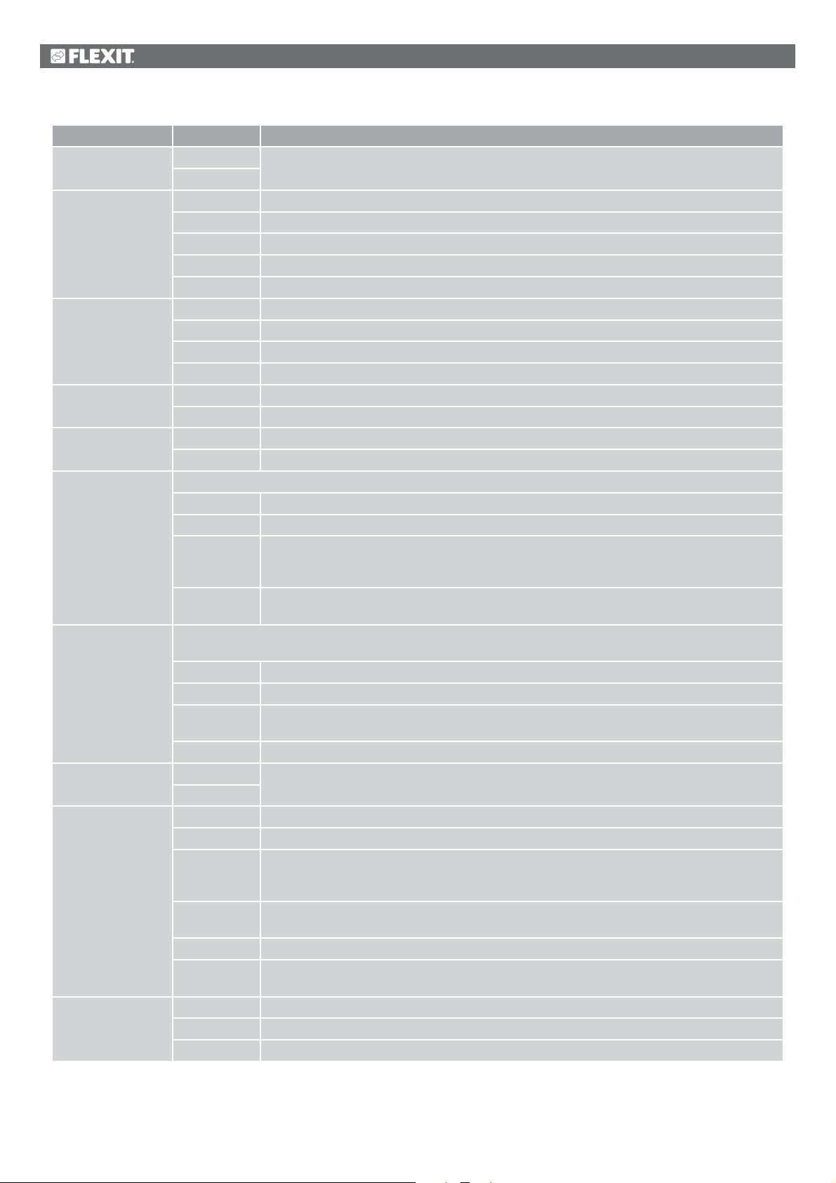
Parameter Value Function
Outdoor temp. fan
comp.
Fan heating/cooling The fan is used as heating or cooling sequence.
Ext. Setpoint, fan No Function deactivated.
Ext. setpoint
function SF
Ext. setpoint
function EF
Temp. setpoint type Predefined settings for temperature setpoints:
Temp. deviation
alarm
Summer/Winter
comp. temp.
Recovery frost
protection
Pump/command,
recovery
No Outdoor air temperature-dependent fan compensation.
Yes
No No sequential fan activation.
Heating Fan activation only in connection with heating sequence.
Cooling Fan activation only in connection with cooling sequence.
HeatingCooling
SF The supply air fan is regulated via an external setpoint.
EF The extract air fan is regulated via an external setpoint.
SF + EF Both the supply air and extract air fans are regulated via an external setpoint.
Comp. Setpoint compensation.
Main Main setpoint.
Comp. Setpoint compensation.
Main Main setpoint.
Heating+Dz Enter heating setpoint and dead zone. Setpoint for cooling = heating setpoint + dead zone.
HeatingCooling
Setpoint+
HalfDz
Cooling Dz Enter setpoint for cooling and dead zone.
Monitors setpoint/current value for temperature.
The alarm is triggered in the event of a deviation that remains for a certain period of time.
No No monitoring
Supply air Monitoring of supply air only.
Room/Extract
air
Supply+Room Monitoring of supply air and room temperature.
No Summer/winter compensation of temperature setpoint.
Yes
No No frost protection for heat recovery.
Guard Frost protection via guard. Digital input for frost guard.
Temp. Frost protection via sensor. One analogue input for regulated frost protection via setpoint.
Temp+Guard Frost protection via sensor and guard. One analogue input for regulated frost protection and one
Pressure Frost protection via pressure sensor. One analogue input for regulated frost protection via setpoint.
Pressure+
Guard
No No pump.
Yes Pump without.
Yes+Motion The extract air fan is regulated via an external setpoint.
Precondition: Outdoor air sensor activated.
Fan activation in connection with both sequences.
Setpoints for heating and cooling are entered directly.
Enter base setpoint and dead zone.
Heating setpoint = base setpoint – half dead zone.
Setpoint for cooling = base setpoint + half dead zone.
Heating setpoint = setpoint for cooling – dead zone.
Room and extract air temperature.
Precondition: Sensor for outdoor air temperature must be available.
Rotating heat exchanger and plate heat exchanger: extract air sensor, water heat exchanger:
water sensor.
digital input for frost guard.
Frost protection via pressure sensor and guard. One analogue input for regulated frost
protection and one digital input for frost guard.
34
Page 35
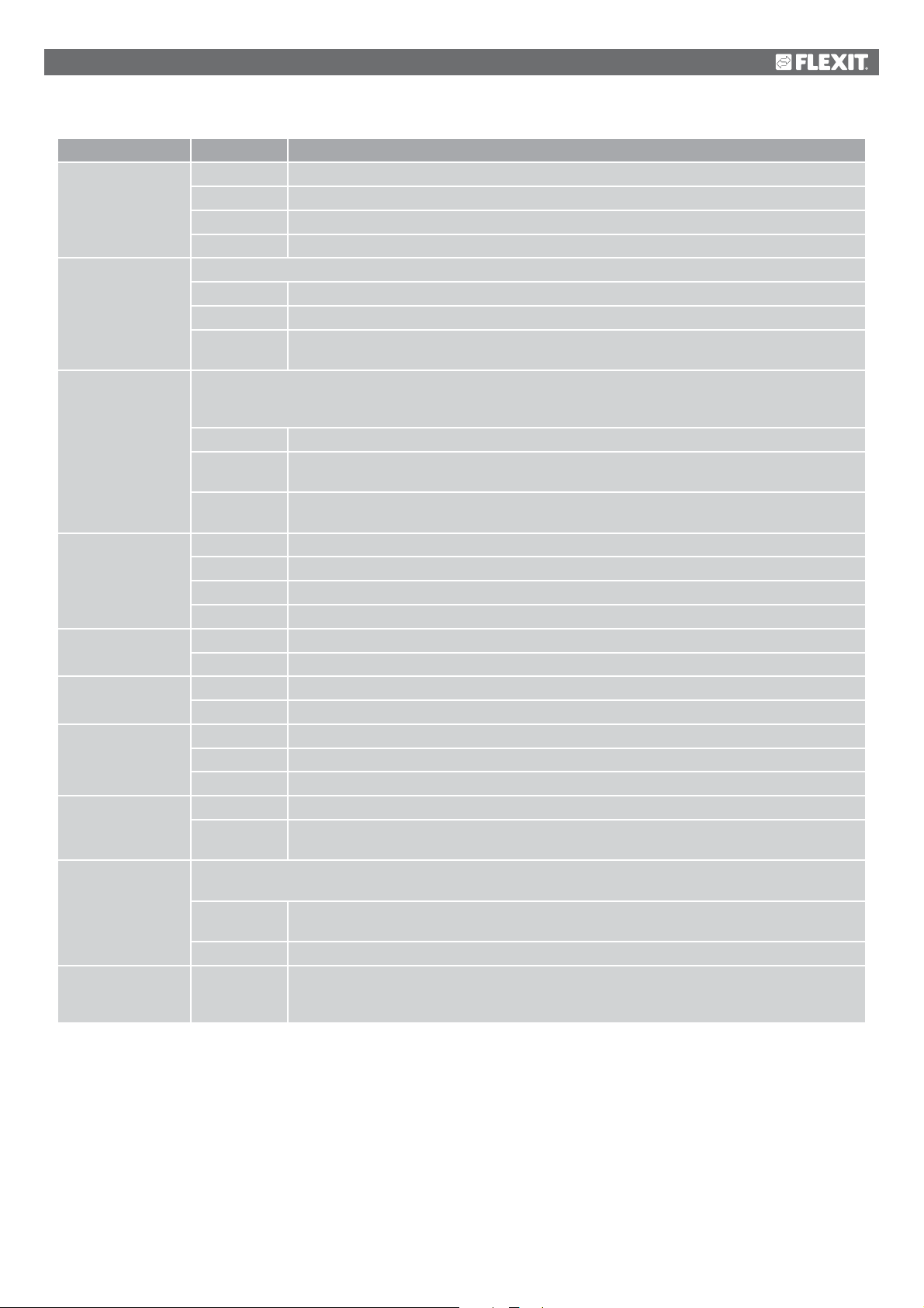
Parameter Value Function
Recovery alarm No No alarm.
Alarm Alarm: activation of one digital alarm input: Logical 1 = alarm.
Return. Return signal. A digital input for return. Pulse in connection with operation.
Alarm+Return Pump with alarm and return. Two digital inputs for pump alarm and return.
Cold recovery Type of cold recovery.
No No cold recovery.
Temp Cooling recovery via difference between outdoor and indoor temperatures.
Outdoor
enthalpy
Recovery efficiency Calculation of heat recovery efficiency.
Precondition: Heat recovery (e.g. rotating heat exchanger) must be activated and there must be a sensor for
both outdoor air temperature and extract air.
No No calculation of heat recovery efficiency.
Exhaust air For calculation with extract air sensor:
Supply air For calculation with the supply air sensor located immediately behind the heat exchanger:
Aux. input
Aux. temp. sensor
Aux. timing program
Aux. output signal No No extra analogue output.
Aux. operating mode
input
Configuration 2 With this parameter, the system is activated after parameter settings have been set, i.e. when Configuration 1,
Restart Execute
No No aux input.
Input Extra digital input for display only.
Alarm Extra digital input with alarm.
Inp.+Alarm Two extra digital inputs; one for display and one with alarm.
No No extra analogue input.
Yes Extra analogue input for connection of temperature display.
No No extra digital output.
Yes One digital aux. output with separate timing program.
Fan Analogue output that generates a 0-10 V signal, depending on current fan step.
Flow device Analogue output that generates a 0-10 V signal, depending on temperature.
No No extra digital output.
Yes An extra digital output, the status of which depends on the current operating mode (e.g. Comfort
Configuration 2 and Config. Inputs/Outputs have been set (value Ready).
Ready The system is unlocked after the parameter settings have been set (value Ready for
Not ready The system is locked and cannot be started.
Passive
Cooling recovery via difference between outdoor and indoor enthalpies.
One analogue input for the extract air sensor unless the frost guard has been activated.
One analogue input for extra supply air sensor.
or Off).
Configuration 2 and Config.In/Outputs), i.e. the system can be started.
The system must be restarted after parameter settings have been set in Configuration 2.
Changed presets in Config. Inputs/Outputs are applied.
After restart, the value is changed automatically from Execute to Passive.
35
Page 36
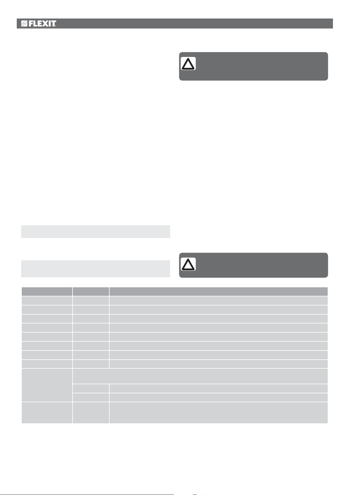
6.3. Configuration of inputs and outputs
If there is a need for adjustments, subfunctions for some parts
of the system can be set in Configuration 1, Configuration 2
and Configuration of inputs and outputs.
In Config.In/Outputs, a physical location is assigned to the inputs
and outputs specified in Configuration 1 and Configuration 2.
Parameter settings are also set for the relevant sensor
conversion (e.g. Ni1000, Pt1000, 0-10 V = 0-1,000 Pa).
Positions in regulator and expansion modules
•
Regulator: All single-digit positions, for example X1.
• Modbus extender: xxxxx
• Expansion module 1: All positions X1x, DI1x, DO1x, AO1x,
for example X11, DO14.
• Expansion module 2: All positions X2x, DI2x, DO2x, AO2x,
for example X21, DO24.
Preconditions
Configuration 1 and Configuration 2 must be ready (the process
unit must be restarted after each configuration).
Start
If necessary: Enter the password for level 3:
NB! The ventilation unit is supplied fully configured
and does not normally need to be changed.
Start page > Log in
Then:
Start page > Main menu > Configuration >
Config. lnputs/Outputs
Parameter Value Function
Temperatures Go to the hardware configuration page for all temperature sensors.
Pressure/Flows Go to the hardware configuration page for all pressure and flow sensors.
Digital inputs Go to the hardware configuration page for all digital inputs without alarm function.
Digital alarm Go to the hardware configuration page for all digital inputs with alarm function.
Damper outputs Go to the hardware configuration page for supply air, extract air and fire dampers.
Fan outputs Go to the hardware configuration page for fans.
Temp. control outputs
Alarm outputs Go to the hardware configuration page for both alarm outputs.
Config. lnputs/
Outputs
Restart Passive
Activation of the system after parameter settings have been set, i.e. when Configuration 1, Configuration 2 and
Config. Inputs/Outputs have been set (value Ready).
Ready The system is unlocked after the parameter settings have been set and can be started.
Not ready The system is locked and cannot be started.
Execute
Go to the hardware configuration page for heating, cooling, heat recovery, etc.
The system must be restarted after parameter settings have been set in Config. Inputs/Outputs.
Changed presets in Config.In/Outputs are implemented. After restart, the value is automatically
changed back.
NB! The inputs and outputs in the expansion
modules can be used if the module has been
activated in Configuration 1.
36
Page 37
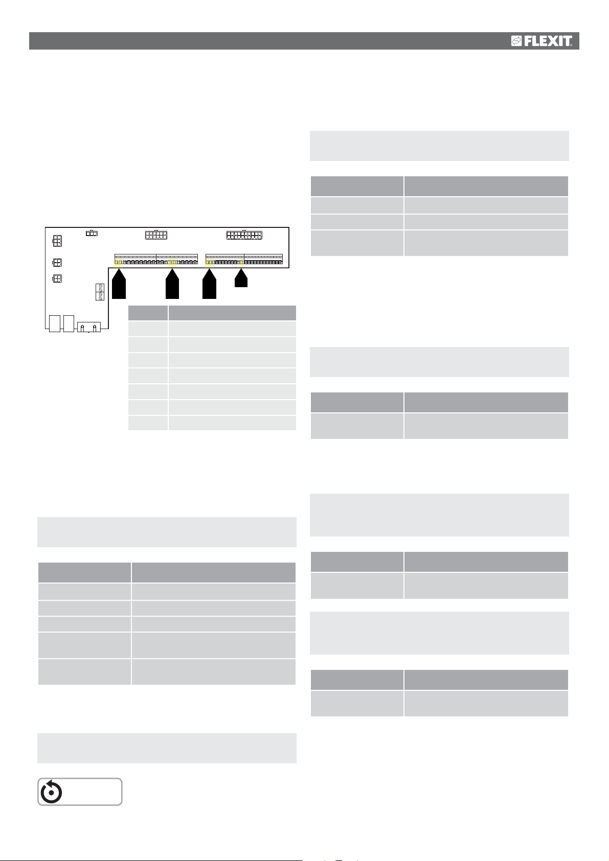
7. Cooling
21 22 23
DX cooling one step or liquid
The unit is equipped by default to control liquid cooling or
one DX step. If another two steps are required, expansion
module SP90 must be installed. Cooling control according
to the following instructions.
7.1. Installation
7.3. For activation of circulation pump
(only applies to liquid cooling)
Start page > Main menu > Configuration >
Configuration 2 > Pump/cooling
Parameter Function
No Pump control deactivated
12 7
4
2
5
3
6
123
4
123
4
1312
P6
P7
P5
P4
1 2 3 4 5
1 2 3 4 5 6 7 8 9
1 2
1
P14
2
P1P3 P2
829310411
16
5 623144155978
P8
10 11 12 13 14 15 16 17 18 19 20
14 15
14
15
Block no.
1L
Function
20 11
12131819 1617
110
P9
P12P10
21 22 23 24 25 26 27 28 29 30 31 32 33 34 35 36 37 38 39 40 41 42 43 44
21
32
32
22
2N
14 DX cooling/cooling pump IN
15 DX cooling/cooling pump OUT
21 Cooling - 0-10 V [AO]
22 Cooling - G0
32 +24 V supply
7.2. Configuration - Cooling control
Now use the control panel to configure the unit for DX
cooling control or liquid.
Start page > Main menu > Configuration >
Configuration 1 > Cooling
Yes Pump control activated
Yes + Motion Pump control activated +
maintenance operation
To perform parameter settings, use the menus below via the
control panel.
7.4. Blocking in connection with outdoor
temperature
Start page > Main menu > Unit > Temperature regulation >
Cooling > Block in connection with outdoor temperature
Parameter Function
-64.0 to 64.0 Indicates the lowest permitted outdoor
temperature for cooling operation
7.5. Operating times (only applies to
DX cooling)
Start page > Main menu > Unit >
Temperature regulation > Cooling >
Direct expansion > Min. operating time
Parameter Function
No Cooling control deactivated
Water Cooling control via liquid battery
DX 1step Cooling control via DX machine, one step
DX 2step Cooling control via DX machine, two
steps, requires expansion module SP90
DX 3step Cooling control via DX machine, three
steps, requires expansion module SP90
After making a change in a configuration menu, a restart is
required.
Start page > Main menu > Configuration >
Configuration 1 > Restart > Execute
RESTART
Parameter Function
0 to 3,600 Indicates the minimum OPERATING TIME
of the DX machine after start
Start page > Main menu > Unit >
Temperature regulation > Cooling >
Direct expansion > Min. idle time
Parameter Function
5 to 600 Indicates the minimum IDLE TIME of the
DX machine after stop
37
Page 38
7.6. Cooling restriction depending on fan
speed (only applies to DX cooling)
8. Temperature regulation
Start page > Main menu > Unit > Temperature
regulation > Cooling > Max. signal, fan control
Parameter Function
Fan step 1 > 0-100% Permitted DX cooling output signal when
the unit operates on step 1 or uses the
setpoint for step 1
Fan step 2 > 0-100% Permitted DX cooling output signal when
the unit operates on step 2 or uses the
setpoint for step 2
Fan step 3 > 0-100% Permitted DX cooling output signal when
the unit operates on step 3 or uses the
setpoint for step 3
> EXAMPLE OF COOLING RESTRICTION
Fan step 1 = 30% The automatic control limits the
cooling force to 30% at fan step 1.
Fan step 2 = 60% The automatic control limits the
cooling force to 60% at fan step 2.
Fan step 3 = 100% No cooling force restriction at fan
step 3.
8.1. Extract air regulation
The unit is configured by default to regulate temperature via
the supply air. However, it can be reconfigured to regulate
via the extract air. To do this, go to the following menu.
Start page > Main menu > Configuration >
Configuration 1 > Temperature regulation type
Parameter Function
Supply air Temperature regulation is controlled by
the supply air temperature.
Extract air Temperature regulation is controlled by
the extract air temperature.
After making a change in a configuration menu, a restart is
required.
Start page > Main menu > Configuration >
Configuration 1 > Restart > Execute
RESTART
7.7. Setting of temperature setpoint
Start page > Quick menu > Setpoints/Settings
Parameter Function
Setp.comf.cooling Indicates the temperature setpoint for
comfort operation
Setp.econ.cooling Indicates the temperature setpoint for
economy operation
8.2. To adjust supply air temperature limits
with extract air regulation.
Start page > Quick menu > Setpoints/Settings
Parameter Function
Setpoint, min. supply
air temp.
Setpoint, max. supply
air temp.
Indicates the lowest permitted supply air
temperature
Indicates the highest permitted supply
air temperature
38
Page 39
9. Summer/winter compensation
Summer compensation:
Adjusts the fan/temperature setpoint (in relation to
regulation, supply air or extract air) in relation to regulation
for high outdoor air temperature in the summer.
9.3. Adjustment of temperature setpoint in
connection with high/low outdoor temperature
Start page > Main menu > Configuration >
Configuration 2 > SuWi comp.temp
Winter compensation:
Adjusts the fan/temperature setpoint (in relation to
regulation, supply air or extract air) in relation to regulation
for low outdoor air temperature in the winter.
9.1. Adjustment of fan setpoint in
connection with high/low outdoor temperature
Start page > Main menu > Configuration >
Configuration 2 > Fan comp., outdoor temp.
Parameter Function
No Function deactivated
Yes Function activated
After making a change in a configuration menu, a restart is
required.
Start page > Main menu > Configuration >
Configuration 2 > Restart > Execute
RESTART
9.2. Parameter settings for fan compensation
Start page > Main menu > Unit > Fan control >
Summer/Winter compensation
Parameter Function
Outdoor temperature
start
Outdoor temperature
finish
Delta Setpoint offset in %.
Outdoor temperature when the
compensation is activated
Outdoor temperature when the highest
(summer) or lowest (winter) fan setpoint
is achieved
Example with flow regulation and summer
compensation:
Fan setpoint start = 500 l/s
Outdoor temperature start = 20 degrees
Outdoor temperature finish = 30 degrees
Delta = 20%
Fan setpoint finish (at 30 degrees) =
600 l/s
Parameter Function
No Function deactivated
Yes Function activated
After making a change in a configuration menu, a restart is
required.
Start page > Main menu > Configuration >
Configuration 2 > Restart > Execute
RESTART
9.4. Parameter settings for temperature
compensation
Start page > Main menu > Unit >
Temperature regulation > Temperature setpoint >
Summer/Winter compensation
Parameter Function
Outdoor temperature
start
Outdoor temperature
finish
Delta Setpoint offset in degrees.
Outdoor temperature when the
compensation is activated
Outdoor temperature when the highest
(summer) or lowest (winter) fan setpoint
is achieved
Example with temperature regulation
and summer compensation:
Temperature setpoint start
(at 20 degrees) = 22 degrees
Outdoor temperature start = 20 degrees
Outdoor temperature finish = 30 degrees
Delta = -5 degrees
Temperature setpoint finish
(at 30 degrees) = 17 degrees
39
Page 40
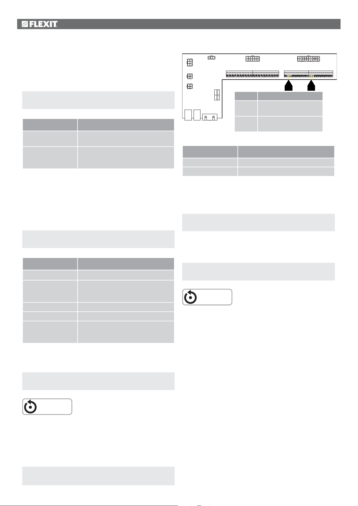
9.5. Settings for switching between summer
34 3 23
and winter operation
Switches between extract air regulation in the summer and
supply air regulation in the winter.
Start page > Main menu > Configuration >
Configuration 1 > Temp. regulation type
Parameter Function
Extract air SuWi Extract air regulation in summer and
supply air regulation in winter
Room SuWi Room regulation in summer and supply
air regulation in winter. NB! Requires
room sensors
9.6. Switch between summer and winter
via signal
The function can be changed via three factors: physical input,
date or outdoor temperature.
12 7
4
2
5
P6
3
6
123
P5
4
123
P4
4
P7
P14
P1P3 P2
1 2 3 4 5
1312
1 2 3 4 5 6 7 8 9
Block no.
P12-23 D1 Used if you have fire
829310411
16
5 623144155978
P8
10 11 12 13 14 15 16 17 18 19 20
Function
damper return
20 11
12131819 1617
110
P9
P12P10
21 22 23 24 25 26 27 28 29 30 31 32 33 34 35 36 37 38 39 40 41 42 43 44
3423
P12-34 D4 Used if you have
external speed control
Parameter Function
D1 Used if you have fire damper return
D4 Used if you have external speed control
If D1 is selected, the external speed control function must be
deactivated.
Physical input:
Start page > Main menu > Configuration >
Configuration 1 > SuWi input
Parameter Function
No Function deactivated
Yes Switches between summer and winter
operation.
1 = Summer & 0 = Winter
No heating Yes + Heating deactivated in the summer
No cooling. Yes + Cooling deactivated in the winter
Both Yes + Heating deactivated in the
summer & Cooling deactivated in the
winter
After making a change in a configuration menu, a restart is
required.
Start page > Main menu > Configuration >
Configuration 1 > Restart > Execute
Start page > Main menu > Configuration >
Configuration 1 > External control input > No
After making a change in a configuration menu, a restart is
required.
Start page > Main menu > Configuration >
Configuration 1 > Restart > Execute
RESTART
RESTART
A physical input must then be connected to the function.
There are various inputs to choose between, fire damper
return (fire damper is installed) and external speed control.
If the fire damper return is activated, the input for speed
control is used, and vice versa.
Start page > Main menu > Configuration >
Config. Inputs/Outputs > Digital inputs > SuWi input
40
Page 41
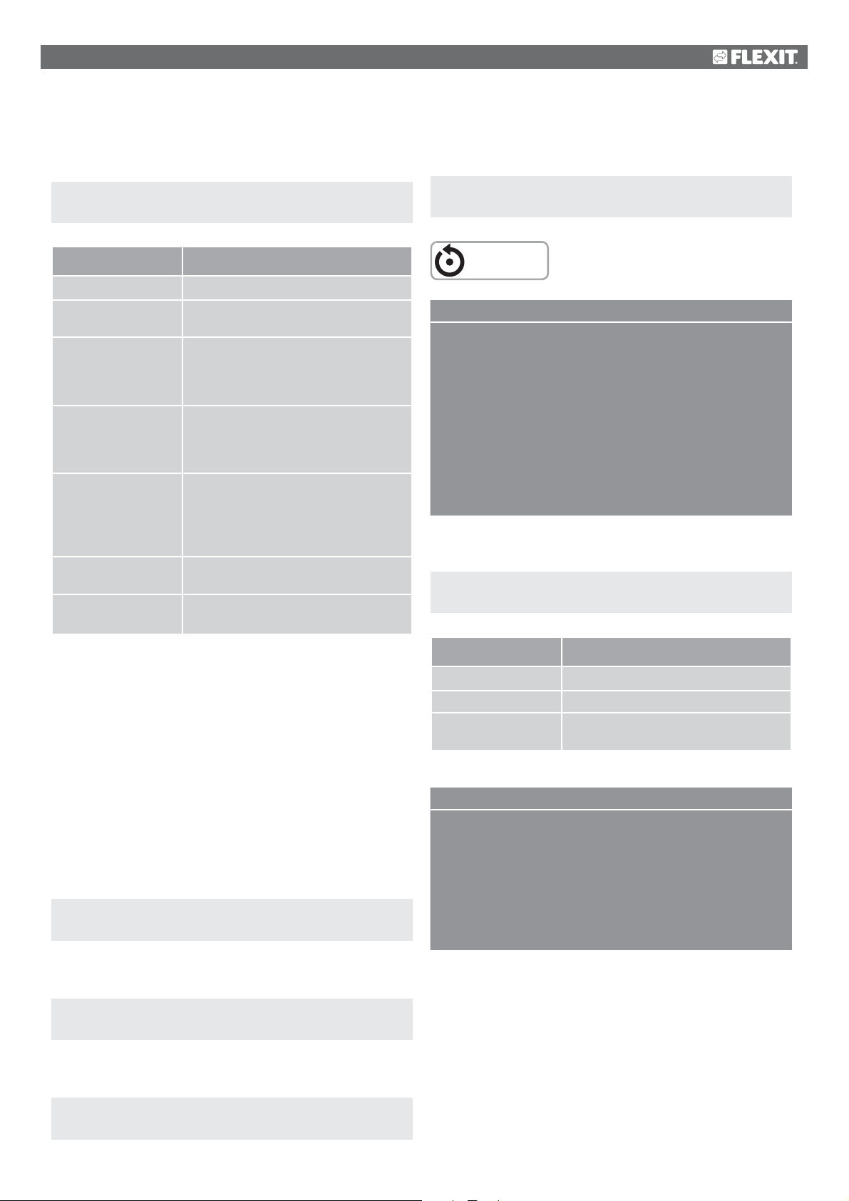
9.7. Switch between summer and winter via
date/outdoor temperature
Start page > Main menu > General functions >
Summer/winter mode
After making a change in a configuration menu, a restart is
required.
Start page > Main menu > Configuration >
Configuration 2 > Restart > Execute
Parameter Function
Status Display of current operating mode
Outdoor temperature
reduced
Date/Time, summer Date/time for switching to summer
Date/Time, winter Date/time for switching to winter
Time constant Time constant for calculation of Outdoor
Outdoor temp.
Summer
Outdoor temp. Winter Outdoor temperature for switching
Average outdoor air temperature over
given time constant
operation. If * is indicated instead of
date/time, switching is on Outdoor
temperature reduced
operation. If * is indicated instead of
date/time, switching is on Outdoor
temperature reduced
temperature reduced. Set to 0 for ten
seconds for reset of reduced outdoor
temperature. Set constantly to 0 for
switching on current outdoor temperature
Outdoor temperature for switching
to summer operation
to winter operation
RESTART
> EXAMPLE OF NIGHTTIME COOLING
Room setpoint = 22
Hysteresis = 2
Delta = 5
Min. outdoor air temp. = 10
Min. operating time = 30
When a temperature test is carried out, the room/extract air
is >24 degrees and the outdoor temperature is between 10
and 17 degrees.
The system starts and stops only when the room/extract air is
22 degrees and at least 30 minutes have passed since the start.
Configure as follows.
Start page > Main menu > Unit > Operating functions >
Nighttime operation temp. test
Parameter Function
Motion time Time of temperature test
9.8. Temperature test for nighttime operation
A temperature test starts the system after an extended
period of inactivity to update the duct sensor’s temperature.
This temperature is used as the criterion for starting
nighttime cooling or support operation and must always be
kept up to date.
The function is activated automatically when the following
conditions are met:
There is no room sensor:
Start page > Main menu > Configuration >
Configuration 1 > Room sensor temp. = No
Nighttime cooling or support operation is activated:
Start page > Main menu > Configuration >
Configuration 2 > Nighttime cooling > Yes
Or:
Start page > Main menu > Configuration >
Configuration 2 > Support operation > No
Interval time How often the temperature test is required
Pulse time Operating time for temperature test.
NB! not shorter than 180 seconds
> EXAMPLE OF TEMPERATURE TEST
Motion time = 23:00
Interval time = 3
Pulse time = 300
The system is switched on for 300 seconds if it has been
switched off for at least three hours from 23:00
NB! Motion time = *:* and interval time = 0.0 =
No temperature test is carried out.
41
Page 42
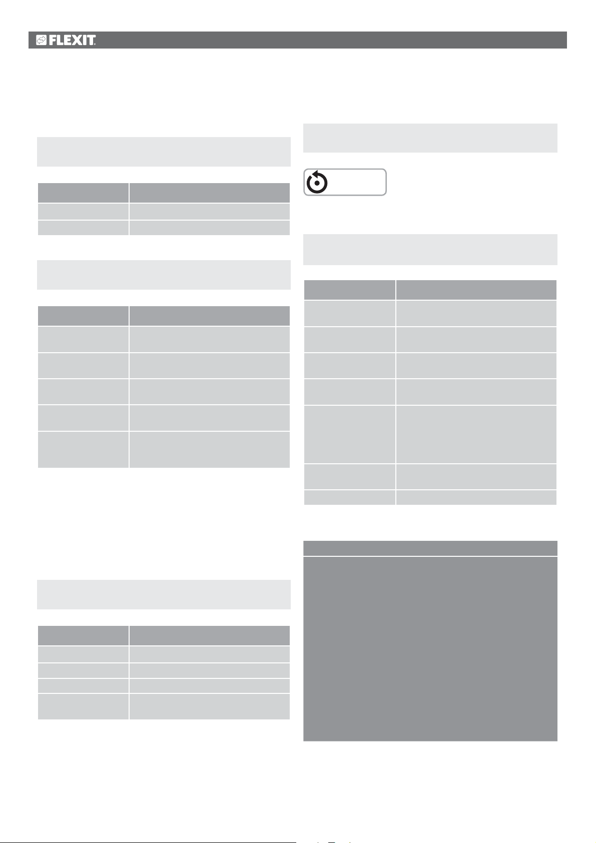
9.9. Nighttime cooling
Configure as follows:
Start page > Main menu > Configuration >
Configuration 2 > Nighttime cooling
Parameter Function
Yes Function activated
No Function deactivated
Start page > Main menu > Unit > Operating functions >
Nighttime cooling
Parameter Function
Room setpoint Displays the current setpoint for room/
extract air
Hysteresis Hysteresis for power up (Power up =
Room setpoint + Hysteresis).
Delta Minimum difference between room/
extract air and outdoor temperature
Min. outdoor temp. Lowest permitted outdoor temperature
to activate nighttime cooling
Min. operating time Shortest operating time in minutes after
start of nighttime cooling has been
activated
9.10. Support operation
Nighttime support operation prevents the building from
being heated or cooled too much. This is regulated via
a separate setpoint for heating and cooling.
9.10.1.
Parameter Function
No Function deactivated
Heating Function activated for heating
Cooling Function activated for cooling
HeatingCooling The function is activated for both
To activate the function
Start page > Main menu > Configuration >
Configuration 2 > Support operation
heating and cooling
After making a change in a configuration menu, a restart is
required.
Start page > Main menu > Configuration >
Configuration 2 > Restart > Execute
RESTART
9.10.2.
To configure the function
Start page > Main menu > Operating functions >
Support operation
Parameter Function
Start cooling Start temperature for cooling, extract air >
Start cooling
Setpoint for cooling Supply air setpoint for activated support
operation cooling
Start heating Start temperature for heating, extract
air > Start heating
Setpoint for cooling Supply air setpoint for activated support
operation cooling
Hysteresis Hysteresis for power down:
For cooling: Extract air < Start cooling Hysteresis
For heating: Extract air < Start heating +
Hysteresis
Min. restart time Shortest power down time after heating
or cooling has been activated
Min. operating time Shortest operating time after start
> EXAMPLE OF SUPPORT OPERATION COOLING
Start cooling = 25 degrees
Setpoint for cooling = 16 degrees
Hysteresis = 3 degrees
Min. restart time = 30 min.
Min. operating time = 15 min.
When a temperature test is carried out, the extract air is
26 degrees. The unit then switches to support operation
cooling and regulates the supply air to 16 degrees.
The system stops when the extract air has fallen to
22 degrees (Start cooling – Hysteresis), but no earlier
than after 15 minutes. Support operation starts again at
the earliest after 30 minutes after the last stop.
42
Page 43
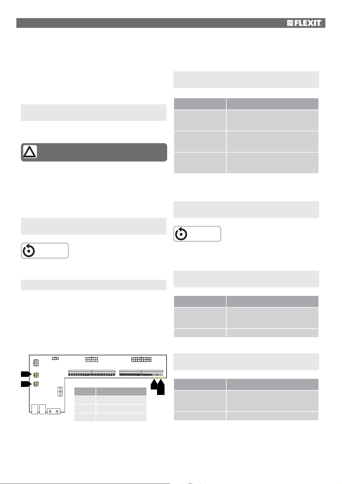
10. Fan regulation
Now use the control panel to configure the unit for pressure
control.
10.1. Select method of regulation
10.1.1.
All fan regulation functions are selected under the menu option:
'Flow regulation' is selected by default.
10.1.1.1. Fixed frequency
Frequency-controlled fans controlled with fixed steps via
analogue outputs [%].
After making a change in a configuration menu, a restart is
required.
Selection fan regulation method
Start page > Main menu > Configuration >
Configuration 1 > Fan regulation type
NB! The options 'Direct' and 'Dir. fro' must not
be used!
Start page > Main menu > Configuration >
Configuration 1 > Restart > Execute
Start page > Main menu > Configuration >
Configuration 1 > Fan regulation type
Parameter Function
Pressure reg. Requires 2 pressure sensors. The fans
are adjusted individually to their
respective setpoints
Supply air fan slave
Requires 1 pressure sensor for the extract
air fan. The supply air fan follows the extract
air fan with an adjustable slave offset
Extract air fan slave
Requires 1 pressure sensor for the supply
air fan. The extract air fan follows the supply
air fan with an adjustable slave offset
After making a change in a configuration menu, a restart is
required.
Start page > Main menu > Configuration >
Configuration 1 > Restart > Execute
RESTART
RESTART
Set parameters in the menu option:
Start page > Main menu > Unit > Setpoints/Settings
10.2. Pressure control
Before pressure control is selected, one or two pressure
sensors must be installed and connected to the unit.
If pressure sensors from Flexit are used, they must be
connected to P5 and P4. See the manual for the accessory.
If other makes are used, they must be connected to block
P12. See table.
20 11
12131819 1617
110
P9
P12P10
21 22 23 24 25 26 27 28 29 30 31 32 33 34 35 36 37 38 39 40 41 42 43 44
40
43 4440
43
44
P5
P4
12 7
4
2
5
3
6
123
4
123
4
1312
P6
P7
P5
P4
1 2 3 4 5
1 2 3 4 5 6 7 8 9
P14
P1P3 P2
Block no.
40 Earth signal G0
43 Supply air fan 0-10 V
829310411
16
5 623144155978
P8
10 11 12 13 14 15 16 17 18 19 20
Function
44 Extract air fan 0-10 V
10.2.1.
Configuration of the pressure sensors’
measuring ranges
Start page > Main menu > Configuration > Config.
Inputs/Outputs > Pressure/Flows > Supply air pressure
Parameter Function
X6 500 Pa X6 = Physical input (must not be
changed). 500 Pa = Max. set value of
connected pressure sensor.
Type 0-10 V Type of signal. Must not be changed.
Start page > Main menu > Configuration > Config.
Inputs/Outputs > Pressure/Flows > Extract air pressure
Parameter Function
X7 500 Pa X7 = Physical input (must not be
changed). 500 Pa = Max. set value of
connected pressure sensor.
Type 0-10 V Type of signal. Must not be changed.
43
Page 44
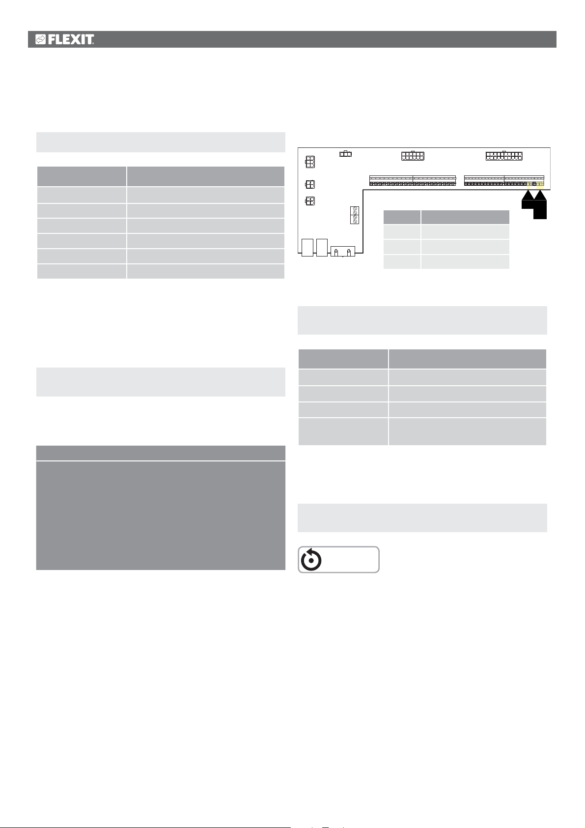
10.2.2.
43
4
Pressure setpoint adjustment.
If SF or EF is selected to operate as a slave, only three
setpoint steps are displayed.
Start page > Quick menu > Setpoints/Settings
Parameter Function
Setp.TF step 1 Supply air fan setpoint speed 1
Setp.TF step 2 Supply air fan setpoint speed 2
Setp.TF step 3 Supply air fan setpoint speed 3
Setp.FF step 1 Extract air fan setpoint speed 1
Setp.FF step 2 Extract air fan setpoint speed 2
Setp.FF step 3 Extract air fan setpoint speed 3
If SF slave or EF slave is selected for the fan regulation type,
an offset must be set against which the fan selected is regulated.
The supply air/extract air fan is pressure-regulated. The
supply air/extract air flow is calculated and regulated against
the slave offset. See example.
Start page > Main menu > Unit >
Fan control > Slave offset
Explanation: The offset indicates the difference between the
master fan and the slave fan.
> EXAMPLE OF OFFSET
Example 1: If the offset is 0 l/s, the slave fan
operates with the same flow as the
master fan.
Example 2: If the offset is -100 l/s, the slave fan
operates with 100 l/s lower flow than
the master fan.
Example 3: If the offset is 100 l/s, the slave fan
operates with 100 l/s higher flow than
the master fan.
10.3. External fan setpoint
The fans can be controlled directly via an analogue 0-10 V
input on the automatic control. Min. and max. speeds/flows
are defined, which correspond to 0 V and 10 V on the input.
12 7
4
2
5
P6
3
6
123
P5
4
123
P4
4
P7
P14
P1P3 P2
1 2 3 4 5
1312
1 2 3 4 5 6 7 8 9
Block no.
40 Earth signal G0
43 Supply air fan 0-10 V
829310411
16
5 623144155978
P8
10 11 12 13 14 15 16 17 18 19 20
Function
44 Extract air fan 0-10 V
Activated via the following menu option:
Start page > Main menu > Configuration >
Configuration 2 > Ext. Setpoint, fan
Parameter Function
No Not activated
SF External control of supply air fan
EF External control of extract air fan
SF + EF External control of both supply air
and extract air fans
After making a change in a configuration menu, a restart is
required.
Start page > Main menu > Configuration >
Configuration 2 > Restart > Execute
RESTART
20 11
12131819 1617
110
P9
P12P10
21 22 23 24 25 26 27 28 29 30 31 32 33 34 35 36 37 38 39 40 41 42 43 44
40
4440
43
44
44
Page 45
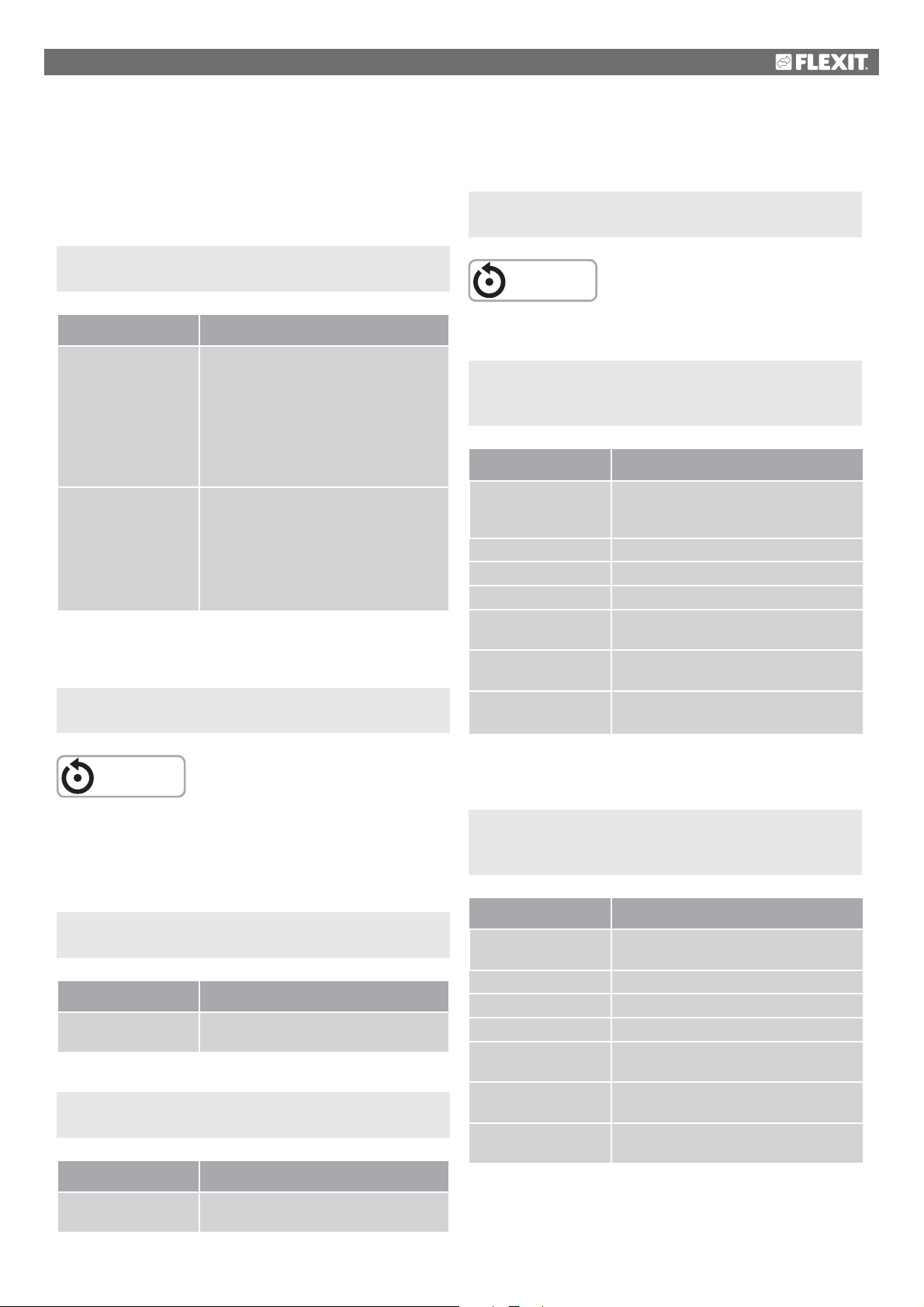
The function has two operating modes:
1. Comp. A basic flow via step 1, 2 or 3 on which
the fan operates + comp.
2. Main. The fan is controlled only via the 0-10 V input
and steps 1, 2 and 3 are inactive.
Start page > Main menu > Configuration >
Configuration 2 > Ext. setpoint function SF/EF
After making a change in a configuration menu, a restart is
required.
Start page > Main menu > Configuration >
Config. Inputs > Restart > Execute
RESTART
Parameter Function
Comp. Example of Comp.
Comp. is set to 0 V = 0 l/s and 10 V = 500 l/s
Step 1 is set to 100 l/s and the input
for the external setpoint is 0 V. The fan
operates at 100 l/s
Step 2 is set to 300 l/s and the input
for the external setpoint is 10 V. The fan
operates at 800 l/s
Main Example of Main.
Main is set to 0 V = 100 l/s and 10 V =
1,000 l/s
The input for the external setpoint is 0 V.
The fan operates at 100 l/s
The input for the external setpoint is 5 V.
The fan operates at 500 l/s
After making a change in a configuration menu, a restart is
required.
Start page > Main menu > Configuration >
Configuration 2 > Restart > Execute
RESTART
10.3.1.
Parameter settings for Comp.
Start page > Quick menu > Setpoints/Settings >
All settings > Fan control >
Supply air fan/Extract air fan
Parameter Function
Current setpoint
supply air/extract air
Step 1 Supply air/extract air fan setpoint speed 1
Step 2 Supply air/extract air fan setpoint speed 2
Step 3 Supply air/extract air fan setpoint speed 3
Ext. setpoint curve Y1 Scaling of the 0-10 V signal,
Ext. setpoint curve Y2 Scaling of the 0-10 V signal,
External setpoint
SF/EF
Displays the current setpoint for the
supply air/extract air fan, including
compensation.
speed/flow at 0 V
speed/flow at 10 V
Displays the current setpoint for the
0-10 V input
10.3.2.
Parameter settings for Main
After the restart, the unit starts with an alarm:
‘External SF/EF setpoint config. error’. This means that one
or two physical inputs must be defined for the function.
This is done via:
Start page > Main menu > Configuration >
Config. Inputs/Outputs > Other > Ext. Setpoint, SF
Parameter Function
X6 Defines the input to which the function
must be connected
Start page > Main menu > Configuration >
Config. Inputs/Outputs > Other > Ext. Setpoint, EF
Parameter Function
X7 Defines the input to which the function
must be connected
Start page > Quick menu > Setpoints/Settings >
All settings > Fan control >
Supply air fan/Extract air fan
Parameter Function
Current setpoint
supply air/extract air
Step 1 Not active
Step 2 Not active
Step 3 Not active
Ext. setpoint curve Y1 Scaling of the 0-10 V signal, speed/flow
Ext. setpoint curve Y2 Scaling of the 0-10 V signal, speed/flow
External setpoint
SF/EF
Displays the current setpoint for the
supply air/extract air fan
at 0 V
at 10 V
Displays the current setpoint for the
0-10 V input
45
Page 46
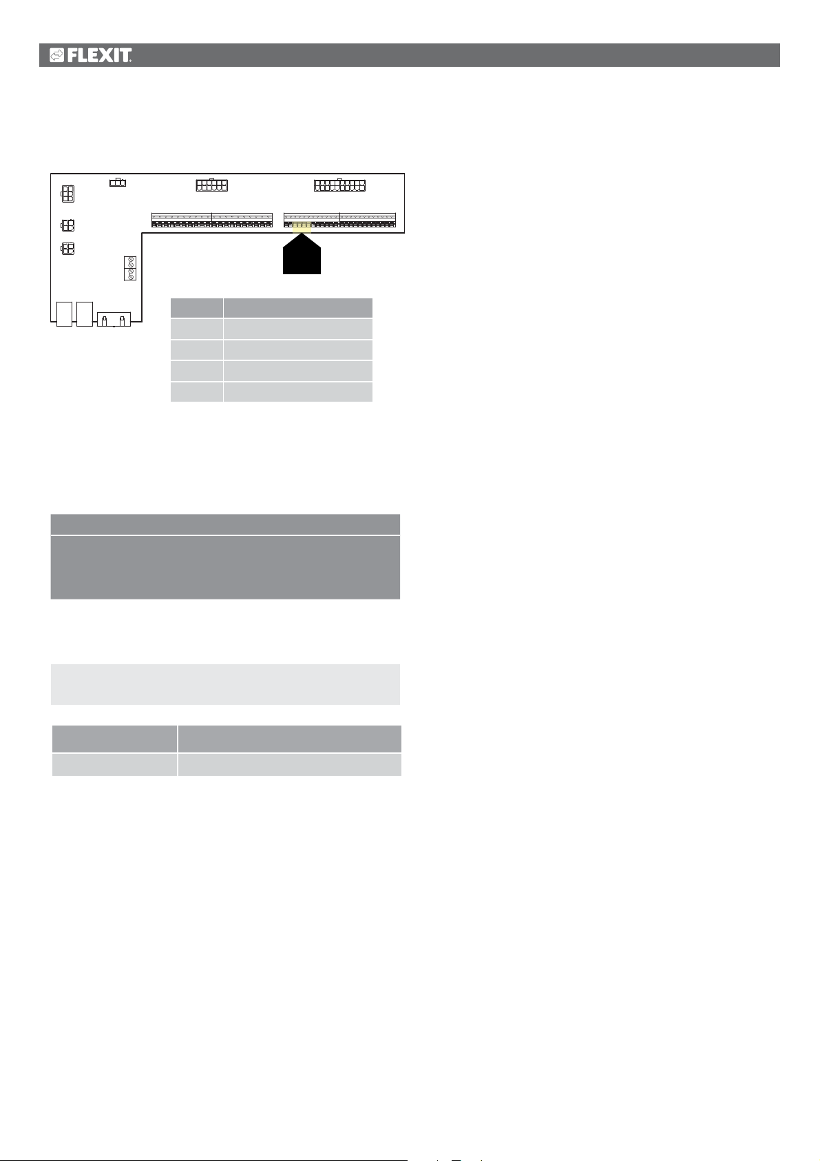
10.4. External fan control via digital inputs
12 7
4
2
5
P6
3
6
123
P5
4
123
P4
4
P7
P14
P1P3 P2
1 2 3 4 5
1312
1 2 3 4 5 6 7 8 9
Block no.
829310411
16
5 623144155978
P8
10 11 12 13 14 15 16 17 18 19 20
Function
20 11
12131819 1617
110
P9
P12P10
21 22 23 24 25 26 27 28 29 30 31 32 33 34 35 36 37 38 39 40 41 42 43 44
23 24 25 26
23, 24
25, 26
23 External control 1 (DI)
24 External control 1 (G0)
25 External control 2 (DI)
26 External control 2 (G0)
Connection of signal(s) for controlling fan speeds from
external components. It is possible to connect various
types of switch/sensor that have pulse or fixed positions.
By default the regulator is set for switches with fixed values.
> EXAMPLE OF EXTERNAL CONTROL
Control 1 ON = Speed 1
Control 2 ON = Speed 2
Controls 1 & 2 ON = Speed 3
Speed 3 can be configured to Stop. This is done via:
Start page > Main menu > Unit > Operating functions >
External control > Fan step
Parameter Function
Off External inputs 1 and 2 ON produce stop
10.5. Fire fan
The unit has a potential-free output to control an external
fire fan. This requires the expansion module SP90 to be
installed.
46
Page 47
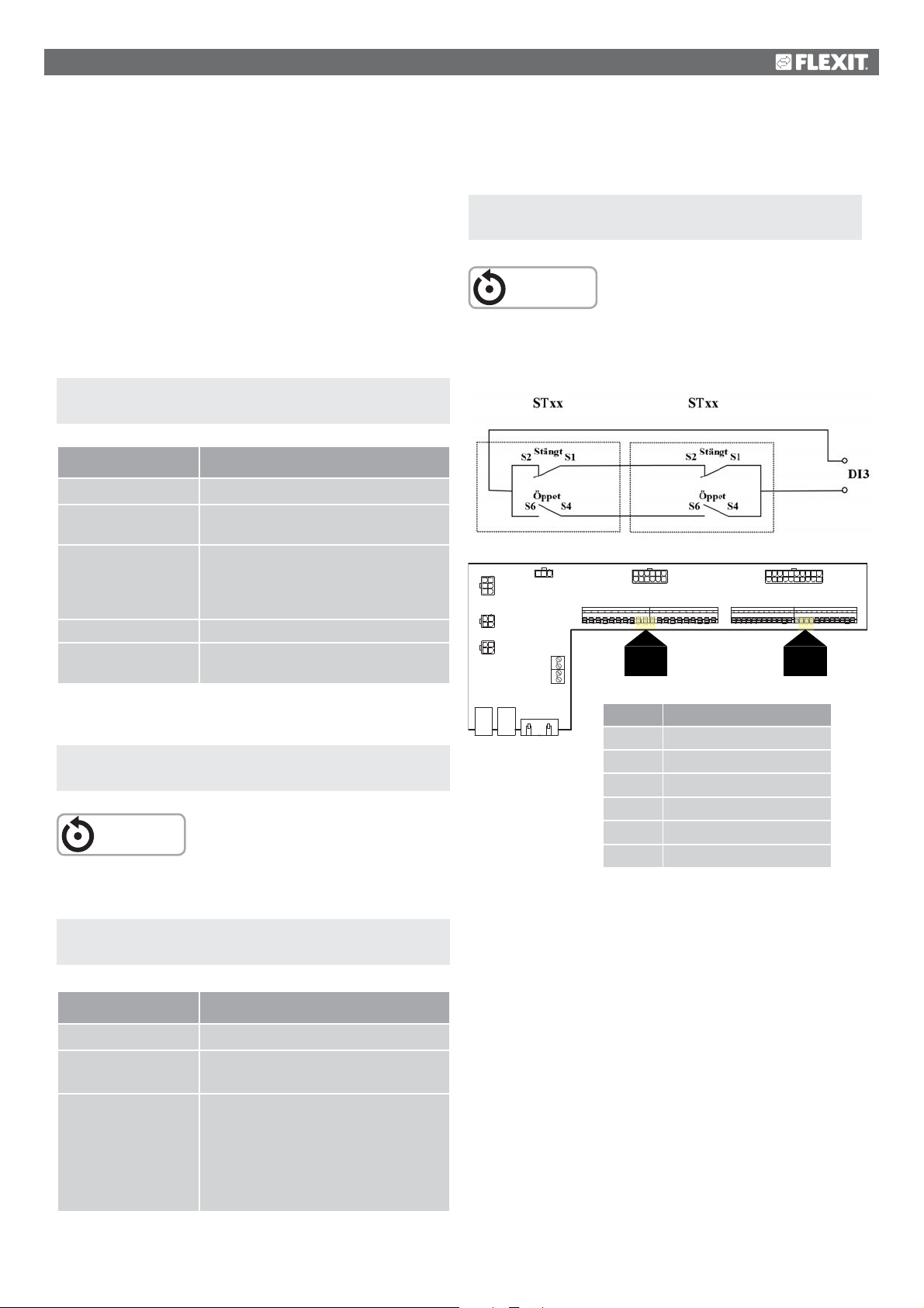
11. Connection of external
equipment
After making a change in a configuration menu, a restart is
required.
11.1. Fire damper
The unit can control fire dampers and operate them for
maintenance. Fire dampers can be included in the system
control, either via autotest or always open. Defined limit
positions are monitored. The current status and operating
mode of the dampers are displayed.
To activate the function.
Start page > Main menu > Configuration >
Configuration 1 > Fire damper
Parameter Function
No Function deactivated
Yes Function activated. One digital output
and input each for fire damper regulation
Yes + FollUnit Function activated. One digital output
and input each for fire damper regulation.
The fire damper is opened when the unit
starts and closed when the unit stops.
2-4 Same as ‘Yes’ but with 2-4 fire dampers
2-4 + FollUnit Same as ‘Yes+FollUnit’ but with 2-4 fire
dampers
After making a change, a restart is required.
Start page > Main menu > Configuration >
Configuration 1 > Restart > Execute
RESTART
Start page > Main menu > Configuration >
Configuration 2 > Restart > Execute
RESTART
Connection description for fire damper indication with
combined signal for open and closed.
12 7
4
2
5
P6
3
6
123
P5
4
123
P4
4
P7
P14
P1P3 P2
1 2 3 4 5
1312
1 2 3 4 5 6 7 8 9
Block no.
829310411
16
5 623144155978
P8
10 11 12 13 14 15 16 17 18 19 20
9
10 11
9, 10
11
Function
P10-9 L (Fire damper)
P10-10 L1 (Fire damper ON/OFF)
P10-11 N (Fire damper)
P12-34 Fire damper open [DI]
P12-35 Fire damper closed [DI]
P12-36 Fire damper - G0
20 11
P9
P12P10
21 22 23 24 25 26 27 28 29 30 31 32 33 34 35 36 37 38 39 40 41 42 43 44
34 35 36
34, 35
36
12131819 1617
110
Continue to configure the return of the fire damper.
Start page > Main menu > Configuration >
Configuration 2 > Fire damper return
Parameter Function
Closed Only one return for closed damper.
Clo + Op Two separate returns for open and
closed positions.
Combi Returns for open and closed modes,
but only one signal/input with
sequence as below:
1 (closed) ---> 0 (closes/opens)
---> 1 (open)
The fire dampers must be connected according to the above
diagram to ensure correct operation.
47
Page 48
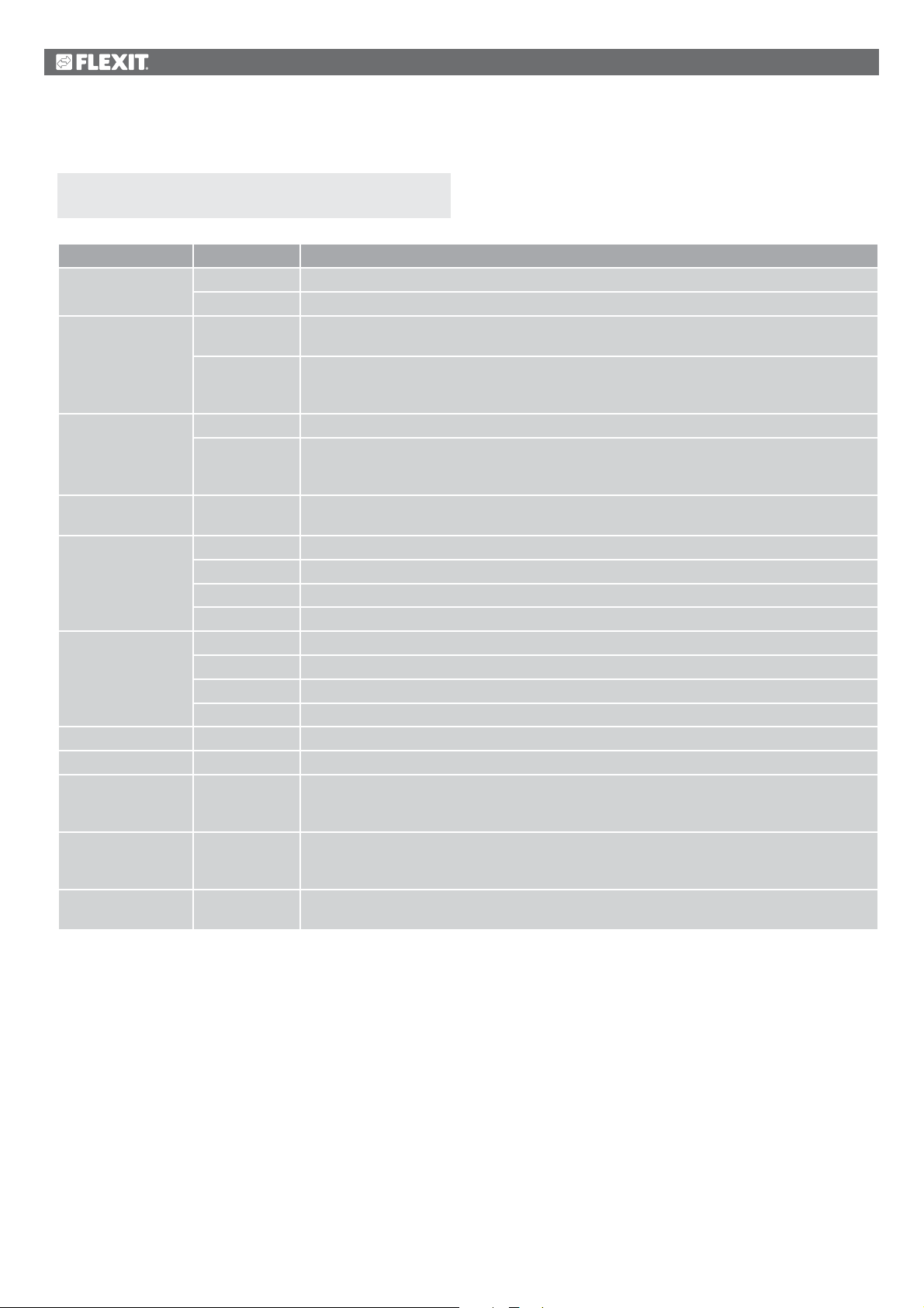
Configure as follows.
Start page > Main menu > Unit > Damper control >
Fire damper
Parameter Value Function
Operation Off Current status of outdoor air damper.
On Go to the page for all settings for digital outputs.
Return open mode OK Active return if the damper is open. The parameter is activated automatically after 115% of the
time in open mode if return for open mode is not activated in Configuration 2.
1 / 2 / 3 / 4
+ all possible
combinations
Return closed mode OK Active return if the damper is closed. This must always be set.
1 / 2 / 3 / 4
+ all possible
combinations
No movement OK
Alarm
Status N/A Possible only in connection with configuration.
Closed Closed.
Cl/Op Closes/opens.
Open Open. See example below.
Operating mode N/A Possible only in connection with configuration.
OK OK.
Test Test mode.
Alarm Alarm mode.
Open time 1…600 [s] Time for damper opening (see product sheet for damper actuator).
Close time 1…600 [s] Time for damper closing (see product sheet for damper actuator).
Start manual test Passive
Active
Motion Time, Weekday,
Date
Test interval 0...36000 [h] Time interval for automatic damper test.
The figures indicate which damper has an error.
The figures indicate which damper has an error.
No reaction to the alarm message for both returns if the damper operation has been changed.
See example below.
The time for automatic start of the damper test. Autotest is deactivated for Configuration 1 >
Fire damper = Yes+FollUnit.
See example below.
The time for automatic start of the damper test.
Autotest is deactivated for Configuration 1 > Fire damper = Yes+FollUnit.
See example below.
See example below.
48
Page 49

> EXAMPLE OF DAMPER OPERATION 0 -> 1:
After 15% of the time in open mode, return must be Closed Otherwise an alarm is triggered for no movement.
After 115% of the time in open mode, return must be Open Otherwise a return alarm is triggered for open mode
Damper operation 1 -> 0.
> EXAMPLE OF DAMPER OPERATION 1 -> 0:
After 15% of the time in closed mode, return must be Open Otherwise an alarm is triggered for no movement.
After 115% of the time in closed mode, return must be Closed Otherwise a return alarm is triggered for closed mode.
An automatic test can be carried out at a certain time (day, time) and/or at a certain interval.
> EXAMPLE OF TEST INTERVAL:
Motion = *:* *,*.* / Test interval = 24 A test is carried out every 24 hours, regardless of the time
Motion = 23:* Mo,*.* / Test interval = 47 h A test is carried out every month at 23:00, with the previous test
having been carried out at least 47 hours earlier.
Motion = *:* *,*:* and Autotest interval = 0 No automatic test is carried out.
Test sequence = 1
Test mode; the entire unit stops. After the Power down delay period, the outdoor air and extract air dampers are closed and a
fire damper test is initiated.
> EXAMPLE OF SWITCH TO 1 -> 0:
After 15% of the time in closed mode, return must be Open Otherwise an alarm is triggered for no movement.
After 115% of the time in closed mode, return must be Closed Otherwise a return alarm is triggered for closed mode.
If everything works as intended:
> EXAMPLE OF SWITCH TO 0 -> 1:
After 15% of the time in open mode, return must be closed Otherwise an alarm is triggered for no movement.
After 115% of the time in open mode, return must be Open Otherwise a return alarm is triggered for open mode.
The unit confirms OK and starts.
49
Page 50
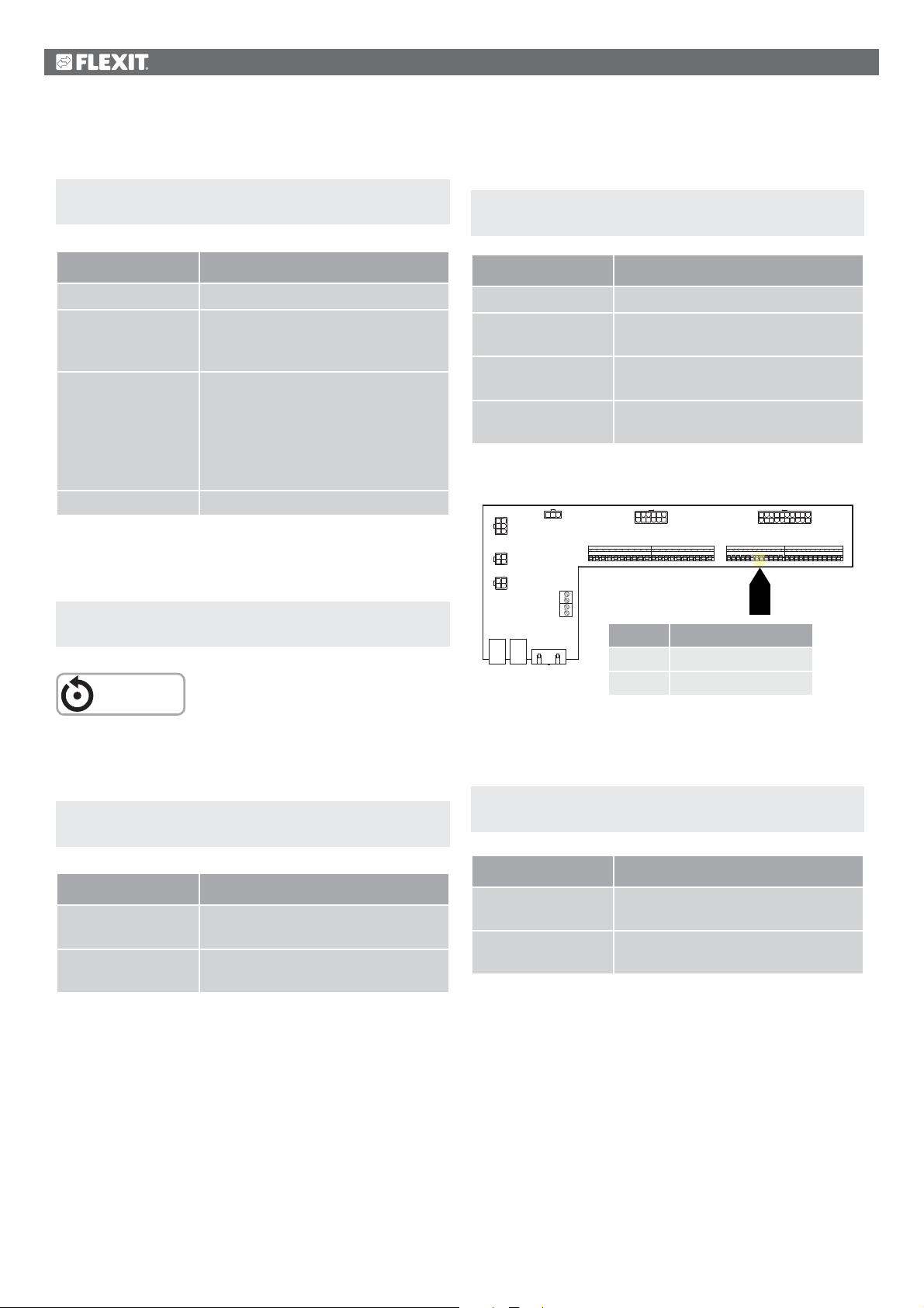
2
11.2. Fire/smoke detector
For selection of Alarm or Alarm+Temp, the fan regulation is
configured as follows:
Start page > Main menu > Configuration >
Configuration 1 > Fire alarm
Parameter Function
No No fire alarm.
Alarm External fire alarm such as smoke
detectors, thermostat, fire alarm
control centre, etc.
Temp Internal fire alarm via measurement
of normal supply air and extract air
temperature when both sensors are
accessible. A fire alarm is triggered
when one of the two temperatures
reaches a specific value.
Alarm+Temp Both fire alarms.
After making a change in a configuration menu, a restart is
required.
Start page > Main menu > Configuration >
Configuration 1 > Restart > Execute
RESTART
Start page > Main menu > Unit > Fan control > Fire
function
Parameter Function
Stop The fans stop in the event of fire.
SF operation The supply air fan operates on the set
max. step. The extract air fan stops.
EF operation The extract air fan operates on the set
max. step. The supply air fan stops.
Operation Both fans operate on the set
max. step.
12 7
4
2
5
3
6
123
4
123
4
1312
P6
P7
P5
P4
1 2 3 4 5
1 2 3 4 5 6 7 8 9
P14
P1P3 P2
829310411
16
5 623144155978
P8
10 11 12 13 14 15 16 17 18 19 20
Block no.
Function
27 Fire/smoke [DI]
28 Fire/smoke [G0]
20 11
12131819 1617
110
P9
P12P10
21 22 23 24 25 26 27 28 29 30 31 32 33 34 35 36 37 38 39 40 41 42 43 44
27 28
27
28
For selection of Temp or Alarm+Temp, the alarm limits for the
temperatures are configured as follows:
Start page > Quick menu > Setpoints/Settings >
All settings > Alarm limits
Parameter Function
Supply air temp. fire
limit
Extract air temp.
fire limit
Alarm limit for high supply air
temperature.
Alarm limit for high extract air
temperature.
The input is normally open (NO) and produces an alarm if it
closes. This can be reconfigured to normally closed (NC) via:
Start page > Main menu > Unit > Inputs > Fire >
Contact function
Parameter Function
NO Normally open = produces an alarm
if the input closes.
NC Normally closed = produces an
alarm if the input opens.
50
Page 51
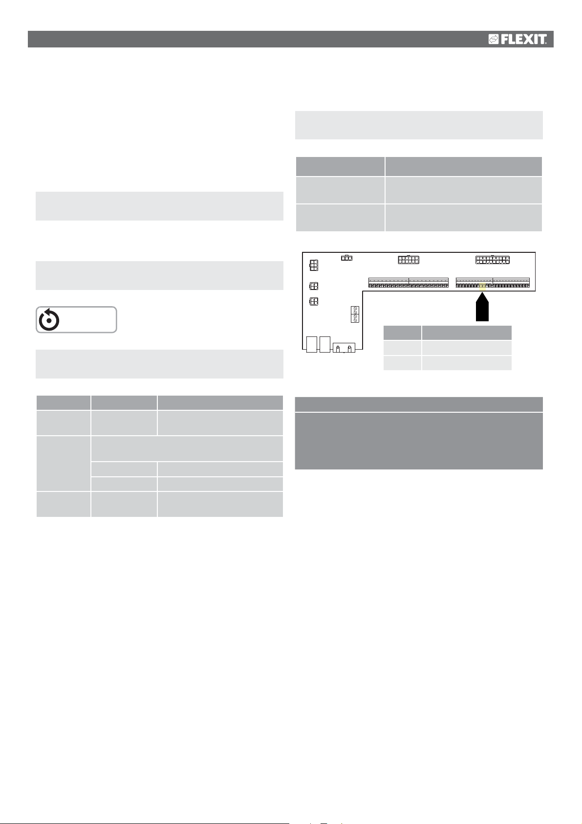
29 30
11.3. Air quality
Fans (see Fan compensation) are regulated based on air
quality. The outdoor air volume increases when the carbon
dioxide content exceeds a certain value (the fan speed
increases and the circulation volume decreases). The
outdoor air volume decreases when the carbon monoxide
content exceeds a set value (the fan speed decreases and
the circulation volume increases).
Start page > Main menu > Configuration >
Configuration 2 > Fan comp. air quality = Yes
After making a change in a configuration menu, a restart is
required.
Start page > Main menu > Configuration >
Configuration 1 > Restart > Execute
RESTART
Start page > Main menu > Unit >
Air quality regulation
Scaling of the CO2 sensor
Start page > Main menu > Configuration >
Config. Inputs/Outputs >
Parameter Function
Other > Air quality sensor
X8 This is the physical input for the
regulator and must not be changed.
2000 ppm This is the upper limit for the CO2
sensor. With 10 V in the output
12 7
4
2
5
3
6
123
4
123
4
1312
P6
P7
P5
P4
1 2 3 4 5
1 2 3 4 5 6 7 8 9
P14
P1P3 P2
829310411
16
5 623144155978
P8
10 11 12 13 14 15 16 17 18 19 20
Block no.
Function
29 (0-10 V)
30 (G0)
20 11
12131819 1617
110
P9
P12P10
21 22 23 24 25 26 27 28 29 30 31 32 33 34 35 36 37 38 39 40 41 42 43 44
29
30
Parameter Value Function
Regulator 0…100 [%] Current regulator value. Go to
the page for regulator settings
Function The output signal must be selected based on
current requirements:
Normal Normal for CO2
Inverted Inverted for carbon monoxide.
Setpoint 0…3000 [ppm] Setpoint for air quality
regulation.
> EXAMPLE OF CO2 REGULATION
The setpoint is set to 800 ppm and the CO2 sensor detects
an actual value of 1,000 ppm. The unit switches up to speed
3 and remains at this speed until the CO2 sensor detects an
actual value below 800 ppm, at which time the unit switches
down to the speed set in the current time channel.
51
Page 52
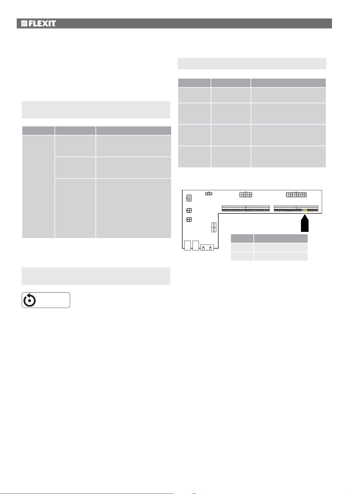
11.4. AUX Damper
The output signal is affected by the speed of the ventilation
unit. The function can be used, for example, to open
a damper when the unit switches to a higher speed.
The function must be activated in the control system.
This is done via the following menu option.
Start page > Main menu > Configuration >
Configuration 2
Parameter Value Function
Aux. output
signal
After making a change in a configuration menu, a restart is
required.
No Analogue aux. output that
generates a 0-10 V signal,
depending on current fan step.
Fan An output signal can be set for
each fan step. For example 10%
at step 1 and 60% at step 2.
Flow device The output signal here depends
on the difference between the
supply air temperature and the
room temperature. Adjustable
to the difference that produces
0 V and 10 V. For example
supply air temperature-room
temperature = 5 degrees
produces a 7 V output signal.
Start page > Main menu > Unit > Auxiliary
Parameter Value Function
Fan step 0 0…100 [%] Aux. output signal when unit is
off (also for system error).
Fan step 1 0…100 [%] Aux. output signal with active
fan step 1 (setpoint 1 for
regulated fans).
Fan step 2 0…100 [%] Aux. output signal with active
fan step 2 (setpoint 2 for
regulated fans).
Fan step 3 0…100 [%] Aux. output signal with active
fan step 3 (setpoint 3 for
regulated fans).
12 7
4
2
5
3
6
123
4
123
4
1312
P6
P7
P5
P4
1 2 3 4 5
1 2 3 4 5 6 7 8 9
P14
P1P3 P2
829310411
16
5 623144155978
P8
10 11 12 13 14 15 16 17 18 19 20
Block no.
Function
37 (0-10 V)
38 (G0)
20 11
12131819 1617
110
P9
P12P10
21 22 23 24 25 26 27 28 29 30 31 32 33 34 35 36 37 38 39 40 41 42 43 44
37 38
37
38
Start page > Main menu > Configuration >
Configuration 2 > Restart
RESTART
52
Page 53
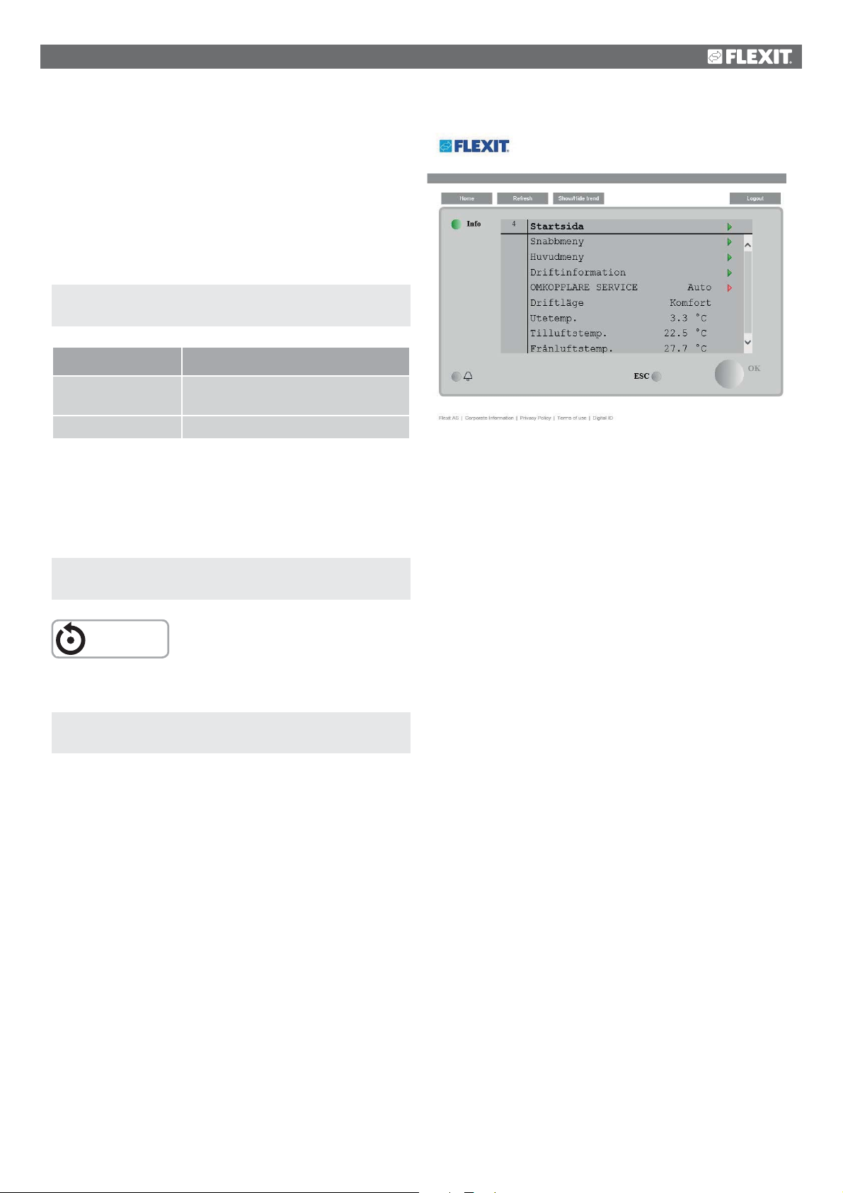
12. Web
The unit can be controlled via the web. This is done by the
control panel being mirrored in a web browser. If you want to
have flow charts showing the current values for temperatures,
flows, etc., a web module (accessory) must be installed.
To configure the function, go to the following menu:
Start page > Main menu > System overview >
Communication > TCP/IP > DHCP
Parameter Function
Active The regulator is assigned an
IP address from the network
Passive A fixed IP address is set in the regulator
Information on other settings under the communication
menu is available from the staff in charge of the network.
After making a change, a restart is required.
You can now navigate using the arrow keys and ESC to go in
and out of menus.
Start page > Main menu > System overview >
Communication > TCP/IP > Restart
RESTART
After restart, go to:
Start page > Main menu > System overview >
Communication > TCP/IP
and make a note of the Current IP.
Then go to Other settings further down the same menu.
Make a note of the User name and Password.
Then open your web browser, go to the IP address you noted
down and log in with the User name and Password you
noted down.
53
Page 54
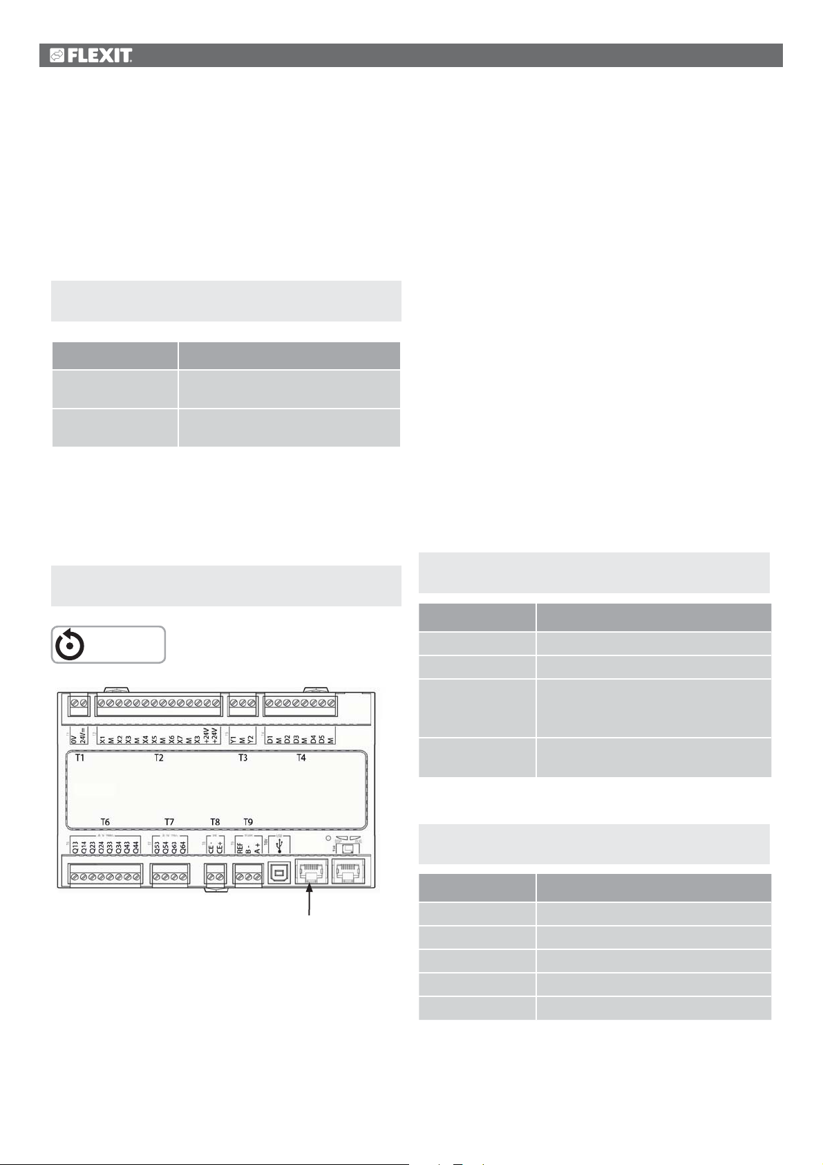
13. ModBus TCP/IP
14. DX heating/cooling
The unit can be controlled via ModBus TCP/IP as a default
function in the regulator. If you want to have ModBus with
RS485 serial communication, a communication module
(accessory) must be installed.
To configure the function, go to the following menu:
Start page > Main menu > System overview >
Communication > Modbus> TCP/IP > DHCP
Parameter Function
Active The regulator is assigned an
IP address from the network
Passive A fixed IP address is set in
the regulator
Information on other settings under the communication
menu is available from the staff in charge of the network.
After making a change, a restart is required.
Start page > Main menu > System overview >
Communication > Modbus > Restart
This function is only available on software V3.07 and later.
To see the current version for the unit:
Main menu > System overview > Versions > Flexit AHU
If the function is needed on older versions, contact Flexit.
The control system is able to control a heat pump for
heating and cooling, which is connected to ducted coils. It
can be used both as a free-standing unit or in sequence
ahead of the internal electric-powered coils, which can then
be used as peak heating and/or as reserve heating while the
heat pump is defrosting.
For the function to operate, I/O module SP90 must
be installed and configured. See Manual 112548.
If you wish to use the internal electric-powered
coils, these must be installed/configured as shown in
the manual supplied with the coils.
14.1. Configuration of control system
Start page > Main menu > Configuration >
Configuration 1 > Additional heating
RESTART
Connect here.
The parameter list for ModBus can be downloaded at
www.flexit.com.
Parameter Function
No Additional heating deactivated
Yes Additional heating activated
Yes+Preh+Outd. Additional heating with preheating
based on outdoor air temperature.
Analogue heating valve output.
Yes+Preh.Frost
protection temp.
Select Yes to activate the function.
Start page > Main menu > Configuration >
Configuration 1 > Additional cooling
Parameter Function
No Additional cooling deactivated
Water Additional cooling via 0-10V signal
DX 1step Additional cooling Off/On 1 step
DX 2step Additional cooling Off/On 2 step
DX 3step Additional cooling Off/On 3 step
Additional heating with preheating
based on frost protection temperature.
Select Water to activate the 0-10V output signal for the
function. After making a change in a configuration menu,
RESTART.
54
Page 55
RESTART
Start page > Main menu > Configuration >
Configuration 2 > Additional cooling regulation
The unit will show an alarm on startup. This can be removed
by the configuration shown further down.
Start page > Main menu > Configuration >
Configuration 2 > Pump, additional heating
Parameter Function
No No Off/On signal to pump
Yes Off/On signal to pump
Yes+Exercise No Off/On signal to pump +
exercise operation
Select Yes. Used to signal a heating/cooling requirement to
the heating pump. Closes a circuit in the event of a heating
requirement.
After restarting, toggle between open and closed contact
using the following menu:
Start page > Main menu > Unit > Outputs > Pump
Add. heat > Contact function = NO /NC
Start page > Main menu > Configuration >
Configuration 2 > Heat pump defrosting
Parameter Function
Standalone Regulation seeks its own temperature
target value
Sequence Regulation uses the sequence before
or after ordinary cooling regulation
Select Sequence to force the regulation to operate in
sequence with heat recovery and heating.
Start page > Main menu > Configuration >
Configuration 2 > E.g. Combi Coil
Parameter Function
No Function deactivated
1output Function activated shared output
2outputs Function activated two different
outputs
Select 1output to send the same signal (0-10V) to the heat
pump for both heating and cooling.
After making a change in a configuration menu, RESTART.
RESTART
Parameter Function
No Defrosting function deactivated
Yes Defrosting function activated
Select Yes. Used to lock the output signal to the heat pump
and if necessary activate electric heating (if connected)
when defrosting the heat pump.
Start page > Main menu > Configuration >
Configuration 2 > Additional heating regulation
Parameter Function
Standalone Regulation seeks its own
temperature target value
Sequence HeatingAdditional heating
Sequence Additional
heating-Heating
Regulation uses the sequence heat
pump - electrical heating
Regulation uses the sequence
electrical heating - heat pump
Select Sequence Additional heating - Heating to force
the regulation to operate using the sequence Heat pump
first and electrical heating second.
After restarting, an alarm will appear on the regulator
requiring configuration of which input is connected to the
heat pump defrosting function.
Start page > Main menu > Configuration >
Config. In/Outputs > Digital inputs > Heat pump
defrosting
Parameter Function
D4 Block P12-35
Select D4. This will connect block P12-35 on the A2 circuit
board to the function. The input is also used for resetting the
fire damper. If both functions are used, contact Support to
configure a new input.
55
Page 56
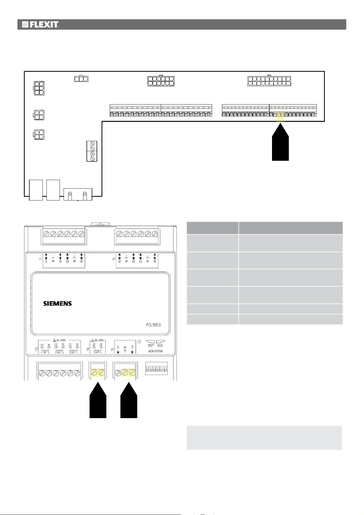
14.2. Installation
12 7
4
2
5
P6
3
6
1312
P7
829310411
16
5 623144155978
P8
20 11
12131819 1617
P9
110
P12P10
123
P5
4
123
P4
4
1 2 3 4 5 6 7 8 9
10 11 12 13 14 15 16 17 18 19 20
21 22 23 24 25 26 27 28 29 30 31 32 33 34 35 36 37 38 39 40 41 42 43 44
35 36
35
P14
P1P3 P2
1 2 3 4 5
Block no. Function
Q43 Heating/cooling operating signal to
Heat Pump IN
Q44 Heating/cooling operating signal to
Heat Pump OUT
M Signal heating/cooling to Heat Pump
(G0)
Y11 Signal heating/cooling to Heat Pump
(0 -10V)
35 Heat pump defrosting (DI)
36
Q43
Q44
Y2
M
36 Heat pump defrosting (G0)
The function works in such a way that when the heat pump is
defrosting (signal in on block P12-35), the control system is
automatically started up
from the regulator to the heat pump until defrosting plus an
extra period has elapsed, when it will start to regulate again.
If internal electrical coils have been installed and configured,
these will attempt to maintain the supply air temperature
during the defrosting period. This is to prevent the heating
sequence switching over when the heat pump has finished
defrosting.
To adjust the function’s locking time:
Start page > Main menu > Unit > Temperature
regulation > Additional heating > Heat pump
defrost. Lock electrics
The standard setting is 60 seconds.
56
Page 57

575859
Page 58

Page 59

Page 60

Flexit AS, Televeien 15, NO-1870 Ørje www.flexit.no
 Loading...