

Page 1

Item No. H2S
In s tal l ati o n Guid e
01
Warning
·The p ackag ing mat erial s of this p roduc t could b e dange rous to y oung ch ildre n. Plea se keep a ll
pla stic ba gs, scr ews, to ols and o ther sm all or po tenti ally ha zardo us mate rials a way fro m young
chi ldren a s they ma y prese nt a chok ing ris k.
·Thi s Flexi spot de sk shou ld not be u sed by ch ildre n. To avo id pote ntial d anger, k eep chi ldren a nd
peo ple wit h cogni tive im pairm ents aw ay from t his hei ght-a djust able de sk, its c ontro l unit.
The m anufa cture r is not re spons ible fo r unint ended u se of thi s equip ment.
·Bef ore usi ng this p roduc t, plea se read t he inst ructi ons car efull y and mak e sure yo u fully
und ersta nd all th e produ ct's fu nctio ns and se tting s. If you h ave any q uesti ons, pl ease co ntact u s.
08
Web si te: w ww.fle xispo t.com
Tel: 1- 855-4 21-28 08
Page 2
Speci ficatio ns
Acces sory Pack age
Parts I ncluded
Step 1
02 03
Pit ch Quan tity
2
Max . Weigh t Ca pac ity
Adj ustab le Heig ht
Wid e expan d
43. 3" - 70.9 " (1100 - 18 00 mm)
A B C D E
x2
M5 x 8 mm
F
x1
5x5
Squ are
gas ket
x6 x8
Fig ures sh own are f or refe rence o nly. Ple as e con tact cu stome r servi ce if the re are an y acces sorie s or
too ls miss ing.
Diagr am of Compo nents
NO.
Par ts
Qty
Step 2
176 I bs (80 kg )
28. 3"-4 8. 4"(720 - 1 23 0m m)
G H
x1
4x4
x1
3x3
M8 x 16 m m
Bol t
x8
x24
St4 .2 x 16 mm
Scr ew
M8 x 35 m m
Bol t
Scr ew
NO.
Par ts
Qty
1 2
3 4
5 6
7 8
9
10
2
1
1
1
11
11
11
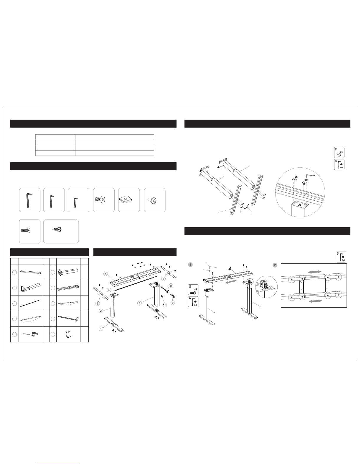
Tur n the l egs (2, 3) upsi de down . Att ach t he feet ( 1) to the b ottom o f the leg s using 8 pcs M8x 16mm
bol ts (F) an d tight en with 5 x5 hex ke y (A).
43. 3" - 70.9 "
(110 0 - 18 00m m)
3
3
2
1
F
A
A
F
A
G
Att ach the l egs (2, 3 ) to the cr oss bar ( 4) usin g 4pcs of t he M8x3 5mm bol ts (G). U se the 5x 5 hex key
to lo ck bolt s firml y in plac e. Then , us ing t he 4x4 he x key (B) , adjus t the 8 scr ews on th e botto m of the
cro ss bar (4 ) so that t hey wil l accom modat e the act ual siz e of your w ork sur face.
2
Not e:
Tig hte n those s crews i n case of t he
cro ss bar sa gged.
Page 3
Step 3
04
Step 4
05
Step 5
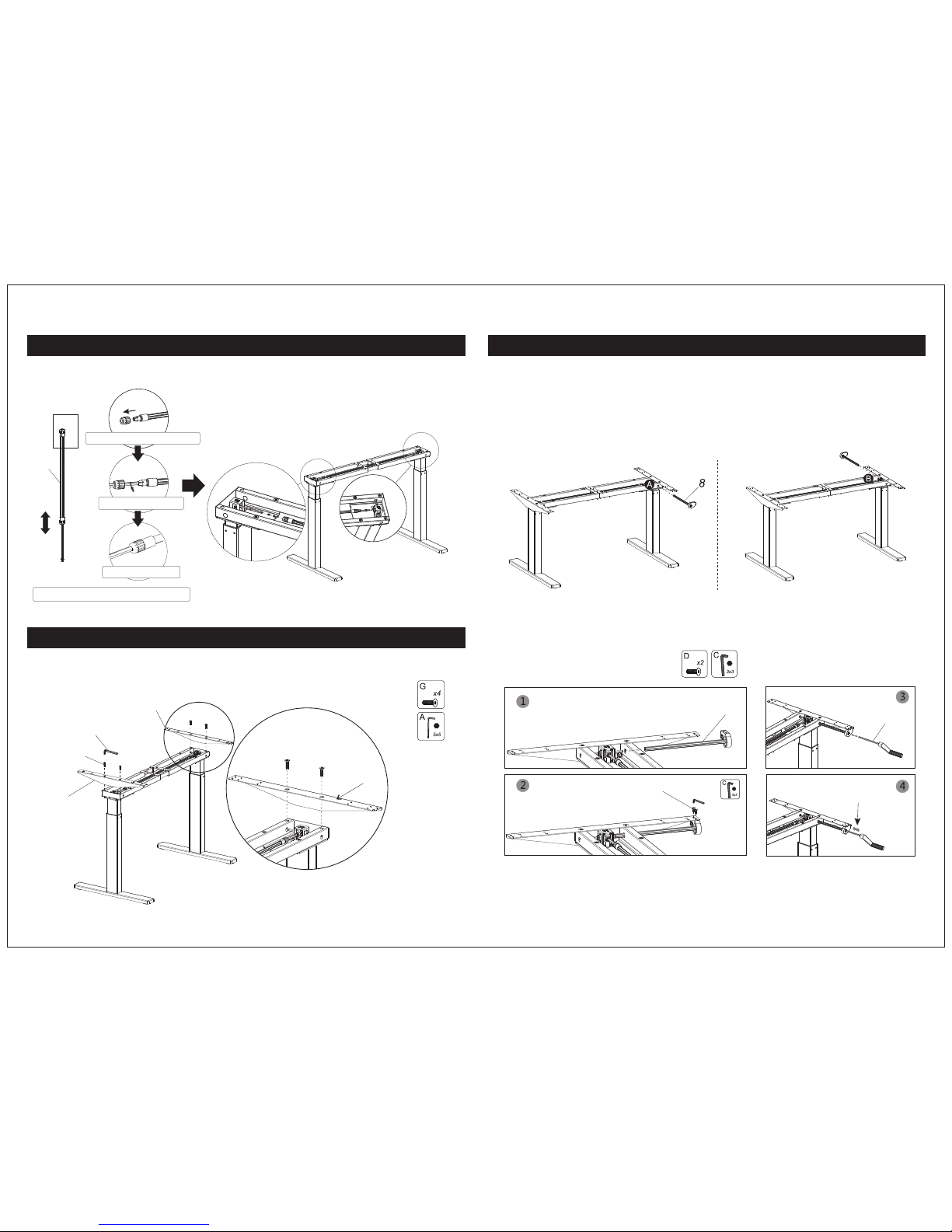
Ins ert the c rank sh aft (8) i nto the r ight le g which h as a shaf t hole, u sing 2p cs bolt s (D) and l ock fir mly
wit h hex key ( C).
The n inser t crank h andle ( 9) into c rank sh aft (8) .
9
8
D
C
6
7
A
G
7
Usi ng the he x key (A) , conne ct both t he left a nd righ t side br acket s (6, 7) to t he bott om legs
usi ng 4 bolt s (G).
Ple ase not e:
Do no t mispl ace the t wo brac kets (6 , 7).
Sli ghtly l oosen t he adju stabl e nuts to a djust t he leng th of the d rive sh aft (5) . Inser t the ass emble d
dri ve shaf t into th e slots t hat loc ated at t he top of e ach leg .
Loo sen the a djust able nu t
Ins ert to th e slots
Tig hte n the nut
Adj ust the l ength o f drive s haft
5
Page 4
06 07
Step 6 Step 7
10
H
H
6
7
E
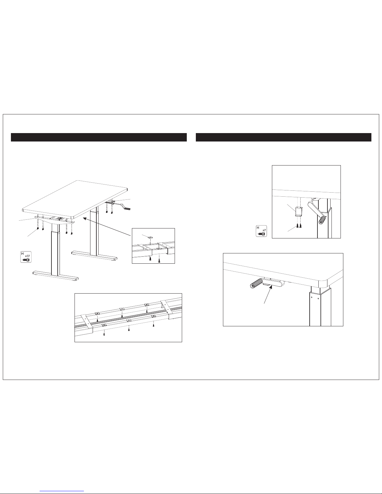
Eve nly pla ce the wo rk surf ace ont o the leg s then at tach it t o the sid e brack ets (6, 7 ) using
scr ews (H) . Tig hte n screw s firml y with a dr ill or sc rewdr iver.
Att ach the c rank ha ndle ho lder (1 0) to the u nders ide of th e table t op usin g 2 screw s (H). En sure
tha t the cra nk hand le will p roper ly sett le onto t he hold er when p ushed i n befor e screw ing cra nk
han dle hol der (10 ) to surf ace.
Pla ce the cr ank her e after y ou use.
Use t he gask ets (E) w hile sc rew the c ross ba r (4),
usi ng gask et (E) qu antit y depen ds on the l ength
of yo ur desk top.
 Loading...