

Page 1
RV-8 70cc FLS
ARF and ARFSV
Instruction Manual
Page 2

BEFORE CONTINUING WITH THIS INSTRUCTION MANUAL OR THE ASSEMBLY OF YOUR
AIRCRAFT, PLEASE VISIT OUR WIKI SUPPORT SITE FOR THE LATEST PRODUCT UPDATES,
FEATURE CHANGES AND MANUAL ADDENDUMS FOR THIS PRODUCT.
wiki.flexinnovations.com/wiki/RV-8_70cc
Page 3

TABLE OF CONTENTS
Introduction .............................................................................................................................. 1
Specifications: ................................................................................................................................................................. 1
Required Equipment: ................................................................................................................................................... 2
Optional Equipment: .................................................................................................................................................... 4
Hangar 9®/Ultracote®/Oracover® Colors: ............................................................................................................... 4
Using this Manual ............................................................................................................................ 5
ARF .............................................................................................................................................. 7
Aileron and Flap Control Horn Installation ................................................................................. 7
Control Horn Installation ............................................................................................................................................ 7
Hinge Installation: .......................................................................................................................................................... 9
Main Wing Servos and Linkages Installation ........................................................................... 10
Ailerons ........................................................................................................................................................................... 10
Flaps ................................................................................................................................................................................. 12
Elevator Installation ...................................................................................................................... 13
Control Horn Installation ......................................................................................................................................... 14
Hinge Installation: ....................................................................................................................................................... 14
Elevator Servo and Linkage Installation ................................................................................... 15
ARF and ARFSV ....................................................................................................................... 18
Rudder, Tailwheel Installation .................................................................................................... 18
Tail Wheel Installation ............................................................................................................................................... 18
Rudder and Rudder Control Horn Installation ................................................................................................. 20
Rudder Hinge Installation ........................................................................................................................................ 21
Rudder Control Horn Installation .......................................................................................................................... 22
Rudder Servo and Linkage Installation ..................................................................................... 24
Push/Pull System, Servo Installed in the Vertical Fin ..................................................................................... 24
Installing the Vertical Fin ............................................................................................................. 27
Pull/Pull System ........................................................................................................................................................... 29
Push/Pull System, Servo Installed in Fuselage ................................................................................................. 32
Mounting the Stab ........................................................................................................................ 34
Landing Gear Installation ............................................................................................................. 35
Engine and Throttle Servo Installation .............................................................................. 39
DA-70 Engine Installation ............................................................................................................ 39
DA-70 Throttle Servo and Throttle Linkage Installation ............................................................................... 41
DA-60 Engine Installation ............................................................................................................ 43
Throttle Installation .................................................................................................................................................... 45
Ignition Installation ....................................................................................................................... 48
Fuel Tank Installation .................................................................................................................... 50
Exhaust and Cowling Installation ............................................................................................... 53
Muffler Installation (A) .............................................................................................................................................. 53
Page 4

Canister Installation (B) ............................................................................................................................................. 56
Baffle and Final Cowling Installation ................................................................................................................... 59
Electric Power Setup ............................................................................................................. 63
Motor Installation .......................................................................................................................... 63
ESC Installation .............................................................................................................................. 65
Battery Tray Installation ............................................................................................................... 66
Motor/ESC Cooling ........................................................................................................................ 68
Final Assembly ....................................................................................................................... 69
Radio Installation ........................................................................................................................... 69
Wing Installation ............................................................................................................................ 72
Pilot Installation (Optional) ......................................................................................................... 75
Canopy Installation ....................................................................................................................... 76
Decal Installation ........................................................................................................................... 77
Final Setup and Flying Notes ............................................................................................... 84
Center of Gravity ............................................................................................................................ 84
Aura 8 Professional ........................................................................................................................ 85
Range Testing ................................................................................................................................. 86
Before First Flight .......................................................................................................................... 86
AMA Safety Code ........................................................................................................................... 87
Replacement Parts ......................................................................................................................... 88
Optional Accessories ..................................................................................................................... 89
Limited Warranty ................................................................................................................... 90
Page 5
RV-8 70cc FLS Instructions
Wingspan:
100 in. (2540 mm)
Length:
90 in. (2288 mm)
Gas Weight:
(DA-70 w/MTW TDH110 Canister)
23 lb. 3 oz. (10.5 Kg)
Electric Weight:
(Potenza 65cc w/12S 6200mAh)
24 lb. 15oz. (11.3 Kg)
Engine/Motor Size:
60-70cc
INTRODUCTION
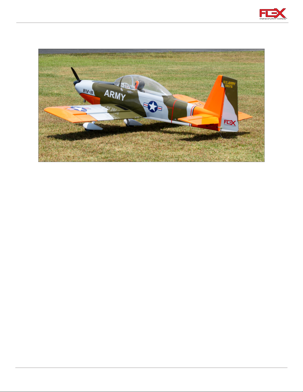
The RV-8 70cc FLS (Feather Light Series) is a 35% scale model of the famous experimental Van’s
Aircraft RV-8. Designer and World Champion Quique Somenzini has taken a completely new
approach with the design of the RV-8 70cc FLS. A massive airframe, with over 2000 square inches
(130.3 sq. dm.) of wing area, that comes in at 23 pounds (10.4 kg) flying weight, offers such an
incredibly lightly loaded airframe, it feels like you are flying something lighter than air. Couple the
extremely light wing loading with key design and geometric details from the master himself, and you
get an aircraft that has a huge flight envelope.
Along with the incredible airframe design of the RV-8 70cc FLS, it is also designed to accept multiple
power systems, including 60cc electric setups that allow you to fly anywhere from 5 to 8 minutes on
a typical 12S Li-Po setup! We also cannot forget about its float-ready airframe either! The optional RV8 70cc FLS Float Set includes everything needed to get it on the water and is also available to match
your RV-8 70cc FLS’ color scheme.
This is an airplane that you need to truly experience for yourself, and once you have, you’ll quickly
add one to your hangar! From its insane stability at walking speeds with the flaps down, to classic 3D
and precision aerobatic maneuvers, the RV-8 70cc FLS has the flight performance and versatility that
is for every pilot, of virtually every skill level.
Specifications:
1
Page 6

RV-8 70cc FLS Instructions
Transmitter:
8+ channels
Receiver:
8+ channels, high-voltage capable
Receiver Battery:
(2) 2S 4000mAh 15C+ LiPos (FPZBR40002S15 recommended)
Receiver Battery Strap:
(1) Flex Hook and Loop Strap, 300 mm long (FPMA1016)
Aileron, Flaps, Elevators Servos:
(6) Minimum 200 oz/in (14 kg/cm)
Potenza DS22209HV high voltage servos recommended.
Rudder Servo:
Minimum 400 oz/in (28 kg/cm)
Potenza DS494010HV brushless high voltage servo
recommended.
Aileron, Flaps, Elevators:
(6) 2-inch Single Arm
Potenza 2-inch Clamping Servo Arm – FPZA1036 recommended.
Rudder:
(Tail-mounted Push-Pull)
2-inch Single Arm
Potenza 2-inch Clamping Servo Arm – FPZA1036 recommended.
Rudder:
(Front-Mounted Pull-Pull)
4-inch Double Arm
Potenza 4-inch Clamping Servo Arm – FPZA1037 recommended.
Ailerons:
(2) 18-inch (460 mm)
Flaps:
(2) 9-inch (230 mm)
Flaps & Ailerons:
(To the receiver or Aura)
(2) 9-inch (230 mm)
Elevators:
(2) 48-inch (1220 mm)
Rudder:
(Tail-mounted Push-Pull):
48-inch (1220 mm)
Servo Extension Safety Clips:
Flex Servo Connector Safety Clips (FPZA1040)
Spinner:
5 inch (140 mm)
Falcon 5-inch Carbon Fiber Spinner – FPMFAL5CGS recommended
Required Equipment:
Radio Equipment & Servos:
Servo Arms:
Servo Extensions:
Spinner:
2
Page 7

RV-8 70cc FLS Instructions
Engine:
60cc to 70cc Gasoline two-stroke engine
Desert Aircraft DA-70 – FPMDA70 recommended
Exhaust:
Follow your engine manufacturer’s recommendation, as well as
local noise restrictions in your area.
DA stock muffler set by Slimline – FPMDA70MUFFLER
recommended for DA-70.
Other Exhaust Options:
MTW TDH110 Rear Discharge Canisters for the DA-70
KS 60 mm drop 2 to 1 header for the DA-70
KS86 Rear Discharge Canister for DA-60
MTW Flexible header 60 mm drop for DA-60
Propeller:
Follow your engine manufacturer’s recommendation.
Falcon Carbon Fiber 25x8W recommended for the DA-70
Engine Standoffs:
(4) 20 mm Aluminum Standoffs for DA-70
or
(4) 30mm Aluminum Standoffs for DA-60
FPM1624 recommended for DA-70
Throttle Servo:
High Quality, Metal Gear Digital Servo
Potenza DS22209HV high voltage servo recommended.
Throttle Servo Extension:
18-inch (460 mm)
Ignition Regulator:
Follow your engine manufacturer’s recommendation.
Ignition Strap:
Flex Hook and Loop Strap, 200mm long (FPMA1012)
Ignition Battery
2S 2000mAh 15C+ Li-Po
FPZBR20002S15 recommended
Ignition Battery Strap:
Flex Hook and Loop Strap, 200 mm long (FPMA1012)
Fuel Tank Strap?
(1) FPMA1014 (2) Battery Hook and Loop Strap Small 260mm Long
(1) FPMA1013 (2) Battery Hook and Loop Strap Small 220mm Long
Fuel Dot:
McFueler Fuel Dot (FPMAMCFUELER)
Motor:
60-70cc Brushless Motor Equivalent
Potenza High Performance 65cc 185KV Brushless Motor
FPZM65CC recommended.
ESC:
160A HV ESC
Castle Creations Phoenix Edge 160HV, 50V ESC recommended.
Flight Batteries:
2 x 6S 6200mAh Li-Pos
Potenza 6S 6200mAh 40C Li-Pos recommended.
Flight Battery Straps
(2) Flex Hook and Loop Strap, 300mm long (FPMA1016)
Gas Engine Setup
Electric Setup
3
Page 8

RV-8 70cc FLS Instructions
Propeller:
Follow your motor manufacturer's recommendation.
Mejzlik 25x12S recommended for the Potenza 65cc Brushless
Motor.
Motor Standoffs:
(4) 2-½ inch (63mm) Motor Standoffs
ESC Servo Extension:
18-inch (460 mm)
FPZAURA08PRO
Aura 8 Professional
FPM2019
24oz Lightweight Fuel/Smoke Tank (for smoke)
FPM1623
32oz Fuel Tank (larger tank for longer flight times)
FPMHOLYG2
Holy Smokes G2 Smoke System
FPM2014
Flex Innovations Premium Wing and Tail Bag Set
ISDTD2
ISDT D2 Dual Port AC 200W Charger
FPM2022
Premium Vinyl Graphics Set, RV-8 70cc FLS, Red Scheme (by Callie
Graphics)
FPM2023
Premium Vinyl Graphics Set, RV-8 70cc FLS, Camouflage Scheme
(by Callie Graphics)
FPMAMCFUELER
McFueler Fuel Dot
Ultracote®
Oracover®
Olive Drab (HANU904)
Olive Drab 21-018
Light Gray (HANU882)
Grey 210-011
Orange (HANU877)
Orange 21-060
White (HANU870)
White 21-010
Black (HANU874)
Black 21-071
Ultracote®
Oracover®
True Red (HANU866)
Ferrari Red 21-023
Midnight Blue (HANU885)
Dark Blue 21-052
Silver (HANU881)
Silver 21-091
White (HANU870)
White 21-010
Optional Equipment:
Hangar 9®/Ultracote®/Oracover® Colors:
Camouflage Scheme:
Red, White and Blue Scheme:
4
Page 9

RV-8 70cc FLS Instructions
USING THIS MANUAL
This manual is for both the ARF and ARFSV versions.
The manual is divided into sections to make the assembly of the airplane easier to follow.
If you have an ARFSV, many of the steps will be completed for you, however, it is important that you
read through this entire instruction manual to familiarize yourself with this aircraft.
Note: the squares “▢” next to each step that can be checked off to help you keep track of the steps
that have been completed.
ATTENTION
Read the ENTIRE instruction manual to become familiar with the features and assembly of the
product before assembly. Failure to assemble or operate the product correctly can result in damage
to the product, personal property and cause serious or fatal injury.
All instructions, warranties and other collateral documents are subject to change at the sole
discretion of Flex Innovations, LLC. For up-to-date product literature, please visit our website at
www.flexinnovations.com and navigate to the product page for this product.
WARNING
This is NOT a toy. This product is not intended for use by children under 14 years of age without
direct adult supervision.
IMPORTANT INFORMATION REGARDING WARRANTY
Please read our Warranty and Liability section before building this product. If you as the purchaser or
user are not prepared to accept the liability associated with the use of this product, you are advised
to return this product immediately in new and unused condition, in the original packaging material,
to the place of purchase.
SAFETY WARNINGS AND PRECAUTIONS
Protect yourself and others by following these basic safety guidelines.
1. This manual contains instructions for safety, operation, and maintenance. It is essential to
read and follow all the instructions in the manual, prior to assembly, setup, or use, in order to
operate correctly and avoid damage or serious injury.
2. In some cases, the written instructions may differ slightly from the photos. In those instances,
the written instructions should be considered correct.
3. This model is not a toy, rather it is a sophisticated hobby product and must be operated with
caution and common sense. This product requires some basic mechanical ability. Failure to
operate this product in a safe and responsible manner could result in injury, or damage to the
product, or other property.
4. This model must be assembled according to these instructions. Do not alter or modify the
model outside of these instructions provided by Flex Innovations, LLC, as doing so may
render it unsafe and/or unflyable. You must take time to build straight, true, and strong. It is
your responsibility to ensure the air worthiness of this product.
5. Use only compatible, appropriate components for the final assembly of this model. Ensure
that the radio system is in functional condition, that the engine is appropriately sized for the
model and that all other components are appropriate for use in this model as specified in this
5
Page 10

RV-8 70cc FLS Instructions
instruction manual. All components must be installed correctly so that they operate correctly
both on the ground and in the air.
6. Inspect and check operation of the model and all its components before every flight.
7. If you are not an experienced pilot, or have not flown a high-performance model before, it is
recommended that you seek assistance from an experienced pilot in your R/C club for your
first flights. If you're not a member of a club, the Academy of Model Aeronautics (AMA) has
information about clubs in your area whose membership includes experienced pilots.
8. Keep the propeller area clear from such items as loose clothing, jewelry, long hair, or tools, as
they can become entangled. Keep your hands and body parts away from the propeller as
injury can occur.
SPECIAL LANGUAGE DEFINITIONS
The following terms are used throughout the product literature to indicate various levels of potential
harm when operating the product.
NOTICE: Procedures, which if not properly followed, create a possibility of physical
property damage AND a liable or no possibility of injury.
CAUTION: Procedures, which if not properly followed, create a probability of physical
property damage AND a possibility of serious injury.
WARNING: Procedures, which if not properly followed, create the probability of property
damage, collateral damage and serious injury OR create a high probability of
serious injury.
IMPORTANT BEFORE ASSEMBLY
Carefully unpack your aircraft and inspect the parts. Review the manual and gather the required tools
and supplies.
o Remove all parts from their plastic bags, inventory all items and closely examine all the major
airframe components for damage. If any items are missing or you find damaged components,
do not proceed. Please contact customer support.
o Use a covering iron with a covering sock on high heat to tighten the covering as necessary,
paying special attention to the leading edges of the flying surfaces, hinge lines and stabilizer
and wing saddle areas. Apply slight pressure over sheeted areas to thoroughly bond the
covering to the wood. Use caution around seams to prevent inadvertently pulling them loose.
o Pro-Tip: You can use a “Seal-It Pen” to permanently seal any sharp edges or corners of
covering that may come loose in flight.
o Use thin CA to go over any important glue joints, such as the motor box, firewall, servo
mounting rails and any other pre-assembled joints that may see high stress during flight.
o Gather all required components such as motor and radio equipment that will be used to
equip the airplane. Create a new radio program in your transmitter and bind this model
program to the receiver that will be used in the airplane
o IMPORTANT NOTE:
The canopy is attached to the fuselage differently than you may have experienced with other
aircraft. To remove it, remove the two screws. Slide the canopy to the rear (DO NOT LIFT UP).
Once the canopy has been moved aft approximately 1/2-inch (12mm), lift at the rear and
continue moving the canopy to the rear as it is lifted away from the fuselage.
6
Page 11
RV-8 70cc FLS Instructions
Required for this section
Components
Tools
Adhesives/Building Materials
o Main Wing Panels (2)
o Aileron Control Horns (4)
o Aileron Control Horn
Base Plates (2)
o Flap Control Horns (4)
o Flap Control Horn Base
Plates (2)
o Aileron and Flap hinges
(16)
o Hobby Knife with a #11
blade
o Isopropyl Alcohol
o 30-minute Epoxy
o Petroleum Jelly
o Paper Towels
o Toothpicks
o Mixing Cups
o Mixing Sticks (something to
mix epoxy with)
!
ARF
If your airplane is the ARF version start building from this page through the end of this manual.
AILERON AND FLAP CONTROL HORN INSTALLATION
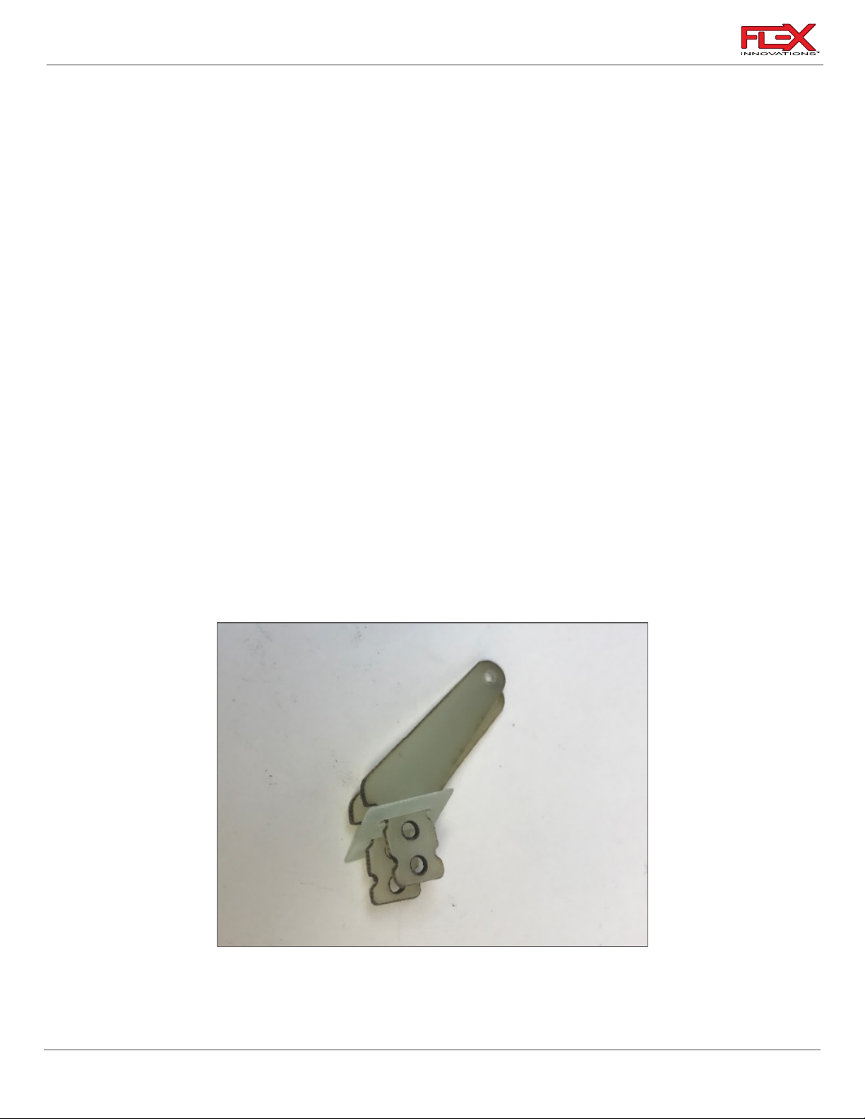
The flap and aileron control horns have been marked and bagged individually. It is especially
important that you use the correct control horns corresponding to each control surface.
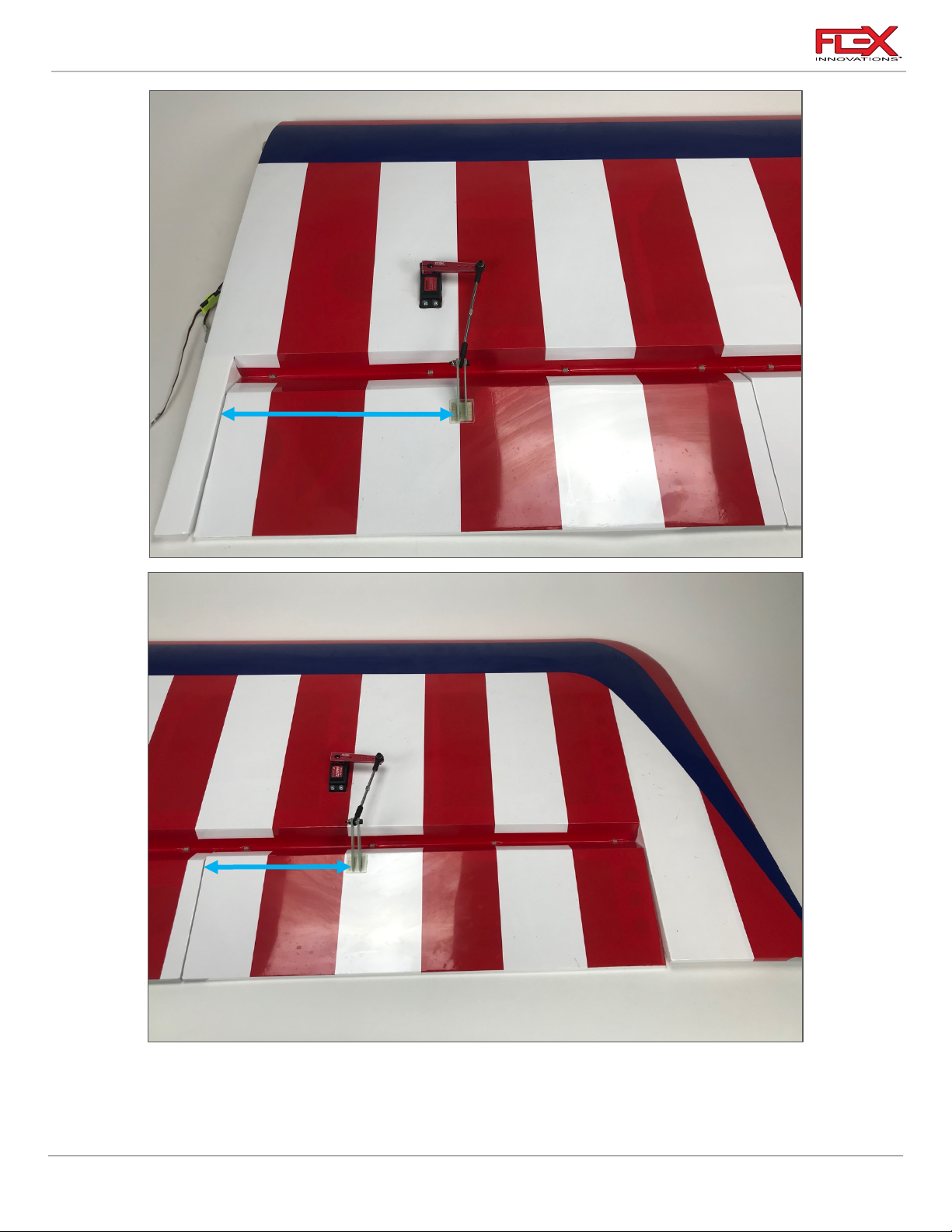
The Flap control horns do not align with the flap hinge line, rather they are offset towards the rear of
the wing, while the aileron control horns align with the aileron hinge line.
Control Horn Installation
1. Prepare the control horns by scuffing the portion of the control horn that is inserted into
the control surface with medium grit sandpaper. Use isopropyl alcohol and a paper towel
to clean the control horn and remove any debris left over after scuffing.
7
Page 12
RV-8 70cc FLS Instructions
!
210mm
160mm
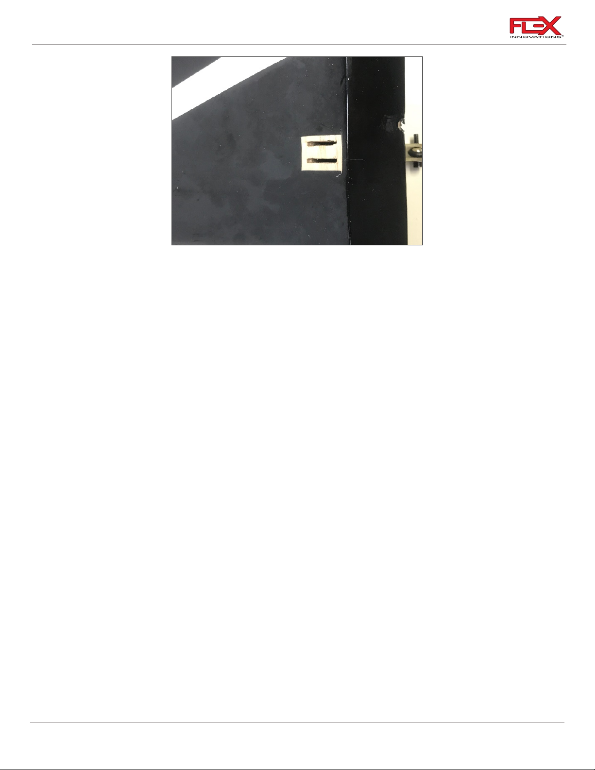
2. Locate the aileron and flap control horn slots. You can find them close to the front edge
of the control surface.
8
Page 13
RV-8 70cc FLS Instructions
!
!
!
!
!
!
!
!
3. Remove the covering using a hobby knife as shown in the picture above.
4. Mix an adequate amount of 30-minute epoxy. Apply epoxy to the slot in the control
surface as well as the control horns. Install the control horn and check for proper
alignment. Use isopropyl alcohol and a paper towel to clean up any excess epoxy before
it cures. Let it sit until the epoxy cures.
Quique’s Tip:
To ensure proper alignment of each control horn, you can secure the ball link to the horns and then
glue the horn in place with the ball link attached. This will ensure even alignment of both control
horns.
Hinge Installation:
1. Use a hobby knife to open holes in the covering for each hinge in the wings, ailerons and
flaps. Test fit the hinges. Check for minimal hinge gap and overall alignment.
2. Use medium grit sandpaper to scuff the portion of each hinge that is inserted into the
wing, aileron or flap. Use isopropyl alcohol and a paper towel to clean the hinge and
remove any debris that may be left after scuffing.
3. Use a toothpick or cotton swab to apply a small amount of petroleum jelly to the pivot
point of each hinge. Do not apply petroleum jelly to the entire hinge. The petroleum jelly
is used to prevent glue from adhering to the pivot of the hinge, keeping the hinge
moving free.
4. Mix an adequate amount of 30-minute epoxy and apply epoxy to the hinge slots in the
aileron. Insert a hinge into each slot in the aileron. Check for proper alignment. Use
isopropyl alcohol and a paper towel to clean up any excess epoxy before it cures.
5. Repeat this process with the flaps.
6. Repeat this process for gluing the hinges to the wing. Use masking tape or equivalent to
hold the aileron and flaps in a neutral position. Make sure the hinge gap is as tight as
possible, while still allowing for proper control surface deflection. Wait at least 1 hour
before removing the tape and testing the control surfaces.
9
Page 14

RV-8 70cc FLS Instructions
Required for this section
Components
Tools
Adhesives/Building Materials
o Main Wing Panels (2)
o Aileron Linkage (2)
o Aileron Servos (2)
o Aileron Servo Arms (2)
o 18-inch (460 mm) Aileron
servo extensions (2)
o Flap Linkage (2)
o Flap Servos (2)
o Flap Servo Arms (2)
o 9-inch (230 mm) Flap
servo extensions (2)
o Ball Links (8)
o M3 x 15 Socket Head Cap
Screw (8)
o M3 Washer (16)
o M3 Lock Nut (8)
o #1 Phillips Screwdriver
o 2.5mm Hex Driver
o 5.5mm Nut Driver
o Thin CA
o Blue Thread Lock
o Servo Connector Safety Clip
!
!
!
!
!
MAIN WING SERVOS AND LINKAGES INSTALLATION
Ailerons
1. Use a #1 Phillips screwdriver to thread a servo mounting screw into each of the pre-cut
holes in the servo mounting rails in the wing. Remove the screw and apply a small
amount of thin CA to each of the holes to harden the threads cut by the screw. Do not
use CA accelerator. Let the CA fully cure before moving forward.
2. Secure an 18-inch (460 mm) servo extension to each of the Aileron servos. Use Flex Servo
Connector Safety Clips (FPZA1040), heat shrink tubing or thread to secure the
connection.
3. Insert the aileron servo into the servo bay with the output shaft towards the leading edge
of the wing. Be sure to route the servo lead out of the wing before mounting the servo.
Mount the servo to the wing using the servo mounting screws provided with your servos.
10
Be sure to install the servos with the long servo extensions in the outside servo openings
of the wing panels (aileron location) and not in the openings close to the root of the wing
panel where the flap servos will be installed.
4. Use your radio system to center your aileron servos. Install your aileron servo arm onto
the servo as close to parallel with the hinge line as possible. Apply blue thread lock to the
servo arm screw and fully tighten the screw. If your servo arms have output shaft
clamping screws, apply blue thread lock, and secure them in place at this time.
5. Using a pushrod with a length of 2-3/4 inches (70mm), assemble the aileron linkages so
that the total length from center of ball to center of ball is approximately 95mm. Final
length will be adjusted when centering the control surface. Note that the opposite ends
of each aileron linkage have opposite direction threads.
Page 15
RV-8 70cc FLS Instructions
!
!
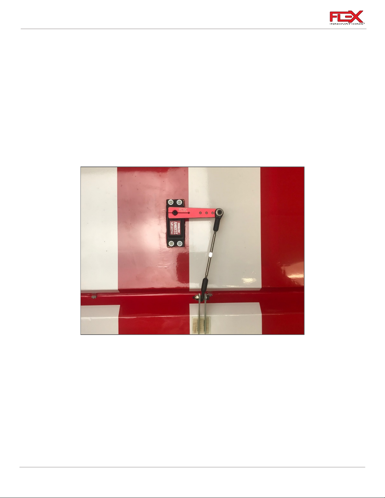
6. Attach the linkage to the servo arm. The correct hole location is 2-inches (50.8mm) from
center. If using the recommended 2-inch servo arm, this is the outermost hole.
7. With the radio powered-on and the servo centered with the arm parallel to the hinge line,
adjust the linkage length so that the control surface is centered. When satisfied with the
length of the linkage, secure the linkage to the control horn with the hardware in the
following order:
o M3x15 Socket Head Cap Screw
o M3 Washer
o Control Horn (Side 1)
o Ball Link
o Control Horn (Side 2)
o M3 Washer
o M3 Lock Nut
After the steps above are completed and the servo and linkages are installed, the assembly should
appear as shown in the picture above. Both ailerons should appear the same but mirrored
accordingly.
Note: The angle of the linkage is correct. As the servo arm rotates and the control surface deflects,
the linkage will straighten.
11
Page 16

RV-8 70cc FLS Instructions
!
!
!
!
!
!
!
Flaps
1. Use a #1 Phillips screwdriver to thread a servo mounting screw into each of the pre-cut
holes in the servo mounting rails in the wing. Remove the screw and apply a small
amount of thin CA to each of the holes to harden the threads cut by the screw. Do not
use CA accelerator. Let the CA fully cure before moving forward.
2. Secure a 9-inch (230mm) servo extension for to two of the Flap servos. Use Flex Servo
Connector Safety Clips (FPZA1040), heat shrink tubing or thread to secure the
connection.
3. Insert the Flap servo into the servo bay with the output shaft towards the leading edge of
the wing. Be sure to route the servo lead out of the wing before mounting the servo.
Mount the servo to the wing using the servo mounting screws provided with your servos.
4. Use your radio system to center your flap servos. Install your flap servo arm onto the
servo as close to parallel with the hinge line as possible. Apply blue thread lock to the
servo arm screw and fully tighten the screw. If your servo arms have output shaft
clamping screws, apply blue thread lock, and secure them in place at this time.
5. Using a pushrod with a length of 3.5 inches (90mm), assemble the flap linkages so that
the total length from center of ball to center of ball is approximately 112mm. Note that
the opposite ends of each flap linkage have opposite direction threads.
6. Attach the linkage to the servo arm. The correct hole location is 2-inches (50.8mm) from
the center of the servo arm. If using the recommended 2-inch servo arm, this is the
outermost hole.
Quique’s Tip:
In order to get the best performance out of the RV-8 70cc FLS, I recommend the use of a Live Wing,
which mixes the flap servos with the ailerons to get a full-span aileron. The flap surface and servo
centering is different than in traditional flap setups, so be sure to follow the next steps closely.
7. With the radio powered on and the servo centered with the arm parallel to the hinge line,
adjust the linkage length so that the flap is even with the aileron at its neutral position.
This will allow for the flap to travel in both up and down directions. When satisfied with
the length of the linkage, secure the linkage to the control horn with the hardware in the
following order:
o M3x15 Socket Head Cap Screw
o M3 Washer
o Control Horn (Side 1)
o Ball Link
o Control Horn (Side 2)
o M3 Washer
o M3 Lock Nut
12
Page 17
RV-8 70cc FLS Instructions
Required for this section
Components
Tools
Adhesives/Building Materials
o Elevator Control Horn (4)
o Control Horn Base (2)
o Left and Right Horizontal
Stabs
o Hobby Knife with a #11
Blade
o Isopropyl Alcohol
o 30-Minute Epoxy
o Paper Towels
o Mixing Cups
o Mixing Sticks
o Toothpicks
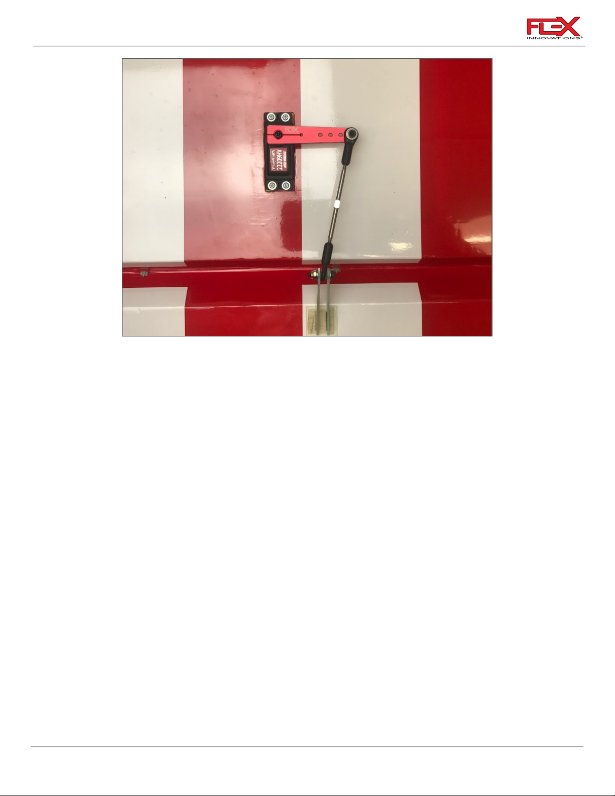
After these steps are completed and the linkages are installed, the assembly should appear as shown
in the above picture. Both flaps should appear the same, though mirrored on their respective sides.
Note: The angle of the linkage is correct. As the servo arm rotates and the control surface deflects,
the linkage will straighten.
ELEVATOR INSTALLATION
13
Page 18
RV-8 70cc FLS Instructions
!
!
!
!
!
35mm
Control Horn Installation
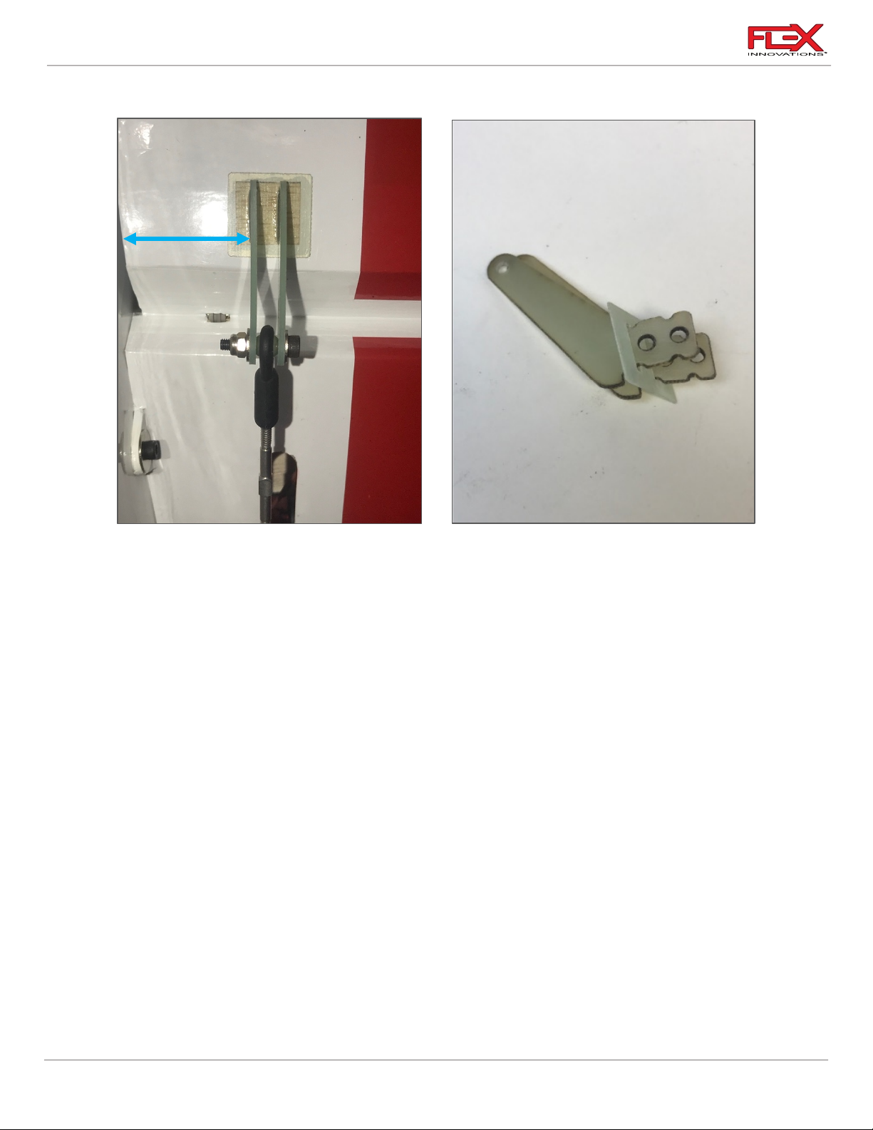
1. Use a hobby knife with a #11 blade to remove the covering from the bottom side of the
elevators. The control horn slots are approximately 1-1/8-inches (35mm) from the
elevator edge as shown in the picture.
2. The elevator horns are bagged and marked. Prepare the control horns by scuffing the
portion of the control horn the extends into the control surface with medium grit
sandpaper. Use isopropyl alcohol and a paper towel to clean the control horn and
remove any excess debris left after scuffing.
3. Mix an adequate amount of 30-minute epoxy. Apply epoxy to the control horn slots in
the elevator as well as the control horn. Push the control horns into the slot, being sure to
wipe away any excess epoxy with isopropyl alcohol and a paper towel.
Quique’s Tip:
To better help align the control horns with one another, use the provided hardware to secure the
control horns to the ball link. This will keep them aligned while they are glued in place.
Hinge Installation:
1. Use a hobby knife to open holes in the covering for each hinge in the horizontal stabs
and elevators. Test fit the hinges. Check for minimal hinge gap and overall alignment.
2. Use medium grit sandpaper to scuff the portion of each hinge that is inserted into the
horizontal stabs or elevators. Use isopropyl alcohol and a paper towel to clean the hinge
and remove any debris that may be left after scuffing.
14
Page 19

RV-8 70cc FLS Instructions
!
!
!
Required for this section
Components
Tools
Adhesives/Building Materials
o Horizontal Stabilizer
Assemblies (2)
o Horizontal Stabilizer
Carbon Fiber Tube
o Fuselage
o Elevator Servo (2)
o Elevator Servo Arm (2)
o 48-inch (1250mm) Servo
Extension (2)
o Left and Right Horizontal
Stabs
o M3x15 Socket Head Cap
Screw (8)
o M3 Washer (8)
o M3x12 Washer (4)
o M3 Lock Nut (4)
o 2.5mm Hex Driver
o 5.5mm Nut Driver
o #1 Phillips Screwdriver
o Servo Connector Safety Clip
!
3. Use a toothpick or cotton swab to apply a small amount of petroleum jelly to the pivot
point of each hinge. Do not apply petroleum jelly to the entire hinge. The petroleum jelly
is used to prevent glue from adhering to the pivot of the hinge, keeping the hinge
moving free.
4. Mix an adequate amount of 30-minute epoxy and apply epoxy to the hinge slots in the
elevator. Insert a hinge into each slot in the elevator. Check for proper alignment. Use
isopropyl alcohol and a paper towel to clean up any excess epoxy before it cures.
5. Repeat this process for gluing the hinges to the horizontal stabs. Use masking tape or
equivalent to hold the elevators in a neutral position. Make sure the hinge gap is as tight
as possible, while still allowing for proper control surface deflection. Wait at least 1 hour
before removing the tape and testing the control surfaces.
ELEVATOR SERVO AND LINKAGE INSTALLATION
1. Use a #1 Phillips screwdriver to thread a servo mounting screw into each of the holes in
the servo mounting rails in the horizontal stabilizer. Remove the screw and apply a small
amount of thin CA to each of the holes to harden the threads cut by the screw. Let the CA
fully cure before moving forward.
15
Page 20
RV-8 70cc FLS Instructions
!
!
!
!
!
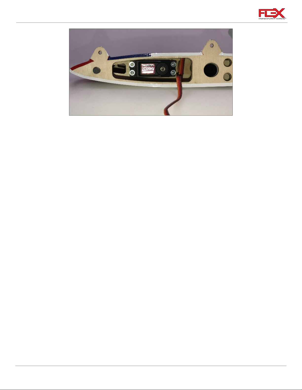
2. Insert the elevator servo into the mounting location with the output shaft towards the
horizontal stab tube. Mount the servo to the stab using the mounting screws provided
with your servos. Note that the servo wire will exit on the stab tube side of the servo.
3. Power on your radio system to center the servo. Install a 2-inch (51mm) servo arm onto
the servo. Apply a small amount of blue thread lock to the servo arm screw and secure it
in place. If your servo arm has clamping screws, apply blue thread lock to these screws
and secure them in place. Note that you may need to power off the model and rotate the
servo arm by hand to have access to each clamping screw.
4. Using a pushrod of 2 1/8-inch (55mm) length, assemble the elevator linkages and ball
links so that the total length from center of ball to center of ball is approximately 3-1/8inches (78mm). Final length will be adjusted when centering the control surface. Note
that both ends of the elevator linkages have opposite direction threads.
5. Attach the linkage to the servo arm. The correct hole location is 1 3/4-inches (44mm)
from the center of the servo arm. If you are using the recommended servo arm, this is the
second hole from the outside. The order of hardware components, starting from the top
of the servo is as follows:
o M3x15 socket head cap screw
o M3 washer
o Ball Linkage
o Servo Arm
o M3 washer
o M3 locknut
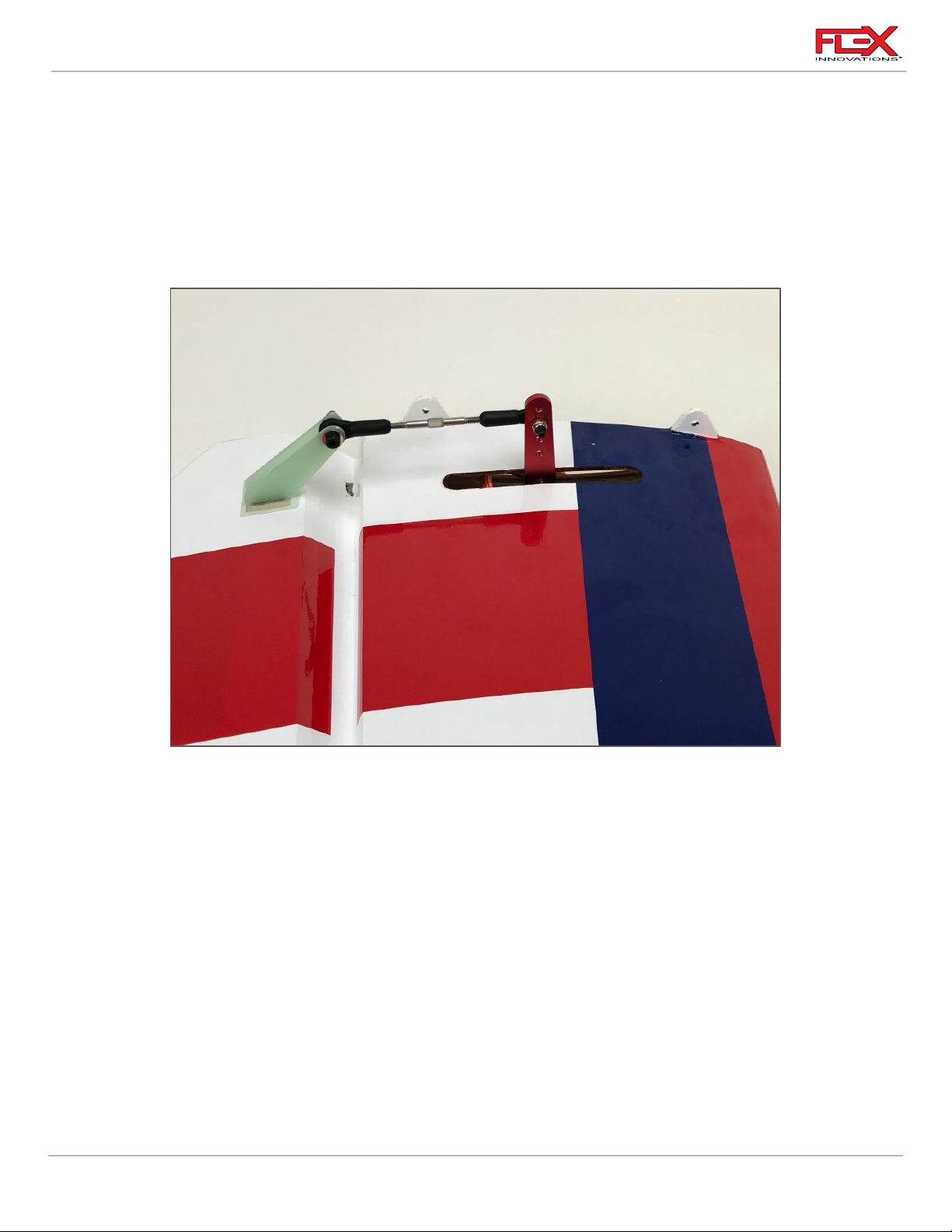
6. Attach the linkage to the control horn. The order of hardware components, starting from
the tip of the stabilizer is as follows:
o M3x15 socket head cap screw
o M3 washer
o Control Horn #1
o Ball Linkage
o Control Horn #2
o M3 washer
o M3 locknut
16
Page 21
RV-8 70cc FLS Instructions
!
!
7. With the radio powered on and the servo arm centered perpendicular to the servo case,
adjust the linkage length so that the control surface is centered.
Quique’s Tip:
For elevator centering, it is best to install the stabilizers onto the fuselage and stand approximately
10 feet (3m) behind the aircraft while sighting the two elevator halves. Using this method, you can
best align the most important part of the control surface, the widest part, rather than referencing
something less important, like the elevator counterbalance.
8. After installation is complete, your linkage setup should match the image above. Repeat
the same procedure for the other horizontal stabilizer.
17
Page 22
RV-8 70cc FLS Instructions
Required for this section
Components
Tools
Adhesives/Building Materials
o Tailwheel M3 Washer
(X2)
o Rudder
o Tailwheel Wire
o Tailwheel Bracket
o Tail wheel
o Lock Collar (2)
o Flat File
o 1.5mm Hex Driver
o 30-Minute Epoxy
o Blue Thread Lock
o Epoxy Mixing Cups
o Low-Tack Masking Tape
o Isopropyl Alcohol
o Paper Towels
o Mixing Sticks
!
!
ARF AND ARFSV
If your airplane is an ARFSV you can start from this page.
However, for instructions on the assembly of the aileron, flap and elevator pushrods, please
reference the ARF steps on pages 7 through 17.
RUDDER, TAILWHEEL INSTALLATION
Tail Wheel Installation
1. Scuff the fiberglass half hinge to prepare it for installation. Clean both the wire and half
hinge with a paper towel and isopropyl alcohol before proceeding.
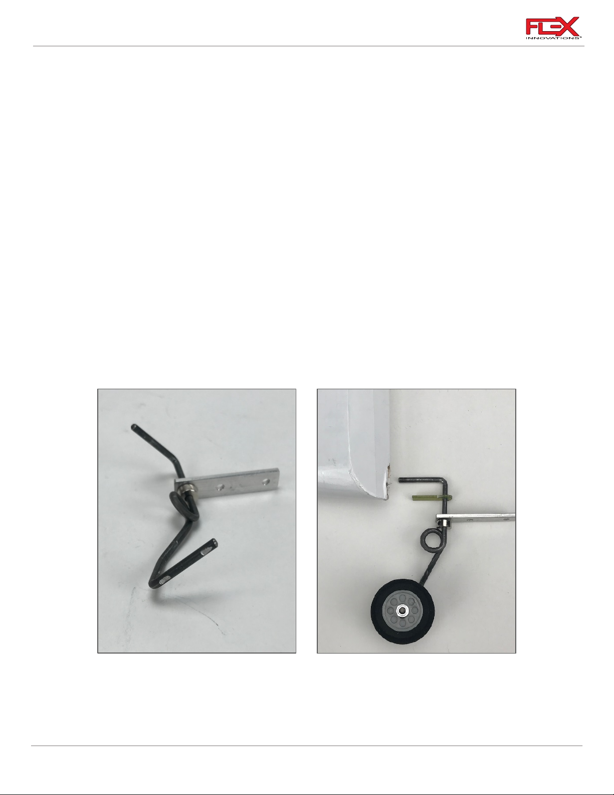
2. The aluminum tail wheel bracket has 3 holes. 2 are slightly smaller than the other.
Assemble the tail wheel wire and bracket by routing the L bend side of the wire through
18
Page 23
RV-8 70cc FLS Instructions
!
!
!
the largest hole in the aluminum bracket. The large hole is just big enough to fit the wire
through it. It may be snug, but do not drill out this hole as it is important to keep this
tolerance tight for the longevity of your tail wheel bracket. Slide the fiberglass half hinge
over the L bend side of the tail wheel wire.
3. Use a file to make two small flat spots on the inside and outside of the tail wheel wire for
the lock collar set screws
4. Finish the tail wheel bracket assembly by sliding a M3 wheel collar onto the tail wheel
axle with the flange facing the wheel location. Apply blue thread lock to a setscrew and
secure the wheel collar to the tail wheel wire. Apply a drop of light oil on the axle and
slide the tail wheel onto the axle. Install another wheel collar, with the flange facing the
tail wheel, and use blue thread lock when securing the set screw in place. Be sure the
collars are spaced so that the tailwheel spins freely.
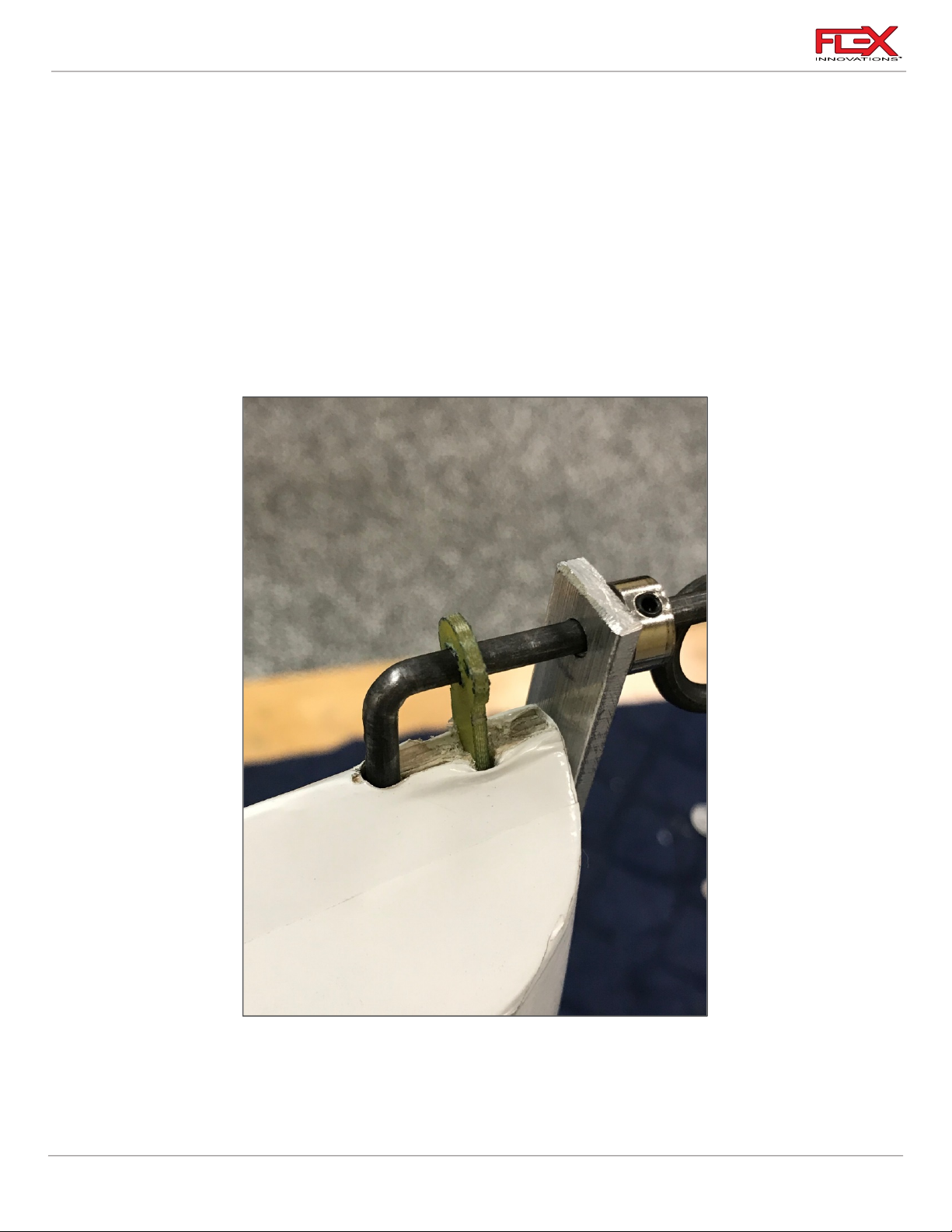
5. Mix an adequate amount of 30-minute epoxy. Hold the rudder with the leading edge up
and apply the epoxy to the tail wheel wire hole, as well as the slot for the half hinge.
Insert the wire and half hinge fully into their holes. Use isopropyl alcohol and a paper
towel to clean up any excess epoxy. Let these parts dry for at least 1 hour before
continuing with the rudder installation.
19
Page 24

RV-8 70cc FLS Instructions
Required for this section
Components
Tools
Adhesives/Building Materials
o Rudder hinges (3)
o Hobby Knife with a #11
blade
o Isopropyl Alcohol
o 30-minute Epoxy
o Mixing Cups
o Mixing Sticks
o Paper Towels
o Petroleum Jelly
Rudder and Rudder Control Horn Installation
Quique’s Tip:
The RV-8 70cc FLS has 3 different rudder servo locations. Two in the tail, and one in the cockpit area
for a pull-pull rudder setup.
The rudder servo position can greatly affect the center of gravity so you should select a servo
mounting positions that achieves the correct center of gravity to maintain the same flight
performance. For the lighter 60cc single cylinder engines, the front location for pull-pull must be
used for a proper CG. If you choose to use a 70cc twin cylinder engine, you can mount the rudder
servo in one of the two positions in the tail. If using any other type of engine, it’s recommended that
you do not install the rudder servo until you have the rest of the airplane complete and can check CG
to see where the best place for the servo should be.
The two tail-mounted rudder servo locations are located above and below the horizontal stabilizer.
The location below the horizontal stabilizer helps hide the servo and linkage better, but the
downside is that it requires you to disconnect the servo linkage if you want to remove the vertical fin
for transport or storage. The second location above the horizontal stabilizer makes removal and
transport easier, as the servo is mounted in the removable section of the vertical fin, but the servo
and linkage are more visible. Choose the location that fits your needs best!
20
Page 25
RV-8 70cc FLS Instructions
!
!
!
!
!
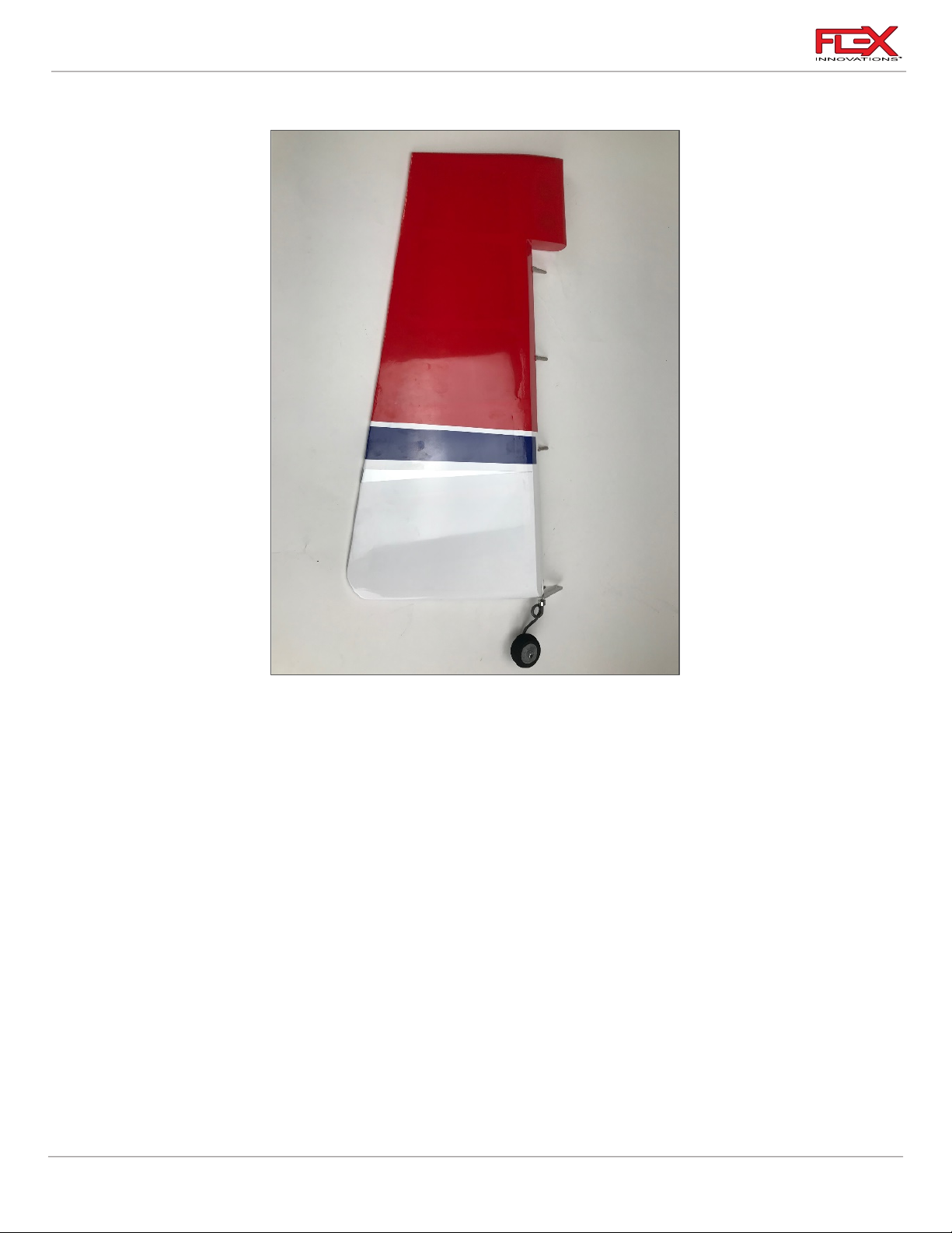
Rudder Hinge Installation
1. Locate the rudder and the vertical fin. Use a hobby knife to open holes in the covering for
each hinge in the rudder and the fin. Test fit the hinges. Check for minimal hinge gap and
overall rudder alignment.
2. Use medium grit sandpaper to scuff the portion of each hinge that is inserted into the
fuselage or rudder. Use isopropyl alcohol and a paper towel to clean any debris that may
be left on the hinge after scuffing.
3. Use a toothpick or cotton swab to apply a small amount of petroleum jelly to the pivot
point of each hinge. Do not apply petroleum jelly to the entire hinge. The petroleum jelly
is used to prevent glue from adhering to the pivot of the hinge, keeping the hinge
moving free.
4. Mix an adequate amount of 30-minute epoxy and apply epoxy to the 3 hinge slots in the
rudder. Insert a hinge into each hinge slot in the rudder, while being sure to check for
proper hinge orientation and alignment. Use isopropyl alcohol and a paper towel to
clean up any excess epoxy before it cures.
5. Repeat this process for gluing the hinges to the fin. Use low-tack masking tape to hold
rudder tight against the fin in its neutral position. Make sure the hinge gap it is as
minimal as possible, while still allowing for full travel of the rudder. Wait for at least 1
hour to remove the tape and move the control surface.
21
Page 26
RV-8 70cc FLS Instructions
!
!
!
40mm
210mm
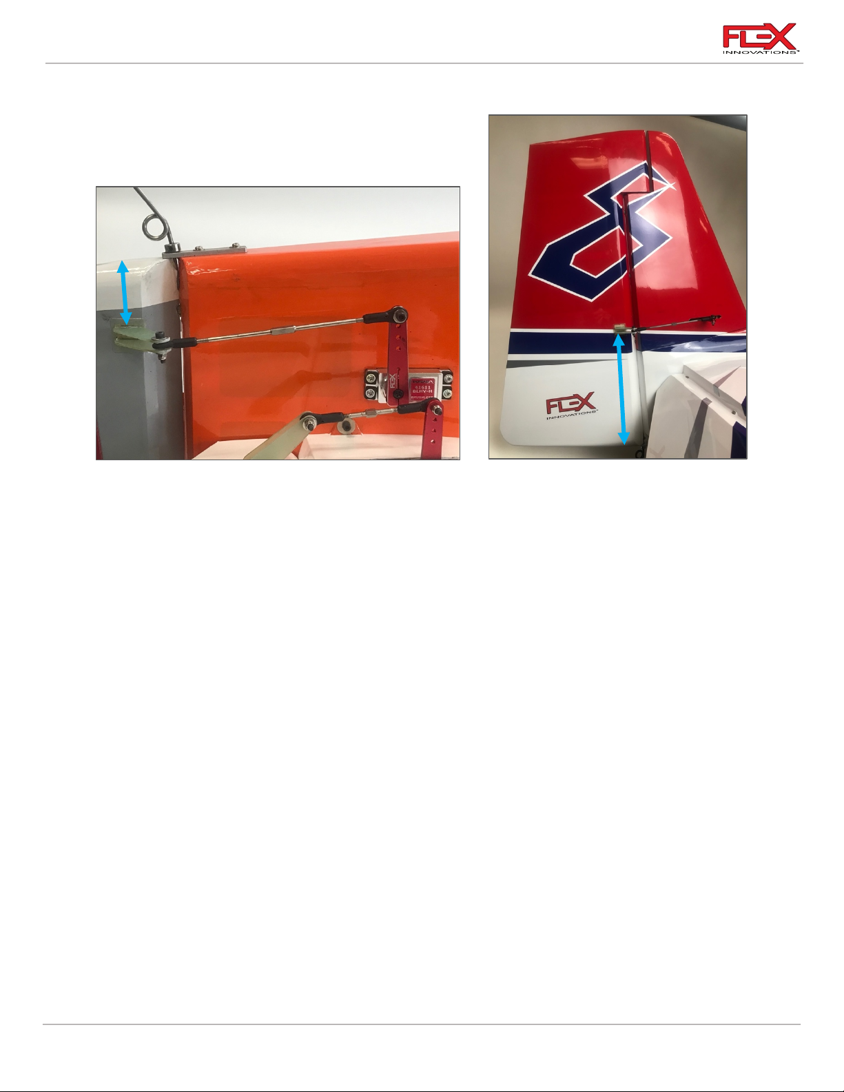
Rudder Control Horn Installation
1. There are two control horn locations for the rudder depending on your setup. If using the
pull-pull rudder setup, remove the covering from BOTH sides of the upper control horn
slots. If using a push-pull rudder setup, remove covering ONLY from ONE SIDE of the
control horn slot at your chosen location.
2. At the correct location matching your rudder servo installation use a hobby knife with a
#11 blade to remove the covering from the appropriate side(s) of the rudder to expose
the mounting slots for the control horn(s).
3. The Rudder control horns are marked. They are marked as follows:
“Pull”: To be used with the Pull/Pull cable installation. Total of 4 control horns; two
horns for the left side and two horns for the right side in the upper rudder spot,
40mm from the bottom edge as shown in the picture on the left.
“Fin”: To be used with the servo mounted in the fin. Total of two control horns. These
two control horns are installed on the right side of the rudder in the higher
location. 210mm from the bottom edge as shown in the picture on the right.
“Rud”: To be used with the servo mounted in the side of the fuselage under the
horizontal stabilizer. Total of two control horns. They can be installed on the right
or left side as the airplane has both right and left side rudder servo trays. These
horns are installed 40mm from the bottom edge of the rudder as shown in the
picture on the left.
22
Page 27
RV-8 70cc FLS Instructions
!
!
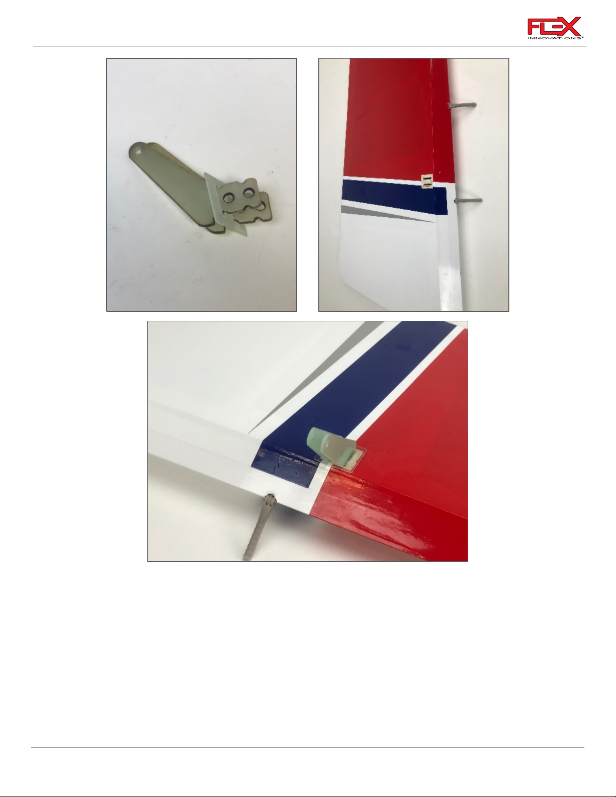
4. Prepare the control horns of your choice by scuffing the portion of the control horn the
extends into the control surface with medium grit sandpaper. Use isopropyl alcohol and a
paper towel to clean the control horns and remove any excess debris left after scuffing.
5. Mix an adequate amount of 30-minute epoxy. Apply epoxy to the control horn slots in
the rudder as well as the control horn. Push the control horns into the slot, being sure to
wipe away any excess epoxy with isopropyl alcohol and a paper towel.
Quique’s Tip:
To ensure proper alignment of each control horn, you can secure the ball link to the horns and then
glue the horn in place with the ball link attached. This will ensure even alignment of both control
horns.
23
Page 28
RV-8 70cc FLS Instructions
Required for this section
Components
Tools
Adhesives/Building Materials
o Vertical Fin assembly
Vertical Fin Carbon Fiber
Tube
o 48-inch (1220mm) Servo
Extension
o Fuselage
o M3x15 Socket Head Cap
Screw (4)
o M3 Washer (4)
o Hobby Knife with a #11
blade
o #1 Phillips Screwdriver
o 2.5mm Hex Driver
o Thin CA
o Blue Thread Lock
!
!
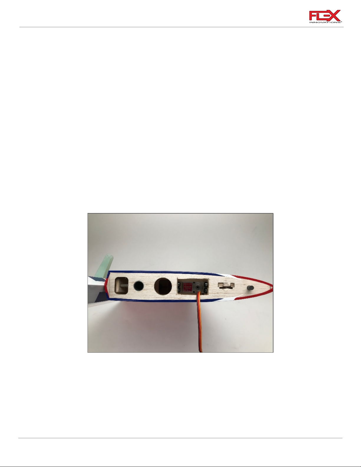
RUDDER SERVO AND LINKAGE INSTALLATION
Note: As mentioned on page 20, the RV-8 has three different locations for the installation of the
rudder servo. These options will be covered one by one. Skip the sections that are not
relevant to your installation but do not skip the section covering the installation of the vertical
fin.
Push/Pull System, Servo Installed in the Vertical Fin
1. Use a #1 Phillips screwdriver to thread a servo mounting screw into each of the pre-cut
holes in the servo mounting rails in the vertical fin. Remove the screw and apply a small
amount of thin CA to each of the holes to harden the threads cut by the screw. Let the CA
fully cure before moving forward.
2. Insert the Rudder servo into the mounting location with the output shaft towards the
leading edge of the vertical fin. Mount the servo to the stab using the mounting screws
provided with your servos. Note that the servo wire will exit toward the leading edge of
the vertical fin.
24
Page 29
RV-8 70cc FLS Instructions
!
!
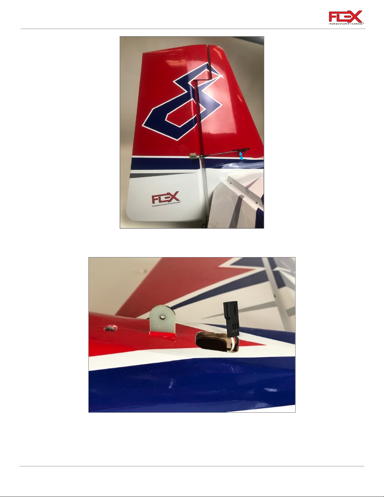
30mm
3. On the right side of the vertical fin, using a #11 blade, open the servo arm slot. This is
located 1 3/16 inches (30 mm) from the fin’s root.
4. Attach a 48-inch (1220mm) servo extension to the servo. Use Flex Servo Connector Safety
Clips (FPZA1040), thread or heat shrink tubing to secure the extension in place (note: if
you plan on removing the vertical fin for transport use a Flex Servo Connector Safety Clip,
25
Page 30

RV-8 70cc FLS Instructions
!
!
!
!
do not use heat shrink or thread). Route the servo extension through the holes in the
formers as shown in the picture above.
5. Power on your radio system to center the servo. Install a 2-inch (50.8mm) servo arm onto
the servo. Apply a small amount of blue thread lock to the servo arm screw and secure it
in place. If your servo arm has clamping screws, apply blue thread lock to these screws
and secure them in place. Note that you may need to power off the model and rotate the
servo arm by hand to have access to each screw.
6. Using a pushrod of 4-3/4-inches (120mm) in length, assemble the rudder linkage so that
the total length from center of ball to center of ball is approximately 5.7-inches (145mm).
Final length will be adjusted once the linkage has been attached to the servo and control
horn.
7. Attach the linkage to the servo arm. The correct hole location is 2-inches (50.8mm) from
the center of the servo arm. If you are using the recommended servo arm, this is the
outermost hole. The order of hardware components, starting from the top of the servo is
as follows:
o M3x15 socket head cap screw
o M3 washer
o Ball Linkage
o Servo Arm
o M3 washer
o M3 locknut
8. Attach the linkage to the control horn. The order of hardware components, starting from
the tip of the vertical fin is as follows:
o M3x15 socket head cap screw
o M3 washer
o Control Horn #1
o Ball Linkage
o Control Horn #2
o M3 washer
o M3 locknut
26
Page 31

RV-8 70cc FLS Instructions
!
Required for this section
Components
Tools
Adhesives/Building Materials
o Vertical fin Assemblies
o Vertical Fin Carbon Fiber
Tube
o M3x15 Socket Head Cap
Screw (3)
o M3 Washer (3)
o Hobby Knife with a #11
blade
o #1 Phillips Screwdriver
o 2.5mm Hex Driver
o Blue Thread Lock
!
9. With the radio powered on and the servo centered perpendicular to the servo case,
adjust the linkage length so that the rudder is centered.
INSTALLING THE VERTICAL FIN
1. Insert the carbon fiber vertical fin tube into the appropriate hole in the fuselage until it
bottoms out.
27
Page 32
RV-8 70cc FLS Instructions
!
!
!
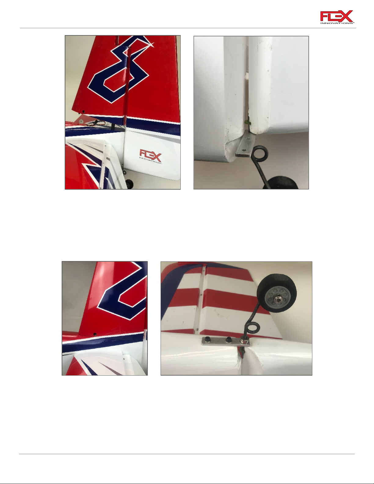
2. Partially install the vertical fin on the tube. Rotate the vertical fin on the tube
approximately 45 degrees away from its final installed position. Connect the servo lead to
the servo extension, and secure it in place using a Servo Connector Safety Clip
(FPZA1040). Continue sliding the vertical fin down onto the tube at the 45-degree angle.
Once the aluminum tailwheel bracket has passed the notch at the bottom of the
fuselage, you can rotate the fin to align it in line with the fuselage. Finish seating the
vertical fin fully, being sure to avoid pinching your rudder servo wires.
3. The vertical fin is secured in place by one M3 x 15 socket head cap screw and M3 washer
toward the leading edge of the vertical fin, and by two M3 x 10 socket head cap screws
and two M3 washers through the tailwheel bracket into the bottom of the fuselage.
Secure all three screws in place. If you do not plan on removing the vertical fin, use blue
thread lock when securing the screws.
4. Slide the lock collar up to the aluminum tailwheel bracket. Apply blue thread lock to the
set screw and fully tighten.
28
Page 33
RV-8 70cc FLS Instructions
Required for this section
Components
Tools
Adhesives/Building Materials
o Fuselage Assembly
o Rudder Servo
o 4-inch Double Servo Arm
o Wire Crimps (4)
o Pull-Pull Cable (2)
o Hobby Knife with a #11
blade
o #1 Phillips Screwdriver
o Thin CA
!
!
!
IMPORTANT
The aluminum tail wheel bracket and tailwheel wire are key structural elements and act like a hinge.
It is important that these parts are not modified or replaced and that the screws mounting the
bracket to the fuselage are not omitted.
Pull/Pull System
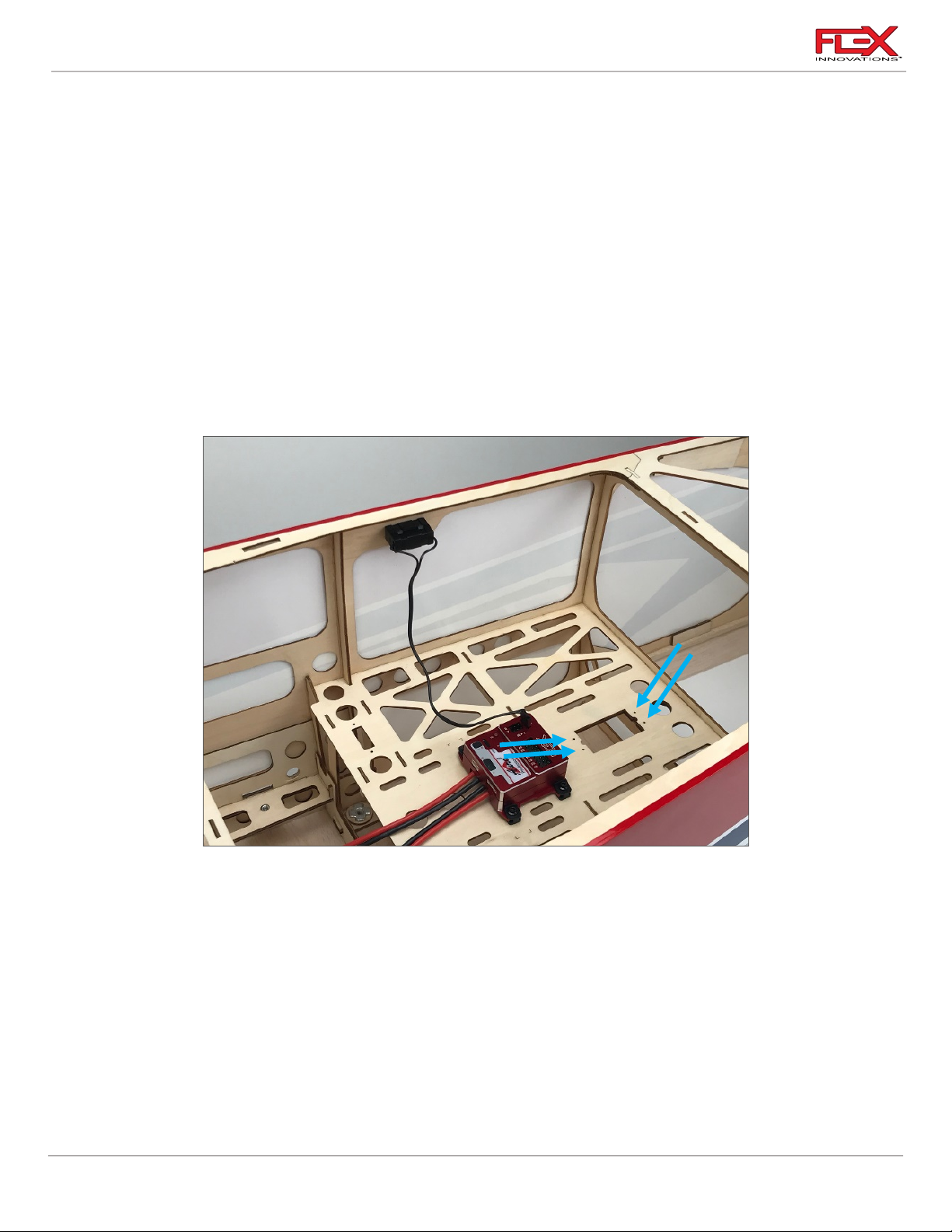
1. Use a #1 Phillips screwdriver to thread a servo mounting screw into each of the pre-cut
holes in the servo mounting location on the rudder servo tray inside the fuselage.
Remove the screw and apply a small amount of thin CA to each of the holes to harden
the threads cut by the screw. Let the CA fully cure before moving forward.
2. Insert the rudder servo into the rudder tray inside the fuselage with the output shaft
towards the nose of the airplane. Mount the servo to the tray using the screws provided
with your servo.
3. Center the servo using your radio system. Install the 4-inch servo arm so that is
perpendicular to the servo case. Apply a small drop of blue thread lock onto the servo
arm screw and secure it in place. If you are using a servo arm with clamping screws, apply
29
a drop of blue thread lock and secure them in place.
Page 34
RV-8 70cc FLS Instructions
!
!
Quique’s Tip:
You may find that the servo arm for pull-pull does not fit close to perpendicular to the servo case.
Since the RV-8 70cc FLS does not require a servo arm with an offset for pull-pull, try rotating the arm
180º to see if it fits closer to perpendicular when mounted in this orientation.
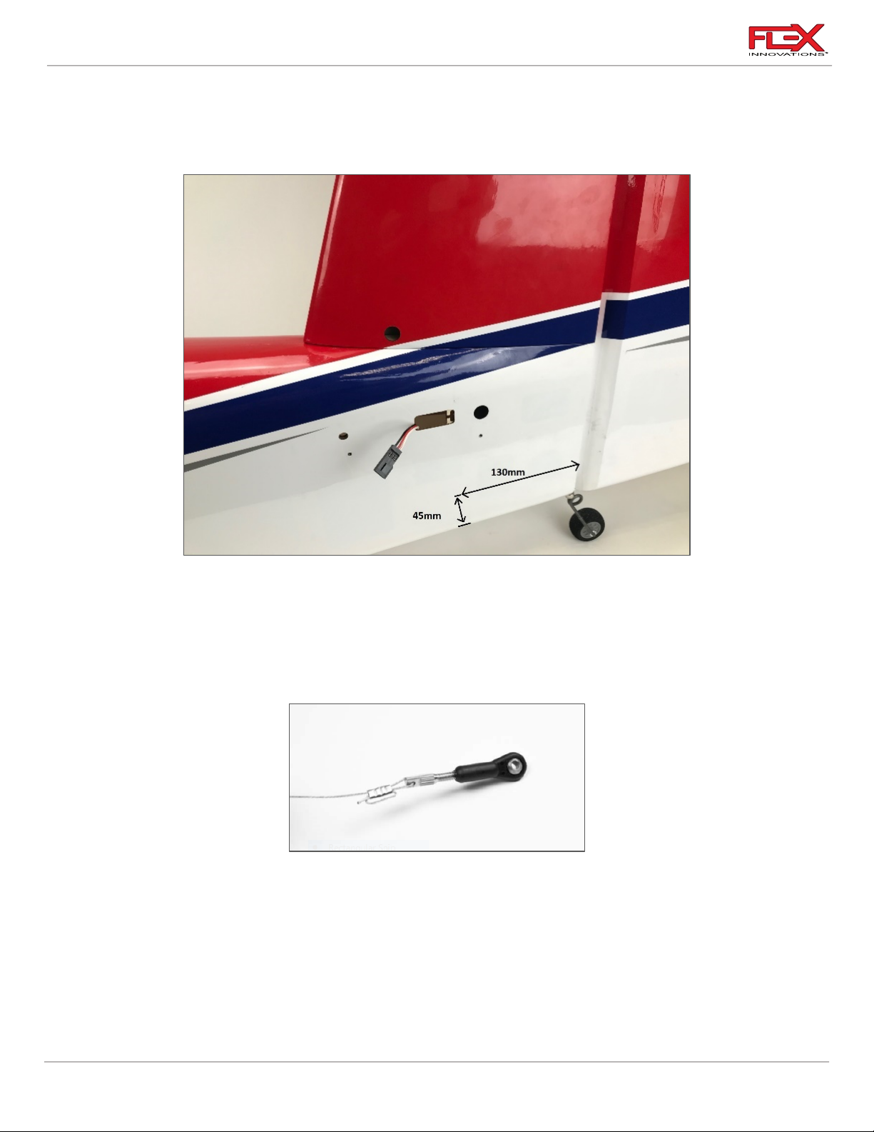
4. Locate the pull-pull cable exit holes in the rear of the fuselage. Use a hobby knife with a
#11 blade to remove the covering from the hole. The plastic tube guide is located
approximately 5-1/4-inches (130mm) from the rudder hinge line (see picture above). The
tube should run perpendicular to the rudder hinge line. With the canopy removed and
looking from the cockpit towards the tail you will see the nylon tube guides for the
cables.
5. Using pliers, thread a rigging coupler approximately halfway into a ball link. Take a
section of pull-pull cable and route it through a small piece of heat shrink tubing,
followed by a cable crimp. Then route the cable through the rigging coupler and back
through the crimp. For extra security, you can loop the cable around the crimp a final
time. Slide the crimp tight against the coupler and use a crimping tool to permanently
attach the cable. Apply a small amount of thin CA to aid in securing the cable and crimp.
Once secure, slide the heat shrink tubing back over the cable and crimp, and shrink it in
place. The shrink tubing is only used to keep the cables looking neat and prevent the wire
from snagging on any objects. Repeat this process for the second cable side.
30
Page 35
RV-8 70cc FLS Instructions
!
!
!
!
!
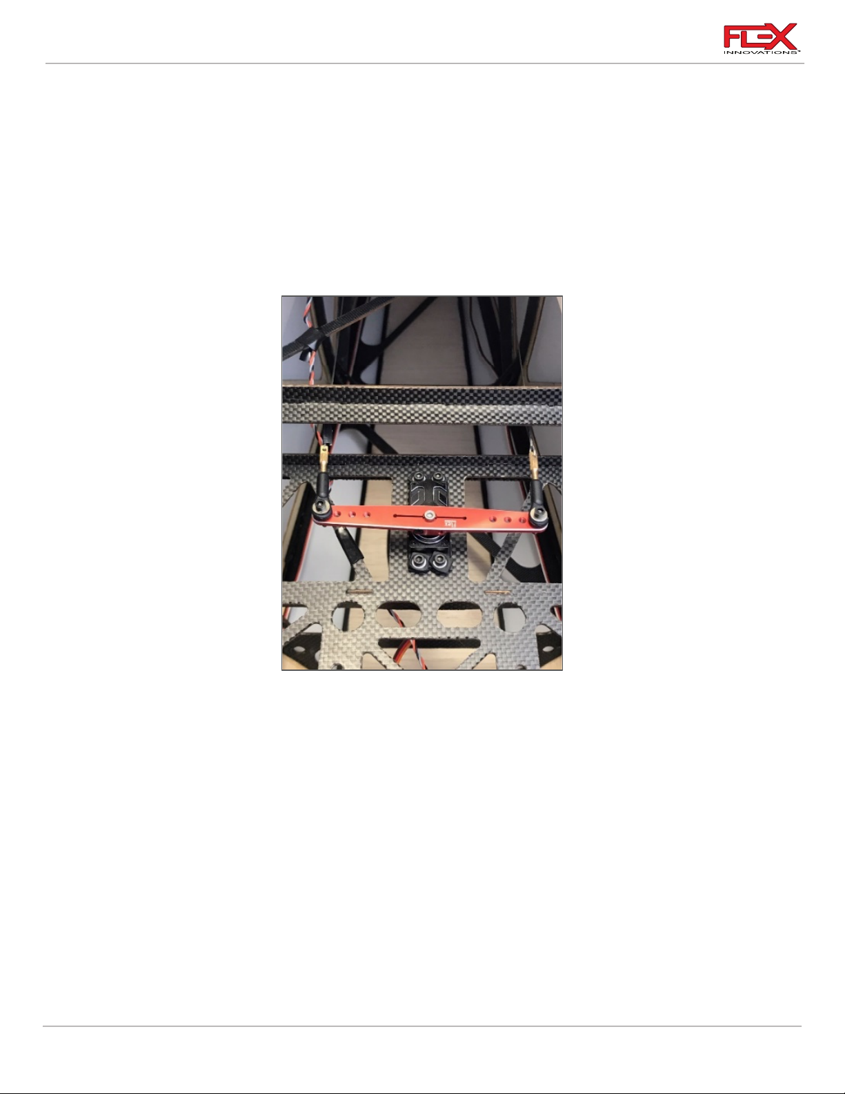
6. Thread a rigging coupler approximately one-third of the way into your final two ball links.
Secure the ball link and rigging coupler assembly to each side of the rudder servo arm.
The order of hardware is as follows:
o M3x15 Socket Head Cap Screw
o M3 Washer
o Ball Link (with rigging coupler)
o Servo Arm
o M3 Washer
o M3 Lock Nut
7. Route the pull-pull wire through the fuselage and out the exit holes. Be sure to route the
cables so that they do not tangle or cross. The cables should route straight from the servo
arm to the exit of the fuselage.
8. Attach the ball link to the rudder control horn using a 2.5mm hex driver and a 5.5mm nut
driver. Use the same order of hardware as done with the aileron control horns.
9. Power on your radio system and make sure the control horn is perpendicular to the servo
case. Route a cable through a piece of heat shrink tubing, through a crimp and then
through the rigging coupler mounted to the servo arm. Route the cable back through the
crimp. For extra security, you can loop the cable around the crimp a final time. Repeat for
the other pull-pull cable.
10. Pull the cables tight, while keeping the rudder centered. Once happy with the centering
of the servo with the cables tight, use a crimping tool to permanently attach the crimp to
the cables. Apply a small amount of thin CA to the cable and crimp joint for extra security.
Once the CA has fully cured, slide the heat shrink over the joint and shrink it to secure it in
place.
31
Page 36
RV-8 70cc FLS Instructions
!
Required for this section
Components
Tools
Adhesives/Building Materials
o 2-inch Single-Sided
Servo Arm
o Ball Link (2)
o M3x15 Socket Head Cap
Screw (2)
o M3 Flat Washer (4)
o M3 Lock Nut (2)
o 48-inch (1220mm) Servo
Extension
o 4-3/4-inch (120mm)
Linkage
o Hobby Knife with a #11
blade
o #1 Phillips Screwdriver
o Thin CA
!
11. Adjust final cable tension by removing the ball links and by threading the rigging coupler
further into the ball link. Start with the side that was only threaded one-third of the way
into the link. Be sure to keep the rudder centered in the process. Do not over tighten the
cables.
Quique’s Tip:
When new, pull-pull cables will stretch slightly in the first several flights. Adjust the tension as
needed until the stretching stabilizes.
Push/Pull System, Servo Installed in Fuselage
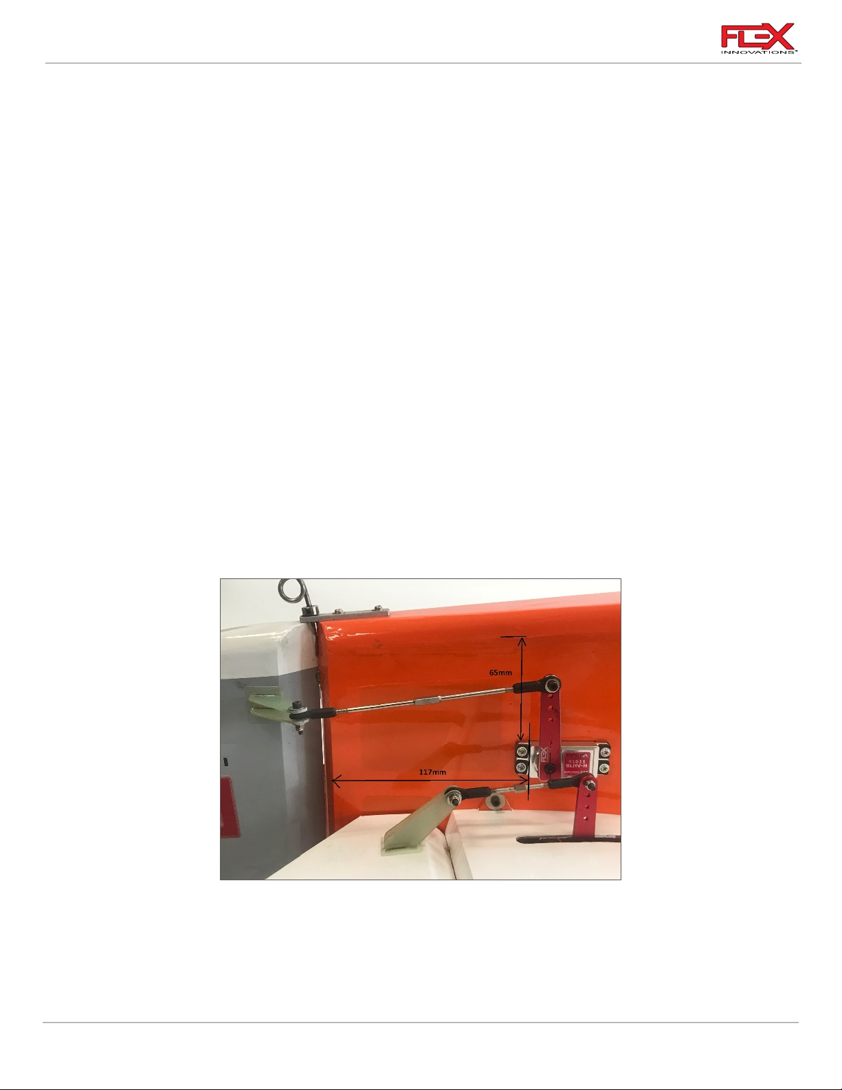
1. Locate the rudder servo bays in the rear of the fuselage. They are located approximately
65mm from the bottom of the fuselage, and 117mm from the start of the rudder hinge
bevel. Choose which side you wish to mount the servo to and use a hobby knife with a
fresh #11 blade to remove the covering, leaving approximately 1/8-inch (3mm) extra
covering over the inside of the pocket. Use a covering or trim iron to seal the covering
into the slot.
32
Page 37
RV-8 70cc FLS Instructions
!
!
!
!
!
!
2. Use a #1 Phillips screwdriver to thread a servo mounting screw into each of the pre-cut
holes in the servo mounting rails. Remove the screw and apply a small amount of thin CA
to each of the holes to harden the threads cut by the screw. Let the CA fully cure before
proceeding.
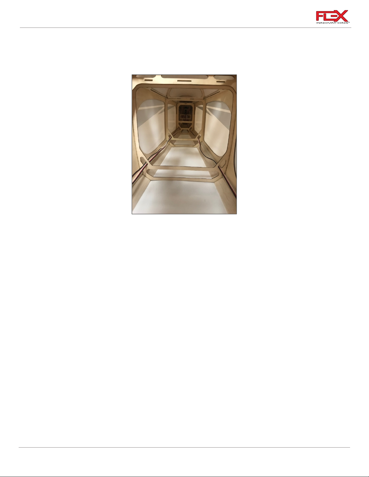
3. Attach a 48-inch (1220mm) servo extension to the servo. Use a Servo Connector Safety
Clip (FPZA1040), thread or heat shrink tubing to secure the extension in place. Route the
servo extension through the holes in the formers as shown in the picture above.
4. Install the servo into the pocket with the output shaft toward the rear of the airplane.
5. Power on your radio system to center the servo. Install a 2-inch (51mm) servo arm onto
the servo. Apply a small amount of blue thread lock to the servo arm screw and secure it
in place. If your servo arm has clamping screws, apply blue thread lock to these screws
and secure them in place. Note that you may need to power off the model and rotate the
servo arm by hand to have access to each screw.
6. Using a pushrod 4-3/4-inches (120mm) long, assemble the rudder linkage so that the
total length from center of ball to center of ball is approximately 5.7-inches (145mm).
Final length will be adjusted once the linkage has been attached to the servo and control
horn.
7. Attach the linkage to the servo arm. The correct hole location is 2-inches (51mm) from
the center of the servo arm. If you are using the recommended servo arm, this is the
outermost hole. The order of hardware components, starting from the top of the servo is
as follows:
o M3x15 socket head cap screw
o M3 washer
o Ball Linkage
o Servo Arm
o M3 washer
o M3 locknut
33
Page 38
RV-8 70cc FLS Instructions
!
!
Required for this section
Components
Tools
Adhesives/Building Materials
o Carbon Fiber Horizontal
Stabilizer Tube
o Left and Right Horizontal
Stabilizers
o M3x15 Socket Head Cap
Screw (4)
o M3 Washer (4)
o 48-inch (1220mm)
elevator extensions (2)
o Hobby Knife with a #11
blade
o #1 Phillips Screwdriver
o 2.5mm Hex Driver
o Thin CA
o Blue Thread Lock
!
8. Attach the linkage to the control horn. The order of hardware components, starting from
the tip of the rudder is as follows:
o M3x15 socket head cap screw
o M3 washer
o Control Horn #1
o Ball Linkage
o Control Horn #2
o M3 washer
o M3 locknut
9. With the radio powered on, make any final adjustments to the linkage length to center
the rudder accordingly.
MOUNTING THE STAB
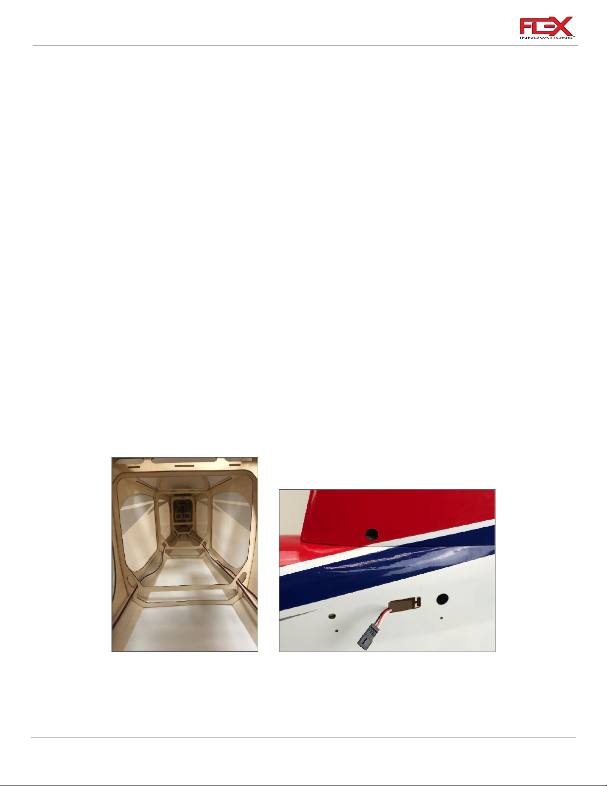
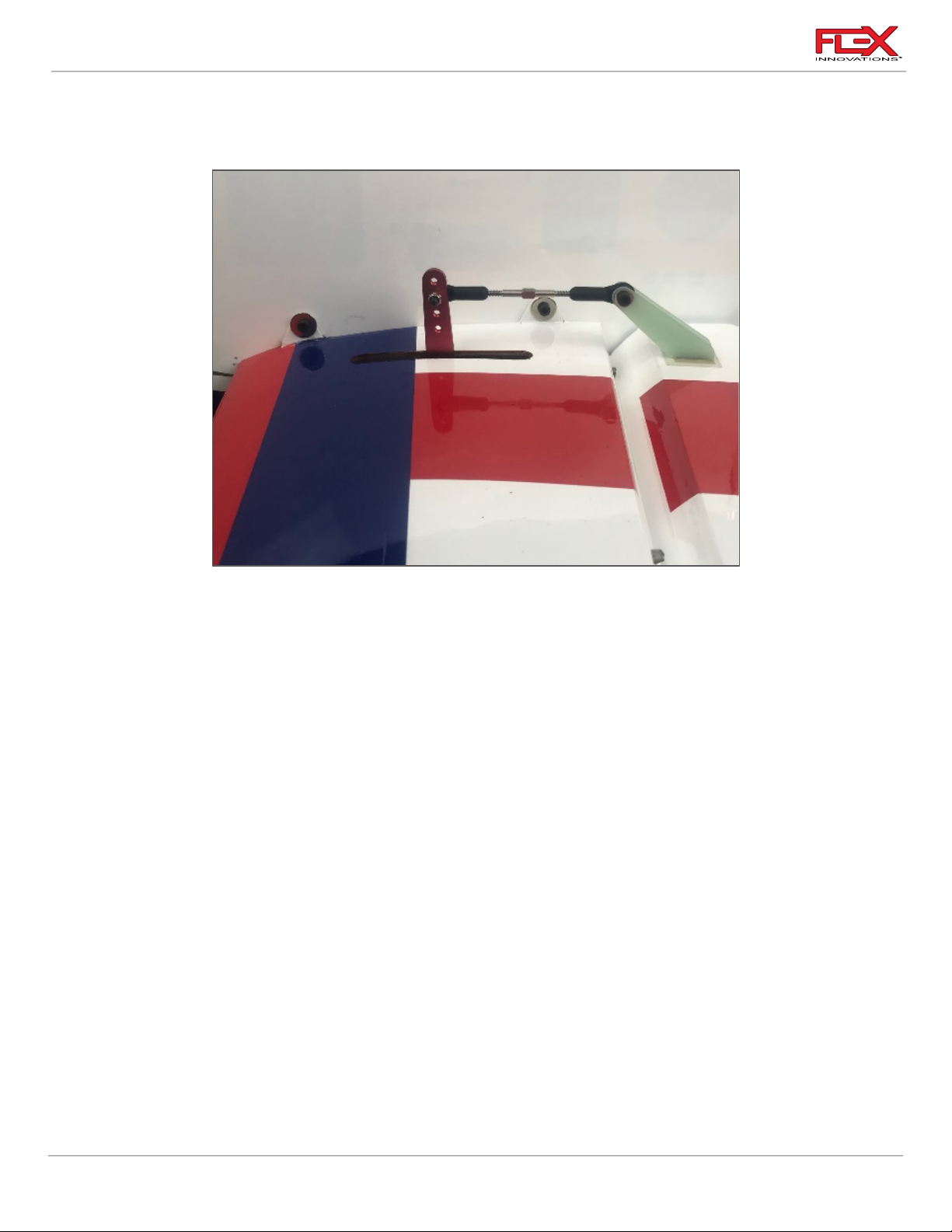
1. Route the (2) 48-inch (1220mm) elevator servo extensions through the holes in the
corners of the formers to keep them from bouncing around inside the fuselage. Place the
female end of the servo extension in the retention slot cutout at the exit of the fuselage.
This will prevent the extension from falling back into the fuselage.
34
Page 39
RV-8 70cc FLS Instructions
!
!
!
Required for this section
Components
Tools
Adhesives/Building Materials
o Fuselage Assembly
o Wheel Pant (2, L & R)
o Main Wheel (2)
o M4x25 Socket Head Cap
Screw (4)
o M4 Flat Washer (2)
o M4 Lock Nut (6)
o M3x15 Socket Head Cap
Screw (4)
o M3 Flat Washer (4)
o Landing Gear Axle (2)
o M5 Lock Collar (4)
o 1.5mm Hex Driver
o 2.5mm Hex Driver
o 3mm Hex Driver
o Small Flat File
o 7mm Wrench
o 10mm Wrench
o 13mm Wrench
o Needle Nose Pliers
(optional)
o Blue Thread Lock
2. Insert the carbon fiber horizontal stab tube into the appropriate hole in the fuselage and
approximately center it left and right. Slide the left horizontal stabilizer onto the carbon
tube and route the servo extensions further through the fuselage.
3. Use a 2.5mm hex driver to secure (2) M3x15 socket head cap screws and (2) M3x12 flat
washers in place.
4. Repeat steps 2 and 3 for the right horizontal stabilizer.
LANDING GEAR INSTALLATION
35
Page 40

RV-8 70cc FLS Instructions
!
!
1. Assemble the axle to the landing gear leg. Use one 5mm flat washer between the lock
nut and the landing gear leg as shown above. Fully tighten using a 10mm and 13mm
open end wrench.
2. Temporarily slide a lock collar fully onto the axle, and space it 2mm (3/32-inch) off the
axle flange. Secure it in place with a 1.5mm hex driver. Slide a wheel onto the axle,
followed by a second wheel collar, securing it in place by a 1.5mm hex driver. Use a felttipped pen to place a mark on the inside edge of the inner lock collar and the outside
edge of the outer lock collar. Remove both lock collars and the wheel from the axle.
36
Page 41

RV-8 70cc FLS Instructions
!
!
!
3. Use a flat file to make two flat spots on the axle for the wheel collar set screws to tighten
against, noting the marks from the previous step. Keep in mind that the marks made
were on the outside edge of the collar, not the center so you will need to offset your file
from these marks. Do not remove a lot of material as it will weaken the axle. You only
need a small flat spot for each set screw.
4. Re-assemble the lock collars and wheel as done in step one. Use blue thread lock on the
set screw and tighten the lock collar down. Be sure to orient the collars so that the side
with the smallest diameter faces the wheel. Ensure that the wheel spins freely after
everything has been tightened.
5. Install the wheel pants using a 2.5mm hex driver, two M3x15 socket head cap screws and
two M3 washers. Apply blue thread lock to the screws before securing them in place.
37
Page 42
RV-8 70cc FLS Instructions
!
!
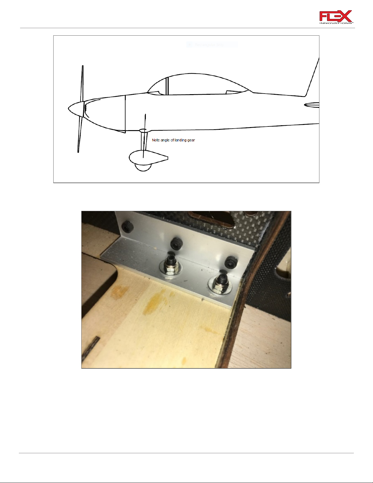
6. Be sure to note that the landing gear sweeps forward as it moves away from the fuselage.
The wheel pant mounting holes are specific to a side.
7. With the fuselage inverted on your workspace, place the landing gear on the fuselage so
that it sweeps forward as it moves away from the fuselage. Place an M4x25 socket head
cap screw with an M4 washer through the landing gear and through the landing gear
mount in the fuselage. Note that there are not threads in the aluminum angle mount in
the fuselage. Place an M4 washer over the screw, followed by an M4 lock nut. You may
need to use needle nose pliers to access the screws more easily from inside the fuselage.
Tighten the screws using a 3mm hex driver and an 7mm open end wrench. Do not fully
tighten until all four M4 screws are in place, and the M4 lock nuts have been started.
38
Page 43
RV-8 70cc FLS Instructions
Required for this section
Components
Tools
Adhesives/Building Materials
o Fuselage Assembly
o Engine
o Engine Standoffs (20mm)
o ¼-20 Blind Nut (4)
o ¼-20 x 1-1/2-inch Socket
Head Screw (4)
o ¼-inch flat washer (4)
o Drill
o 1/8-inch (3mm) Drill Bit
o 5/16-inch (8mm) Drill Bit
o ¼-inch Hex Driver
o Blue Thread Lock
!
ENGINE AND THROTTLE SERVO INSTALLATION
The RV-8 70cc FLS is designed for 50-60cc single cylinder engines, or twin 70-76cc engines.
This manual will cover the installation of the DA-70 and the DA-60.
DA-70 ENGINE INSTALLATION
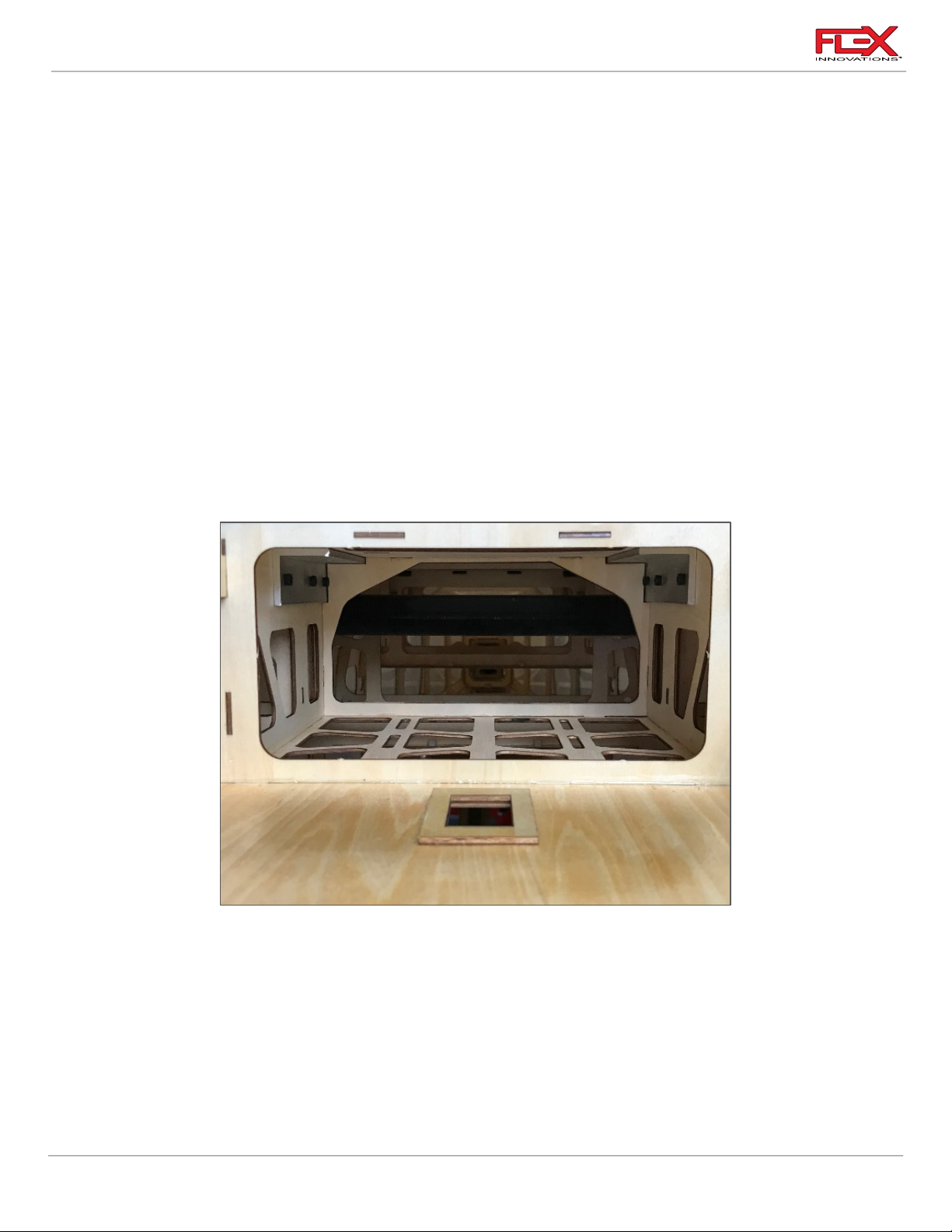
1. Remove the plywood structure on the fuselage, just below the motor box and behind the
throttle servo mounting location by pushing with your fingers. If this does not push out
easily, you can trace the shape with a sharp #11 hobby knife to make it easier to remove.
Regardless of the exhaust system used, this must be removed for proper cooling.
39
Page 44
RV-8 70cc FLS Instructions
!
!
!
!
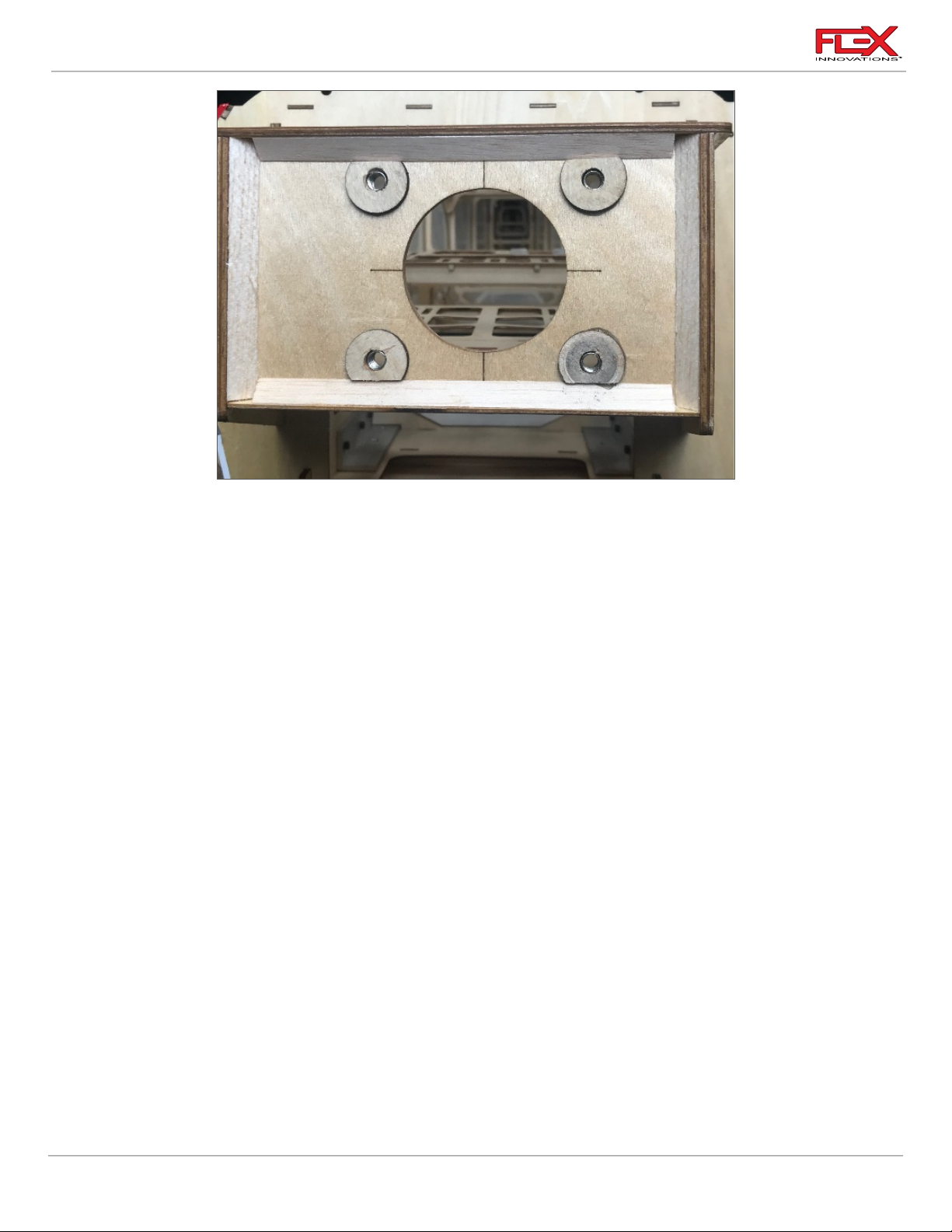
2. The engine mounting locations for the DA-70 is laser-etched into the firewall for your
convenience. If using a different mounting pattern, the “+” represents the engine
crankshaft. Use a 1/8-inch drill bit and drill to create a pilot hole in the center of the four
bolt hole etchings in the firewall. Use a 5/16-inch drill bit to enlarge these holes. Verify
that the hole is large enough to accommodate the blind nuts which will be installed in
the step 4.
3. Using CA, install the (4) 3mm plywood washers.
4. Use a ¼-20 x 1-1/2-inch screw, ¼-inch flat washer, and 20mm standoff to pull the blind
nut into the back side of the firewall. Once fully seated, you may apply some medium CA
to help secure the blind nut. Ensure that you don’t get any adhesive on the threads of the
blind nut. Let the CA fully cure before moving to the next step.
5. Mount the engine (without the exhaust) to the firewall using (4) 20mm engine standoffs,
(4) ¼-20 x 1-1/2-inch socket head cap screws and (4) ¼-inch flat washers. Be sure to apply
blue thread lock to the motor mount screws. The order of components is as follows:
o ¼-20 x 1-1/2-inch Socket Head Cap Screw
o ¼-inch flat washer
o Engine
o 20mm Engine Standoffs
o Firewall
o ¼-20 Blind Nut
40
Page 45

RV-8 70cc FLS Instructions
Required for this section
Components
Tools
Adhesives/Building Materials
o Fuselage Assembly
o Throttle Servo
o 18-inch (460mm) Servo
Extension
o Safety Servo Clip
Connector
o 2mm White Ball Link
o M2x10 Phillips Head
Screw (1)
o M2 Flat Washer (2)
o M2 Lock Nut (1)
o #1 Phillips Screwdriver
o 2.5mm Hex Driver
o Thin CA
o Blue Thread Lock
!
!
DA-70 Throttle Servo and Throttle Linkage Installation
1. Attach the 18-inch (460mm) servo extension to the throttle servo. Use a Servo Connector
Safety Clip (FPZA1040), thread or heat shrink tubing to secure the extension in place.
2. There are two options for the servo tray. The middle location is normally used when stock
mufflers are used. The one to the side of the motor box is used when canisters are used.
41
Install the throttle servo with the output shaft towards the nose of the aircraft.
Page 46
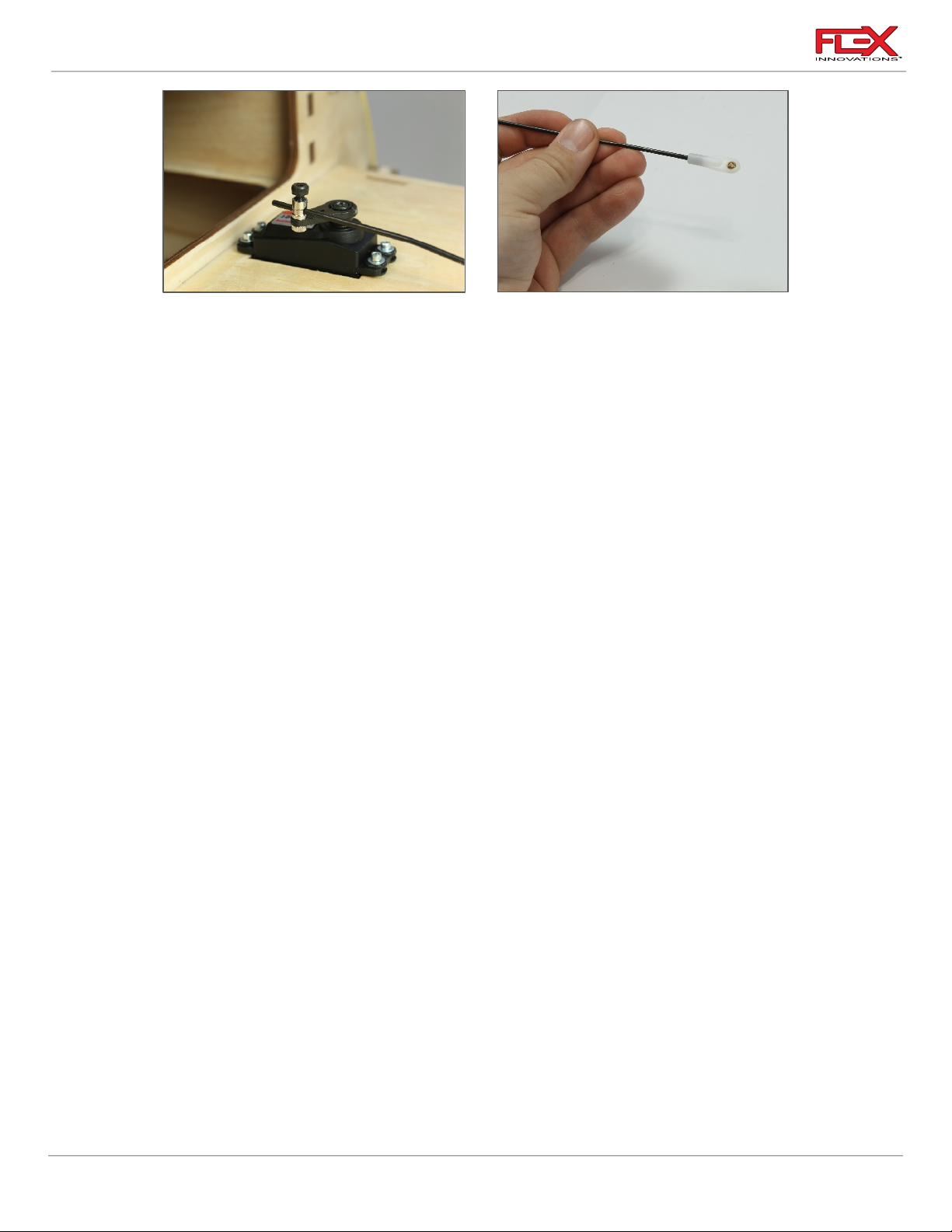
RV-8 70cc FLS Instructions
!
!
!
!
3. Use the radio system to center the servo, then install a 1-inch (25mm) servo arm onto the
servo. If you used the middle location, make sure the servo arm is oriented to the side of
the fuselage that provides the straightest geometry to the throttle arm on the engine. If a
canister is used, orient the servo arm towards the centerline of the fuselage to provides
the straightest geometry to the throttle arm on the engine. Do not secure the servo arm
screw currently.
4. Secure the quick connector to your servo arm. Be sure to use blue thread lock for a secure
attachment. The order of components is as follows:
o Quick connect housing
o Washer
o Servo Arm
o Washer
o Nut
5. Locate the pushrod that is only threaded at one end. Thread this linkage approximately
halfway into a WHITE ball linkage. Secure the ball link to your engine throttle arm using
the 2 x 10mm screw, 2mm washers (2), and 2mm lock nut. Do not use thread lock on
these parts, as it can weaken the plastic insert in the lock nut. The order of these
components should be:
o Screw
o Washer
o Throttle Arm
o Washer
o Lock Nut.
6. Remove the M3x5 socket head cap screw from the quick connect. Insert the nonthreaded portion of the throttle linkage through the hole in the side of the quick connect.
With the radio powered on, center the throttle servo and engine throttle arm. Use blue
thread lock and secure the M3x6 screw onto the linkage. Check throttle movement and
position relative to stick position and make any changes necessary. Fully tighten the
screw.
Quique’s Tips:
o Use the shortest servo arm possible while still getting full throttle arm movement on your
engine. Your throttle end points should be around 110-120% when finished with the
installation. A faster servo (like the Potenza DS22209HV) with a shorter arm is preferred over a
slower servo with a longer arm.
42
Page 47
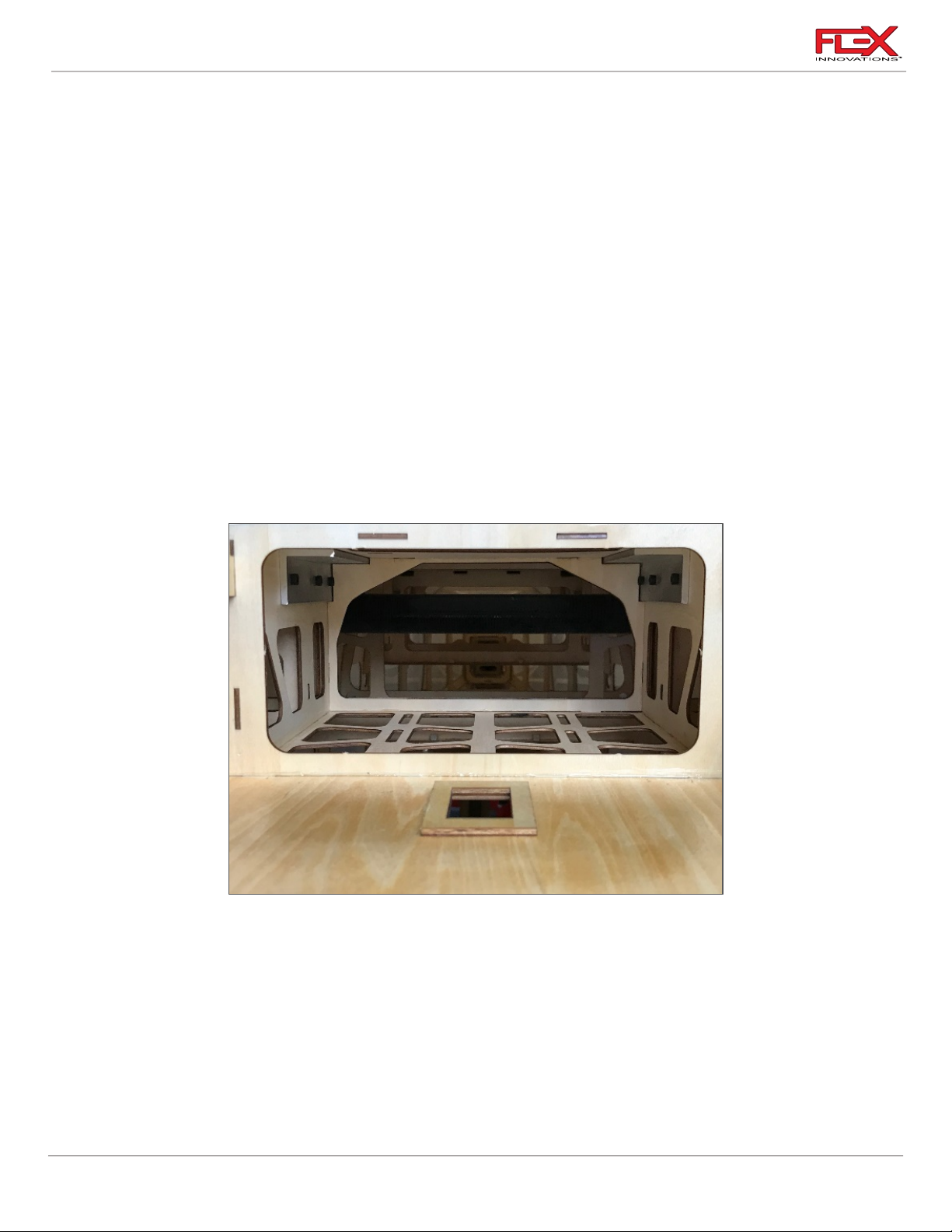
RV-8 70cc FLS Instructions
Required for this section
Components
Tools
Adhesives/Building Materials
o Fuselage Assembly
o Engine
o Engine Standoffs (30mm)
o ¼-20 Blind Nut (4)
o ¼-20 x 1-1/2-inch Socket
Head Screw (4)
o ¼-inch flat washer (4)
o Drill
o 1/8-inch (3mm) Drill Bit
o 5/16-inch (8mm) Drill Bit
o ¼-inch Hex Driver
o Blue Thread Lock
!
!
Quique’s Tips (continued):
o For the most linear throttle response, adjust the throttle linkage length to balance the end
points for your throttle servo. You do NOT want your end points to be mismatched (example:
60/120). Get your end points as close to one another as possible (example: 114/116) for the
most linear throttle response.
DA-60 ENGINE INSTALLATION
1. Remove the plywood structure on the fuselage, just below the motor box and behind the
throttle servo mounting location by pushing with your fingers. If this does not push out
easily, you can trace the shape with a sharp #11 hobby knife to make it easier to remove.
Regardless of the exhaust system used, this must be removed for proper cooling.
2. The engine mounting locations for the DA-60 is laser-etched into the firewall for your
convenience. If using a different mounting pattern, the “+” represents the engine
crankshaft. Use a 1/8-inch drill bit and drill to create a pilot hole in the center of the four
43
bolt hole etchings in the firewall. Use a 5/16-inch drill bit to enlarge these holes. Verify
that the hole is large enough to accommodate the blind nuts which will be installed in
the next step.
Page 48

RV-8 70cc FLS Instructions
!
!
3. Use a ¼-20 x 1-1/2-inch screw, ¼-inch flat washer, and 30mm standoff to pull the blind
nut into the back side of the firewall. Once fully seated into the firewall, you may apply
some medium CA to help secure the blind nut. Ensure that you don’t get any adhesive on
the threads of the blind nut. Let the CA fully cure before moving to the next step.
4. Mount the engine (without the exhaust) to the firewall using (4) 30mm engine standoffs,
(4) ¼-20 x 1-1/2-inch socket head cap screws and (4) ¼-inch flat washers. Be sure to apply
blue thread lock to the motor mount screws. The order of components is as follows:
o ¼-20 x 1-1/2-inch Socket Head Cap Screw
o ¼-inch flat washer
o Engine
o 30mm Engine Standoffs
o Firewall
o ¼-20 Blind Nut
44
Page 49
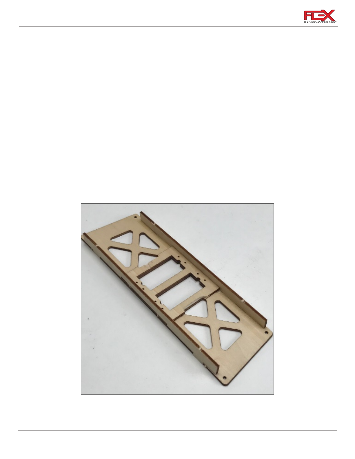
RV-8 70cc FLS Instructions
Required for this section
Components
Tools
Adhesives/Building Materials
o Fuselage Assembly
o Throttle Tray
o Throttle Servo
o choke servo (optional)
o 18-inch (460mm) Servo
Extension
o 2mm White Ball Link
o M2x10 Phillips Head
Screw (1)
o Safety Servo Clip
Connector
o M2 Flat Washer (2)
o M2 Lock Nut (1)
o 2mm wood servo screw
(4)
o #1 Phillips Screwdriver
o 2.5mm Hex driver
o Blue Thread Lock
o Epoxy or CA
!
Throttle Installation
1. Using CA or epoxy, build the DA-60 servo tray as shown in the picture above.
45
Page 50
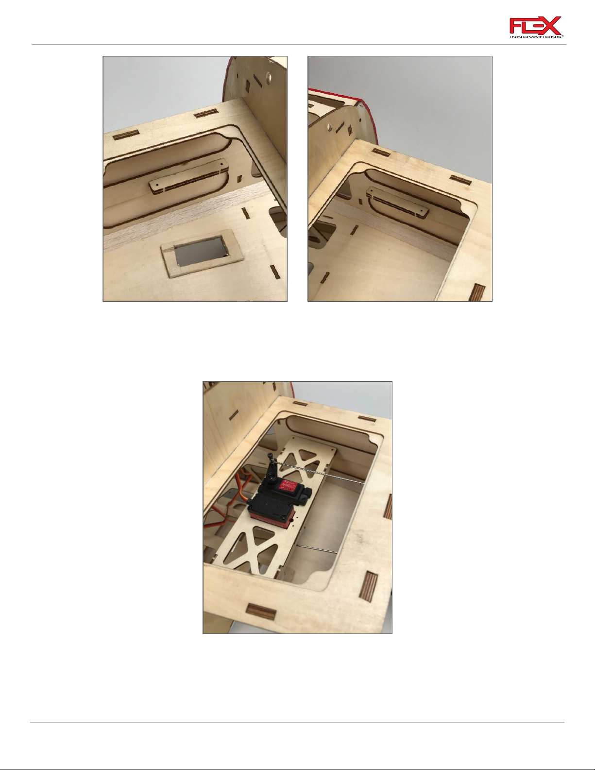
RV-8 70cc FLS Instructions
!
!
!
2. Using CA, take two mounting rails and glue them together to double their thickness.
Once dry, use 30-minute epoxy to glue each set of rails to the sides of the motor box.
3. Attach the 18-inch (460mm) servo extension to the throttle servo. Use a Servo Connector
Safety Clip (FPZA1040), thread or heat shrink tubing to secure the extension in place.
4. When viewing the aircraft as if you were the pilot, install the servo right side up on the
left side of the tray as shown in the picture. Optionally, you can mount the choke servo
upside down and on the right side of the tray. NOTE: The throttle and choke servo can be
mounted in any orientation desired. It is preferred, however, to mount the servo with the
output shaft toward the nose of the aircraft.
46
Page 51

RV-8 70cc FLS Instructions
!
!
!
!
!
5. Secure the tray in place using (4) M2.5x8 self-tapping screws and a #1 Phillips screwdriver
in the location shown in the picture in Step 4.
6. Use the radio system to center the servo, then install a 1-inch (25mm) servo arm onto the
servo. Make sure the servo arm is oriented to the side of the fuselage that provides the
straightest geometry to the throttle arm on the engine. Do not secure the servo arm
screw currently.
7. Secure the quick connector to your servo arm. Be sure to use blue thread lock for a secure
attachment. The order of components is as follows:
o Quick connect housing
o Washer
o Servo Arm
o Washer
o Nut
8. Locate the pushrod that is only threaded at one end. Thread this linkage approximately
halfway into a WHITE ball linkage. Secure the ball link to your engine throttle arm using
the 2 x 10mm screw, 2mm washers (2), and 2mm lock nut. Do not use thread lock on
these parts, as it can weaken the plastic insert in the lock nut. The order of these
components should be:
o Screw
o Washer
o Throttle Arm
o Washer
o Lock Nut.
9. Remove the M3x5 socket head cap screw from the quick connect. Insert the nonthreaded portion of the throttle linkage through the hole in the side of the quick connect.
With the radio powered on, center the throttle servo and engine throttle arm. Use blue
thread lock and secure the M3x6 screw onto the linkage. Check throttle position relative
to stick position and make any changes necessary. Fully tighten the screw.
Quique’s Tips:
o Use the shortest servo arm possible while still getting full throttle arm movement on your
engine. Your throttle end points should be around 110-120% when finished with the
installation. A faster servo (like the Potenza DS22209HV) with a shorter arm is preferred over a
slower servo with a longer arm.
47
Page 52
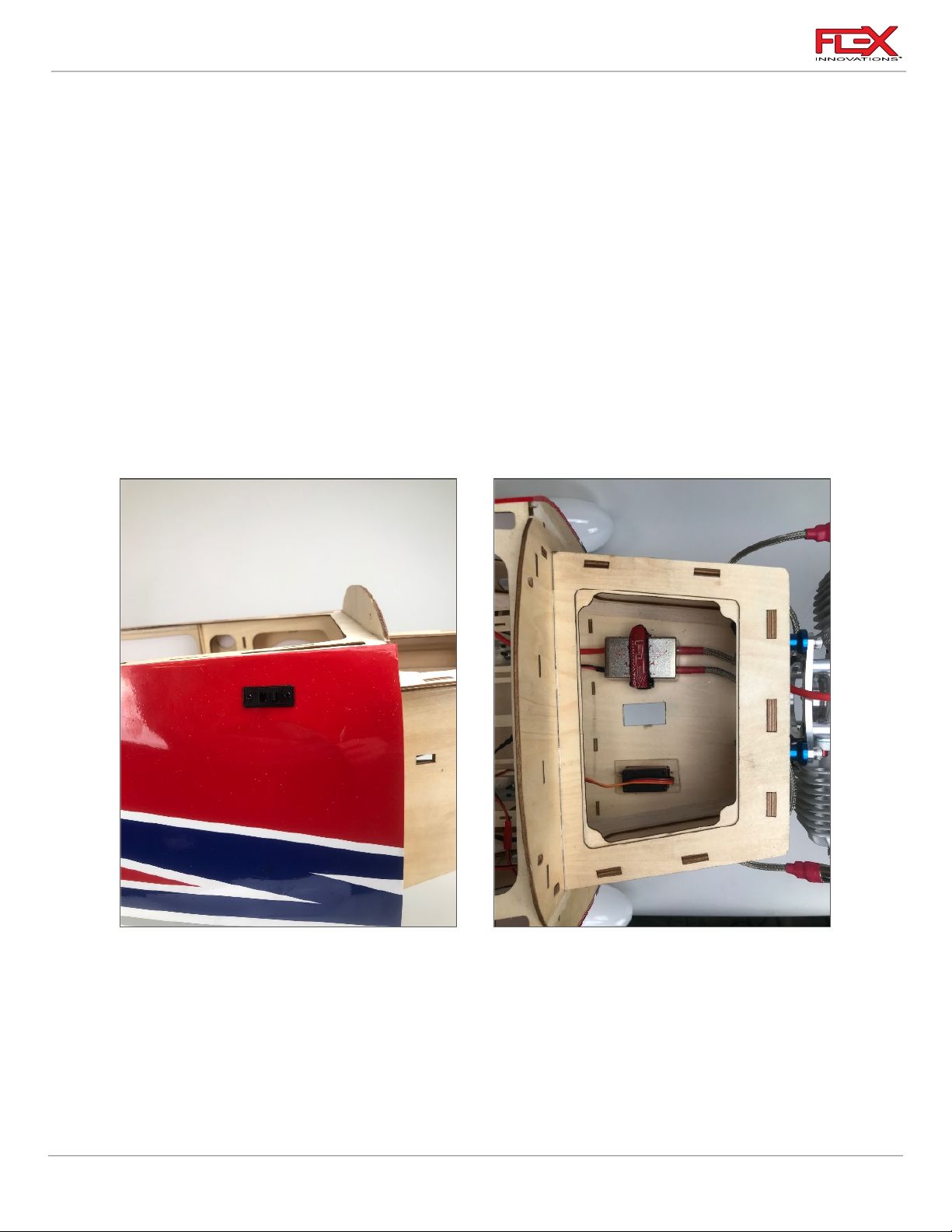
RV-8 70cc FLS Instructions
Required for this section
Components
Tools
Adhesives/Building Materials
o Fuselage Assembly
o Ignition
o Ignition Switch
o Ignition Battery
o Regulator (if applicable)
o Hobby Knife w/#11 Blade
o Hook and Loop Strap (2)
o Adhesive-Back Hook and
Loop Tape
!
Quique’s Tips (continued):
o For the most linear throttle response, adjust the throttle linkage length to balance the end
points for your throttle servo. You do NOT want your end points to be mismatched (example:
60/120). Get your end points as close to one another as possible (example: 114/116) for the
most linear throttle response.
IGNITION INSTALLATION
1. Locate the ignition switch hole towards the nose of the fuselage. Note that there are
switch locations on both sides of the fuselage for your preference. Use a hobby knife with
a #11 blade to remove the covering from the hole of your choice. Test fit your switch and
modify the hole if needed. Secure it in place using the screws included with your switch.
If your switch mounting screws thread into metal, be sure to apply blue thread lock. DO
NOT apply blue thread lock if they thread into plastic.
48
Page 53
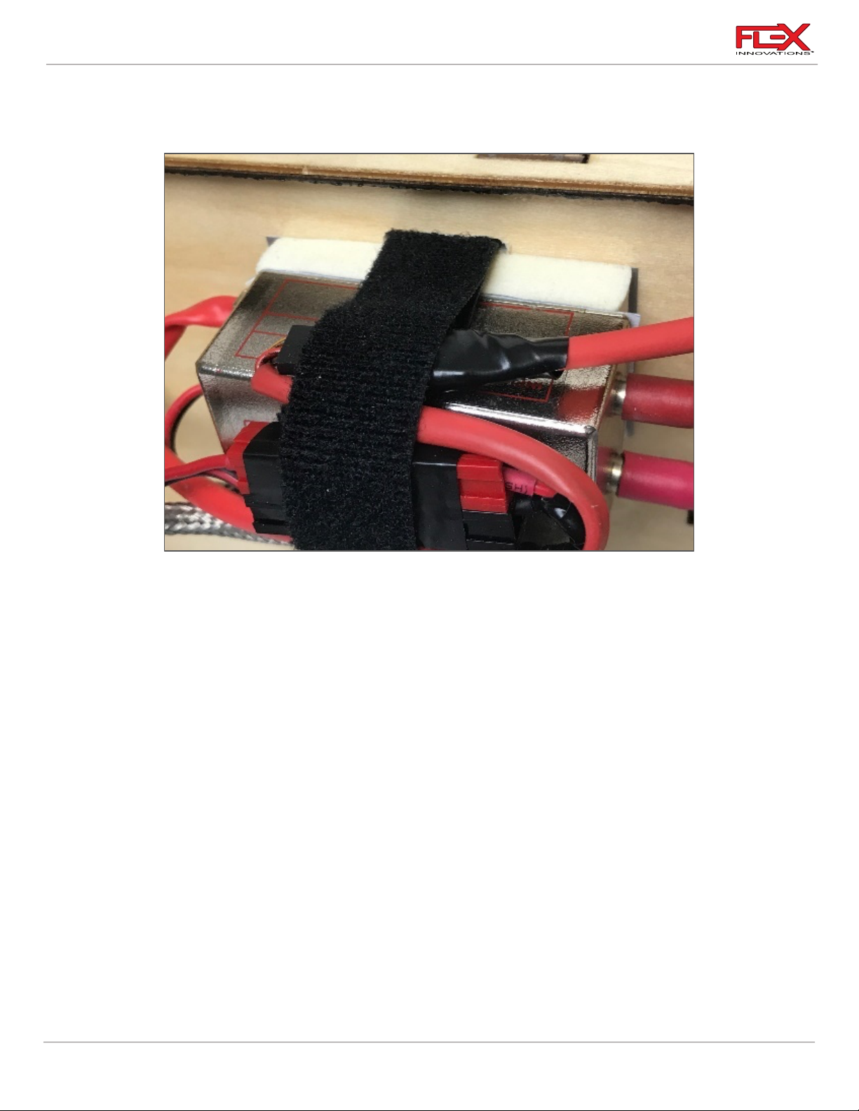
RV-8 70cc FLS Instructions
!
!
2. The ignition can be mounted wherever you prefer. We have found that with the DA60/70 the above depicted location works well. There are many ways to install an ignition
and we recommend you mount it per your engine manufacturer’s instructions.
3. Once you’ve decided where to mount the ignition, you need to make 2 slots for the hook
and loop straps to pass through the motor box. Use a felt-tipped pen to mark each side of
the ignition you want the strap to pass through. Use a rotary tool with a cutoff wheel (or
rotary bit of your choice) to make the slots in the motor box. Keep these slots as small as
possible to prevent weakening the motor box.
Quique’s Tip:
o Over the years, I have found that the below described system provides a solid mounting
platform, while still providing enough dampening from vibration. Mount as you prefer, but
this works very well and is a proven method for a long-lasting mounting solution:
o Cut a piece of ¼-inch (6mm) thick, soft foam the same size as the ignition box. Apply
adhesive-backed hook and loop tape on the ignition and both sides of the foam rectangle.
Stick the foam to the ignition. Apply another piece of adhesive-backed hook and loop tape to
the motor box where you will mount the ignition. Make sure it is the opposite type when
compared to the hook and loop on the ¼-inch foam. Stick the ignition and foam assembly to
the motor box and strap it to the motor box using hook and loop strap. Tighten the strap
around the ignition so that it is firm and relatively tight. Don’t over-tighten as you do want
some vibration dampening effect from the foam.
49
Page 54

RV-8 70cc FLS Instructions
!
!
Required for this section
Components
Tools
Adhesives/Building Materials
o Fuselage Assembly
o Fuel Tank
o Fuel Line
o Pliers
o Hook and Loop Strap (2)
o Adhesive-Back Hook and
Loop Tape
4. Place your ignition battery inside the fuselage as shown in the above picture. Use
adhesive-backed hook and loop tape between the battery and the fuselage and secure
the battery with a hook and loop strap.
5. Route all your wiring and make all electronic connections at this time. Secure any
permanent connections with Servo Safety Clips (FPZA1040). Be sure to secure the wiring
so that it will not bounce around in the aircraft. Also, be sure to secure the wiring in a way
the wires will not chafe over time from vibration. A typical ignition setup will be
connected as follows:
Ignition Battery ➞ Ignition Switch ➞ Ignition Regulator ➞ Ignition ➞ Engine
FUEL TANK INSTALLATION
The Flex Innovations Lightweight 24oz Fuel Tank is included with your RV-8 70cc FLS. Before
installing the fuel tank check all fittings are properly installed and that the clunk line inside the tank is
appropriately sized.
50
Page 55
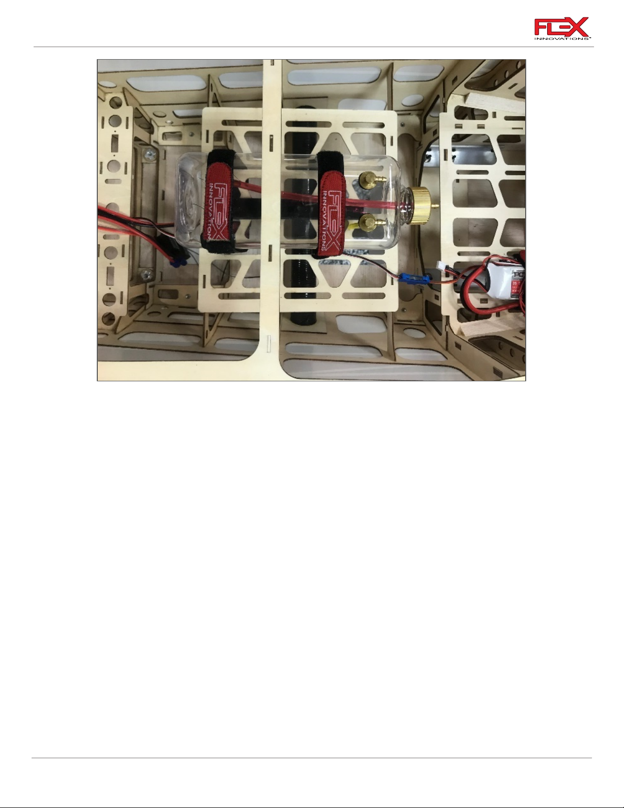
RV-8 70cc FLS Instructions
!
1. The fuel tank tray has plenty of room for your fuel tank. If you are using a single tank, you
can place the fuel tank in the middle of the tray as shown in the image above. the image
above shows the optional 32oz Lightweight Fuel/Smoke tank (FPM1623). If you plan on
using a smoke system, two of the 24oz Lightweight Fuel/Smoke tanks (FPM2019) should
be used. One is included in your kit.
Apply adhesive-backed hook and loop tape to the bottom of your tank(s) and to the fuel
tank tray. Place the tank(s) in their location and secure them with two hook and loop
straps. These straps should be snug but not overly tight, as the fuel tanks are very
lightweight and can be easily crushed. The hook and loop tape on the bottom of the
tank(s) will prevent the tank from moving fore and aft, and the hook and loop straps will
prevent the tank from pulling away from the tray.
51
Page 56
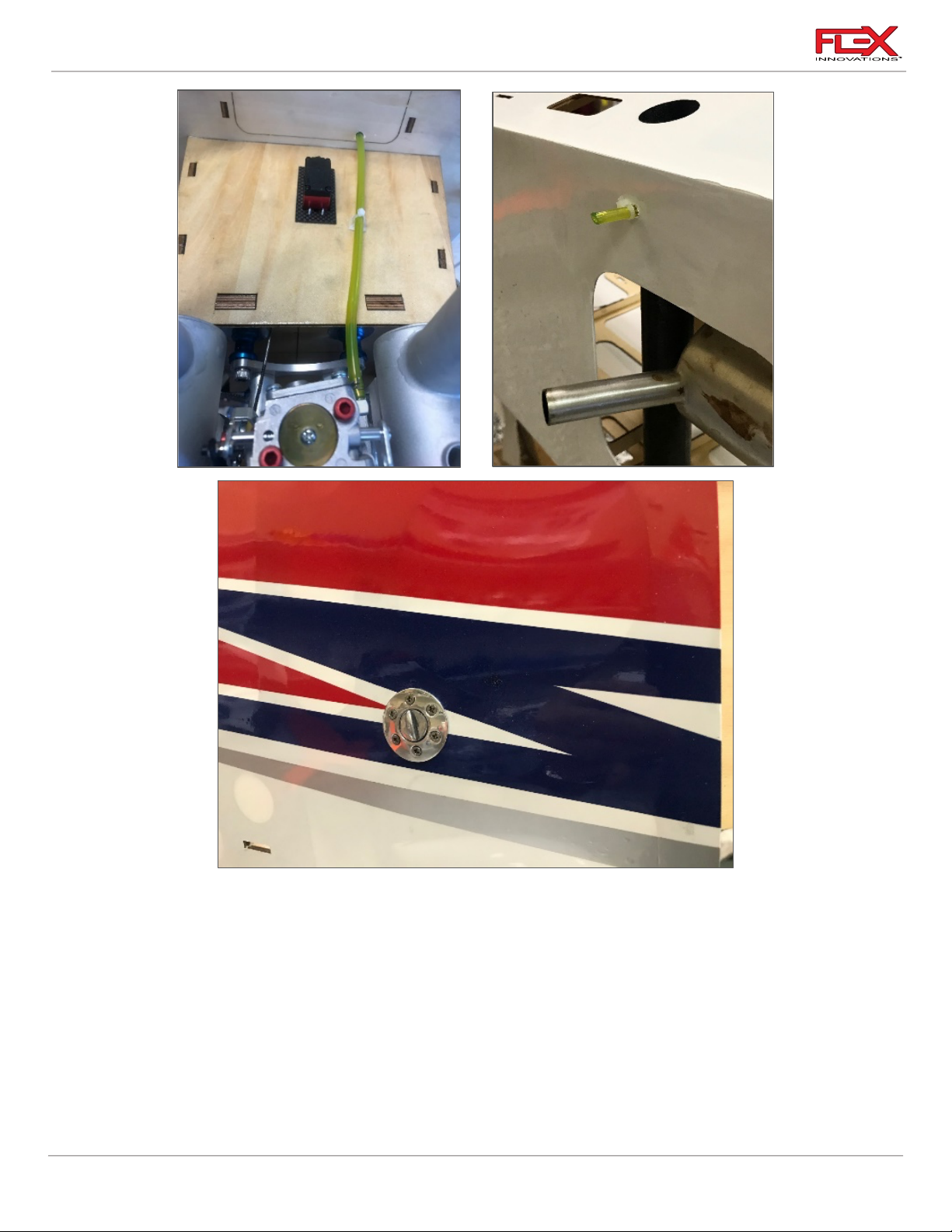
RV-8 70cc FLS Instructions
!
2. After the tank is in position, route and trim your fuel lines appropriately. Your clunk line
should go to the carburetor or throttle body. The fill line should go to your fuel dot or
filling system. We recommend the McFueler Fuel Dot (FPMAMCFUELER). The vent line
should wrap around the back of the tank(s) and pass back in front of the tank(s). It should
then exit the bottom of the fuselage as shown in the image above. After the vent line
exits the fuselage, use a cable tie around the fuel line to prevent it from slipping back into
the fuselage. Don’t over-tighten the cable tie, as air and fuel will need to vent from this
line. Be sure to keep your fuel line away from components that get hot (like your exhaust
or cylinder heads) and route it in such a way that it will not bounce around or chafe on
any of the interior structure of the fuselage.
52
Page 57

RV-8 70cc FLS Instructions
Required for this section
Components
Tools
Adhesives/Building Materials
o Fuselage Assembly
o Cowling
o Cowling Baffles
o Muffler (or
Canisters/Headers)
o Exhaust Gasket (2)
o M3 x 15 Socket Head Cap
Screw (4)
o M3 Flat Washer (4)
o M2.5 x 8 Wood Screw
o Motor Box Cover Plate
o 2.5mm Hex Driver
o #1 Phillips Screwdriver
o Rotary Tool
o Rotary Tool Sanding
Drum
o Felt-Tipped Pen
o Colored Silicone (Red
typically preferred)
o Thin CA
o Medium CA
o CA Accelerator
!
EXHAUST AND COWLING INSTALLATION
If you plan to use stock mufflers, please follow the instructions (A) below. If you plan on using
canisters, please follow canister instructions (B) on the following pages. Be sure to follow the engine
baffling instructions for both setups.
Muffler Installation (A)
1. Install the muffler on the engine using the hardware provided with your engine. Follow
your engine manufacturer’s installation instructions. Typically, most engines will use a
gasket between the muffler and cylinder and the socket head cap screws will pass
through a lock washer before securing the muffler to the cylinder.
53
Page 58
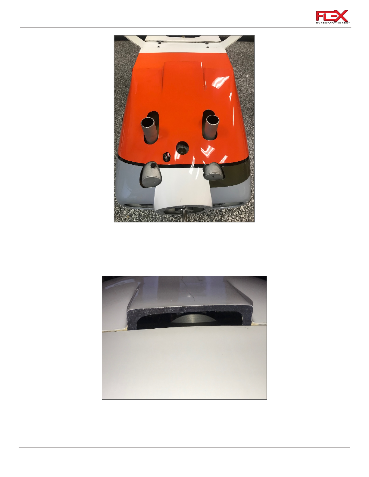
RV-8 70cc FLS Instructions
!
!
2. Every engine and muffler choice will require different openings in the cowling. The
picture above shows a DA-70 with DA mufflers. Other engine brands, single cylinder
engines or other mufflers will require a different cut out. Use a rotary tool with a sanding
drum to cut the holes. Test fit the cowling to be sure there is adequate gap between the
muffler and cowling. We recommend at least 1/8-inch (3mm) gap.
3. Open the rear “lip” in the bottom rear of the cowling with a sanding drum or a rotary tool
as shown in the image above. Be sure to leave approximately 3mm (1/8-inch) of vertical
area to maintain strength in the cowling. Be sure to keep the corners round to help
prevent cracking.
54
Page 59
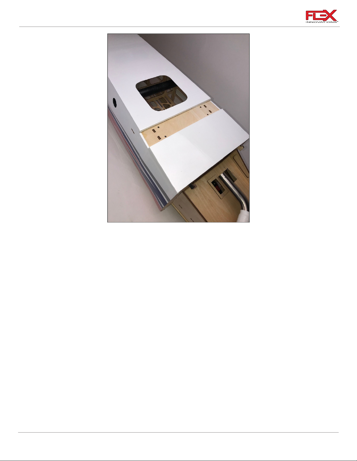
RV-8 70cc FLS Instructions
!
4. For the fuselage exit hole, use a hobby knife with a #11 blade to open the rectangular
hole in the bottom of the fuselage. Be sure to leave about 1/8-inch (3mm) overlap so that
you can iron the covering to the sheeting on the inside of the fuselage. You may need to
cut a few slits in the edge of the covering due to the curved shape of the holes. Apply
some epoxy to the edges of the covering to help prevent oil and debris from getting
under the covering.
55
Page 60
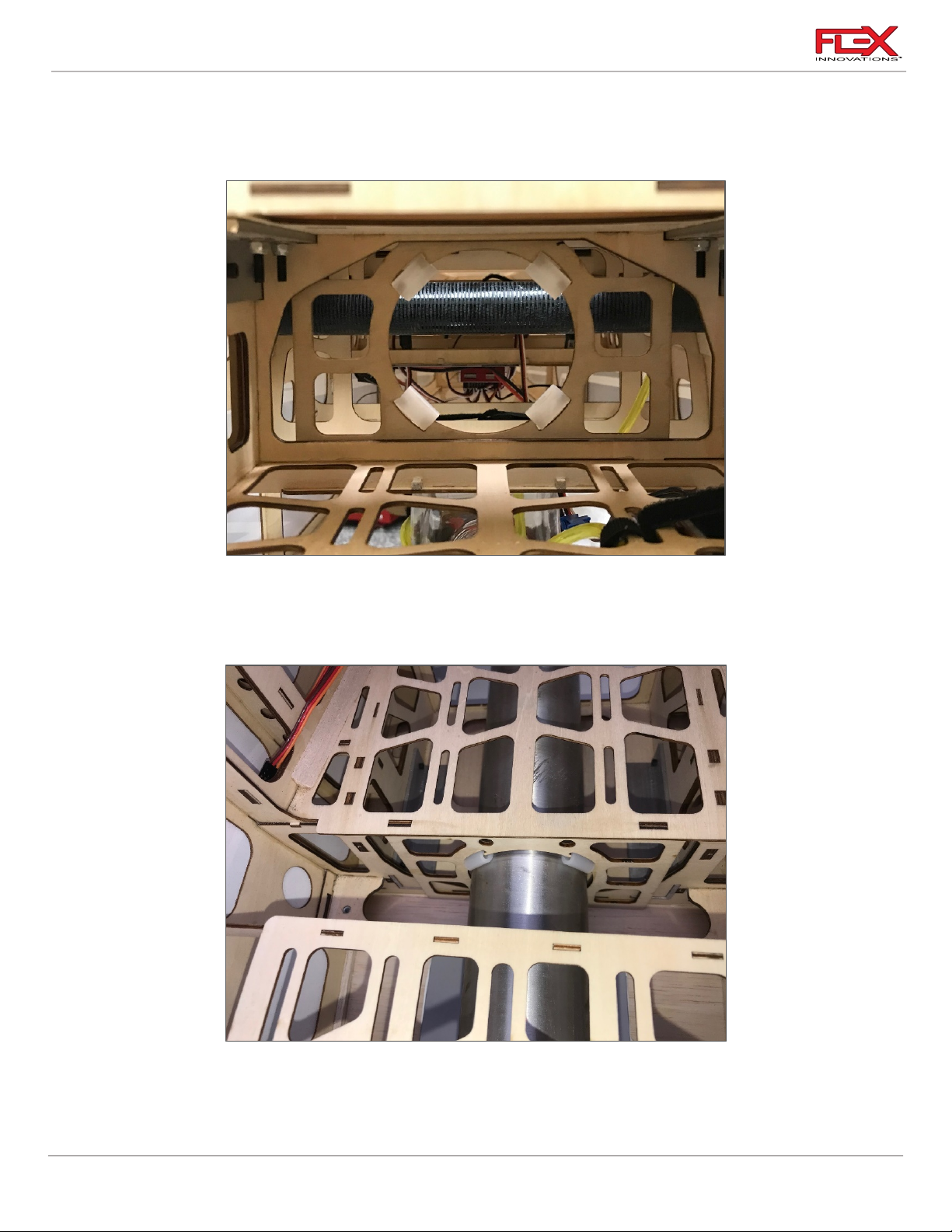
RV-8 70cc FLS Instructions
!
!
Canister Installation (B)
Recommended canister and headers for the different engines are listed in the front section of the
manual.
1. Install the exhaust on the engine using the hardware provided with your engine. Follow
your engine manufacturer's installation instructions. Typically, most engines will use a
gasket between the muffler and cylinder and the socket head cap screws will pass
through a lock washer before securing the muffler to the cylinder.
2. Place the mount in the location shown in the image above. Do not glue it in place at this
time. Install the header and canister per your engine and exhaust manufacturer’s
instructions, placing the exhaust through the mount. Once the exhaust is mounted to the
engine, use 30-minute epoxy to secure the canister mount in place.
56
Page 61

RV-8 70cc FLS Instructions
!
3. The images above show the typical DA-70 with a 2 to 1 header for a single canister. The
header has been cut short by 28mm (1-3/32 in) in length to fit appropriately. The header
has been cut 28mm to fit the length. Note that during testing, Quique was very pleased
with the engine performance, even though the header was trimmed.
57
Page 62
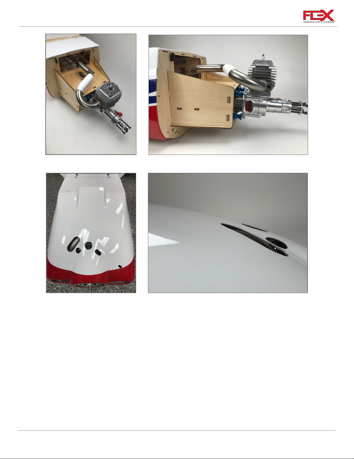
RV-8 70cc FLS Instructions
!
!
4. The images above show the DA-60 with header for a canister install.
5. Every engine and exhaust choice will require different openings in the cowling. The
images above show a DA-70 with 2 to 1 header install. Use a rotary tool with a sanding
drum to cut the holes.
58
Page 63
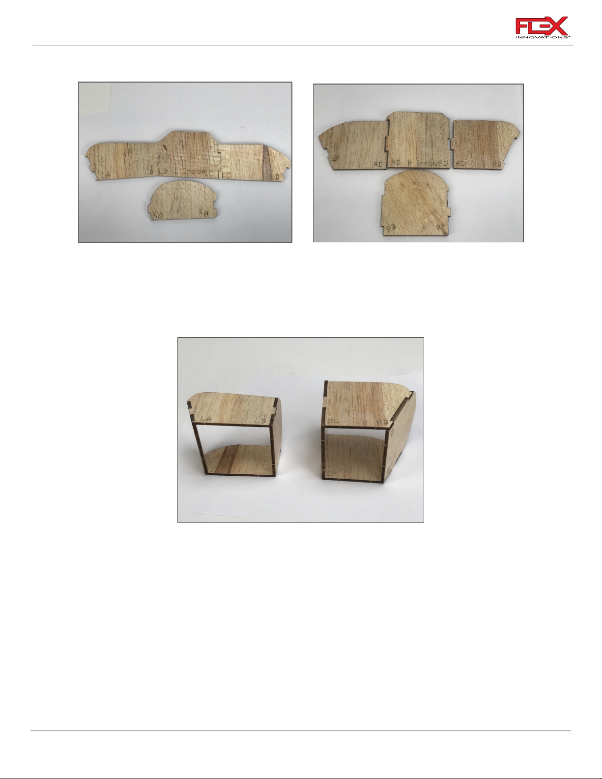
RV-8 70cc FLS Instructions
!
!
Baffle and Final Cowling Installation
1. Locate the engine baffles. These are designed to fit the DA-70 The baffles are labeled
according to their locations. The lettering should face the outside of the baffles when
assembled.
L = Left Baffle
R = Right Baffle.
2. Using medium CA, build the baffles as shown in the image above. Each piece has
markings that should assist you in assembly. On the corner of each baffle is two letters.
Match the letters for the proper assembly. Note the lettering should face to the outside of
the baffles.
Once assembled and the CA has fully cured, you can paint the baffles with enamel-based
paint to help with appearance and help resist damage from fuel or oil. There may be
some final tuning required. If you are using a different engine, you can use these as a
template or modify them as necessary.
59
Page 64

RV-8 70cc FLS Instructions
!
3. Using medium CA, tack each of the baffles into position. The longer baffle goes in the
right-hand side of the cowling. Install the cowling and see if any adjustments are needed
for any interference with the engine. Using colored silicone (we use black so that it
matches the baffling paint), cover all the joints on the inside of the cowling to
permanently fix it in place. Let the silicone cure per the manufacturer’s
recommendations. We choose to use silicone due to the high vibration in this area. Set
aside and let it dry for at least for at least 12 hours to fully cure.
60
Page 65
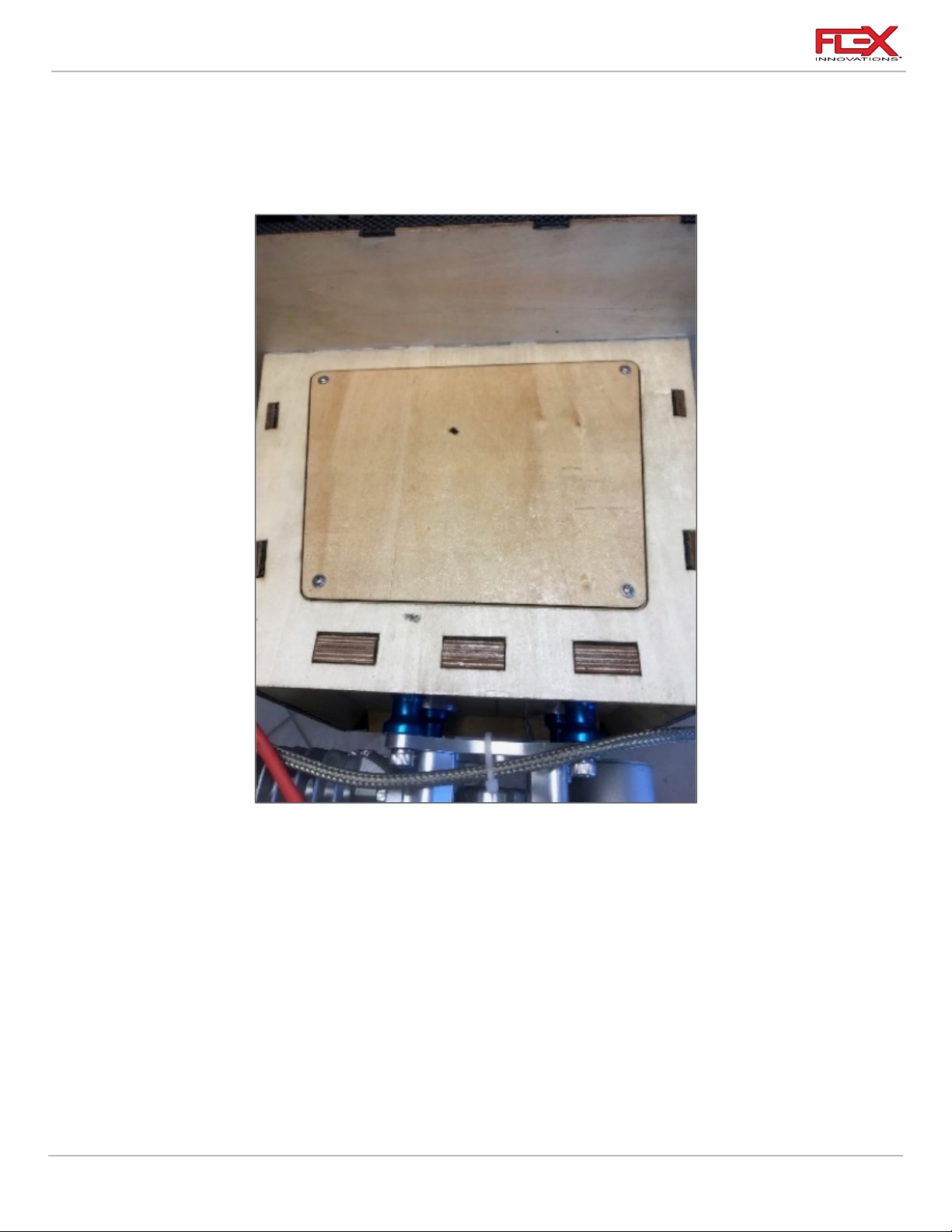
RV-8 70cc FLS Instructions
!
!
!
!
!
4. Install the manual choke linkage using your preferred method. You could use a 2mm ball
link and 2mm linkage found on many 60-class ARF or ARFSV aircraft. We leave the
pushrod long until the cowling is installed and then trim it for the proper length. Be sure
to make a hole in the cowling for the rod and use a grommet or piece of fuel tubing to
serve as a guide for the rod and help prevent any wear to your cowling.
5. Locate the motor box top plate and the (4) M2.5 x 8 wood screws. Use a #1 Phillips
screwdriver to thread an M2.5 x 8 screw into each of the pre-cut holes in the motor box
for the top plate. Remove the screw and apply a small amount of thin CA to each of the
holes to harden the threads cut by the screw. Let the CA fully cure before proceeding.
6. Secure the top plate in place using a #1 Phillips screwdriver.
7. Before installing the cowling, verify that all spark-plug wires, fuel lines and any battery or
servo wires are correctly installed and well-secured.
8. Once you are happy with the fit of your cowling, proceed to installing the cowl. Use a
2.5mm hex driver, (4) M3 x 20 socket head cap screws and (4) M4 flat washers to secure it
in place. All four screws are installed from the inside of the fuselage. Two screws are
located near the top, outside edges of the cowling. The other two are located slightly
below the middle, outside edges of the cowling.
61
Page 66
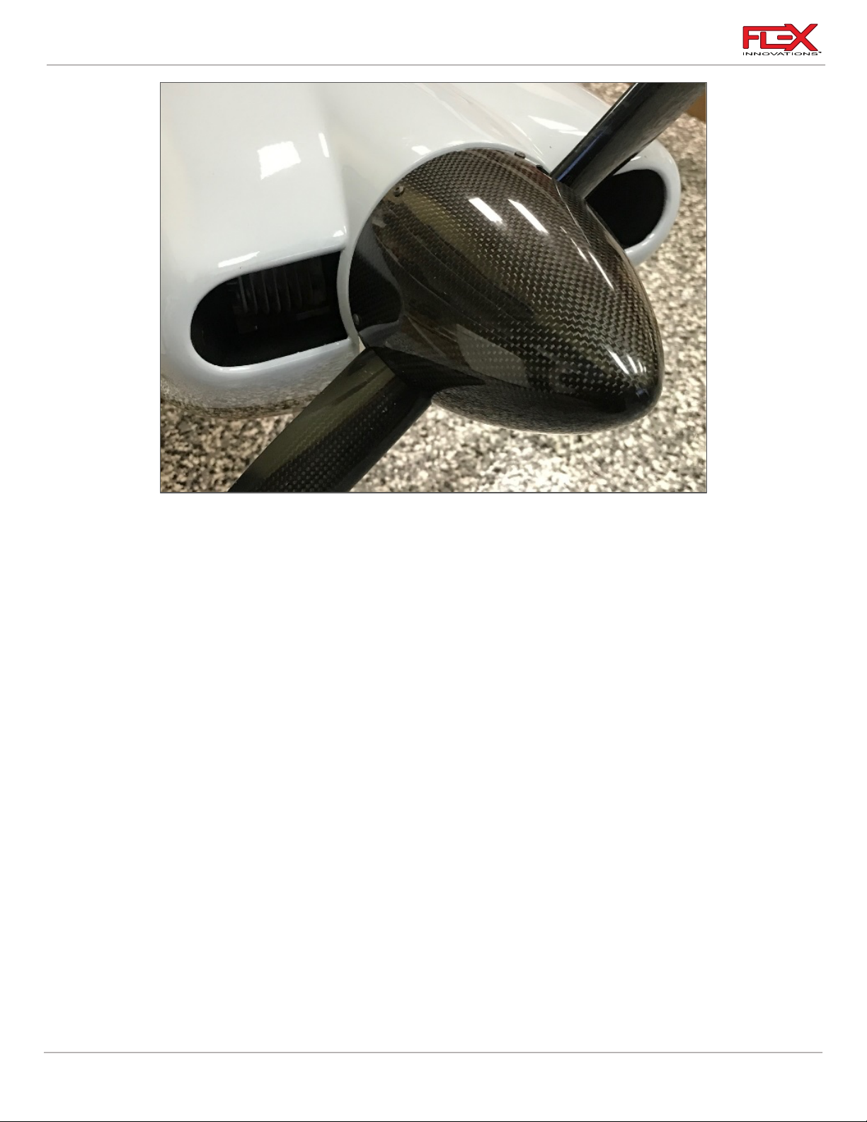
RV-8 70cc FLS Instructions
!
9. Install your propeller and spinner. For the DA-70, we recommend a Falcon 25x8W carbon
fiber propeller and a Falcon 5-inch (127mm) carbon fiber spinner.
62
Page 67

RV-8 70cc FLS Instructions
Required for this section
Components
Tools
Adhesives/Building Materials
o Fuselage Assembly
o Motor
o M5x15 Socket Head Cap
Screw (4)
o M5 Flat Washer (4)
o 1/4x3/4 Socket Head Cap
screw (4)
o ¼ Flat Washer (4)
o 2.5in (63mm) Standoff (4)
o M5x15 Socket Head Cap
Screw (4)
o M5 Flat Washer (4)
o 2mm Hex Driver
o #1 Phillips Screwdriver
o Blue Thread Lock
o 5min Epoxy
o Mixing Cups
o Mixing Sticks
ELECTRIC POWER SETUP
The RV-8 70cc FLS was designed for electric power as well.
Flight time with the recommended equipment is around 5 to 6 minutes with proper throttle
management, leaving you with good reserve. Slow flight and touch and goes can be up to 10
minutes long.
For your first flights on the recommended setup, set your timer for 4 minutes and check the
remaining capacity when charging your batteries. Adjust the timer according to your particular flight
style
Recommended Electric Power System:
o Potenza 65cc 185kV Motor (FPZM65CC)
o (4) 2.5 in (63mm) motor standoffs
o Potenza 6S 6200mAh 40C batteries (two in series for 12S)
o Castle Edge 160HV ESC
o Mejzlik 25 x 12S Propeller
MOTOR INSTALLATION
63
Page 68
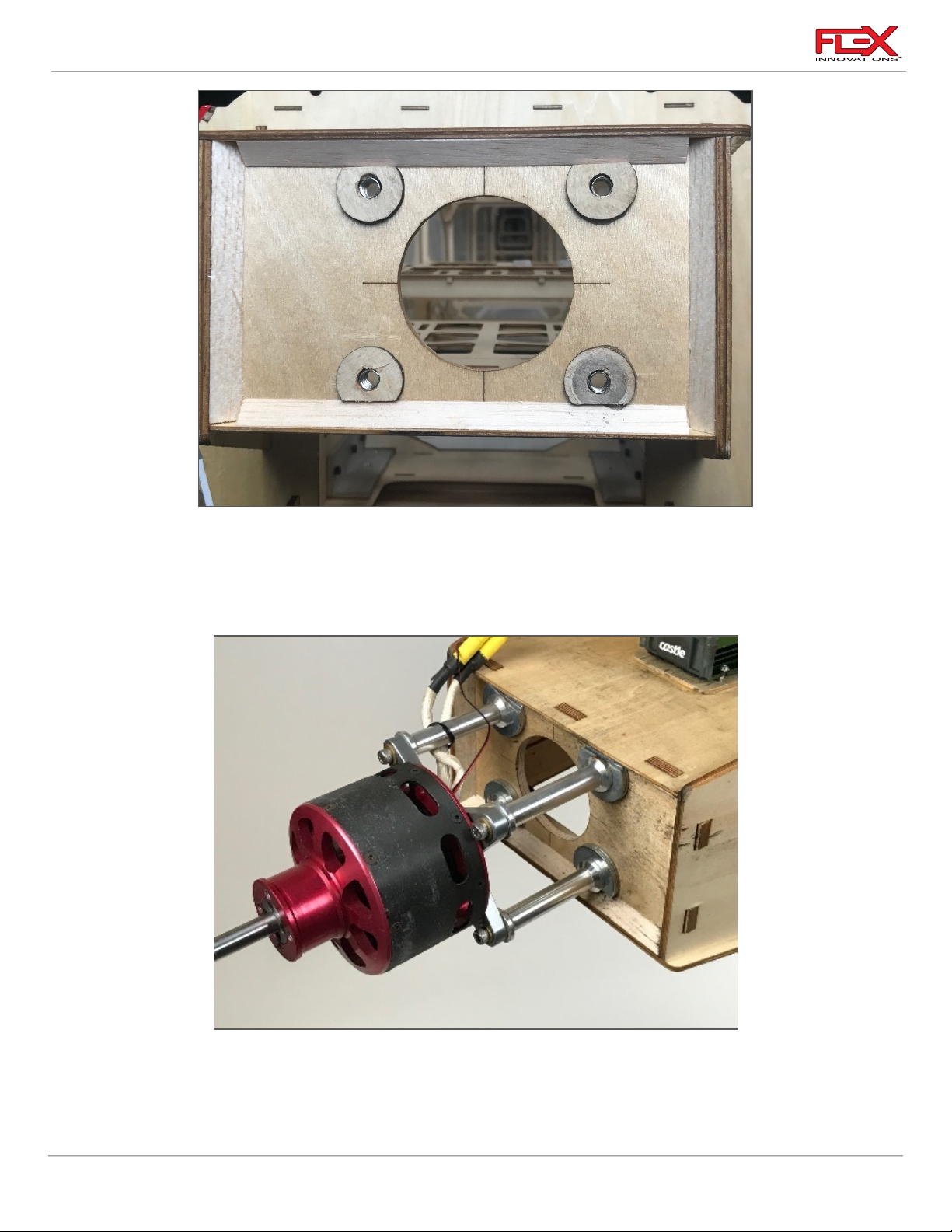
RV-8 70cc FLS Instructions
!
!
!
!
1. The 63mm motor standoffs used are threaded for ¼ -20 bolts on the firewall side and
5mm bolts on the motor side.
2. Using 5-minute Epoxy, glue the (4) 3mm plywood washers to the firewall. This will
provide the correct clearance between the spinner and cowling.
3. Use (4) 1/4 x 3/4-inch socket head cap screws and (4) 1/4-inch washers to mount the
motor. Be sure to apply blue thread lock when securing them.
4. Install the motor using (4) M5 x 10 socket head cap screws with (4) M5 washers. Be sure to
use blue thread lock when securing them.
64
Page 69
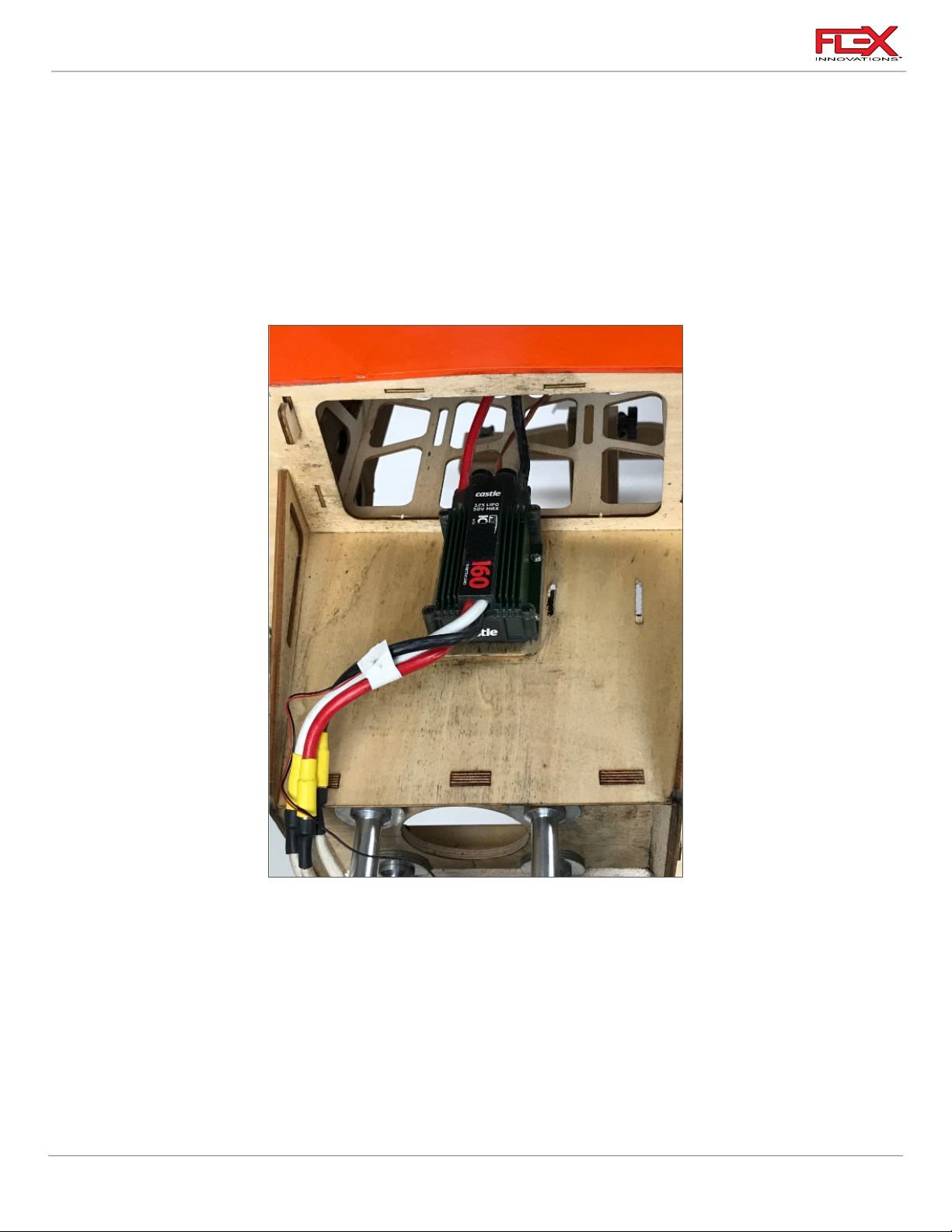
RV-8 70cc FLS Instructions
Required for this section
Components
Tools
Adhesives/Building Materials
o Fuselage Assembly
o ESC
o M2x12 Phillips Head Self-
Tapping Screws (4)
o #1 Phillips Screwdriver
o Drill
o 1.5mm Drill Bit
o Thin CA
!
!
ESC INSTALLATION
1. Mount the ESC on the bottom of the motor box as shown in the picture above. This is a
great location for cooling. Mark the mounting hole locations and use a 1.5mm drill bit to
drill holes in the mounting locations on the motor box. Using a #1 Phillips Screwdriver,
thread an M2 x 12 Phillips-head self-tapping screw into each of the holes. Remove the
screw. Use thin CA to harden the threads, and once the CA has fully cured, you can install
your ESC.
2. Tidy up and secure all the wiring.
65
Page 70
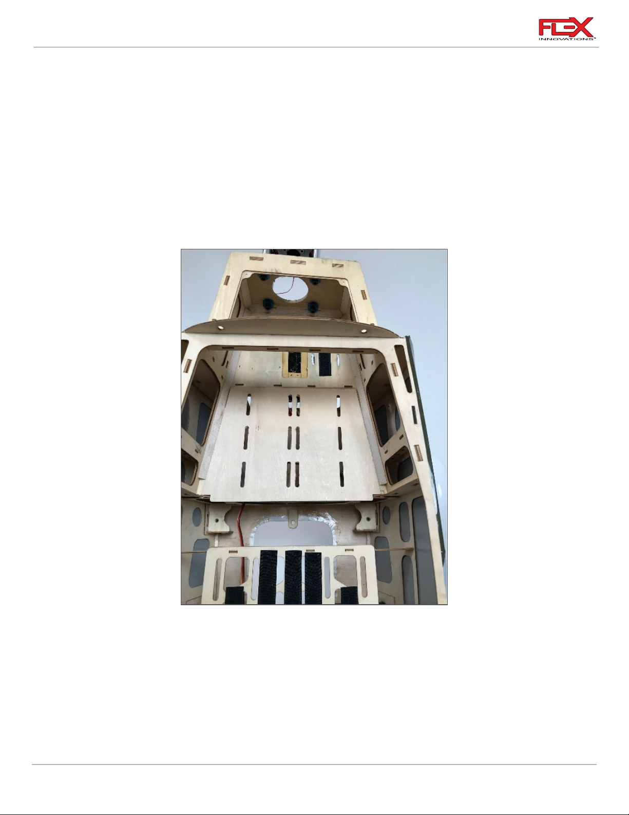
RV-8 70cc FLS Instructions
Required for this section
Components
Tools
Adhesives/Building Materials
o Fuselage Assembly
o Electric Battery Tray
o Sticky Velcro
o Flex Innovations Battery
Hook and Loop Strap
Medium 30mm Long (4).
FPMA1016
o 30 Minute Epoxy
o Mixing Cups
o Mixing Sticks
!
BATTERY TRAY INSTALLATION
1. Using 30-minute epoxy, glue the battery tray on top of the front battery location. This
piece is required to strengthen the area for the increased weight of the electric flight
batteries. Let the epoxy cure before proceeding with the next step.
66
Page 71
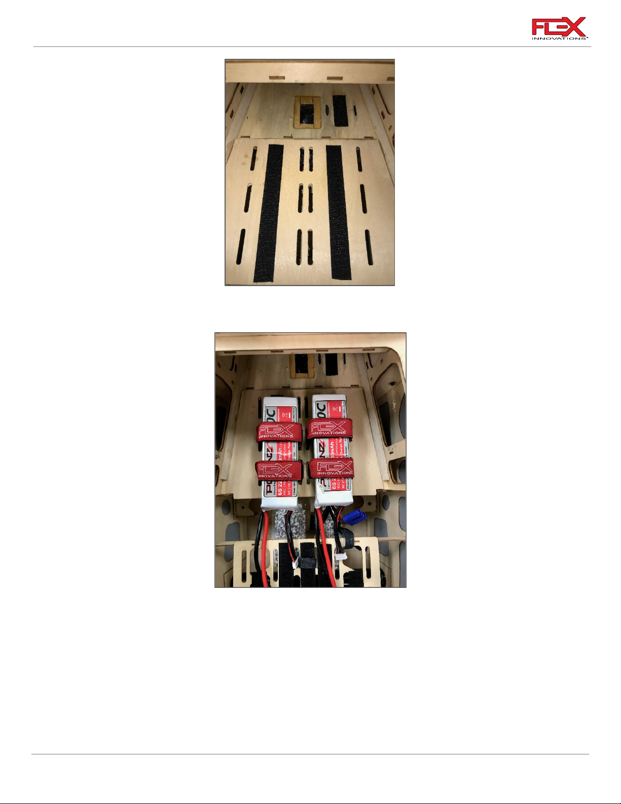
RV-8 70cc FLS Instructions
!
2. After the epoxy cures install adhesive-backed hook and loop tape as shown in the above
picture. Adjust battery the slots as needed.
Quique’s Tip:
o For proper CG on our prototype, the motor batteries are mounted in the location shown in
the image above. The receiver batteries are located at the rear edge of the receiver tray, and
the rudder servo is mounted in the tail of the fuselage.
o If adjustments are needed for proper CG, you can move one motor battery to the fuel tank
mounting tray, or also move the rudder servo forward to the pull-pull location under the
canopy. NOTE: In its stock form, the fuel tank tray cannot support heavy batteries and high
stress loads. If you need to mount batteries here to achieve CG, you should use some 1/8-inch
ply and laminate it over the existing tray for added rigidity.
67
Page 72

RV-8 70cc FLS Instructions
!
!
3. Install four 300mm (11-3/4 inch) Flex Innovations Hook and Loop straps through the slots
in the battery tray to secure the electric flight batteries.
MOTOR/ESC COOLING
1. When using the electric power setup, we recommend that you do not use the provided
baffles for gas engines. The front openings provide enough cooling for the electric motor
and ESC.
For cooling air exhaust, open the rear lip on the bottom of the cowling and the hole in
the bottom of the fuselage just behind the landing gear mount.
68
Page 73
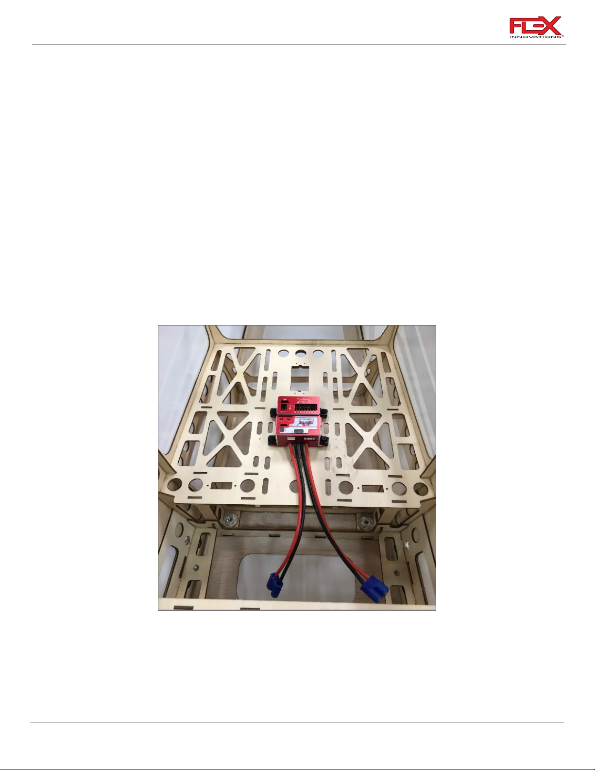
RV-8 70cc FLS Instructions
Required for this section
Components
Tools
Adhesives/Building Materials
o Fuselage Assembly
o Receiver
o Receiver Switch
o Aura Professional
(Optional)
o Receiver Batteries
o Hook and Loop Straps
o Adhesive-Backed Hook
and Loop Tape
o Tie-Wraps
o Hobby Knife with #11
Blade
o 2mm Hex Driver
o #1 Phillips Screwdriver
o Thin CA
!
FINAL ASSEMBLY
RADIO INSTALLATION
1A. If you are using an Aura Professional, it can be mounted forward of the rudder servo
69
location as shown in the picture above. There are pre-cut holes to start the mounting
screws easily. DO NOT use hook and loop tape to mount the Aura.
Use a #1 Phillips screwdriver to thread an Aura mounting screw into each of the pre-cut
holes in the mounting tray. Remove the screw and apply a small amount of thin CA to
Page 74
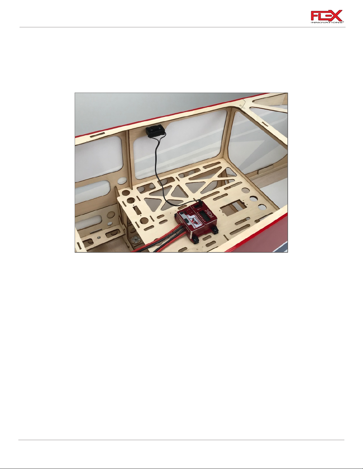
RV-8 70cc FLS Instructions
!
!
each of the holes to harden the threads cut by the screw. Let the CA fully cure before
mounting the Aura and securing the (4) screws.
1B. If not using the Aura, choose a mounting location for your receiver. It can be mounted in
the same location as the Aura in the image above if desired. Keep your CG in mind as well
when choosing a mounting location. We recommend using hook and loop tape on the
back of the receiver, as well as a hook and loop strap to secure it in place.
2. Locate the receiver switch location just under the canopy, and just in line with the Aura &
receiver area as indicated in the picture above. Note that there are switch locations on
both sides of the fuselage to suit your preference. Remove the covering from the hole of
your choice using a hobby knife with a #11 blade. Mount your switch, being sure to orient
the on/off plate properly. If your switch mounting screws thread into metal fittings or
nuts, be sure to use blue thread lock. If your switch mounting screws thread into plastic,
DO NOT use thread lock as it may damage the plastic.
70
Page 75
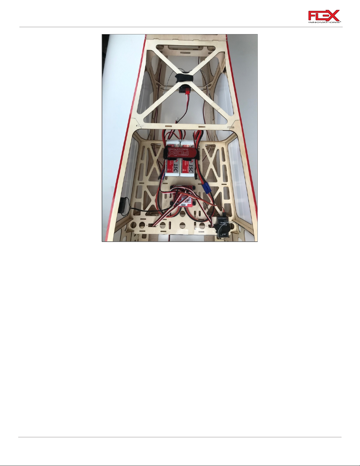
RV-8 70cc FLS Instructions
!
3. Make all necessary servo connections to your receiver and/or Aura. Install the two
recommended receiver batteries as needed to achieve the proper CG. This picture uses
the rudder servo in the tail with a push/pull setup and the DA-70 engine.
In the image above, we are using the Aura 8 Pro with dual Futaba S.Bus receivers. One is
mounted in the tray and the other behind and above for maximum signal strength.
Reference your receiver’s instruction manual for mounting details.
71
Page 76
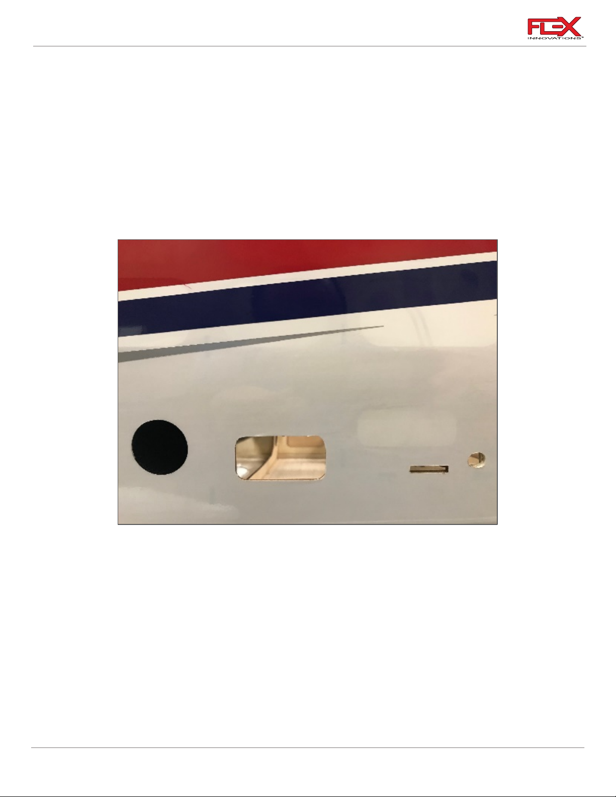
RV-8 70cc FLS Instructions
Required for this section
Components
Tools
Adhesives/Building Materials
o Fuselage Assembly
o Right and Left Wing
Panels
o Carbon Fiber Wing Tube
o M4x15 Socket Head Cap
Screw (4)
o M4 Flat Washer (4)
o 3mm Hex Driver
o Hobby Knife with #11
Blade
o Covering Iron or Trim
Iron
!
!
WING INSTALLATION
1. Use a hobby knife with a sharp #11 blade to remove covering from these holes. Be sure to
leave 1/8-nch (3mm) overlap inside the hole and use a covering or trim iron to seal the
covering into the fuselage.
2. Insert the carbon fiber wing tube into the fuselage ensuring that it is roughly centered.
72
Page 77
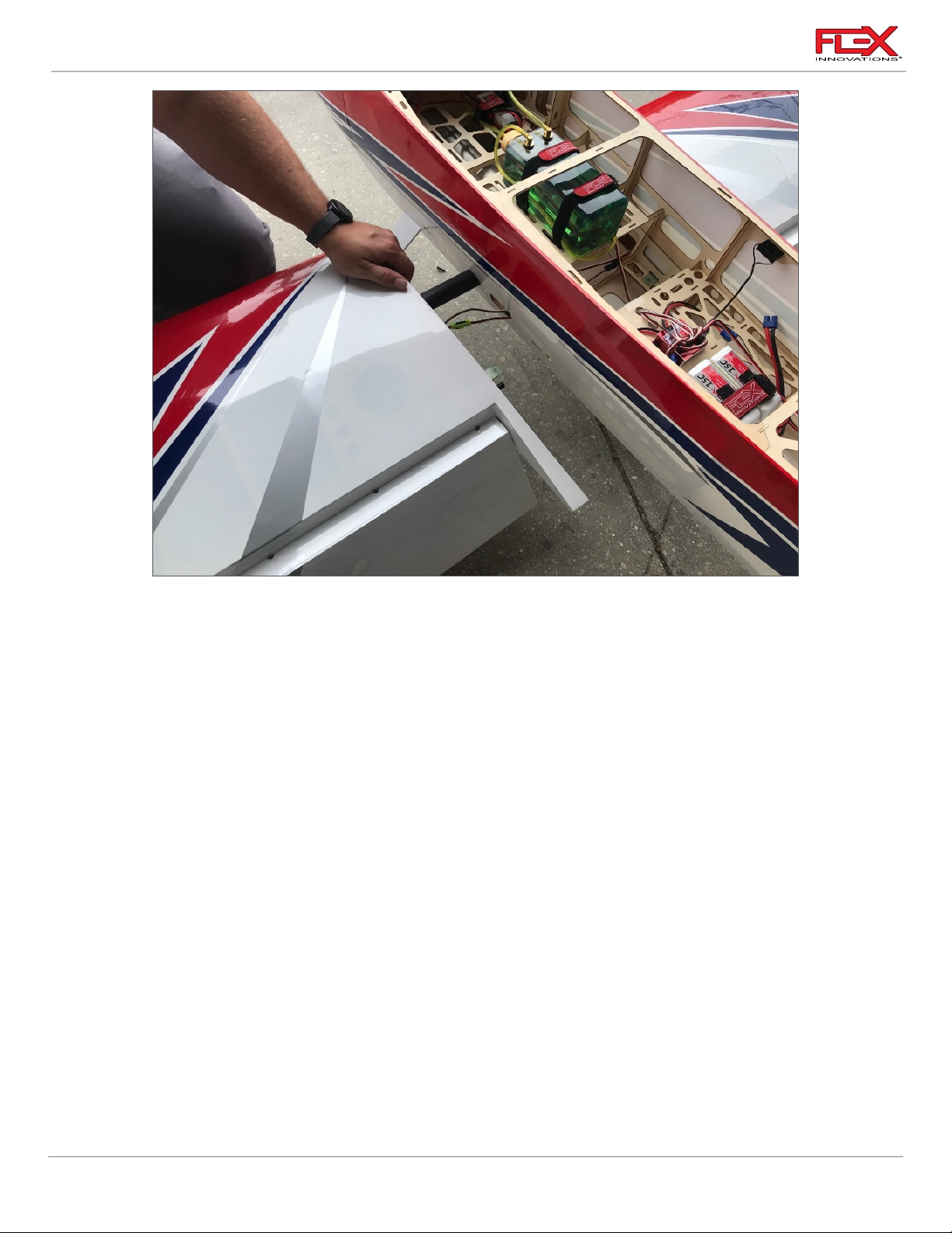
RV-8 70cc FLS Instructions
!
3. Slide one wing panel onto the wing tube. Feed the aileron and flap servo leads through
the fuselage opening. Continue pushing the wing onto the tube until it is fully seated
against the side of the fuselage. Ensure the servo wires are routed properly into the
fuselage. Make sure the wing tube doesn't slide out the other side of the fuselage, and
that the fiberglass wing tabs align with the slots in the wing before fully seating the wing
against the fuselage.
73
Page 78
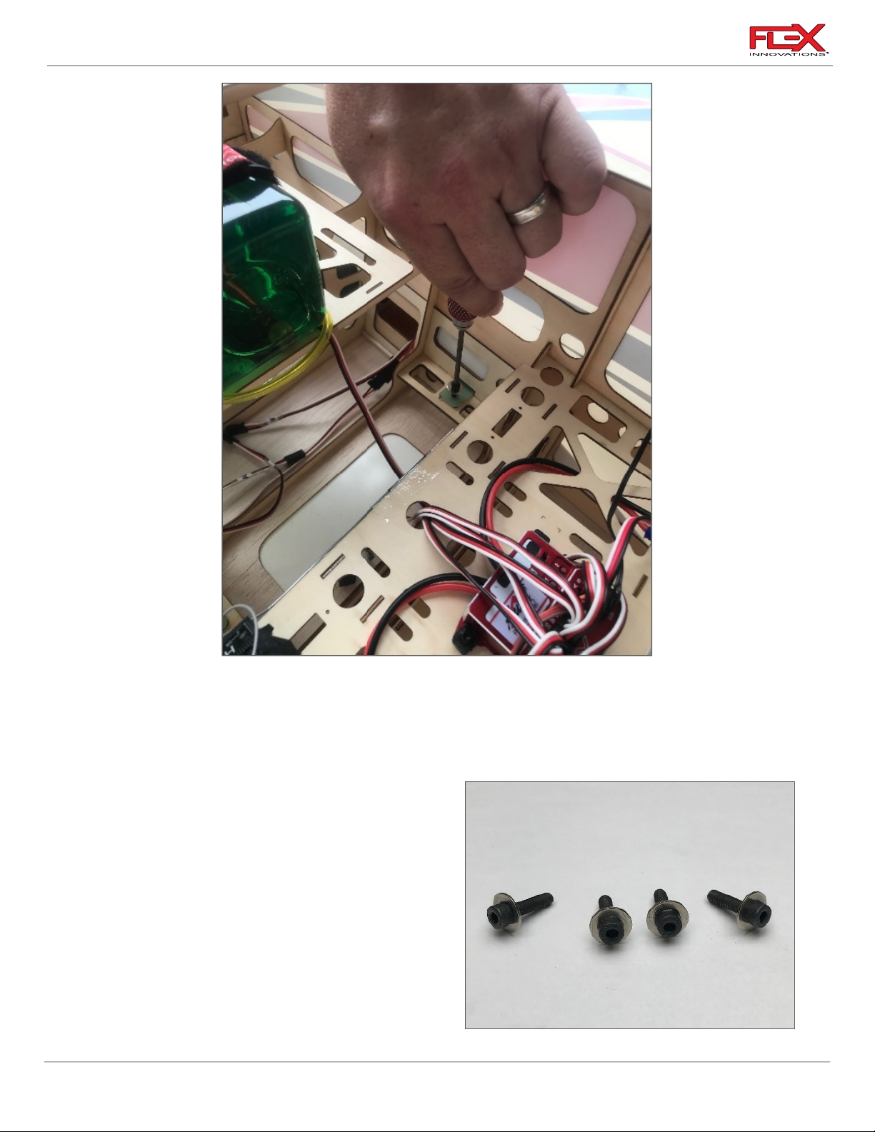
RV-8 70cc FLS Instructions
!
!
4. Secure each wing panel with two M4x15 socket head cap screws and two M4 flat washers
using an M3 hex driver. Repeat the process for the other wing panel.
5. Connect the aileron and flap leads to their corresponding extensions connected to the
Aura, or to your receiver if Aura is not used.
Quique’s Tip:
Using medium CA, glue the (4) M4 flat washers to
the (4) M4 x 15 socket head cap screws. This will
assist in the assembly of the model.
74
Page 79
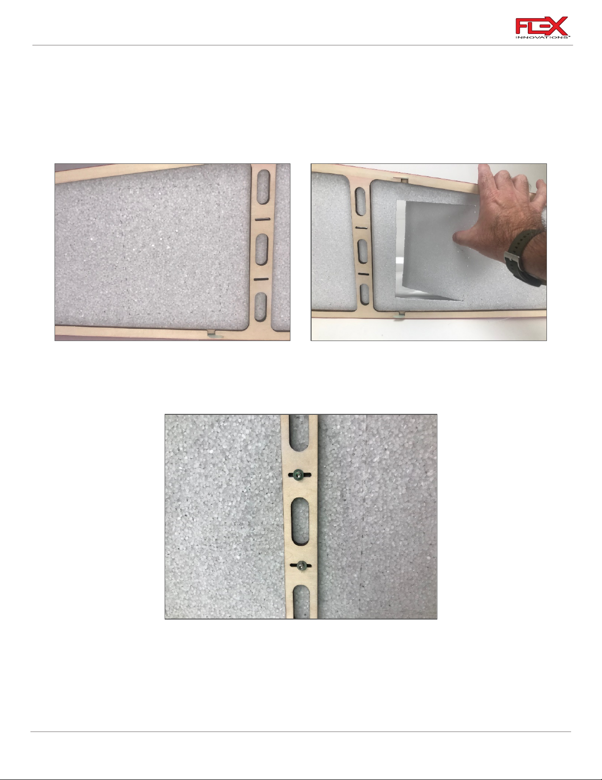
RV-8 70cc FLS Instructions
Required for this section
Components
Tools
Adhesives/Building Materials
o Pilot
o Canopy
o Hobby Knife with #11
Blade
o Medium CA
!
!
PILOT INSTALLATION (OPTIONAL)
1. The foam cockpit floor has a dotted line denoting the cutout area. Take a #11 blade and
cut three of the four side of the rectangle as shown in the picture above. This will allow
you access for mounting the pilot. Once you mount the pilot, glue the foam back in place
using medium CA.
2. The canopy hatch already has a cross-member for the pilot installed. In the image above,
the two slots are for two M3 screws and M3 washers to secure the pilot in place. They do
not have to be used.
75
Page 80
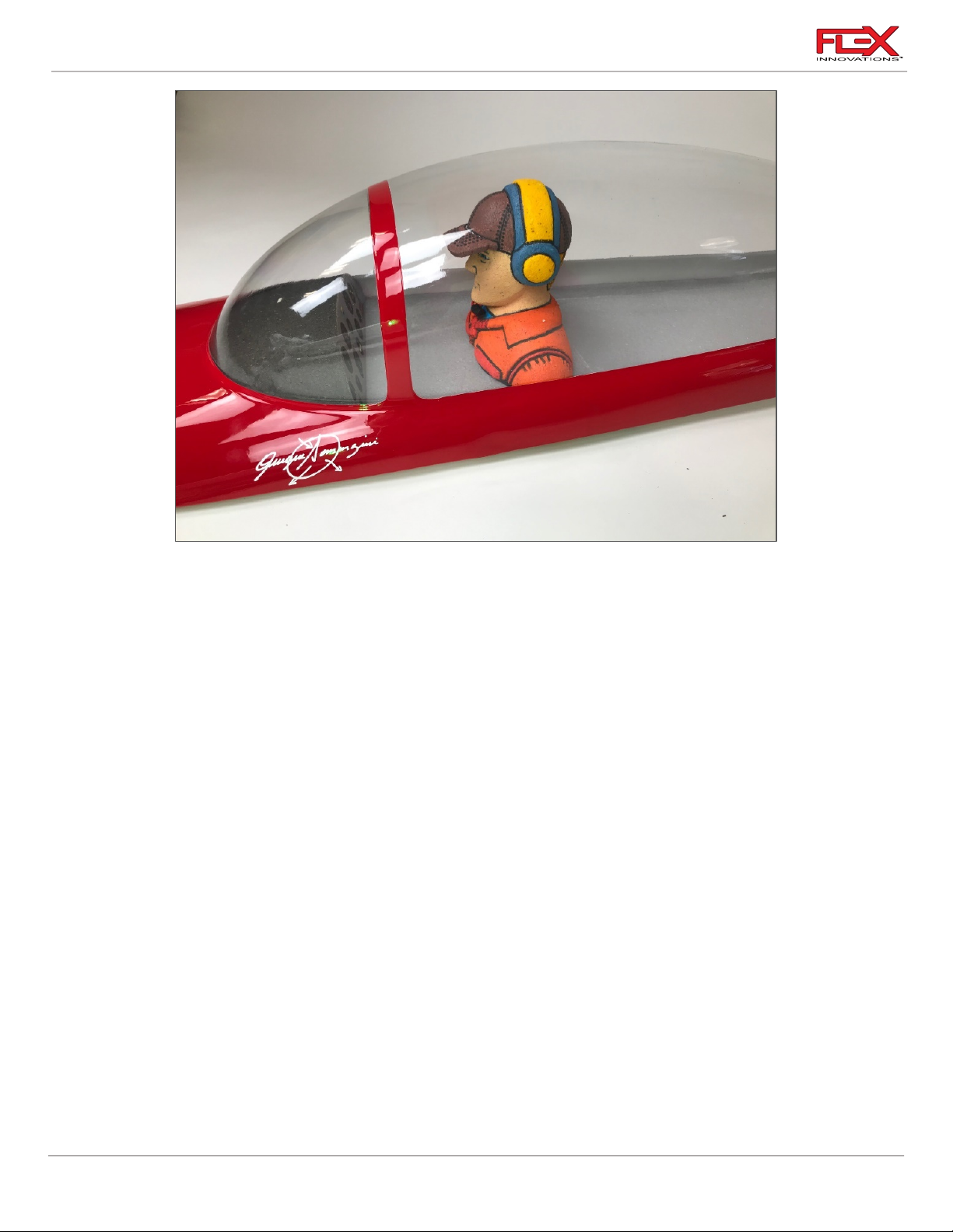
RV-8 70cc FLS Instructions
!
Required for this section
Components
Tools
Adhesives/Building Materials
o Fuselage Assembly
o Canopy
o M3x20 Socket Head Cap
Screw (2)
o M4 Flat Washer (2)
o 2.5mm Hex Driver
!
3. In the full-size RV-8, the pilot sits in the front seat when flying solo. Your installed pilot
should appear like the image above.
CANOPY INSTALLATION
1. As noted at the beginning of this manual, the canopy has hooks along the sides to help
secure the canopy in place without the use of additional screws. Place the canopy flat,
and slightly aft of its final location, noting to align these hooks with the slots in the
fuselage. Gently push the canopy forward until it reaches the cowling and sits
appropriately in place.
76
Page 81
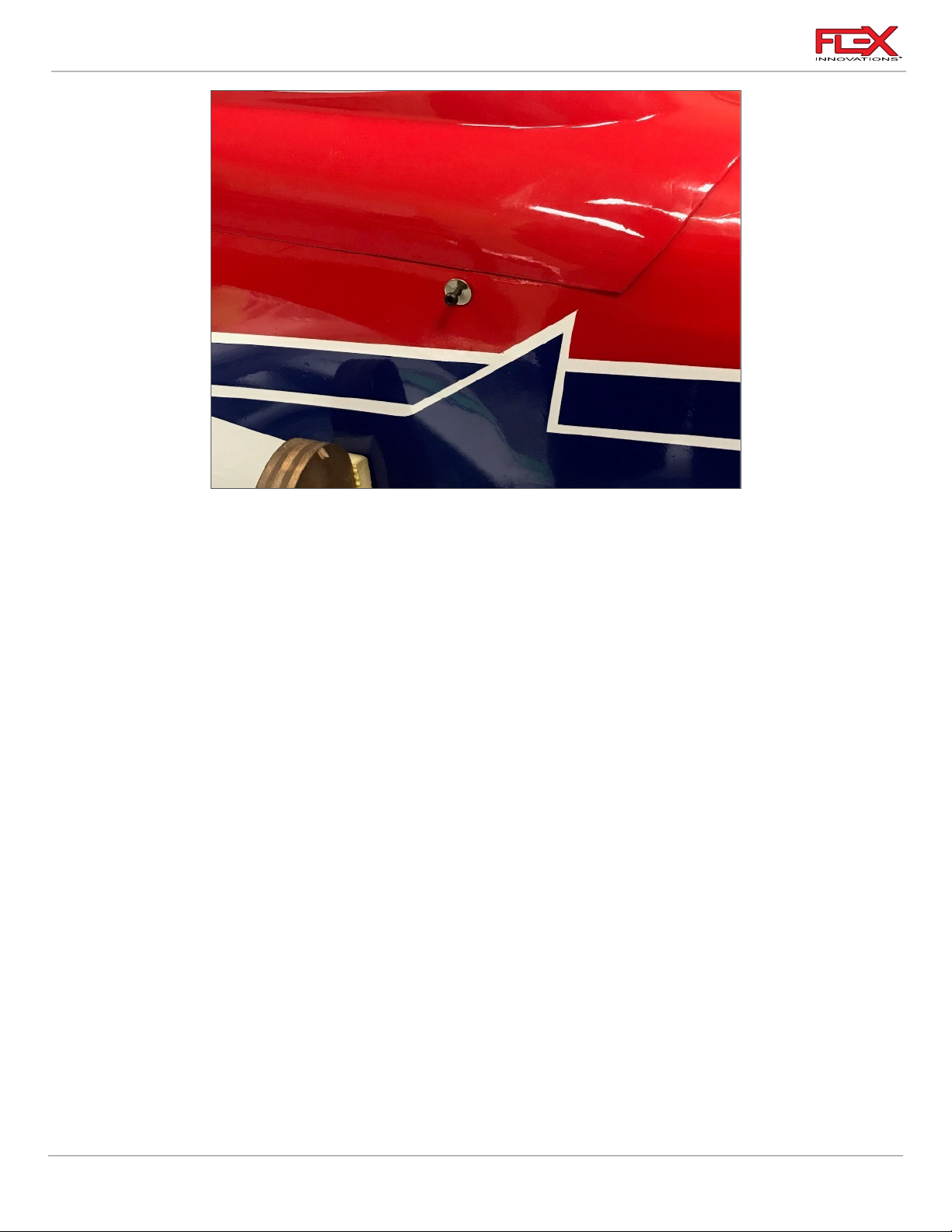
RV-8 70cc FLS Instructions
!
!
!
!
!
!
2. Using your 2.5mm hex driver, secure the canopy with two M3x20 socket head cap screws
and two M3 flat washers through the holes in the fuselage towards the rear of the
canopy, one on each side.
DECAL INSTALLATION
A traditional set of clear decals is provided with the RV-8 70cc.
However, if you want the very best finished appearance, we recommend the Premium Vinyl Graphics
Kit made by Callie Graphics and sold by Flex Innovations. The part numbers are listed below.
FPM2022 RV-8 70cc Premium Vinyl Graphics Kit - Red
FPM2023 RV-8 70cc Premium Vinyl Graphics Kit - Camouflage
Use the drawings provided below for a guide to apply decals to your model.
1. Thoroughly clean the model to ensure it is free of oil, fingerprints, and dust.
2. Separate the decals, but do not remove the paper backing.
3. Prepare a dishpan or small bucket with a mixture of warm water and liquid dish
detergent. The ratio should be approximately one teaspoon per gallon of water.
4. Submerse the decal into the water/soap mixture and gently remove the paper backing.
Removing the backing under water prevents fingerprints from being visible on the back
side of the decal
5. Apply some water/soap mixture with your palm to the area desired. Once the area is
saturated, position the sticker on the airplane. Even though these are not water transfer
77
Page 82

RV-8 70cc FLS Instructions
!
!
!
INNOVATIONS
TM
INNOVATIONS
TM
decals, using wet application methods allows the sticker to be repositioned, reduces
bubbles, and eliminates fingerprints and other blemishes from being visible.
6. Hold the decal in place and use a paper towel to gently wipe most of the water away.
7. Use a soft piece of balsa or similar to squeegee out the remaining liquid from underneath
the decal.
8. Repeat the process until all decals are applied. Do not move, or otherwise touch the
model for at least 24 hours to allow adequate time for the remaining water to evaporate.
RV-7 70cc FLS – Red Scheme
78
Page 83
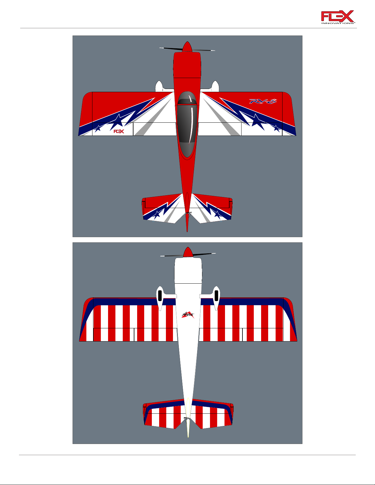
RV-8 70cc FLS Instructions
INNOVATIONS
TM
35.0000
35.0000
Aura
79
Page 84

RV-8 70cc FLS Instructions
INNOVATIONS
TM
INNOVATIONS
TM
ULTRACOTE COLORS
TRUE RED (HANU866)
MIDNIGHT BLUE (HANU885)
SILVER (HANU881)
WHITE (HANU870)
80
Page 85
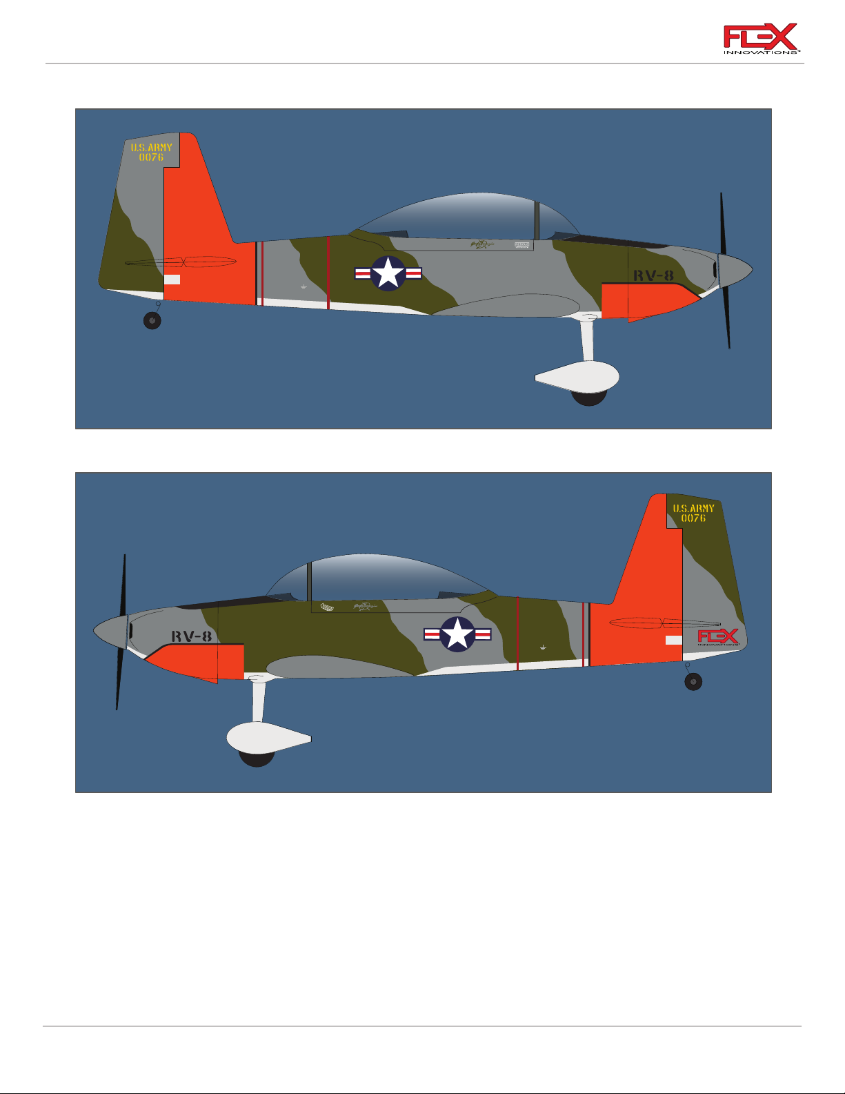
RV-8 70cc FLS Instructions
ARMY
GROUND EARTH HERE
ARMY
GROUND EARTH HERE
RV-8 70cc FLS – Camouflage Scheme
81
Page 86
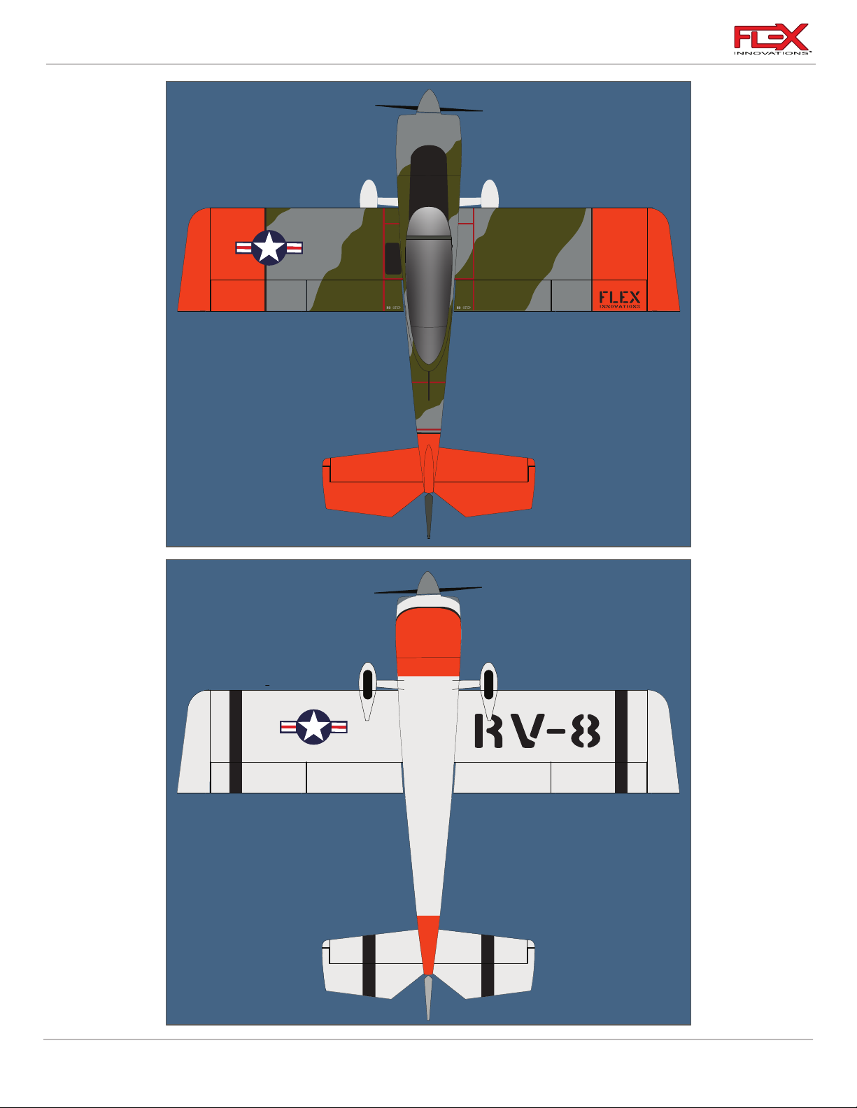
RV-8 70cc FLS Instructions
U.S.ARMY
82
Page 87
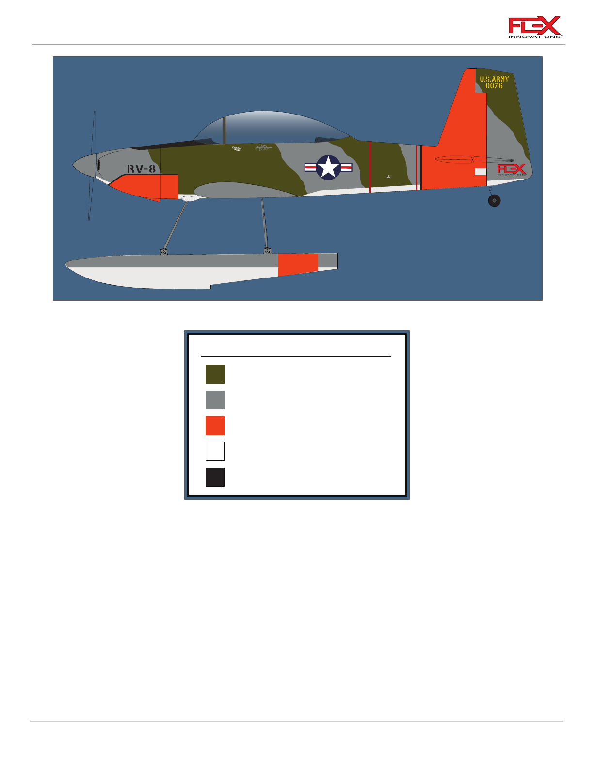
RV-8 70cc FLS Instructions
ARMY
GROUND EARTH HERE
ULTRACOTE COLORS
OLIVE DRAB (HANU904)
LIGHT GRAY (HANU882)
ORANGE (HANU877)
WHITE (HANU870)
BLACK (HANU874)
83
Page 88
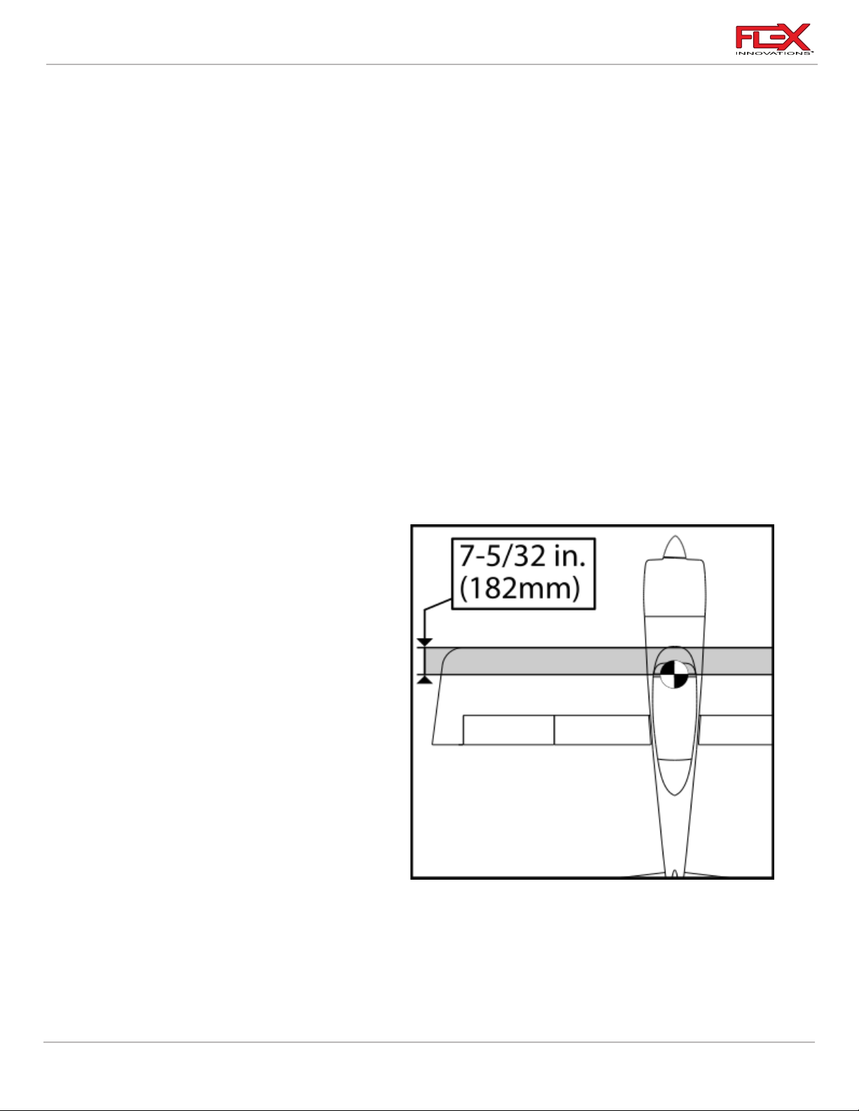
RV-8 70cc FLS Instructions
FINAL SETUP AND FLYING NOTES
CENTER OF GRAVITY
Setting the center of gravity is one of the most important steps for success, particularly with a new
airplane. The Flex Innovations RV-8 70cc FLS is an airplane with a wide performance envelope and
large control surface throws. These two factors combine to make the RV-8 70cc FLS a very enjoyable
aircraft to fly, but if the center of gravity is not within an acceptable range, it will make the airplane
difficult to control. To have the most success and enjoyment from your RV-8 70cc FLS, please follow
the next steps very carefully.
Before balancing your model, please ensure that all of the components are installed in your airplane.
This means the batteries, servos, linkages, hardware, propeller, and spinner. In other words, the
aircraft should be completely assembled as if you were getting ready to fly it. The airplane must be in
ready-to-fly condition (without fuel), otherwise the measurement will not be accurate.
There are several methods for determining the correct center of gravity; from using a CG machine, to
using fingers and a friend. Regardless of the method used, ensure that the tests are accurate and
repeatable. If there are any inconsistencies between measurements, work to isolate the source of the
error(s) to ensure that the test can be repeated with the same results. If lifting the model by the wing
tips, lift at the outside-most wing rib location and not the wing tip itself or damage to the model may
result.
During testing, it was found that the
acceptable CG range on the RV-8 70cc FLS
is 170 to 190mm (6-11/16 to 7-1/2 inches)
AFT from the LEADING EDGE of the wing.
Depending on your flying style and
preference, you should choose a specific
CG within this range.
Quique's Preferred CG:
Through Quique's extensive testing, Quique
has found that he prefers the CG located at
182mm (7-5/32 inches) AFT from the
LEADING EDGE of the wing.
Quique’s Tip:
The CG can be easily achieved using the recommended equipment and placements recommended
in this manual. However, some variance of weight between models is possible. For this reason, it is
recommended to leave the batteries uninstalled and install them in the location necessary to achieve
the recommended CG. There are three battery mounting locations in the aircraft for this purpose.
The forward location is just in front of the fuel tank. A middle position is provided next to the fuel
84
Page 89
RV-8 70cc FLS Instructions
RV-8 70cc Control Throws and Expo
Low Rate
High Rate
(Flaps Do Not Move w/Aileron in Low
Rate)
(Flaps Move & Match Ail in High Rate)
Up
Down
Up
Down
Aileron
130mm (5-1/8 in.)
115mm (4-1/2 in.)
130mm (5-1/8 in.)
115mm (4-1/2 in.)
Elevator
15mm (19/32 in.)
15mm (19/32 in.)
70mm (2-3/4 in.)
70mm (2-3/4 in.)
Rudder
33mm (1-9/32 in.)
33mm (1-9/32 in.)
47mm (1-27/32 in.)
47mm (1-27/32 in.)
Aileron > Flap Mix
0mm (0 in.)
0mm (0 in.)
Even with Aileron
Even with Aileron
Aileron Expo
25%
25%
40%
40%
Elevator Expo
25%
25%
40%
40%
Rudder Expo
10%
10%
20%
20%
Half Flap
Full Flap
Flap Travel
60mm (2-3/8in.)
100mm (3-15/16 in.)
(From Flap Switch)
Flap > Elevator Mix
12%
18%
(Down Elevator)
tank, and the aft position is on the rudder servo and receiver tray, near the back of the canopy.
Choose a location that suits your needs for your specific setup.
AURA 8 PROFESSIONAL
If you choose to use Aura 8 Professional AFCS, you can find the information on the RV-8 70cc FLS
Aura set-up in the Aura Config Tool and in the wiki at:
http://wiki.flexinnovations.com/wiki/RV8_70cc
STARTING CONTROL SURFACE THROWS AND EXPONETIAL
The following throws and exponential have been tested thoroughly during the development of the
airplane and have been determined to be the optimal starting point for the RV-8 70cc FLS. As you
become more familiar with the airplane, you may tweak the rates and expos to better suit your flying
style, but these numbers provide a very good starting point.
NOTE: Aileron throws are measured at the trailing edge and tip of the aileron. Flaps are measured at the
trailing edge of the flap at the aileron. Elevator and rudder throws are measured from the center of
the fin or stab to the center of the counterbalance. Since expo directions vary by transmitter
manufacturer, all expos listed below are those that make the control feel softer around the stick's
center position.
High rate should be reserved for advanced aerobatics and low rate should be reserved for sport
flying and general aerobatics. It is highly recommended that for your first flights, take offs and
landings be done in low rate.
85
Page 90

RV-8 70cc FLS Instructions
!
!
!
!
!
!
!
RANGE TESTING
Carefully follow the binding and range testing instructions included with your radio equipment. If
there are any issues passing the test range, please consult your transmitter and receiver manuals or
contact your transmitter and receiver manufacturer to determine the appropriate solution before
attempting to fly.
BEFORE FIRST FLIGHT
Before going to the field for your first flight, please go over the finished, fully assembled model at
home. The key to a successful first flight is preparation and ensuring that your plane is airworthy.
1. For optimal performance of your model, balance your propeller and spinner. Most
propellers are balanced fairly-well out of the package, however, some fine-tuning can
make a mediocre propeller perform great. An out-of-balance propeller or spinner can
wreak havoc on the electronic components in the airplane, as well as prematurely
shorten the life span of the engine, servos or even the model itself. A balanced propeller
will be quieter, generate more thrust, produce less vibration, and operate more efficiently
than one that is not balanced.
2. Re-check all linkages and connections, including those that may have been assembled by
the factory. Ensure pushrods are sufficiently threaded into ball links, ensure that all metalto-metal connections have thread lock applied and ensure that all controls move freely
and in their proper direction.
3. Verify proper functioning, break-in, and operation of your engine choice. Ensure that the
fuel-air mixture is correct, and that the engine is producing full power. If you are not
familiar with gas engines, ask for the assistance of a more experienced pilot in your area
or speak with your engine manufacturer.
4. Secure any loose wiring inside the fuselage or wings and be sure that they are secured in
a way that they do not rub or chafe.
5. Ensure that all batteries (transmitter, receiver, ignition or flight packs) are fully charged
prior to leaving for the flying field.
6. Take a few moments to assemble the airplane away from commotion, talkative
onlookers, or any other distractions. Ensure that all connections are properly made and
secured, the wing bolts are tight and take a few minutes to plan out your first flight.
7. If your engine is new, avoid prolonged full throttle runs and vertical climbs. Limit the first
few flights to a short flight time. Start off short, gradually lengthening the flight times as
you become comfortable with the performance of your engine. Six minutes is a good
time to limit your first flights to. As you become more familiar with the airplane and begin
to fly it in a more aggressive manner, monitor the temperature of the engine and adjust
the fuel-air mixture according to your engine manufacturer’s recommendations.
86
Page 91

RV-8 70cc FLS Instructions
AMA SAFETY CODE
When flying your aircraft, we recommend following the guidelines set by the Academy of Model
Aeronautics (AMA). You can find their Safety handbook as well as more information on the AMA at
their website, located at the address below.
https://www.modelaircraft.org/
87
Page 92

RV-8 70cc FLS Instructions
FPM2000A
RV-8 70cc FLS, Red
FPM2000B
RV-8 70cc FLS, Camouflage
FPM2050A
RV-8 70cc FLS ARFSV, Red
FPM2050B
RV-8 70cc FLS ARFSV, Camouflage
FPM2001A
RV-8 70cc FLS Fuselage w/o hatches, Red
FPM2001B
RV-8 70cc FLS Fuselage w/o hatches, Camouflage
FPM2002AL
RV-8 70cc FLS Left Wing Panel, Red
FPM2002AR
RV-8 70cc FLS Right Wing Panel, Red
FPM2002BL
RV-8 70cc FLS Left Wing Panel, Camouflage
FPM2002BR
RV-8 70cc FLS Right Wing Panel, Camouflage
FPM2003A
RV-8 70cc FLS Horizontal Stabilizer with Elevators, Red
FPM2003B
RV-8 70cc FLS Horizontal Stabilizer with Elevators, Camouflage
FPM2004A
RV-8 70cc FLS Vertical Stabilizer with Rudder, Red
FPM2004B
RV-8 70cc FLS Vertical Stabilizer with Rudder, Camouflage
FPM2005A
RV-8 70cc FLS Cowling with hardware, Red
FPM2005B
RV-8 70cc FLS Cowling with hardware, Camouflage
FPM2006A
RV-8 70cc FLS Canopy Hatch with cockpit, Red
FPM2006B
RV-8 70cc FLS Canopy Hatch with cockpit, Camouflage
FPM2007
RV-8 70cc FLS Painted Carbon Fiber Landing Gear
FPM2008
RV-8 70cc FLS Wheel Pants with hardware
FPM2009
RV-8 70cc FLS Carbon Wing & Stab Tubes
FPM2010
RV-8 70cc FLS Tail gear with wheel and Hardware
FPM2011
RV-8 70cc FLS Main Wheel and Axle Set (5 in. diameter)
FPM2013
RV-8 70cc FLS Hardware Set
FPM2017
RV-8 70cc FLS Laser Cut Wood Parts
FPM2019
RV-8 70cc FLS Lightweight 24oz Fuel/Smoke Tank
FPM2021
RV-8 70cc FLS Vertical Fin Carbon Fiber Tube
REPLACEMENT PARTS
88
Page 93

RV-8 70cc FLS Instructions
FPM2022
RV-8 70cc FLS Premium Vinyl Graphics Set, Red
FPM2023
RV-8 70cc FLS Premium Vinyl Graphics Set, Camouflage
FPM2016A
RV-8 70cc Float Set, Red
FPM2016B
RV-8 70cc Float Set, Camouflage
FPM2014
Premium Wing and Tail Bag Set, RV-8 70cc FLS
FPM1624
20mm Aluminum Engine Stand Offs
FPMDA70
Desert Aircraft DA-70 engine
FPMDA70MUFLR
Desert Aircraft DA-70 Muffler Set
FPMFAL5CGS
Falcon Carbon Fiber Spinner, 5 inch
FPMHOLYG2
Holy Smokes Gen2 Smoke System
FPMPF249CF
Flex 24x9 Two Blade Carbon Fiber Propeller
FPMPF258WCF
Falcon 25x8W Two Blade Carbon Fiber Propeller
FPZA1036
Aluminum Servo Arm 2-inch Clamping (25T).
FPZA1037
Aluminum Servo Arm 4-inch Clamping (25T).
FPZA1040
Servo Connector Safety Clip Set (10)
FPZAURA08PRO
Aura 8 Professional AFCS
FPZBR20002S15
2S 2000mAh 15C Li-Po Receiver Battery
FPZBR40002S15
2S 4000mAh 15C Li-Po Receiver Battery
FPZDS22209HV
Potenza DS22209 High Voltage, Titanium Gear Servo
FPZDS49010BLHV
Potenza DS49010 Brushless, High Voltage Servo
ISDTD2
iSDT D2 Smart AC Dual Battery Charger 100W x 2
OPTIONAL ACCESSORIES
89
Page 94

RV-8 70cc FLS Instructions
LIMITED WARRANTY
Warranty Coverage
Flex Innovations LLC and its authorized resellers (“Flex”) warrant to the original purchaser that this
product (the “Product”) will be free from defects in materials and workmanship at the date of
purchase.
Outside of Coverage
The warranty is not transferable and does not cover:
(a) Products with more than 45 days after the purchase date
(b) Damage due to acts of God, accident, misuse, abuse, negligence, commercial use, or due to
improper use, installation, operation, or maintenance
(c) Damage to other components or assemblies associated with the use of the Product.
(d) Modification of or to any part of the Product
(e) Product not purchased from an authorized Flex Innovations dealer or distributor.
(f) Product that has been partially, or fully assembled
(g) Shipping damage
(h) Cosmetic damage
(i) Services or labor associated with the repair, use or assembly of the Product.
OTHER THAN THE EXPRESS WARRANTY ABOVE, FLEX MAKES NO OTHER WARRANTY
REPRESENTATION, AND HEREBY DISCLAIMS ALL IMPLIED WARRANTIES, INCLUDING, WITHOUT
LIMITATION, THE IMPLIED WARRANTIES OF NONINFRINGEMENT, MERCHANTABILITY AND
FITNESS FOR A PARTICULAR PURPOSE. THE PURCHASER ACKNOWLEDGES THAT THEY ALONE
HAVE DETERMINED THAT THE PRODUCT WILL SUITABLY MEET THE REQUIREMENTS OF THE
PURCHASER’S INTENDED USE.
Purchaser’s Remedy
Flex’s sole obligation and purchaser’s sole and exclusive remedy shall be that Flex will, at its option,
either (i) service, (ii) replace any part of the Product determined by Flex to be defective, or (iii) replace
the Product determined by Flex to be defective. Flex reserves the right to inspect all Product(s)
involved in a warranty claim. Service or replacement decisions are at the sole discretion of Flex. Proof
of purchase is required for all warranty claims. SERVICE OR REPLACEMENT AS PROVIDED UNDER
THIS WARRANTY IS THE PURCHASER’S SOLE AND EXCLUSIVE REMEDY.
Limitation of Liability
FLEX SHALL NOT BE LIABLE FOR SPECIAL, INDIRECT, INCIDENTAL OR CONSEQUENTIAL
DAMAGES, LOSS OF WAY, REGARDLESS OF WHETHER SUCH CLAIM IS BASED IN CONTRACT,
WARRANTY, TORT, NEGLIGENCE, STRICT LIABILITY OR ANY OTHER THEORY OF LIABILITY, EVEN
IF FLEX HAS BEEN ADVISED OF THE POSSIBILITY OF SUCH DAMAGES.
Further, in no event shall the liability of Flex exceed the individual price of the Product on which
liability is asserted. As Flex has no control over use, setup, assembly, modification or misuse, no
liability shall be assumed nor accepted for any resulting damage and/or injury. By the act of use,
setup or assembly, the user accepts all resulting liability. If you as the purchaser or user are not
prepared to accept the liability associated with the use of the Product, purchaser is advised to return
the Product immediately in new and unused condition to the place of purchase.
90
Page 95

RV-8 70cc FLS Instructions
Law
These terms are governed by Florida law (without regard to conflict of law of principals). This
warranty gives you specific legal rights, and you may also have other rights which vary from state to
state. FLEX RESERVES THE RIGHT TO MODIFY THIS WARRANTY AT ANY TIME WITHOUT NOTICE.
Questions & Assistance
Contact us by:
E-Mail – [email protected]
Phone – 1 (866) 310-3539
Inspection or Services
If this Product needs to be inspected or serviced and is compliant in the region you live and use the
Product in, please contact your regional Flex authorized reseller. Pack the Product securely using the
original shipping carton. Please note that both the inner and outer boxes need to be included. The
inner box is not designed to withstand the rigors of shipping without additional protection from the
outer shipping carton. Ship via a carrier that provides tracking and insurance for lost or damaged
parcels, as Flex is not responsible for merchandise until it arrives and is accepted at our facility.
Warranty Requirements
For Warranty consideration, you must include your original sales receipt verifying the proof of
purchase date. Provided any warranty conditions have been met, your Product or its defective parts
will be replaced or serviced free of charge. Responsibility of shipping charges are as follows:
To Flex from customer, customer is responsible.
To Customer from Flex, Flex is responsible.
Service or replacement decisions are at the sole discretion of Flex.
91
Page 96

© 2021 Flex Innovations, LLC. All rights reserved.
Potenza™ is a trademarks of Flex Innovations LLC
Futaba and S.Bus are registered trademarks of Futaba Denshi Kogyo Kabushiki Kaisha Corporation of Japan.
Rev.A
Created 09/2021
 Loading...