

Flex innovations QQ Cap 232EX Instruction Manual
DESIGNED BY:

ATTENTION
BEFORE CONTINUING WITH THIS INSTRUCTION MANUAL OR ASSEMBLY
OF YOUR QQ CAP 232EX, PLEASE VISIT OUR WIKI SUPPORT SITE FOR
THE LATEST PRODUCT UPDATES, FEATURE CHANGES, MANUAL
ADDENDUMS AND FIRMWARE CHANGES FOR BOTH YOUR QQ CAP 232EX
AND THE INSTALLED AURA 8 ADVANCED FLIGHT CONTROL SYSTEM.
wiki.flexinnovations.com/wiki/QQCap232EX
wiki.flexinnovations.com/wiki/Aura
1
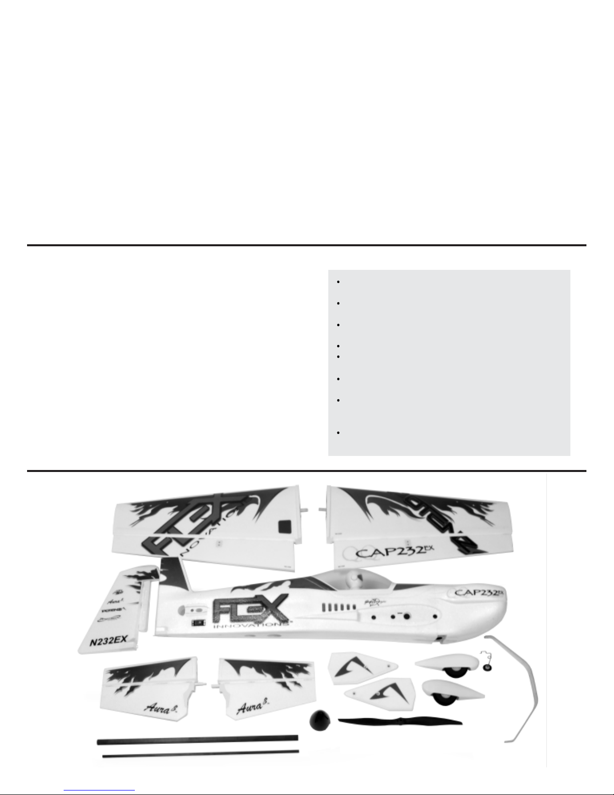
TABLE OF CONTENTS
Introduction
Box Contents
Specifications
Completion Items
Battery Charging Guidelines
Special Language Definitions
Important Information Regarding Warranty
Safety Warnings and Precautions
Low Voltage Cutoff
Rudder Installation
Tailwheel Installation
Main Landing Gear Installation
Transmitter Setup
Aura 8 AFCS
Receiver Installation/Servo Connections
Connecting a Battery/Arming the ESC
LED Controller Connections (Night Version Only)
..........................................................................
.......................................................................
......................................................................
................................................................
...............................................
..............................................
.........................
.......................................
..............................................................
..............................................................
...........................................................
............................................
................................................................
........................................................................
.............................
................................
...............
2
2
3
3
3
4
4
4
4
5
5
6, 7
8
8
9, 10
11
11
INTRODUCTION
The perfect "next step" aerobat to follow the QQ 300 or Mamba 10!
Masterfully scaled from the iconic Cap 232EX, World Champion
Quique Somenzini designed the QQ Cap 232EX to create an
experience never seen before. Optimized aerodynamics combined
with the Aura 8 revive the Cap flying performance to the highest Flex
Innovations standards. Carbon fiber is molded throughout the fuselage
and wings, and a plywood subframe secures the power system and
landing gear ensuring the airframe is lightweight, yet rigid. The QQ
Cap 232EX offers astonishing rock-solid, stable 3D aerobatic
capability, along with smooth, predictable precision flying.
Flex Innovations has tuned and matched both the air frame and power
plant offering incredible performance and flight times. The QQ Cap
232EX comes with the pre-installed and factory pre-programmed Aura
8 AFCS to offer the most enjoyable flying experience.
For the latest updates, features, addendums and more, before
assembly, please visit:
http://wiki.flexinnovations.com/wiki/QQCap232EX
Linkage and Horizontal Stabilizer Installation
Main Wing and SFG Installation
Transmitter Control Direction Test
Flight Controller Sensing Direction Test
Propeller and Spinner Installation
Battery Installation
Center of Gravity
Pre-Flight Checks
Flying your QQ Cap 232EX
Advanced QQ Cap 232EX Aura Configuration
Airframe Repairs
Replacing Servos
Servicing the Power System
Removing/Installing the Pilot
Aircraft Troubleshooting Guide
Limited Warranty
AMA Safety Code
Pre-installed and custom-tuned Aura 8 Advanced
Flight Control System
No control coupling, something never seen on a Cap
232!
(4) Potenza DS33HV, high-voltage, metal-gear, highspeed servos.
Light wing loading for easy handling
7-12 minute flight times depending on battery choice
and throttle management
Large choice of batteries - 2800-5200mAh on 5S or
6S Li-Po
3.5mm 6061 aluminum landing gear mounted directly
to the plywood sub-frame, and supported with "L"
aluminum brackets.
Potenza 60 3D motor for amazing power and
efficiency
.......................................................................
..........................................................................
........................................................................
..........................................................................
.........................................................................
.........................................................................
........................................................................
..................................................
...............................................
................................................
.........................................................
.......................................................
.......................................................
....................................................
................................
......................................
............................
12, 13
14
15
16
17
18
19
19
20
21
22
22
23
23
24
25
26
BOX CONTENTS
2
COMPLETION ITEMS
Potenza 60-3D 500 Kv
Brushless Outrunner Motor
(FPZM10603D)
HobbyWing SkyWalker 80A
ESC with 7.4V/8A External BEC
(HWBQ8012EBHV)
Potenza DS33HV Digital Servos
(FPZDS33HV)
Aura 8 Advanced Flight Control
System (FPZAURA08ZZC232)
16 x 6 Electric SR Propeller
(FPMP1606E)
2800-5200mAh 6S 22.2V 30C+ Li-Po
(FPZB35006S40)
2800-5200mAh 5S 22.2V 30C+ Li-Po
(FPZB52005S40)
6+ Channel Computer Transmitter
NEEDED TO
COMPLETE
INSTALLED!
INSTALLED!
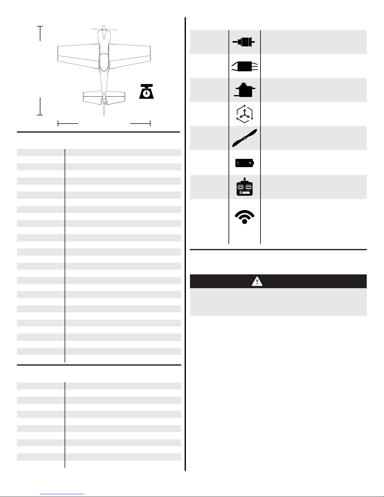
SPECIFICATIONS
60.2 in. (1531mm)
58.2 in. (1479mm)
Standard: 6.2lb (2.81kg)
RTF with 6S 3500mAh ba�ery installed
792 sq. in.
(51 sq. dm.)
BATTERY CHARGING GUIDELINES
The assembly of the QQ Cap 232EX can be accomplished i
REPLACEMENT PARTS
FPM337001
FPM337002R
FPM337002L
FPM337003
FPM337004
FPM337005
FPM337006
FPM337007
FPM337008
FPM337009
FPM337010
FPM337017
FPM337011
FPM337012
FPM337013
FPM337014
FPM337015
FPM337016
FPM338001
FPM338002R
FPM338002L
FPZM10603D
FPZM10603D1
FPZM10603D2
FPZM10603D3
FPZA1016
HWBQ8012EBHV
FPZDS33HV1
FPZDS33HV2
FPZA1017
Fuselage
Right Wing Panel
Left Wing Panel
Tail Set
Canopy Hatch w/Pilot
Aluminum Landing Gear
Wheel Pant Set w/Wheels, Axles & Tail Gear
Wing and Stab Tube Joiner Set
Pushrod Set
Yellow/Orange Decal Set
Blue/Purple Decal Set
Spinner
Hardware Package
Pilot
SFG Set
Ball Link Set (5)
LED Strip L&R Stabilizer
Main (2) & Tail Wheel Collar Set
Fuselage w/Night LED
Right Wing w/Night LED
Left Wing w/Night LED
60 3D 500kv BL Motor
60 3D Bolt-On Prop Adapter
60 3D Aluminum X-Mount
60 3D Motor Shaft
Advanced R/C LED Controller (6S)
Skywalker 80A ESC w/External 7.4V-8A BEC
DS33 HV MG Mini Digital Servo 62mm Wire
DS33 HV MG Mini Digital Servo 35mm Wire
1.5-inch Plastic Servo Arm (2)
OPTIONAL ACCESSORIES
FPZAU01
FPZA1010
FPZB13003S25
FPZB13003S40
FPZB52005S40
FPZB35006S40
FPZB42006S40
FPZB52006S40
FPZC80
FTVHWBQ2006
SPMAR8010T
SPM9645
Potenza 3pc. Male-Male Servo Connectors
Potenza Digital Battery Analyzer
Potenza 3S 1300mAh 20C Li-Po (for LEDs)
Potenza 3S 1300mAh 40C Li-Po (for LEDs)
Potenza 5S 5200mAh 40C Li-Po
Potenza 6S 3500mAh 40C Li-Po
Potenza 6S 4200mAh 40C Li-Po
Potenza 6S 5200mAh 40C Li-Po
Potenza C-80 80W Multi Chemistry Charger
Hobbywing ESC Programming Card
Spektrum AR8010T DSMX Receiver
Spektrum DSMX Remote Receiver
(Recomended
SPM Receiver)
INSTALLED!
INSTALLED!
INCLUDED!
NEEDED TO
COMPLETE
NEEDED TO
COMPLETE
Receiver
FOLLOW ALL INSTRUCTIONS PROVIDED BY YOUR
BATTERY AND CHARGER MANUFACTURER.
FAILURE TO COMPLY CAN RESULT IN FIRE.
less than one hour. Prior to assembling the airplane, it is
advisable to charge your battery so that you are ready to begin
setup upon completion of the assembly of your model.
We recommend the use of an advanced Li-Po balancing
charger, such as our Potenza C80 Multi Chemistry Touch
Screen AC/DC balancing charger for your batteries to get the
maximum performance and lifespan.
Our airplanes are designed around our Potenza Li-Po batteries,
and we recommend the Potenza 6S 3500mAh 40C Li-Po for
advanced aerobatics, or the Potenza 5S 5200mAh 40C Li-Po
for sport aerobatics based on our extensive testing and
development. These batteries feature an EC5 connector, so no
soldering is required for use in your QQ Cap 232 EX.
All are available at www.flexinnovations.com
Spektrum Remote Receivers (2),
Spektrum SRXL, Futaba S.Bus,
Hitec S.Bus, Graupner SumD, JR
XBus Mode B, Jeti UDI 12,
5+ Channel Receiver (any brand)
WARNING
n
3

SPECIAL LANGUAGE DEFINITIONS
WARNING
AGES 14+
NOTICE:
CAUTION:
WARNING:
Procedures, which if not properly followed, create a possibility of physical
property damage AND a little or no possibility of injury.
Procedures, which if not properly followed, create the probability of physical
property damage AND a possibility of serious injury.
Procedures, which if not properly followed, create the probability of property
damage, collateral damage, and serious injury OR create a high probability of
serious injury.
Read the ENTIRE instruction manual to become familiar with the features of the
product before operating. Failure to assemble or operate the product correctly can
result in damage to the product, personal property, and cause serious or fatal injury.
All instructions, warranties and other collateral documents are subject to change at
the sole discretion of Flex Innovations, Inc. For up-to-date product literature, please
visit our website at www.flexinnovations.com and click on the QQ Cap 232EX and
Aura 8 product pages.
This product is not intended for
use by children under 14 years
without direct adult supervision.
IMPORTANT INFORMATION REGARDING WARRANTY
SAFETY WARNINGS AND PRECAUTIONS
Please read our Warranty and Liability Limitations section before building this product. If you as the Purchaser or user are not
prepared to accept the liability associated with the use of this Product, you are advised to return this product immediately in
new and unused condition to the place of purchase.
LOW VOLTAGE CUTOFF
Protect yourself and others by following these basic safety guidelines.
1. This manual contains instructions for safety, operation and maintenance. It is essential to read and follow all the
instructions and warnings in the manual, prior to assembly, setup or use, in order to operate correctly and avoid damage or
serious injury.
2. This model is not a toy, rather it is a sophisticated hobby product and must be operated with caution and common sense.
This product requires some basic mechanical ability. Failure to operate this product in a safe and responsible manner could
result in injury or damage to the product or other property.
3. This model must be assembled according to these instructions. Do not alter or modify the model outside of these
instructions provided by Flex Innovations, Inc. as doing so may render it unsafe and/or unflyable. It is your responsibility to
ensure the airworthiness of the model.
4. Inspect and check operation of the model and all its components before every flight.
5. If you are not an experienced pilot or have not flown a high-performance model before, it is recommended that you seek
assistance from an experienced pilot in your R/C club for your first flights. If you're not a member of a club, the Academy of
Model Aeronautics (AMA) has information about clubs in your area whose membership includes experienced pilots.
6. Keep the propeller area clear from such items as loose clothing, jewelry, long hair, or tools as they can become entangled.
Keep your hands and body parts away from the propeller as injury can occur.
7. Never fly in visible moisture, or submerge the airplane or any of its electronic components in water. Permanent damage to
electronic components may occur, or corrosion of components may lead to intermittent failures.
Li-Po batteries have a nominal (rated) voltage of 3.7V per cell, and fully charged, reach 4.2V per cell. Batteries are designed
to be discharged below the nominal voltage, however, if they are discharged below 3.0V per cell, damage will occur and the
pack will lose capacity. For best long term battery life, set a timer and land after a time that leaves approximately 15% of the
battery's capacity remaining.
Low voltage cutoff is a feature that is built into the Hobby Wing SkyWalker 80A ESC that is designed to protect the connected
battery from being discharged too far and causing permanent damage to the cells. Circuitry within the ESC will automatically
detect when the input voltage from the battery pack reaches below 3.15V per cell (average) and will remove power to the
motor, but still deliver power to the servos so that a safe landing may be made. If the motor begins to lose power rapidly
during flight, the LVC has sensed that the total voltage of the pack has dropped blow 3.15V per cell average, and the airplane
should be landed immediately.
4
The following terms are used throughout the product literature to indicate various levels of potential harm when operating this product:
ATTENTION
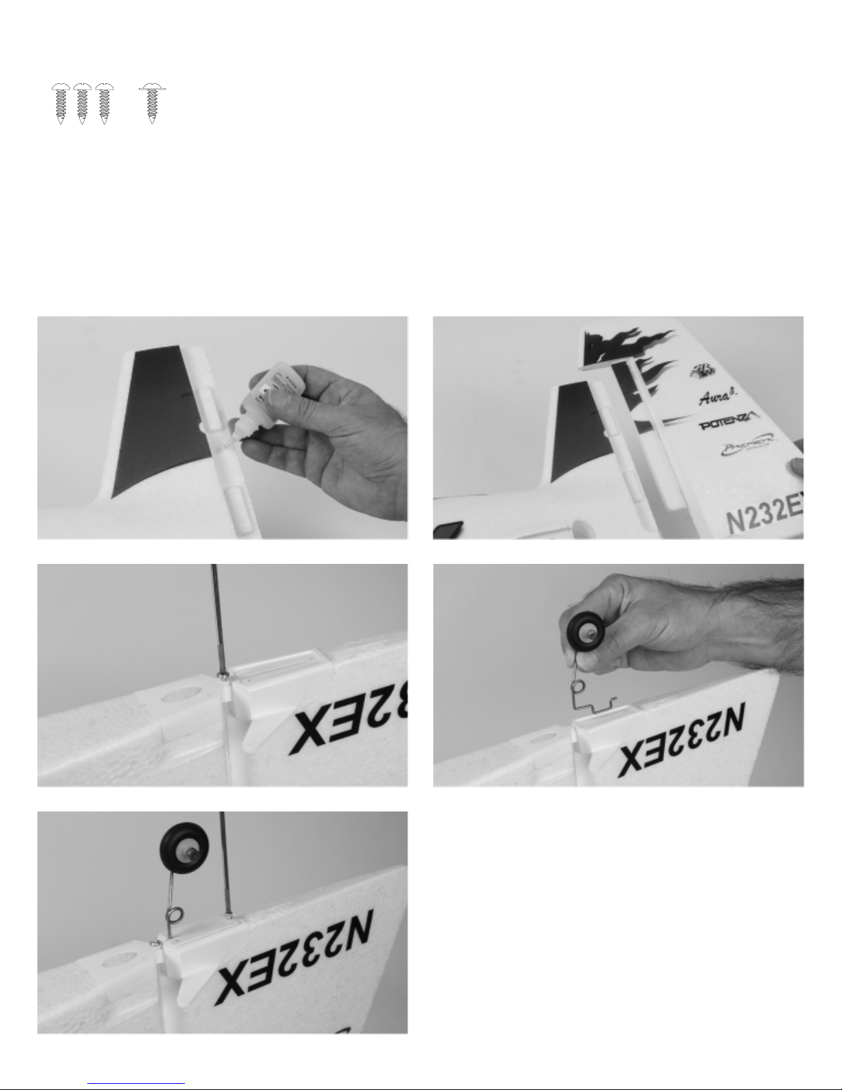
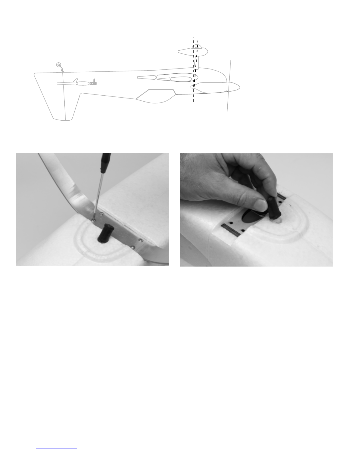
RUDDER INSTALLATION
Required Tools and Fasteners:
1.
The rudder comes pre-hinged to a small section of vertical fin. Test fit the rudder and fin section onto the fuselage and remove it
from the fuselage once fit is confirmed.
2.
Lay the fuselage on its side, and using medium CA or epoxy (foam-safe is not required), apply an adequate amount to the
fuselage. Press the rudder and vertical fin section into the fuselage, being sure to wipe away any excess glue.
3.
Secure the lower plastic hinge in place by threading an M3x10 phillips washer head self-tapping screw through the bottom of the
plastic hinge in the fuselage. Do not fully tighten, as you can cause the rudder to bind. A small amount of play is needed here.
4.
Allow time for the CA to dry, and once dry, check for proper rudder movement. Be sure the rudder moves freely with little to no
binding.
5.
Press the tailwheel wire into the plate on the bottom of the rudder. Be sure to orient the tailwheel such that it angles aft as it moves
away from the fuselage. Lay the tailwheel plate over the wire, and secure it in place with three M3x10 phillips head self-tapping
screws.
Medium CA (or 5-15 minute epoxy)
#1 Phillips Screwdriver
3 - M3x10 Phillips Head Self-Tapping Screw
1 - M3x10 Phillips Washer Head Self-Tapping Screw
5
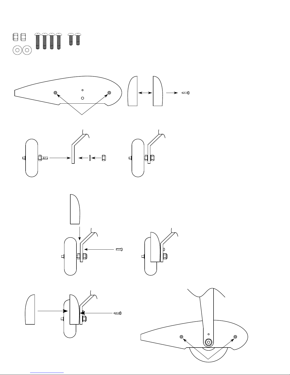
MAIN LANDING GEAR INSTALLATION
Required Tools and Fasteners:
1.
Locate the landing gear, axle assemblies, wheel pants, and M4 nuts and washers.
2.
Use a Phillips screwdriver to remove the M3x12 self-tapping screws from the wheel pants, and separate the wheel pant halves from
one another.
3.
Remove the M4 nut and washer from the axle assembly (if required). Slide the axle through the landing gear, and place an M4 washer
over the exposed threads of the axle. Secure the axle in place using an M4 lock nut, and two 7mm wrenches. Tighten fully.
7mm Wrench (2)
#1 Phillips Screwdriver
M4 Washer (2)
M4 Lock Nut (2)
M3x10 Phillips Head Machine Screw (2)
M3x15 Phillips Head Machine Screw (4)
Axle/Wheel Assembly
Landing Gear
Wheel Pants
Blue Thread Lock
Medium CA
x2
4.
Install the inside-half of the wheel pant to the landing gear using an M3x10 Phillips head machine screw, and blue thread lock. If you
wish to leave the wheel pants off of the aircraft, you can skip this step as well as step 5.
5.
Re-install the outside half of the wheel pant to the inner half using the M3x12 self-tapping screws removed in step 2.
x2
6
MAIN LANDING GEAR INSTALLATION (CONTINUED)
With the fuselage inverted on your work space, place the landing gear on the landing gear mount, being sure to orient the landing gear
6.
so that it sweeps forward as it moves away from the fuselage.
7.
Apply a small amount of blue thread lock to each of the 4 M3x15 phillips head screws. Insert them through the landing gear, and tighten
them into the fuselage using a Phillips screwdriver.
8.
Use medium CA to glue the exhaust detail in place.
7
WARNING
DO NOT ATTEMPT RADIO SETUP WITH PROPELLER INSTALLED. INADVERTENT POWER UP COULD CAUSE
DEATH OR SERIOUS INJURY.
TRANSMITTER SETUP
Start with a freshly reset new model memory in your transmitter. Make
ONLY the changes shown in the Transmitter Configuration Guide.
The Aura 8 in the QQ Cap 232EX defaults to 3 flight modes that are
switched via CH5/Gear in your transmitter. You may need to reassign
CH5/Gear to a 3-position switch.
The LEDs in the Night QQ Cap 232EX are switchable on/off via CH6/
Aux 1 in your transmitter. You may need to reassign CH6/Aux 1 to a 2position switch.
Consult your transmitter manual if you have questions on how to
change the switch or channel assignments.
The Aura comes pre-programmed with dual rates and expos
specifically designed for the QQ Cap 232EX. For large (greater than
5%) changes in expo or dual rates, it is highly recommended to reset all
expos and rates to default in the transmitter, and tune through the Aura
Config Tool.
The Aura Config Tool is free to dowload, and can be used on any
Windows-based PC or tablet. Download at:
www.flexinnovations.com/AuraConfigTool
AURA 8 AFCS
The Aura 8 advanced flight control system installed in your QQ Cap
232EX is a giant leap forward in aircraft flight control system
technology. Compatible with virtually every receiver on the market
today, the Aura features special configuration for DSM systems via
remote receiver connection(s), and serial data connection for Futaba or
Hitec S.Bus, Spektrum SRXL, Graupner HOTT (Sum D of 8), JR XBus
(Mode B), and Jeti UDI12 (standard) systems, as well as being
compatible with traditional receivers via PWM servo connections.
The Aura 8 advanced flight control system in your QQ Cap 232EX has
been pre-tuned for ease of use, eliminating many hours of tedious
setup. For the latest Aura features, programs, transmitter downloads,
and instructions, please visit wiki.flexinnovations.com/wiki/Aura
The Aura is programmable through any Windows based PC or tablet.
All dual rate, expo, travel, and assignable mode programs are adjusted
inside the Aura through the PC application. An assignable master gain
that is OFF by default can be enabled by the Aura application. If
desired, assign CH 8/AUX 3 on a proportional dial or slider.
By default, CH5/Gear is used to select the 3 flight modes by 3 position
transmitter switch. CH6/Aux 1 is used to select the on/off position of the
LED controller by 2 position transmitter switch (night version only).
TRANSMITTER CONFIGURATION GUIDE
Wing/Tail Type
End Points
(Travel Adjust
or ATV)
Reversing
Sub Trim
Trim Levers
CH. 5 (Gear)
CH. 6 (Aux1)
Timer
1.
Note: JR Mode B users set Throttle, Aileron, Elevator, Rudder and Gear travels to 88%.
2.
Throttle direction depends on transmitter brand and receiver connection type. Leave at
defaults to start, and reverse as needed.
3.
This is only required to switch the LEDs on/off via the transmitter. If the LED controller is
unplugged from the receiver or Aura 8, the lights default in the ON position when
powered.
4.
The QQ Cap 232 EX can fly anywhere between 5 and 7 minutes (w/6S 3500mAh Li-Po)
depending on flying style.
Works conveniently with all major radio systems
Accepts signals from DSM Remote Receiver(s), Spektrum
SRXL, Futaba S.Bus, Graupner Hott (Sum D of 8), JR XBus
(Mode B), Jeti UDI12 (standard), Hitec S.Bus, PPM Stream, or
any brand of receiver via male to male servo connectors
Expertly tuned and ready to use
USB port allows loading model configurations, user
programming, and firmware updates (cable included)
Flexible and extensive programming through Windows-based
PC or tablet
3+ flight modes allow precise or aggressive settings to be
selected in flight
3-axis gyro utilized in QQ Cap 232EX programming
Powerful 32-bit processor and multi-axis sensor for future
updates.
Visit wiki.flexinnovations.com/wiki/Aura for the latest
Aura-related product information and tips for your
Normal - 1 Aileron, 1 Elevator, 1 Rudder
Aileron/Elevator/Rudder
1
Throttle/Gear (Ch.5)
Ail/Ele/Rudder set to Normal
Thro depends on receiver connection type
Verify at zero, sub-trim not allowed
Verify at zero
Assigned to a 3-position switch
Assigned to a 2-position switch (for LEDs)
4
Set to 5:00 for initial flights
particular radio brand.
125%
100%
2
3
Description of Pre-Loaded Aura Flight Modes (FM)
Mode 1 (Gyro Off): Rates are set for general flight (same as
Sport Mode). Exponential is tuned for comfortable flight.
Mode 2 (Sport Mode): Gains are moderate and tuned for
comfortable feel/best performance for precision aerobatics.
Expo is tuned for comfortable flight.
Mode 3 (3D Mode): Gains are highest and tuned for 3D
aerobatics. Rates are set to highest. Exponential is tuned for
comfortable flight.
NOTE - Rudder stick movement will also move elevator.
This is NORMAL, and is the pre-programmed knife edge
correction mixing in the Aura 8.
Each of the modes has been tuned by our team to offer a solid
start. Because tastes in control feel are unique, if changes in
rates and expo are needed, adjustments should be made
through the Aura.
Changes in gain value can only be made through the Aura.
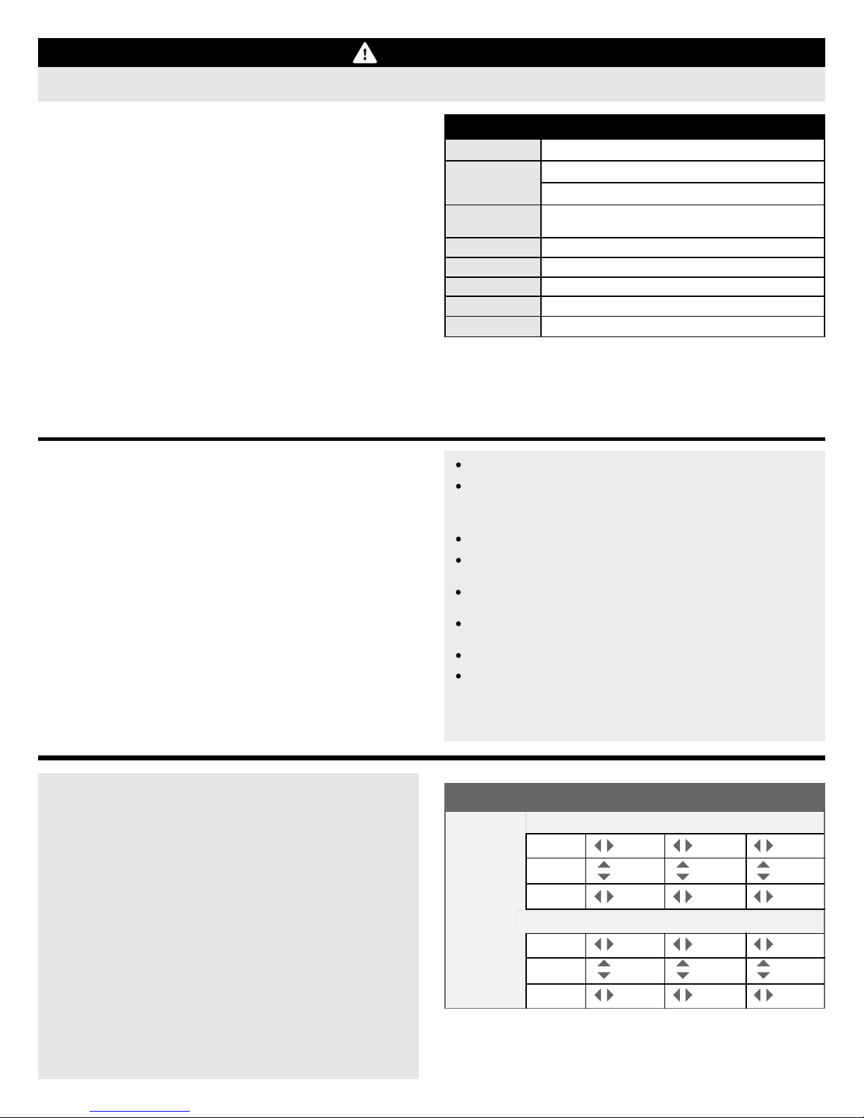
REFERENCE ONLY: Aura Settings
Mode 1
Aura 8
Rate Setup
Aileron
Elevator
Rudder
50%
20%
60%
Mode 1
Aileron
Aura 8
Expo Setup
Elevator
Rudder
DO NOT PROGRAM THESE VALUES INTO YOUR TRANSMITTER!
The shown Aura 8 settings are pre-configued and the unit is ready to use.
The chart shown is for informational purposes only. No additional action is
required to fly the airplane.
42%
35%
27%
Mode 2 Mode 3
50%
20%
60%
100%
100%
107%
Mode 2 Mode 3
15%
14%
0%
45%
50%
35%
8
 Loading...