

Page 1
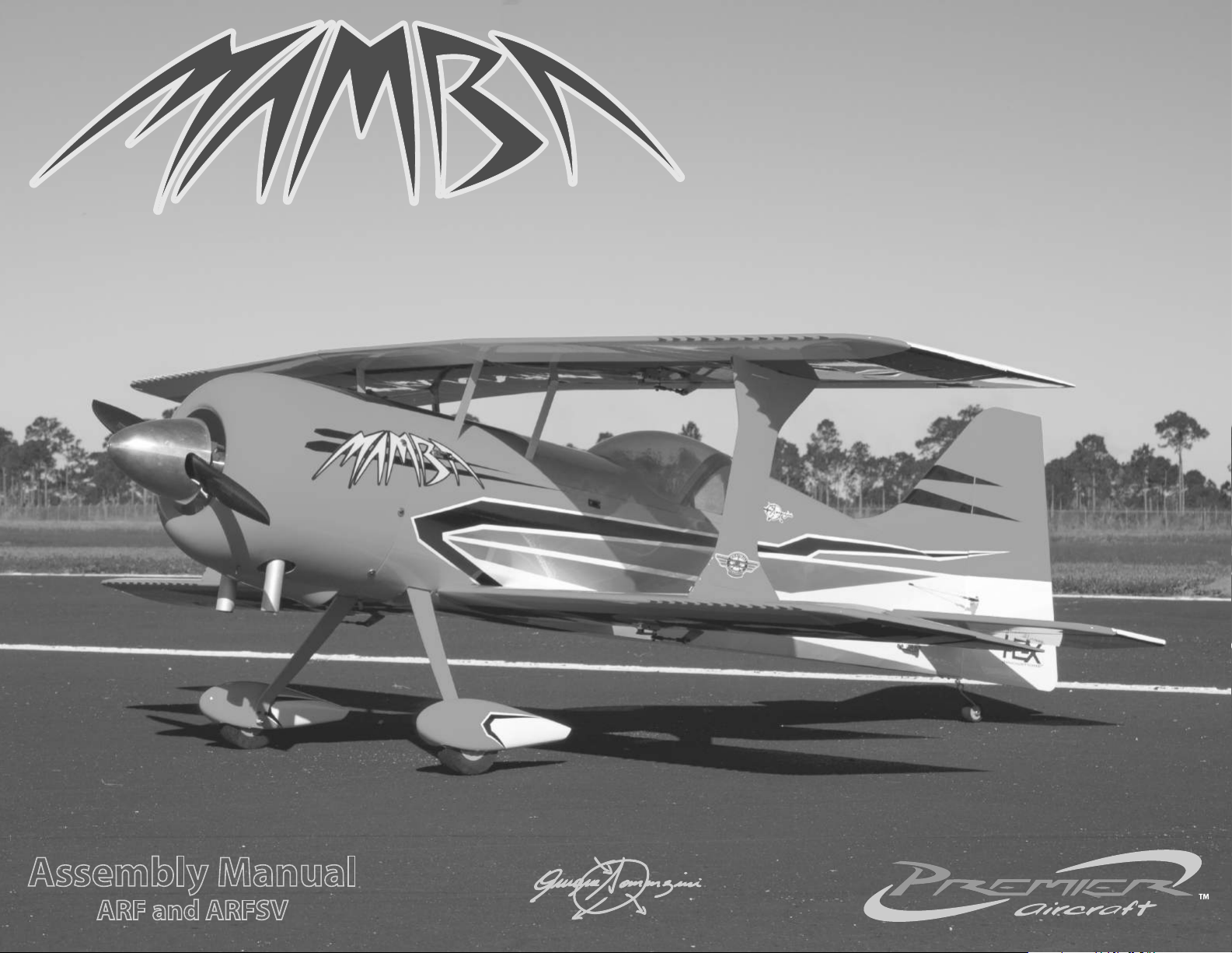
Assembly Manual
ARF and ARFSV
Page 2
INTRODUCTION
Congratulaons on the selecon of your new Premier Aircra Mamba 70cc.
Designed by Quique Somenzini, Flex Innovaons co-founder and world
aerobac champion, this airplane is designed to excel in both precision and 3D
aerobacs. Strict aenon to structural and aerodynamic design details make
the Mamba a very special airplane that's sure to give you a lot of sasfacon.
Flex Innovaons, Inc. and Premier Aircra thank you for your purchase...enjoy
it!
USING THIS MANUAL
This manual is divided into secons to make the assembly of the airplane easier
to follow. Note the boxes ( ) next to each step to help you keep track of the
steps that have been completed.
SPECIAL LANGUAGE DEFINITIONS
The following terms are used throughout the product literature to indicate
various levels of potenal harm when operang the product.
NOTICE:
CAUTION:
WARNING:
Procedures, which if not properly followed, create a possibility of
physical property damage AND a lile or no possibility of injury.
Procedures, which if not properly followed, create a probability of
physical property damage AND a possibility of serious injury.
Procedures, which if not properly followed, create the probability
of property damage, collateral damage, and serious injury OR
create a high probability of serious injury.
ATTENTION
Read the ENTIRE instrucon manual to become familiar with the features of
the product before operang. Failure to assemble or operate the product
correctly can result in damage to the product, personal property, and cause
serious or fatal injury.
All instrucons, warranes and other collateral documents are subject to
change at the sole discreon of Flex Innovaons, Inc. For up-to-date product
literature, please visit our website at www.exinnovaons.com and click on
the support tab for this product.
IMPORTANT INFORMATION REGARDING WARRANTY
Please read our Warranty and Liability secon before building this product. If
you as the Purchaser or user are not prepared to accept the liability associated
with the use of this product, you are advised to return this product
immediately in new and unused condion to the place of purchase
SAFETY WARNINGS AND PRECAUTIONS
Protect yourself and others by following these basic safety guidelines.
This manual contains instrucons for safety, operaon and maintenance. It
1.
is essenal to read and follow all the instrucons and warnings in the
manual, prior to assembly, setup or use, in order to operate correctly and
avoid damage or serious injury.
In some cases, the wrien instrucons may dier slightly from the photos.
2.
In those instances, the wrien instrucons should be considered correct.
This model is not a toy, rather it is a sophiscated hobby product and must
3.
be operated with cauon and common sense. This product requires some
basic mechanical ability. Failure to operate this product in a safe and
responsible manner could result in injury, or damage to the product, or
other property.
This model must be assembled according to these instrucons. Do not alter
4.
or modify the model outside of these instrucons provided by Flex
Innovaons, Inc, as doing so may render it unsafe and/or unyable. You
must take me to build straight, true and strong. It is your responsibility to
ensure the air worthiness of this product.
Use only compable, appropriate components for the nal assembly of this
5.
model. Ensure that the radio system is in funconal condion, that the
engine is appropriately sized for the model, and that all other components
are appropriate for use in this model as specied in this instrucon manual.
All components must be installed correctly such that they operate correctly
both on the ground and in the air.
Inspect and check operaon of the model and all its components before
6.
every ight.
7.
If you are not an experienced pilot, or have not own a high-performance
model before, it is recommended that you seek assistance from an
experienced pilot in your R/C club for your rst ights. If you're not a
member of a club, the Academy of Model Aeronaucs (AMA) has
informaon about clubs in your area whose membership includes
experienced pilots.
!
WARNING
This product is not intended for use by children under 14 years without direct
adult supervision.
8.
Keep the propeller area clear from such items as loose clothing, jewelry,
long hair, or tools, as they can become entangled. Keep your hands and
body parts away from the propeller as injury can occur.
1
Page 3
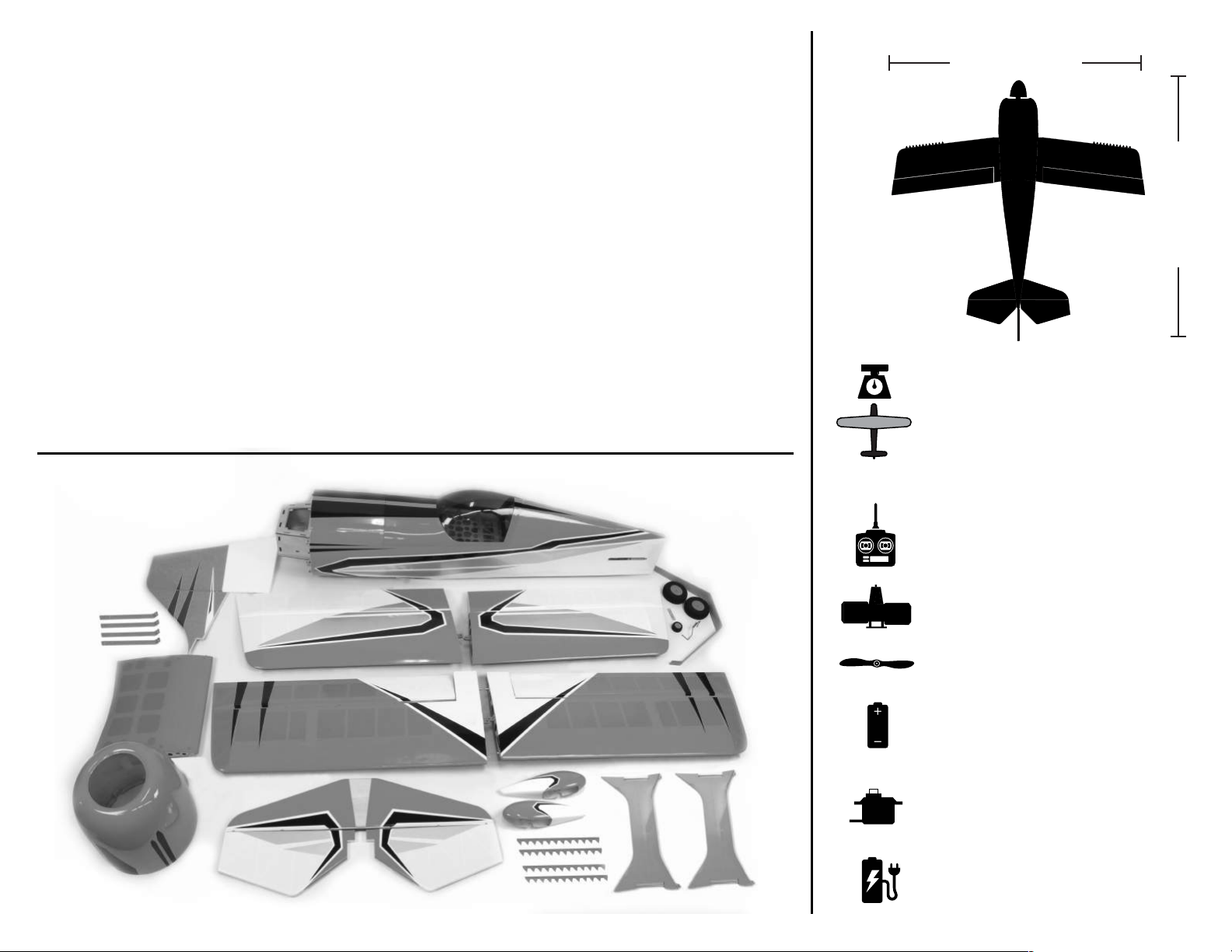
TABLE OF CONTENTS
50-70cc Gasoline (Petrol) Engine
Falcon Carbon Fiber 24x9
See your engine manufacturer's manual for
recommendaons on your parcular engine.
(6) High Torque Digital Servos
Introducon .......................................................
Using this Manual ..............................................
Special Language Denions .............................
Warranty Noce .................................................
Safety Warnings and Precauons ......................
Kit Contents .......................................................
Specicaons .....................................................
Compleon Items ..............................................
Recommended Compleon Items .....................
Replacement Parts Lisng ..................................
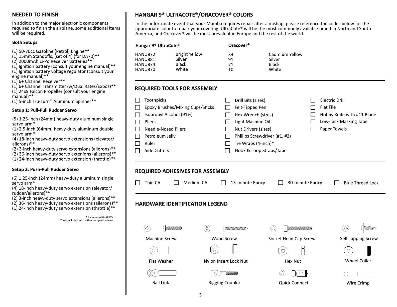
Hangar 9 UltraCote/Oracover Colors ...............
Required Tools ...................................................
Required Adhesives ...........................................
Hardware Legend ...............................................
Assembly Symbol Legend ..................................
Before Starng Assembly ...................................
Aileron and Control Horn Installaon ................
Interplane Strut Block Installaon .....................
Aileron Servo/Linkage Installaon .....................
Elevator/Rudder Servo Installaon ....................
Elevator/Rudder Control Horn Installaon ........
Horizontal Stab/Elevator Installaon .................
1
1
1
1
1
2
2
2
3
3
3
3
3
3
4
4
4-6
6-7
7-8
11-12
12-13
14-15
Vercal/Rudder/Tail Wheel Installaon ...........
Rudder/Elevator Final Linkage Installaon ......
Landing Gear Installaon .................................
Fuel Tank Assembly ..........................................
Engine/Throle Servo Installaon ...................
Ignion Installaon ..........................................
Exhaust Installaon ..........................................
Fuel Tank Installaon ........................................
Cowling Installaon ..........................................
Center Secon Installaon ...............................
Radio Gear/Aura 8 Installaon .........................
Shark Teeth Installaon ....................................
Field Assembly ..................................................
Center of Gravity ..............................................
Decal Installaon ..............................................
Aura 8 Setup .....................................................
Radio Setup/Range Test/Before First Flight ......
Replacement/Oponal Parts ............................
Limited Warranty ..............................................
AMA Safety Code ..............................................
Building and Flying Notes .................................
16-19
19
20-21
21-23
21-28
28-29
29-31
31-32
33
34-35
35-36
37
38
39
40
41
42
43
44
45
46-47
77.2 in (1961mm)
19.0 lb (8.61kg)
*weight may vary due to producon
tolerances and gear selecon.
2070 sq. in (133.5 sq. dm.)
79.5 in (2020mm)
KIT CONTENTS
RECOMMENDED COMPLETION ITEMS
6+ channel transmier with
adjustable dual rates/mixing
Desert Aircra DA70
2 x 2000mAh Li-Po (Receiver)
1 x 2000mAh Li-Po (Ignion)
6 x Potenza DS41611BLHV-H
1 x Potenza DS19410TGHV
400+ oz/in (28.8+ kg/cm)
Potenza (FPZC0080)
Mul-Chemistry LiPo Balancing Charger
2
Page 4
Page 5
ASSEMBLY SYMBOL LEGEND
Mark
Test Fit
Fully Tighten
Clamp
Cut with
#11 Blade
Drill
Apply
Threadlocker
Use
Thin CA
Use
Medium CA
Use 5
Minute
Epoxy
Use 15
Minute
Epoxy
Use 30
Minute
Epoxy
Apply
Light Oil
Duplicate
Assembly
Ensure
Free
Rotaon
Mirror
Assembly
IMPORTANT BEFORE STARTING ASSEMBLY
Organizaon is key to building a successful, well-built, good-ying model. Please take a
few moments to follow these next few steps to ensure you are geng the most out of
your Mamba, and ensure that it will be in your stable for a long me to come.
1.
2.
4.
Remove all parts from their plasc bags, inventory all items and closely
examine all of the major airframe components for damage. If any items are
missing, or you nd damaged components, please contact customer support.
Use a covering iron with a covering sock on high heat to ghten the covering
as necessary, paying special aenon to the leading edges of the ying
surfaces, hinge lines and stabilizer and wing saddle areas. Apply slight pressure
over sheeted areas to thoroughly bond the covering to the wood. Use cauon
around seams to prevent inadvertently pulling them loose.
Gather all required components such as motor and radio equipment that will
be used to e
2.
AILERON HINGES AND AILERON CONTROL HORN INSTALLATION - ARF
Required Components
Main Wings (x4)
Control Horns (x8)
Required Adhesives
30-Minute Epoxy (Or other hinge-type glue)
Required Tools/Building Materials
Low-Tack Masking Tape
Petroleum Jelly
Epoxy Mixing Cups/Scks
Ailerons (x4)
Medium Grit Sand Paper
Isopropyl Alcohol (91%)
Paper Towels
Aileron Hinges (20)
Toothpicks (oponal)
HELPFUL HINT
In order to help prevent scratches on your new model, it is always best to work with
the parts on a so surface, like packing foam or felt.
1.
3.
Use thin CA to go over any important glue joints, such as the motor box,
rewall, servo mounng rails, and any other pre-assembled joints that may see
high stress during ight.
and bind this model program to the receiver that will be used in the airplane.
quip the airplane. Create a new radio program in your transmier
Test t the hinges into the ailerons, and then the hinges into the wings.
Ensure that the hinge pockets line up, and that the hinges move freely.
Prepare the aileron hinges by scung the area that will be inserted into the
wing or ying surface with medium grit sand paper. Be careful not to remove
too much material. Use isopropyl alchol, and a paper towel to remove any
excess debris that remains on the hinges.
4
Page 6
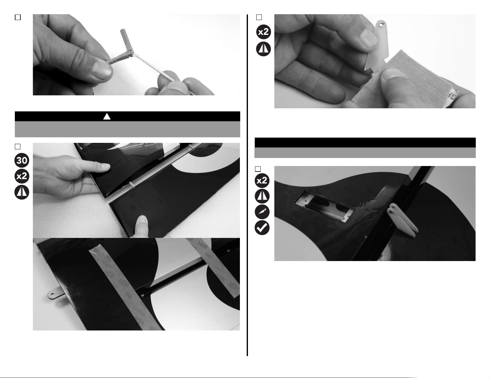
3.
WARNING
Using a toothpick or coon swab, apply a small amount of petroleum jelly to
the pivot of each hinge. Do not apply petroleum jelly to the enre hinge.
5.
!
WARNING
Petroleum jelly prevents glue adhesion. Do not apply petroleum jelly to the surface
areas of the hinge that require glue adhesion to the wing or surface.
4.
Prepare the aileron control horns by sanding the secon that extends into the
control surface with medium grit sand paper. Use isopropyl alcohol and a paper
towel to remove any excess debris from the control horn.
NOTICE
If not properly scued, glue may not adhere to the control horn, resulng in a failure.
6.
Locate the control horn slots in the ailerons, remove the covering from the slots
with a #11 hobby knife. Check the t of the control horns in the slots of the
ailerons. Make any adjustments necessary at this me.
Mix a sucient amount of 30-minute epoxy in a cup, and with a toothpick,
smear epoxy in the hinge pockets of the wing panel and aileron. Slowly and
carefully, insert each hinge into the wing panel. Parally remove and reinstall
the hinge to ensure that you've completely coated it with glue. Clean up any
excess epoxy with isopropyl alcohol, and tape the aileron in place to cure.
5
Page 7
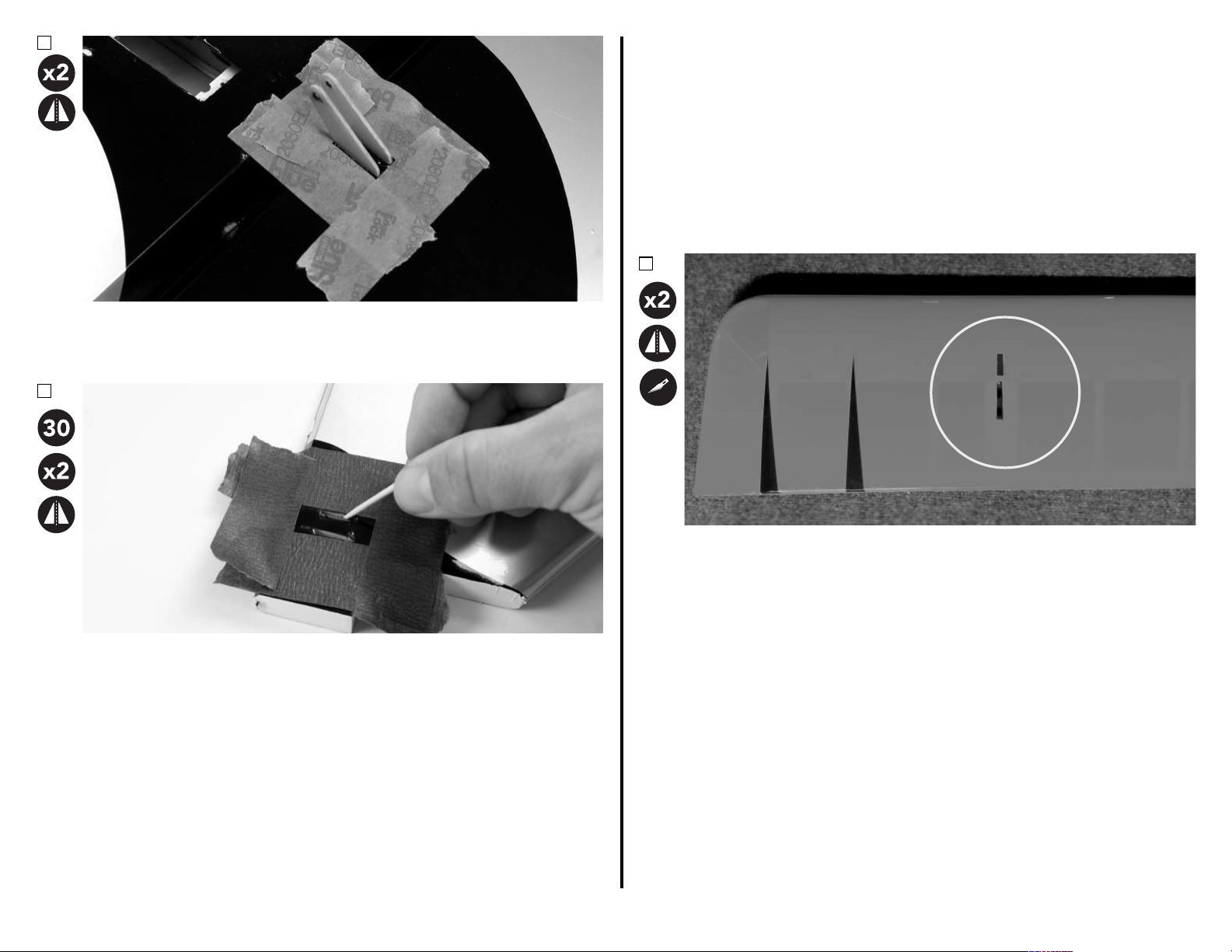
7.
Once sased with the t of the control horns, apply low-tack tape
approximately 1/32-inch (1mm) around the control horns. This will help keep
epoxy o of the surface of the ailerons. Once the tape has been applied,
remove the control horns.
8.
INTERPLANE STRUT BLOCK INSTALLATION - ARF
Required Components
Main Wing (x4)
Required Adhesives
30-Minute Epoxy
Required Tools/Building Materials
Covering Iron/Trim Iron
Low-Tack Tape
Interplane Strut Blocks (4)
Hobby Knife with #11 Blade
Isopropyl Alcohol
WARNING
1.
Paper Towels
Mix a sucient amount of 30-minute epoxy in a cup, and with a toothpick,
apply epoxy in the control horn slots in the aileron. Slowly and carefully,
insert each control into the aileron. Parally remove and reinstall the control
horn to ensure that you've completely coated it with glue. Before the epoxy
has fully cured, remove the tape, and clean up any excess epoxy with a paper
towel and isopropyl alcohol.
Locate the slots in the wing for the interplane strut block locaons. These are
located in the top of the boom wings, and the boom of the top wings.
Carefully cut and remove the covering from this slot, while leaving 1/8-inch
(3mm) extra covering over the inside of the slot. Cut the corners at a 45-degree
angle, and use a covering or trim iron to seal the covering down into the slot.
6
Page 8
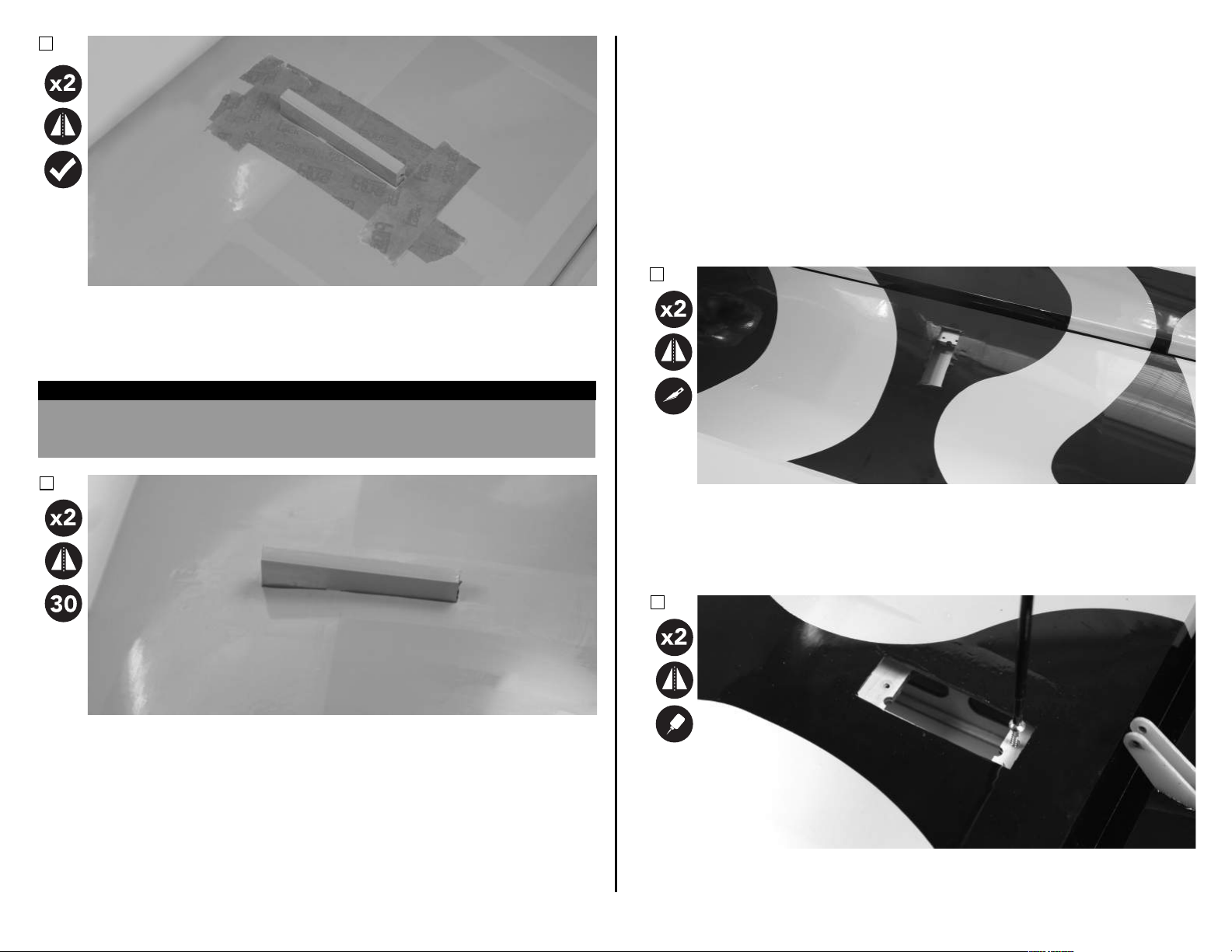
2.
Mix a sucient amount of 30-minute epoxy in a cup, and with a toothpick,
smear epoxy in the strut block pockets of the wing panel. Slowly and
carefully, insert each block into the wing panel. Parally remove and reinstall
the block to ensure that you've completely coated it with glue. Be sure to
rmly seat the block fully into the wing panel. Before the epoxy fully cures,
Use a #1 Phillips screwdriver to thread a servo mounng screw into each of th
Test t the blocks into the pockets. Be sure they t correctly and completely into
the pocket. Note that there are dierent blocks for the top wings, and dierent
blocks for the boom wings. They will not t in the opposite wing. Apply lowtack tape approximately 1/32-inch (1mm) away from the edges of the pocket in
the wing.
HELPFUL HINT
To conrm proper tment of the interplane struts and strut blocks, now is a good me
to test t the interplane struts to the blocks. Reference the "Field Assembly" secon
near the back of this manual for the interplane strut installaon guide.
3.
AILERON SERVO AND LINKAGE INSTALLATION - ARF
Required Components
Main Wing (x4)
Aileron Linkage (X4)
#4 Lock Nut (X8)
Required Adhesives
Thin CA
Required Tools/Building Materials
#1 Phillips Screwdriver
Thread or Shrink Tube
1.
Locate the aileron servo bays in the wings. Use a #11 hobby knife to remove
the covering, leaving approximately 1/8-inch (3mm) extra covering over the
inside of the pocket. Use a covering or trim iron to seal the covering into the
slot. Prepare the aileron servos by installing the rubber grommets and brass
eyelets. Secure a 6-inch (120mm) extension to the boom wing servos. No
extension is required for the top wing servos.
2.
Aileron Servo (x4)
Ball Links (X8)
#4 Washer (X16)
Blue Thread Lock
Ball Driver: 3/32
6-Inch (150mm) Extension (x2)
4-40 x 5/8-inch SHCS (X8)
Nut Driver: 1/4-inch
remove the low-tack tape, and clean up any excess epoxy with isopropyl
alcohol and a paper towel.
e
pre-cut holes in the servo mounng rails in the wing. Remove the screw, and
apply a small amount of thin CA to each of the holes to harden the threads cut
7
by the screw. Let the CA fully cure before moving forward.
Page 9
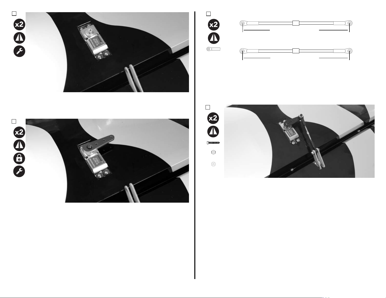
3.
Insert the aileron servo into the servo bay with the output sha towards the
leading edge of the wing. Be sure to route the servo lead out of the wing
before mounng the servo. Mount the servo to the wing using the screws
Center the servo using your radio system. Install a 1-1/4-inch (32mm) servo
arm onto the servo. Apply a very small drop of blue thread lock onto the
servo arm screw, and fully ghten the screw. Be sure to avoid geng thread
Using a pushrod of 2-inch (51mm) length, assemble the aileron linkages so
that the total length from center of ball to center of ball is approximately
2-13/16-inches (72mm) for the top wings, and 2-15/16-inches (75mm) for
the boom wings. Final length will be adjusted when centering the control
surface. Note that the ends of the aileron linkages use opposite direcon
threads.
6.
Aach the linkage to the servo arm. The order of components starng
AWAY from the wing is as follows:
- 4-40x5/8-inch Socket Head Cap Screw
- #4 Washer
5.
TOP WING
2-13/16-inches (72mm)
BOTTOM WING
provided with your servo.
4.
Ball Link (2)
2-15/16-inches (75mm)
**Note: Drawing not to scale
4-40x5/8 (2)
#4 (2)
#4 (4)
lock compound into the servo gears.
- Ball Link
- #4 Washer
- Servo Arm
- #4 Lock Nut
With the radio powered on, and the servo centered with the arm parallel to
the hinge line, adjust the linkage length so that the control surface is
centered. Aach the linkage to the control horn in the following order:
- 4-40x5/8-inch Socket Head Cap Screw
- #4 Washer
- Control Horn
- Ball Link
- Control Horn
- #4 Washer
8
Page 10
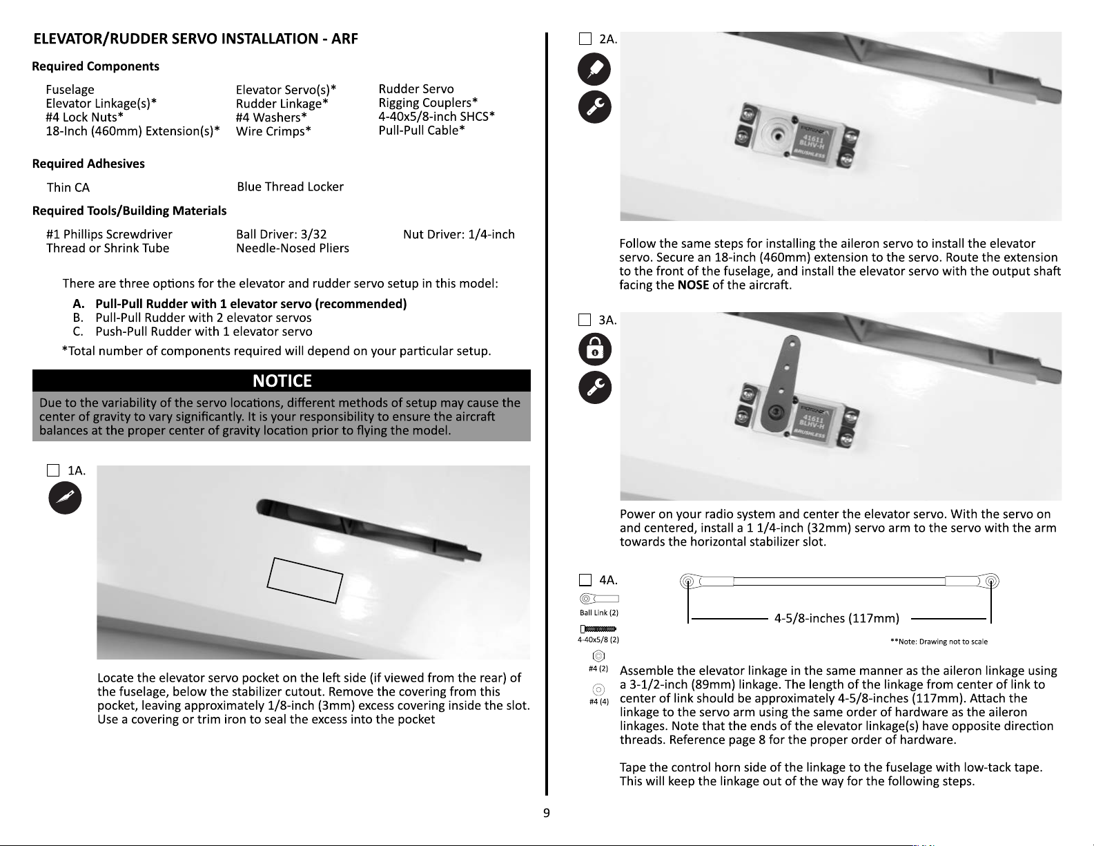
Page 11
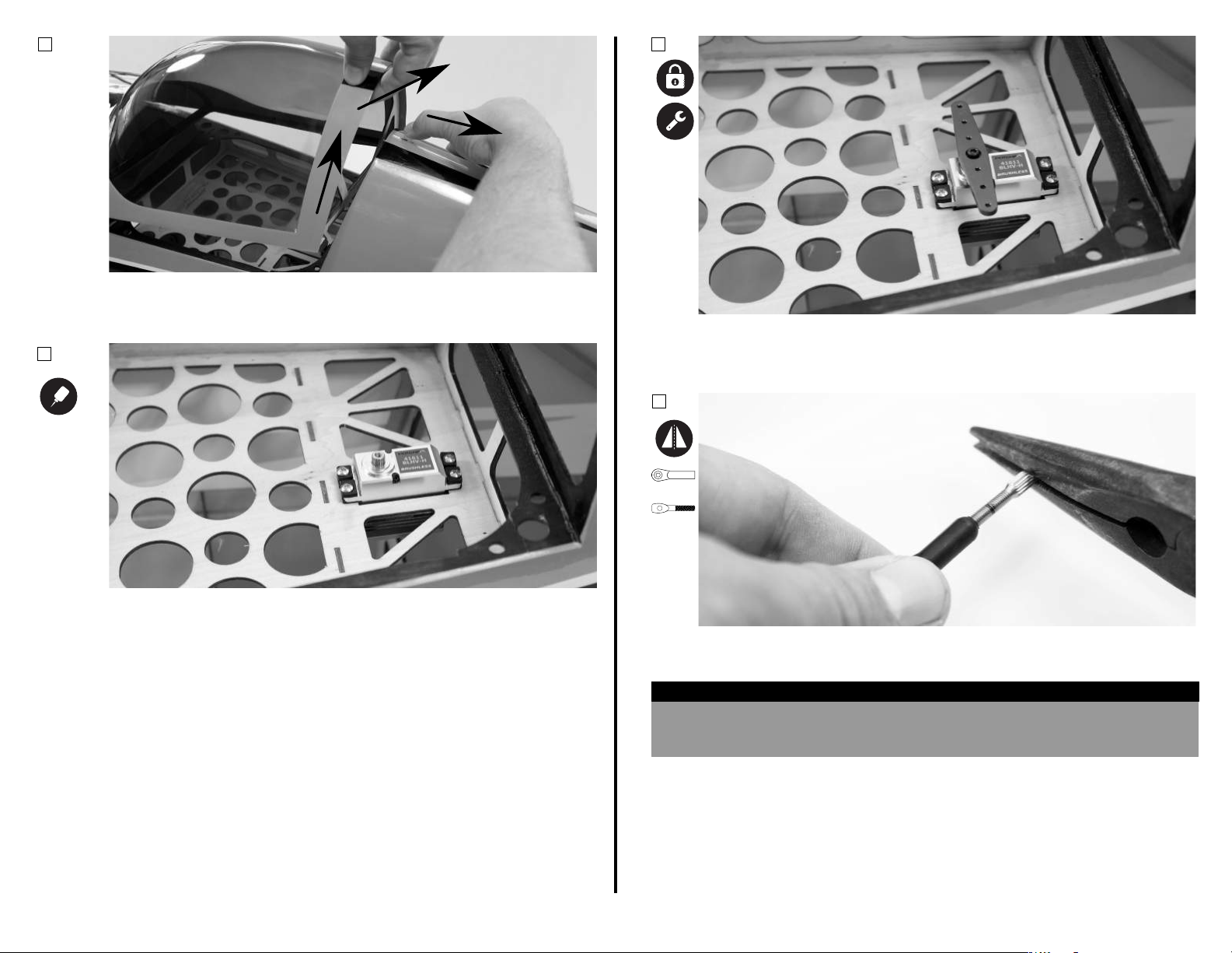
5A.
1.
2.
3.
6A.
Remove the canopy from the fuselage by pulling back on the latch, liing the
canopy in the rear, and sliding the canopy towards the rear as you li it away
from the fuselage.
7A.
Power on your radio system and center the rudder servo. With the servo
powered on and centered, install a 2-1/2-inch (64mm) double servo arm onto
the servo. Be sure the arm is perpindicular to the servo case.
8A.
Ball Link (1)
Install the rudder servo in the tray under the canopy area of the fuselage,
following the same procedure as the aileron servo installaon secon. If
using this servo locaon for the rudder, no servo extension is needed. The
servo should be installed with the output sha towards the front of the
aircra.
10
Rigging
Coupler (1)
Using pliers, thread a rigging coupler approximately halfway into a ball link.
HELPFUL HINT
You can take a ruler and felt-pped marker to mark the center of the threads on the
rigging coupler. Once the end of the ball link reaches the mark you made on the
threads, you know the rigging coupler has sucient thread depth into the ball link.
Page 12
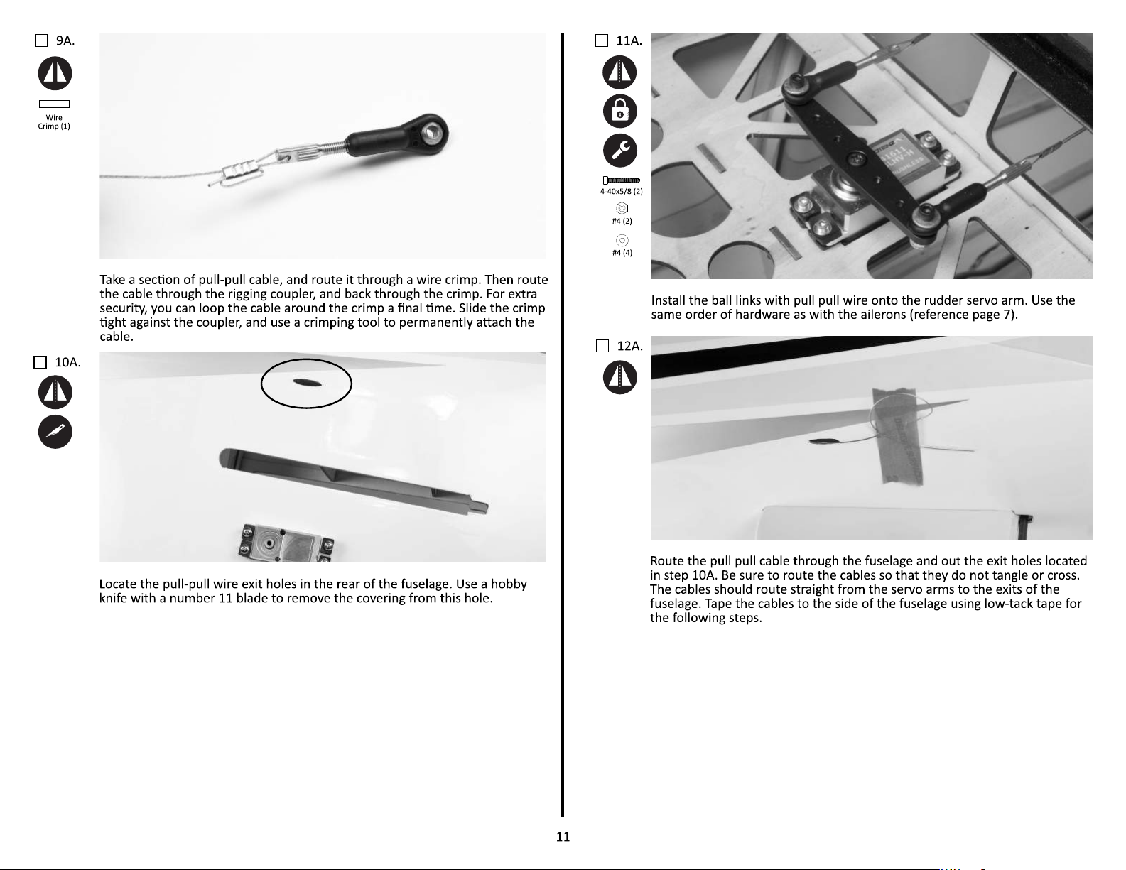
Page 13
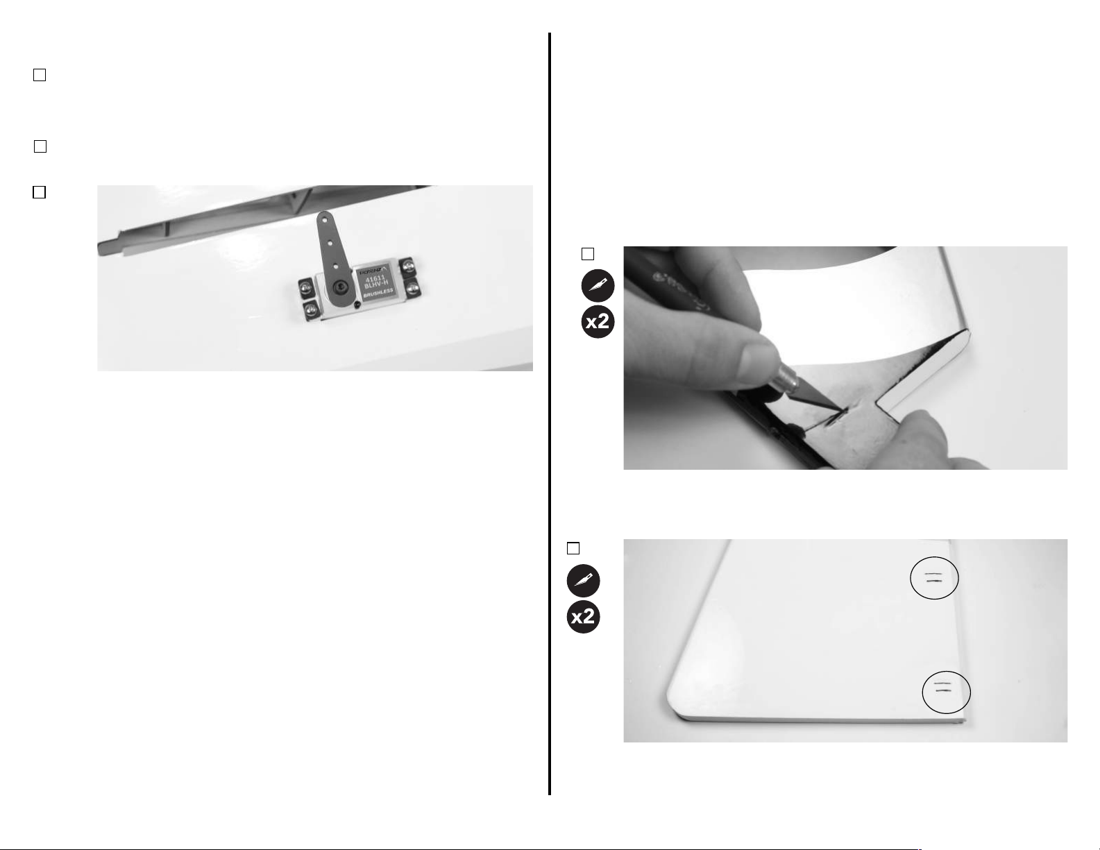
Dual Elevator Servos with Rudder Pull-Pull
2.
Pull-Pull Setup
Push-Pull Setup
ELEVATOR/RUDDER CONTROL HORN INSTALLATION - ARF
1B.
Standard Elevator Servo with Tail-Mounted Rudder Servo
1C.
2C.
Repeat steps 1A-4A for the right side of the fuselage.
Follow steps 1A-4A for the elevator servo. Repeat steps 1A-4A for the opposite
side of the fuselage. See details below:
Power on your radio system and center the rudder servo. With the servo on
and centered, install a 1 1/4-inch (32mm) servo arm onto the servo with the
arm towards the horizontal stabilizer slot.
Required Components
Rudder
Elevator Control Horns*
Required Adhesives
30-Minute Epoxy
Required Tools/Building Materials
Low-Tack Tape
*Number of parts required will vary depend on elevator setup type (dual versus single elevator)
1.
Elevator (X2)*
Isopropyl Alcohol
Rudder Control Horns
Paper Towels
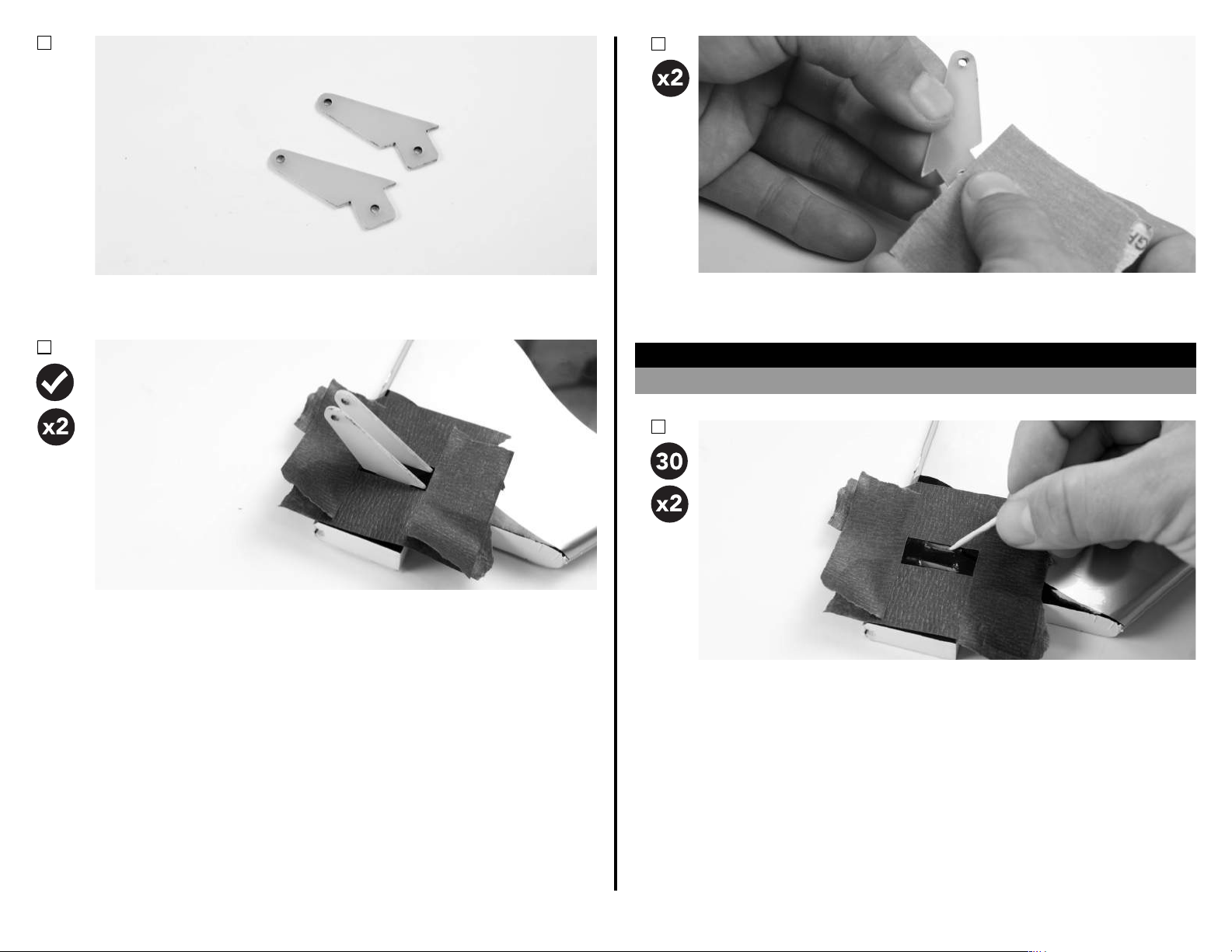
Locate the elevator halves. If using only a single elevator servo, only the le
elevator (if viewed from rear of airplane) is required. Remove covering from
the control horn slots in the boom of the elevator(s).
Locate the rudder. There are two control horn locaons for the rudder
depending on your setup. If using the pull-pull rudder setup, remove the
12
covering from BOTH sides of the upper control horn slots. If using a push-pull
rudder setup, remove covering ONLY from the RIGHT SIDE of the lower control
horn slots.
Page 14
3.
5.
*If using a tail-mounted rudder servo setup, use the second set of elevator
control horns in place of the pull-pull rudder control horns.
4.
Test t the control horns in their corresponding slots. Make any adjustments
necessary to the slots at this me. Once sased with the t of the control
horns, apply low-tack tape approximately 1/32-inch (1mm) away from the
control horns. If using a pull-pull rudder setup, but sure to do this to both sides
of the rudder. Aer applying low-tack tape, remove the control horns from the
slots.
Prepare the control horns by sanding the secon that extends into the control
surface with medium grit sand paper. Use isopropyl alcohol and a paper towel
to remove any excess debris from the control horn.
NOTICE
If not properly scued, glue may not adhere to the control horn, resulng in a failure.
6.
Mix a sucient amount of 30-minute epoxy in a cup, and with a toothpick,
apply epoxy in the control horn slots. Slowly and carefully, insert each control
horn into the surfaces. Parally remove and reinstall the control horn to
ensure that you've completely coated it with glue. Before the epoxy has fully
cured, remove the tape, and clean up any excess epoxy with a paper towel
and isopropyl alcohol.
13
Page 15
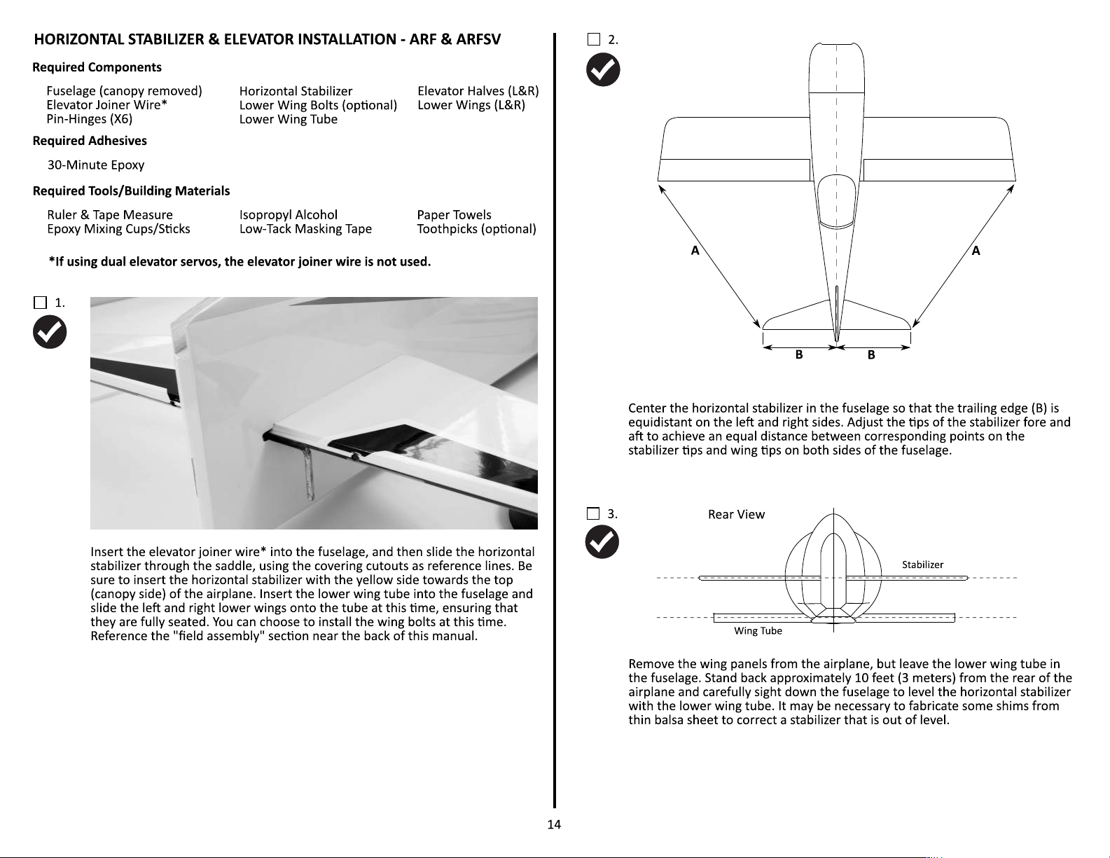
Page 16
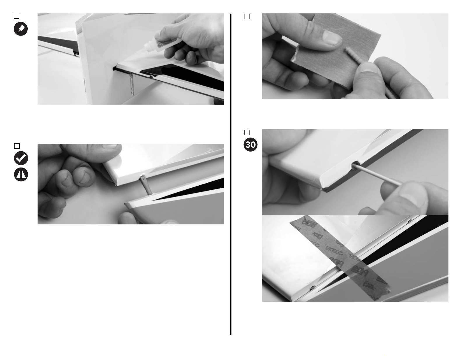
4.
Once sa�sfied with the alignment of the stabilizer, carefully tack it into place
with thin CA, then wick CA around the en�re upper surface of the horizontal
stabilizer. Wait a few moments for the CA to cure, then carefully roll the
airplane inverted to glue the underside of the stabilizer.
5.
6.
Prepare the hinges and elevator joiner wire (if applicable) by sanding them
with medium grit sand paper. Remove any excess debris by cleaning them with
isopropyl alcohol and a paper towel. Apply petroleum jelly to the hinge points
like completed when hinging the ailerons.
7.
Test fit the elevator halves by sliding each elevator half onto the horizontal
stabilizer, indexing the joiner wire* into the slots in the elevator. Ensure that
the elevator halves are properly aligned with each other at the trailing edge
with the elevators centered with the stabilizer. Correct any misalignment by
carefully bending the joiner wire. Do not adjust the slots in the elevator halves.
*joiner wire is not used for a dual elevator servo setup.
15
Mix a sufficient amount of 30-minute epoxy in a cup, and with a toothpick,
smear epoxy in the hinge and joiner pockets of the stabilizer and elevator.
Slowly and carefully, insert each hinge into the stabilizer and elevator. Par�ally
remove and reinstall the hinge or joiner to ensure that you've completely
coated them with glue. Be sure the hinges are oriented so that the elevators
can move properly. Clean up any excess epoxy with isopropyl alcohol, and
tape the elevator in place to cure.
Page 17
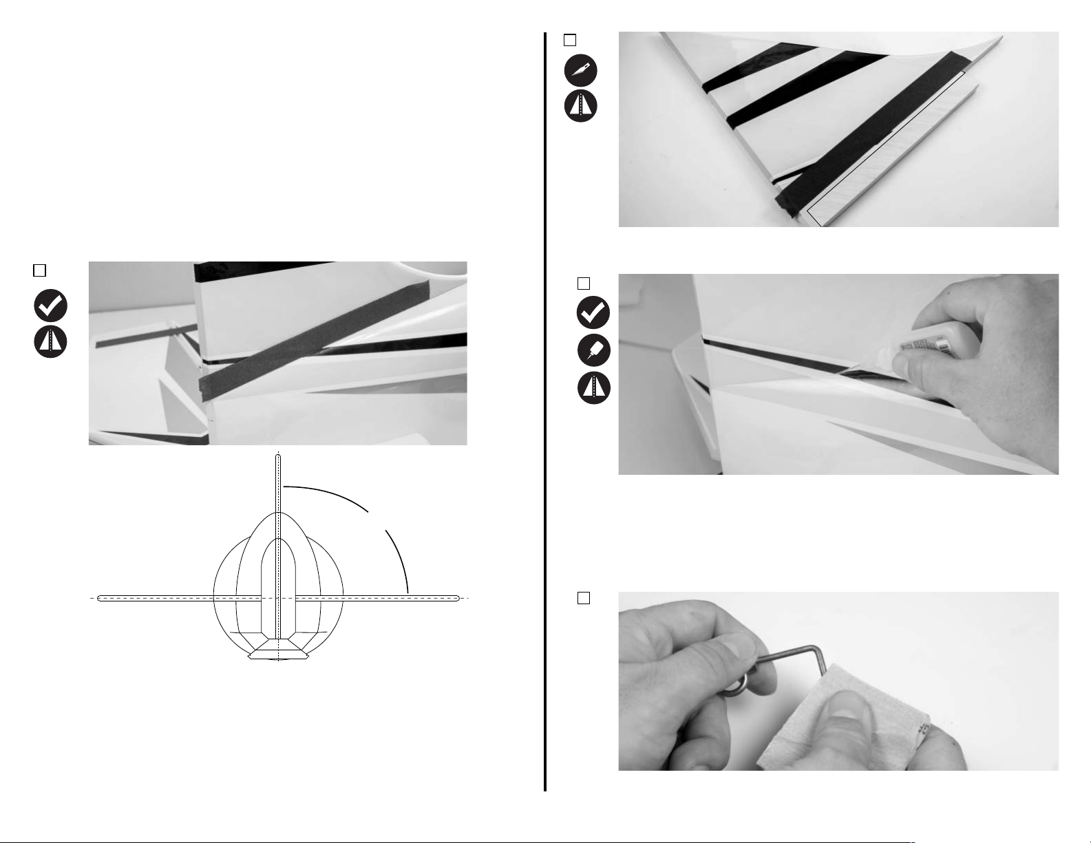
VERTICAL STABILIZER, RUDDER & TAILWHEEL INSTALLATION ARF & ARFSV
Required Components
Fuselage Assembly
Flat Hinges (X4)
Tailwheel
M3 Washer (X2)
Required Adhesives
30-Minute Epoxy
Required Tools/Building Materials
Epoxy Mixing Cups/S�cks
Low-Tack Masking Tape
Flat File
Drill Bits: 1/16-inch (1.5mm)
1.
Ver�cal Stabilizer
Tailwheel Wire
Tailwheel Bracket
Thin CA
Isopropyl Alcohol (91%)
Ruler
Petroleum Jelly
Electric Drill
Rudder
M3 Lock Collar w/Screw (X2)
M3x10 Wood Screw (2)
Paper Towels
Toothpicks (op�onal)
Light Oil
2.
Use a hobby knife with a #11 blade to cut the covering approximately 1/8-inch
(3mm) from the edge of the tape. Stop short of the hinge line. Reference the
above photo.
3.
Rear View
Ver�cal Stabilizer
90˚
Horizontal Stabilizer
Test fit the ver�cal stabilizer into the slot in the fuselage. Check that the
ver�cal fin fits perpindicular to the horizontal stabilizer. If any adjustment is
required, remove a small amount of material from the fuselage. Once sa�sfied
with the fit of the ver�cal stabilizer, apply a strip of low-tack tape on each side
of the ver�cal fin to mark the fuselage loca�on.
16
Re-insert the ver�cal fin into the fuselage slot. Double check alignment with
the horizontal stabilizer. Once sa�sfied with the alignment, use thin CA to tack
the ver�cal fin in place. With the fuselage rolled to a 45-degree angle, apply
thin CA to the corner of the fuse and ver�cal fin to secure it in place. Wait a
few moments, and repeat for the other side of the ver�cal fin. Be sure to get a
good amount of glue on the back sec�on of the fin that extends down the back
side of the fuselage. 30-minute epoxy may also be subs�tuted for thin CA in
this step.
4.
Prepare the tailwheel wire by scuffing the "L" shape bend side of the wire with
medium grit sand paper. This is done to promote glue adhesion when hinging
the rudder.
Page 18
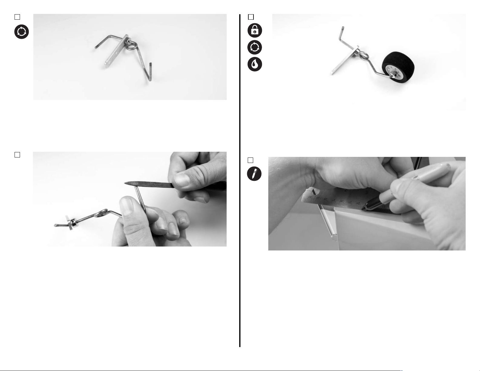
8.
5.
The tail wheel bracket has 3 holes. 2 are slightly smaller than the other.
Assemble the tail wheel wire and bracket by sliding the bracket over the "L"
bent side of the wire, using the larger of the 3 holes in the bracket. This larger
hole is just large enough to t the wire through it. It may be snug, but do not
drill out this hole, as it is important to keep this tolerance ght for proper
longevity of your bracket.
6.
7.
Finish the tail wheel bracket assembly by sliding a M3 lock collar onto the tail
wheel axle with the ange facing the center of the axle. Apply a drop of light
oil on the axle, and slide the wheel onto the axle. Install another M3 lock
collar, with the ange facing the wheel. Apply blue thread lock to the set
screws, ghten them into the lock collars, and on to the at spots created in
the previous steps. Be sure the tail wheel rotates freely.
Use a le to make two small at spots on the inside and outside of the tail
wheel wire for the lock collar set screws.
With the hatches removed from the airplane, and the fuselage inverted on your
work space, use a felt-pped pen to mark a short center line for the tail wheel
bracket down the a end of the fuselage.
17
Page 19
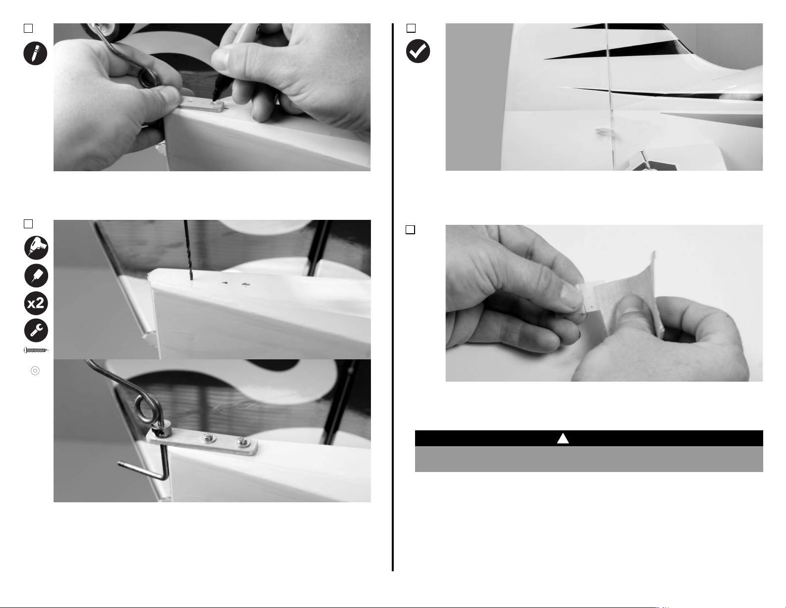
M3x10 (2)
M3 (2)
9.
11.
10.
Using the marks from the previous step, align the tail wheel bracket along this
center line. Mark the two hole locaons with a felt-pped pen, and remove the
bracket.
Test t the rudder hinges and tail wheel wire in the rudder and vercal n.
Make sure all of the hinge slots line up, and that the rudder can move freely.
Adjust as needed. Once sased with the t, remove the rudder and the
hinges from the aircra.
12.
Use medium grit sandpaper to prepare the hinges for installaon. Remove any
excess debris with a paper towel and isopropyl alcohol. Apply petroleum jelly
to the hinge points at this me. This can be applied in the same manner that
was used for the elevator and aileron hinges.
!
WARNING
Petroleum jelly prevents glue adhesion. Do not apply petroleum jelly to the surface
areas of the hinge that require glue adhesion to the wing or surface.
Use a drill and a 1/16-inch drill bit to drill holes at the two marked locaons for
the tail wheel bracket screws. Thread an M3x10 wood screw into the holes to
cut threads in the wood. Remove the screw, and apply a small amount of thin
CA to the holes to harden the threads. Once the CA has cured, install the tail
wheel bracket with two M3x10 wood screws and two M3 washers. Isopropyl
alcohol and a paper towel will remove the pen marks from the covering.
18
Page 20
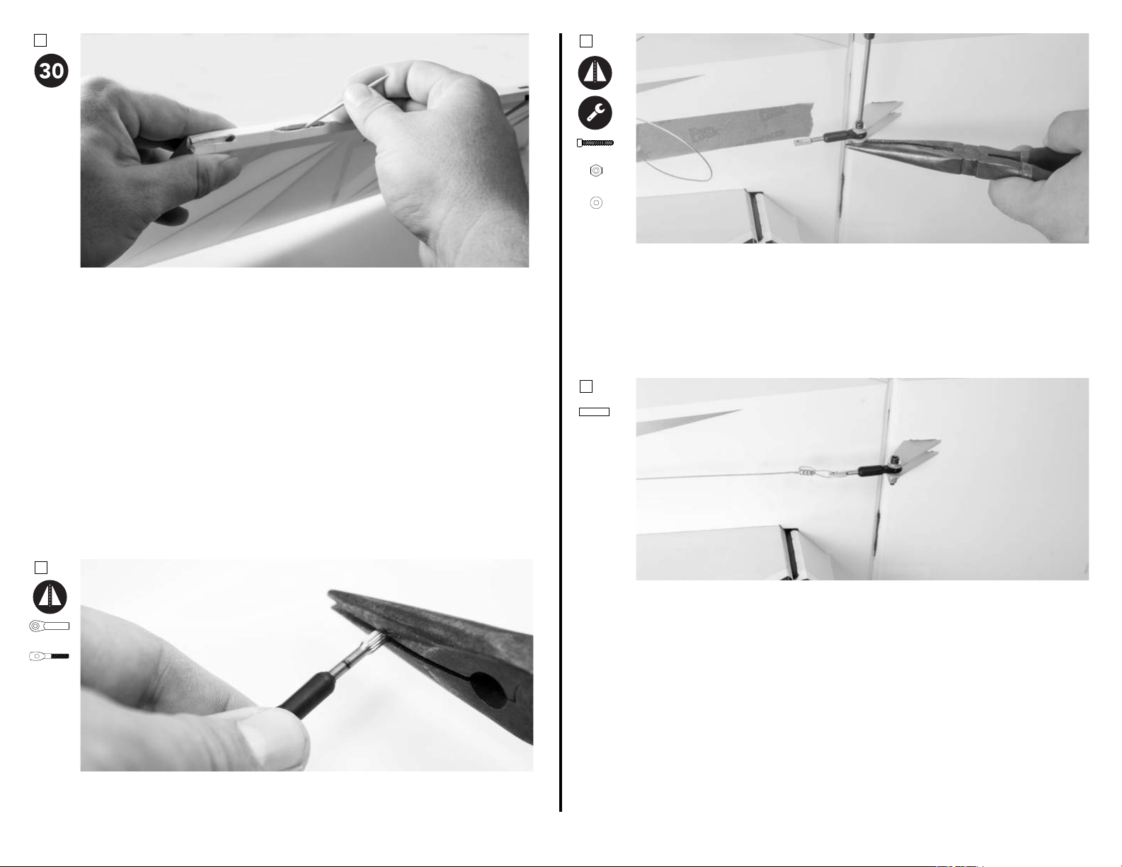
12.
4-40x5/8 (1)
#4 (1)
#4 (2)
Mix a sucient amount of 30-minute epoxy in a cup, and with a toothpick,
apply epoxy in the rudder hinge and tail wheel slots. Slowly and carefully,
insert each hinge into the slots. Parally remove and re-install the hinges and
tail wheel wire to ensure that you've completely coated it with glue. Before
the epoxy has fully cured, tape the rudder to the vercal stabilizer, and clean
up any excess epoxy with a paper towel and isopropyl alcohol.
2.
Aach the ball link to the rudder control horn using a 3/32-inch ball driver and
a 1/4-inch nut driver or pliers. Use the same order of components listed on
page 8 for the control horn side.
You can aach the rudder and elevator linkages to their respecve control
horns following the aileron linkage installaon instrucons on page 8. You can
set nal center of the rudder and elevator control surfaces at this me.
RUDDER AND ELEVATOR LINKAGE FINAL ASSEMBLY - ARF & ARFSV
Required Components
Fuselage
#4 Lock Nut*
Required Tools/Building Materials
Ball Driver: 3/32-inch
1.
Ball Link (1)
Rigging
Coupler (1)
*Number of components required may vary depending on your parcular tail servo setup.
If using a pull-pull rudder servo setup, thread a rigging coupler into a ball link
following the same steps completed earlier on page 10.
#4 Washer*
Ball Link*
Nut Driver: 1/4-inch
4-40 x 5/8 Screw*
Rigging Coupler*
Crimping Tool*
Wire
Crimp (2)
3.
Thread the pull-pull cable through a wire crimp, then through the rigging
coupler and back through the crimp. For extra security, you can loop the wire
back through the crimp a third me. Repeat for the other side of the rudder.
Center the rudder and ghten both cables as needed to keep the rudder
centered. Use a crimping tool to permanently aach the crimp to the cables.
Adjust nal cable tension by removing the ball links and ghtening the ball
links on the rigging coupler as needed. Be sure to keep the rudder centered in
the process. Do not over ghten the cables. Note that the cable may stretch
slightly during the rst ights, and may need ghtened subsequently.
19
Page 21
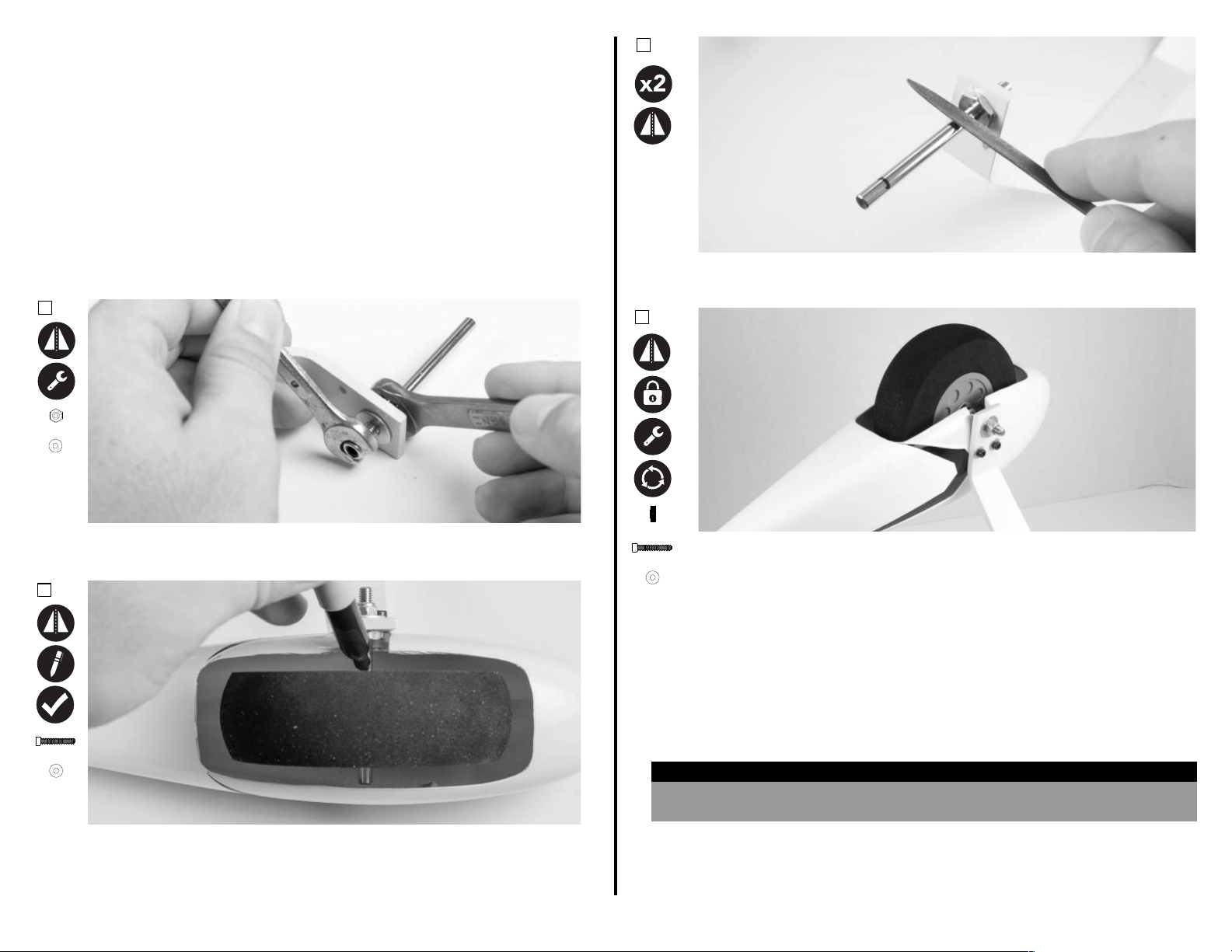
LANDING GEAR INSTALLATION - ARF & ARFSV
Slide an M4 wheel collar onto the axle with the ange aw
Required Components
Fuselage Assembly
Main Wheel (2)
M4 Lock Nut (4)
M3 x 15 Screw (4)
Required Adhesives
Blue Thread Lock
Required Tools/Building Materials
Ball Driver: 3/32-inch
Open-End Wrench: 8mm, 12mm
1.
M5 (1)
M5 (1)
Landing Gear
Axle (2)
M3 Flat Washer (4)
M5 Flat Washer (2)
Nut Driver: 1/4-inch
Felt-Tipped Pen
3.
Wheel Pant (R&L)
M4 x 20 Screw (4)
M5 Lock Nut (2)
M3 Flat Washer (4)
Flat File
Use a at le to make two at spots on the axle where the marks were made
in step 2.
4.
2.
M3x15 (2)
M3 (2)
Assemble the axle to the landing gear leg using a 8mm and 12mm open-end
wrench. Fully ghten at this me.
Temporarily slide a main wheel onto the axle, and aach the wheel pant in
place using two M3x15 screws and two M3 at washers. Center the wheel in
the wheel pant, and mark the sides of the wheel on the axle with a felt-pped
pen. Remove the wheel pant and wheel.
20
M4 (2)
M3x15 (2)
M3 (2)
gear. Use blue thread lock on the set screw, and ghten the wheel collar down
on the mark nearest the landing gear. Slide a main wheel onto the axle,
followed by a second wheel collar with the ange facing the wheel. Use blue
ay from the landing
thread lock on the set screw, and ghten the wheel collar down against the
wheel. Ensure the wheel spins freely.
To install the wheel pants, place an M3 washer onto an M3xXX screw. Apply a
drop of blue thread lock on the screw, and run the screw through the landing
gear leg, threading into the blind nuts located in the wheel pant. Before fully
ghtening, start the second screw (with blue thread lock) for that wheel pant.
Now fully ghten both screws.
HELPFUL HINT
In order to help reduce damage to your model while building, the wheel pants can
be installed last aer compleng the build.
Page 22
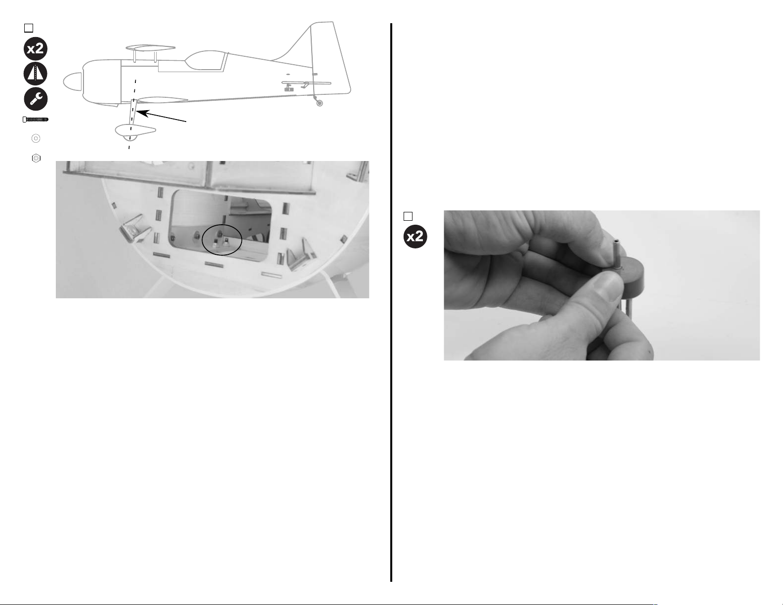
5.
JR
8711
M4x20 (1)
M4 (1)
Note angle of landing gear
FUEL TANK ASSEMBLY - ARF & ARFSV
Required Components
Fuel Tank
Clunk
Required Adhesives
Dish Soap/Water (op�onal)
Required Tools/Building Materials
Pliers
Brass Tubing (x3)
Fuel Stopper
Fuel Line
Stopper Ring
M4 (1)
With the fuselage inverted on your work space, sit the landing gear on the
fuselage so that it sweeps forward as it moves away from the fuselage. Place
an M4x20 screw with an M4 washer through the landing gear, and through the
hole in the landing gear mount in the fuselage. Using needle nose pliers, place
the M4 lock nut on the screw, and �ghten the screw. Repeat for the remaining
3 screws.
You may choose to setup the fuel tank as you wish, but there is enough parts
included in your kit for either a 3-line fuel system or a 2-line fuel system. A 2line fuel system is recommended for it's simplicity and lighter weight. The
instruc�ons below will guide you through installing a 2-line fuel system.
1.
Combine a small amount of dish soap and water in a small pan or bowl. Locate
the holes in the rubber stopper. Apply a very small amount of soap-water
mixture to one of these holes. Using one of the smaller brass tubes, press the
tube through the hole. Repeat for the second brass tube.
21
Page 23
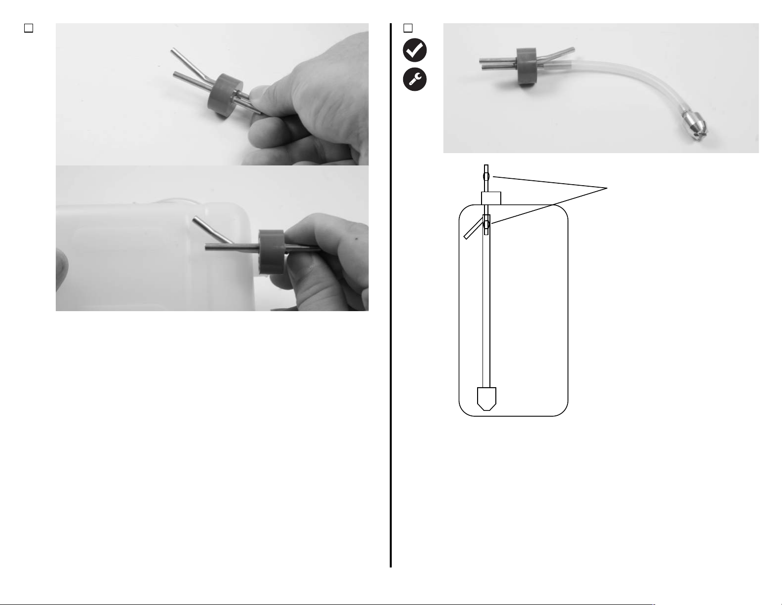
2.
Small Solder Bump
3.
Using a pair of pliers, lightly grasp one of the tubes on the back side of the
stopper (the side with the channel), and make a small bend in the tube as
shown in the photo. This will be the vent side of the fuel system, and this bend
in the tube allows the vent tube to go very near the top of the tank for the
maximum amount of fuel capacity. You can esmate how close to the top of
the tank you have bend the tubing by simply holding the stopper in place near
the side of the tank. You may also extend this piece with a short amount of
gasoline-safe fuel tubing.
Cut a secon of fuel tubing, and aach it to the ll side brass tubing. Aach
the clunk to the opposite side of the fuel line. Assemble these parts so that the
clunk nearly reaches the back side of the tank, but does not make contact with
it. This is very important for this type of model, as gyroscopic maneuvers can
easily get the clunk caught in a poron of the fuel tank. It is crical that the
clunk does not come in contact with the rear of the fuel tank. It is also
important that the fuel line not be too short, or the engine may not pull most
of the fuel out of the tank. This may require a good bit of trial and error before
the proper length is reached. Reference the diagram above. Once happy with
the nal length of your fuel line, secure the line to the brass tube and clunk
using safety wire. You may also add a small "bump" of solder to the brass
tubing to aid in securing the fuel line to the tubing.
22
Page 24
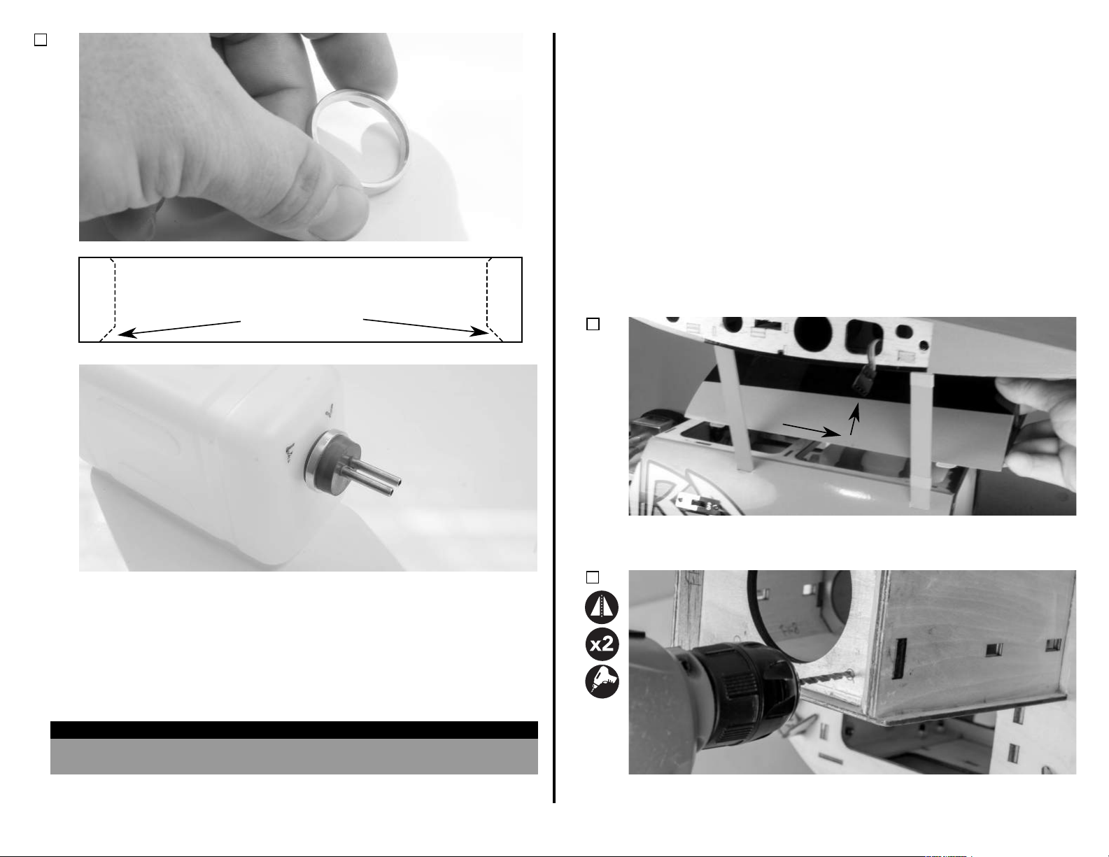
4.
1.
2.
Note large chamfer
ENGINE & THROTTLE SERVO INSTALLATION - ARF & ARFSV
Required Components
Engine
Muer System
Shrink Tubing/String
1/4-20 Blind Nut
Required Adhesives
Blue Threadlock
Required Tools/Building Materials
Electric Drill
The recommended engine and exhaust combinaon for the Mamba is the
DA-70, twin cylinder gasoline engine, with standard muers. However, a
50-60cc single cylinder engine like the DA-60 will also work very well. For
exhaust, the Mamba can use standard muers, or a single canister/pipe of
80mm diameter, with a rear exit. If using a twin engine, and you prefer to use a
tuned pipe or canister, a 2-to-1 header system is required for this aircra.
Consult your engine manufacturer for recommendaons.
1.
Ignion System
Engine Accessories
1/4-20 x 1-1/2-inch Screw (X4)
15mm Engine Standos
(FPM1124 - 15mm Engine Standos (1/4" Inside Hole)
Medium CA (oponal)
Drill Bits: 1/8-inch, 5/16-inch
Throle Servo
Servo Extension - 18"
1/4" Flat Washer
1/4-inch Hex Driver
``
Locate the stopper security ring. Note that there are two chamfers on either
inside edge of this ring. One has a larger chamfer, and the other a smaller
chamfer.
Press the fuel line side of the stopper assembly into the fuel tank. This may
take a good amount of force to seat the stopper properly onto the neck of the
fuel tank. Once fully seated, apply a small amount of soap-water mixture to
the inside of the safety ring. Press the ring over the stopper with the large
chamfer side towards the fuel tank. Set the fuel tank aside for later steps.
HELPFUL HINT
In order to help make future fuel system maintenance easier, you can mark the ll
and vent sides of the fuel tank using a felt-pped pen.
23
Remove the forward hatch by rst removing the rear hatch (if applicable), then
slide the forward hatch rearward, and li up vercally on the enre hatch to
remove it from the fuselage. Install in reverse order.
2.
The motor mounng locaons for the DA-70 and DA-60 are laser-etched into
the rewall for your convenience. Use a 1/8-inch drill bit and drill to create a
pilot hole in the center of these etchings in the rewall.
Page 25
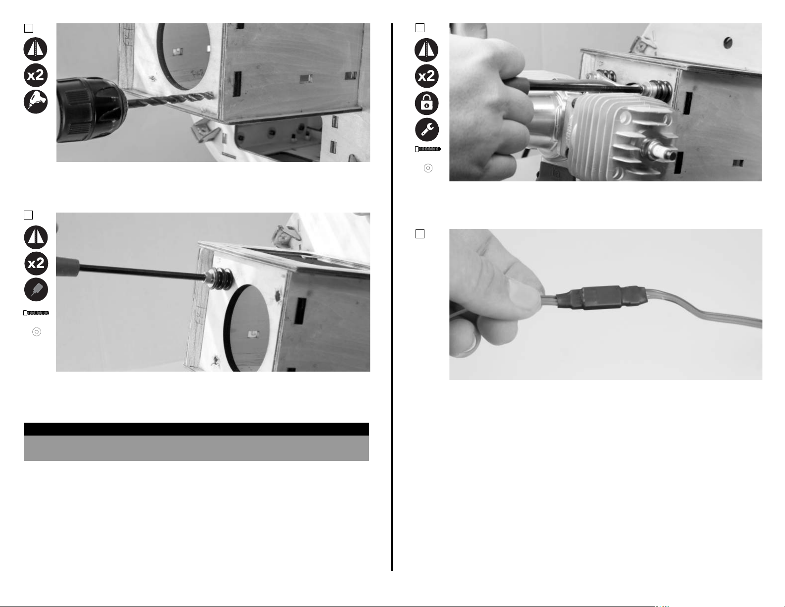
2.
4.
1/4-20x1-1/2 (1)
Use a 5/16-inch drill bit to enlarge the holes from the previous step. Verify
that the hole is large enough to accommodate the blind nuts which will be
installed in the next step.
3.
1/4-20x1-1/2 (1)
#4 (1)
Use a 1/4-20 x 1-1/2-inch screw, 1/4-inch at washer, and 15mm stando to
pull the blind nut into the back side of the rewall. Once fully seated in the
rewall, you may apply some medium CA to help secure the blind nut. Let the
CA fully cure before moving to the next step.
HELPFUL HINT
Depending on your parcular engine or engine manufacturer, it may be easier to
install the fuel line to the engine PRIOR to installing the engine onto the rewall.
#4 (1)
Mount the engine (without exhaust) to the rewall using (4) 15mm engine
standos, (4) 1/4-20 x 1-1/2-inch machine screws, and (4) 1/4-inch at
washers. Be sure to apply blue thread lock to the motor mount screws.
5.
Prepare the throle servo for installaon by installing the rubber grommets
and brass eyelets. Secure a 24-inch servo extension to the servo using shrink
tube or thread.
24
Page 26
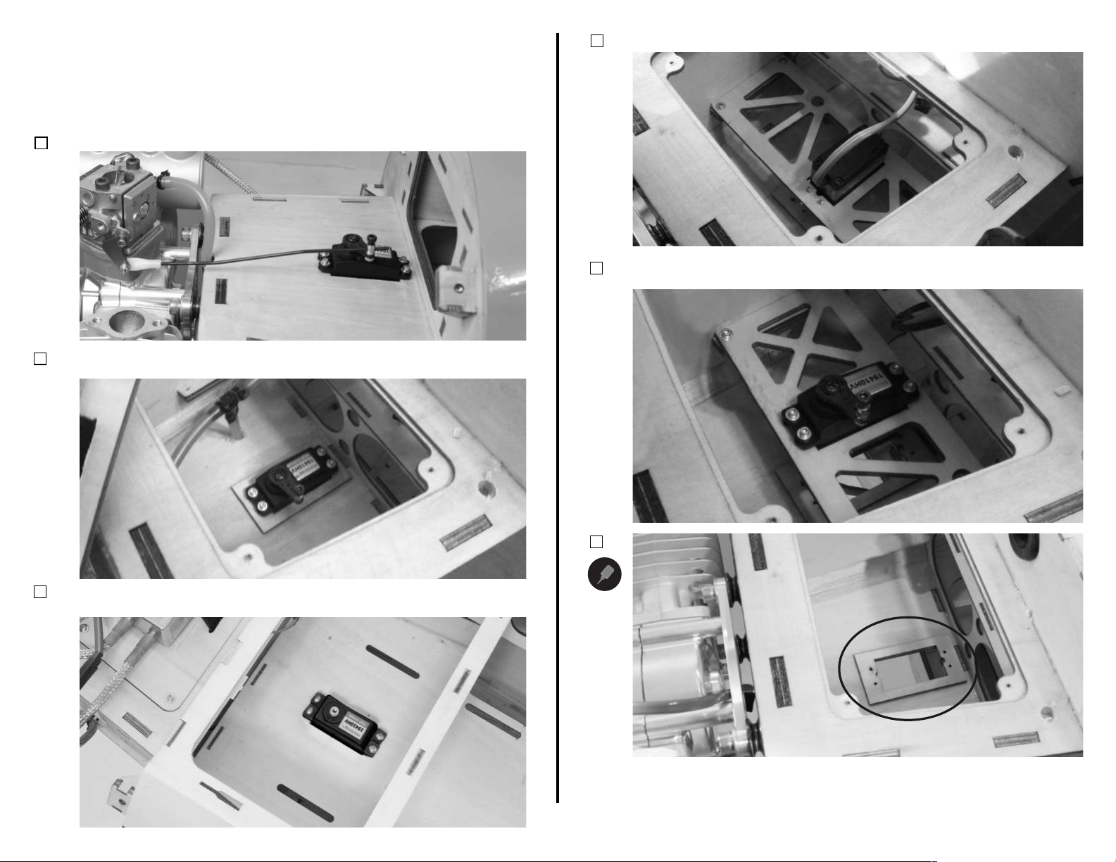
There are several mounng opons for the throle servo in your Mamba.
Throle servo locaon will vary depending on your parcular engine or engine
manufacturer, but always choose the locaon with the best linkage geometry
and least linkage interference to the throle arm on your engine. The
following photos show all of the mounng locaons possible for the throle
servo. The locaon for the DA70 throle servo setup is shown in the rst
photo.
Twin Cylinder with Standard Muers
A.
Single Cylinder, Rear Carburetor, with Standard Muers Choke Servo or
B.
Throle Servo
D.
Twin Cylinder with Canister
Single Cylinder, Rear Carburetor, with Standard Muers or Canister, Choke or
E.
Throle Servo
C.
Single Cylinder, Rear Carburetor, with Standard Muers or Canister, Choke
Servo or Throle Servo.
25
1.
Once you have selected your throle servo locaon, use medium CA to glue
the servo mount doubler in place. Be sure to secure it to the side of the mount
with the BOTTOM of the throle servo. This helps the servo mounng screw
threads to be more secure, and also helps sen the throle servo mounng
locaon.
Page 27
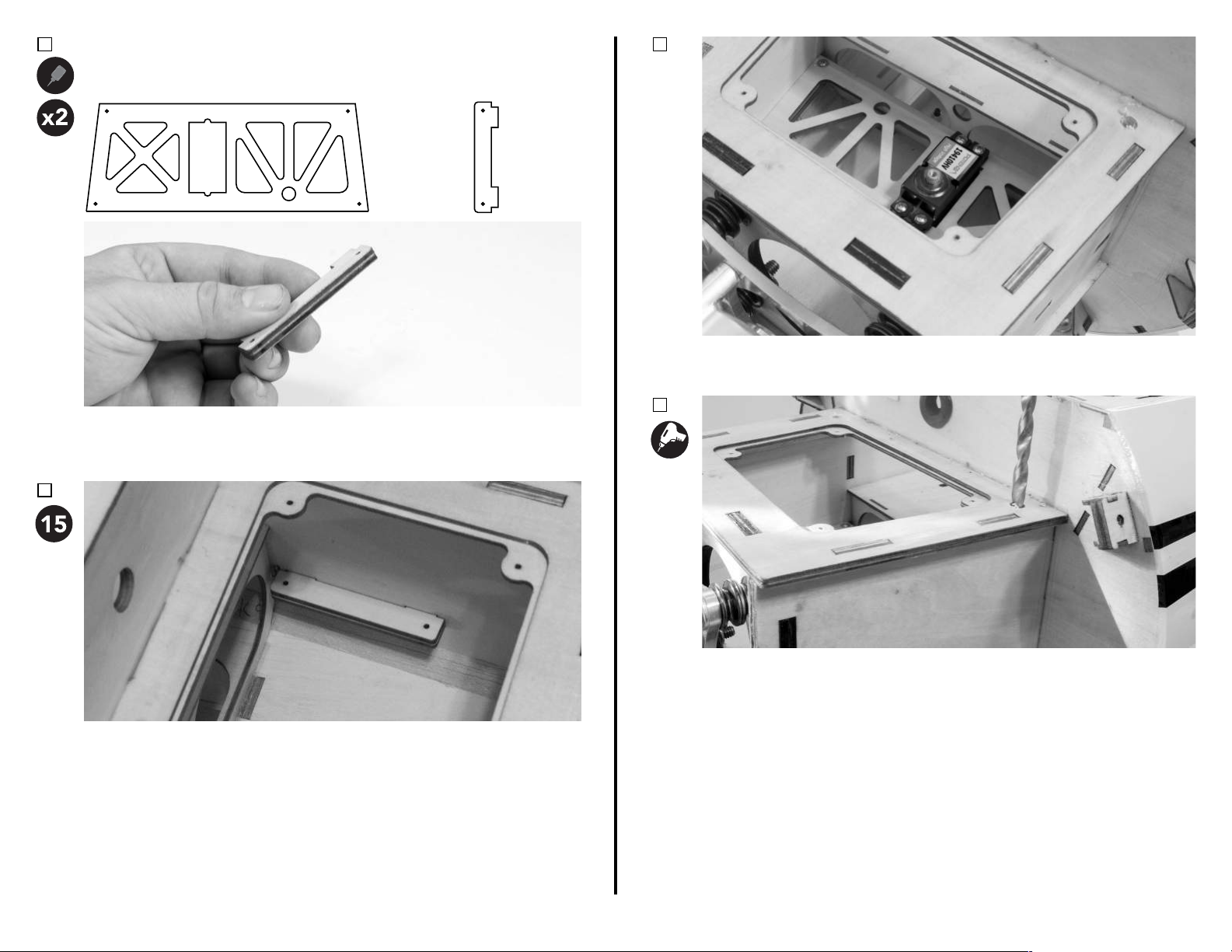
Should your throle servo locaon require the oponal throle servo tray,
2.
complete the following steps to install the tray.
Part A (1)
Locate the wood parts in the drawing above. Using medium CA, glue two "B"
parts together to double their thickness. Repeat this for the remaining two
parts.
3.
Part B (4)
4.
Choose the direcon the tray will be mounted. Reference the photos on page
25.
5.
With the fuselage upright, mix a sucient amount of 15-minute epoxy. Apply
epoxy to the slots in the sides of the motor box, and coat the tabs of the part
"B" assemblies. Slide one assembly into the slots of the motor box, cleaning
any excess epoxy as necessary with a paper towel. Remove and re-insert the
part to ensure you have fully coated the joint with epoxy. Ensure the parts are
fully pressed to the sides of the motor box. Allow the epoxy to fully cure
before moving on to the next step.
Use a drill with a 1/4-inch drill bit to drill two small holes in the top of the
motor box. These holes will allow screwdriver access to the screws needed to
secure the tray in place.
26
Page 28
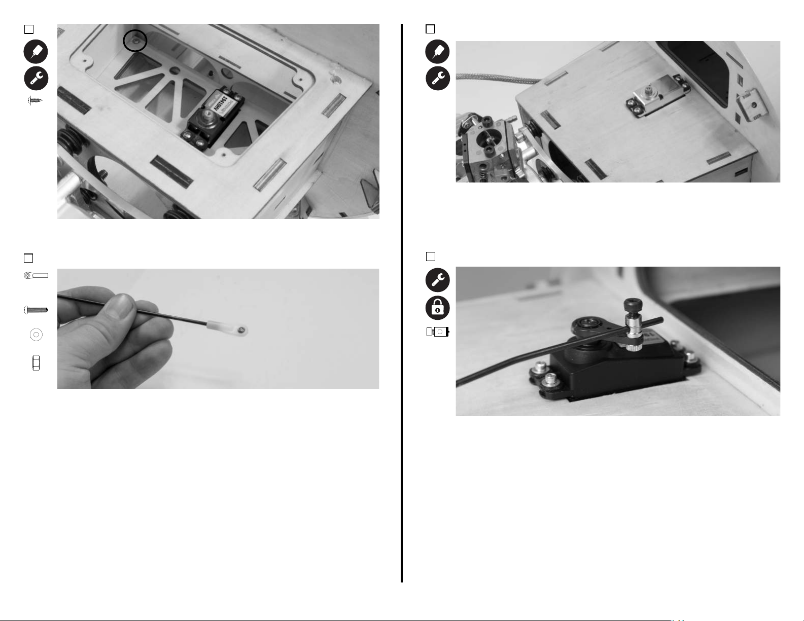
5.
Quick
Connect
(1)
M2.5x8 (1)
Secure the tray in place using (4) M2.5x8 self-tapping screws and a #1 Phillips
screwdriver.
6. (All Throle Servo Locaons)
White
Ball Link
(1)
M2x10 (1)
7. (All Throle Servo Locaons)
Install the throle servo with the output sha towards the nose of the
airplane. Use the radio system to center the servo, then install a 3/4-inch servo
arm with the arm to the side of the fuselage that provides the best linkage
geometry to the throle arm on the engine. In the case of the DA 70, the arm
should go to the right side of the fuselage (from the pilot's perspecve).
8. (All Throle Servo Locaons)
M2 (2)
M2 (1)
Locate the pushrod that is only threaded at one end. Thread this linkage
approximately halfway into a WHITE ball linkage. Secure the ball link to your
engine throle arm using the 2 x 10mm screw, 2mm washers (2), and 2mm
lock nut. Do not use thread lock on these parts, as it can weaken the plasc
insert in the lock nut. The order of these components should be:
Screw
Washer
Throle Arm
Washer
Lock Nut
Secure the quick connector to your servo arm. Be sure to use blue thread lock
for a secure aachment. The order of components is as follows:
Quick connect housing
Washer
Servo Arm
Washer
Nut
27
Page 29
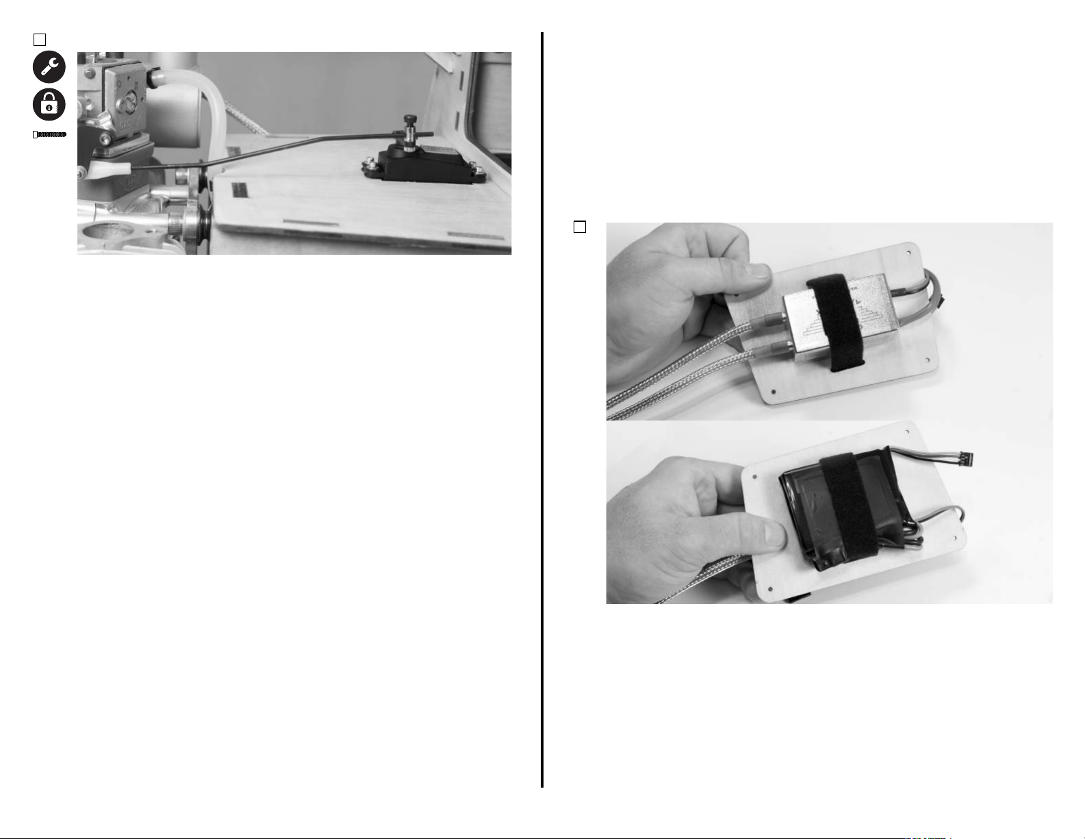
9. (All Servo Locaons)
M3x5 (1)
IG
Remove the M3x5 socket head cap screw from the quick connect. Insert the
non-threaded poron of the throle linkage through the hole in the side of
the quick connect. With the radio powered on, center the throle servo and
engine throle arm. Use blue thread lock, and secure the M3x6 screw onto
the linkage. Check throle posion relave to sck posion, and make any
changes necessary. Fully ghten the screw. Note that it may be necessary to
make a slight bend in the throle linkage to help prevent servo binding.
Reference the photo above for the DA-70. .
NITION SYSTEM INSTALLATION ARF & ARFSV
Required Components
Fuselage Assembly
Regulator (If applicable)
Required Adhesives
Thin CA
Required Tools/Building Materials
Phillips Screwdriver (#1)
1.
Ignion System
Ignion Switch
Hook and Loop Tape
Ignion Baery
Hook and Loop Strap
Install the the ignion per your engine manufacturer's recommendaons. We
recommend installing the ignion and ignion baery on the motorbox using
adhesive-backed hook and loop tape, and a velcro strap. Slots or holes will
need to be cut by a rotary tool into the motor box if you choose to use this
method. Note that the locaon of ignion and ignion baery can aect the
center of gravity of your model. Reference the CG secon at the back of this
manual. The locaon shown in the photos is just one of the many possible
locaons that you can mount your ignion system. Should your parcular
applicaon require a regulator for the ignion, it can be mounted at this me.
28
Page 30
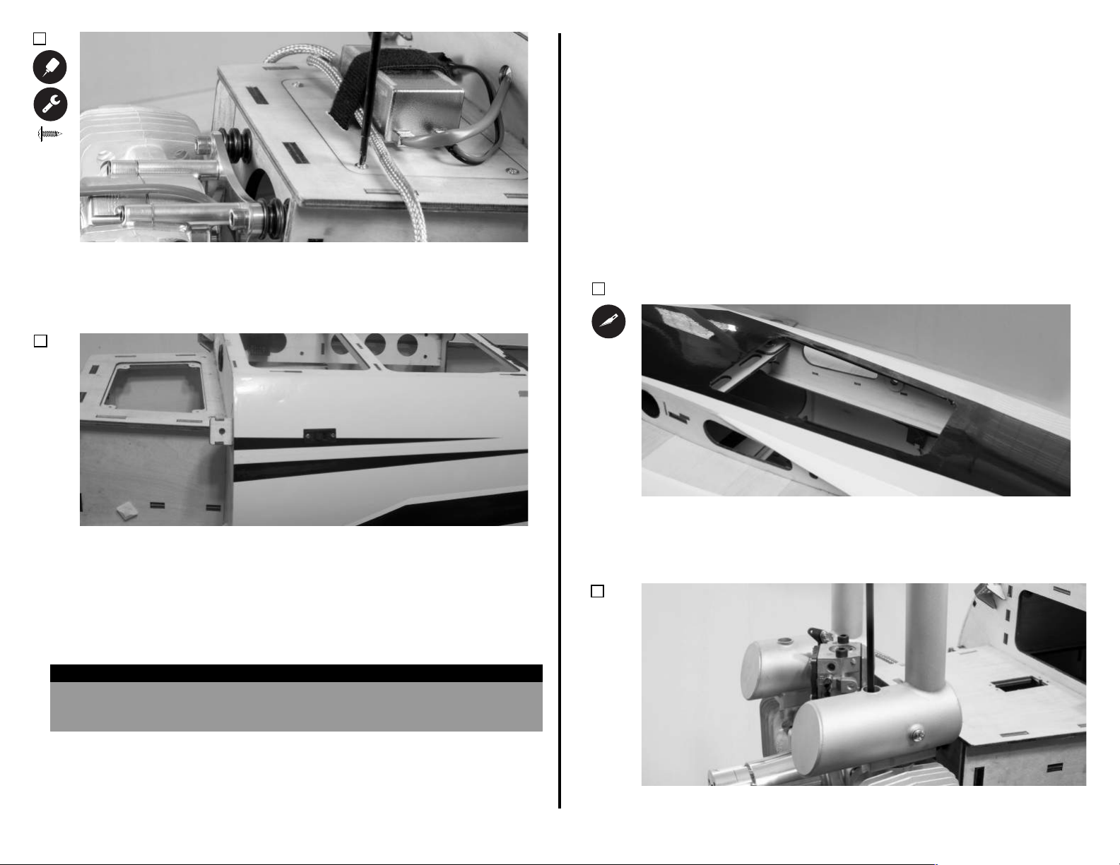
2.
M2.5 x 5
(4)
EXHAUST INSTALLATION ARF & ARFSV
Required Components
Fuselage Assembly
Required Adhesives
Blue Thread Lock
Required Tools/Building Materials
Phillips Screwdriver (#1)
The steps below are broken up into two sec�ons; A and B.
Engine Exhaust
15-Minute Epoxy
Ball Driver: M3, 7/32-inch
Exhaust Accessories
XX
Thread a M2.5 x 5 self-tapping screw into each of the holes located in the top
of the motor box. Remove the screws, and apply a small amount of thin CA to
harden the threads cut by the screw. Once the CA has fully cured, install the
top plate onto the motor box using the M2.5 x 5 self-tapping screws. Be sure
to fully ghten at this me.
3.
Locate the ignion switch hole towards the nose of the fuselage. Note that
there are switch locaons on both sides of the fuselage. Remove the covering
from the hole of your choice using a hobby knife with a #11 blade, and install
your ignion switch. Use blue thread lock if your switch uses screws with
metal to metal contact. DO NOT use thread lock if your screws thread into
plasc! Be sure to make all of the proper connecons to your baery, ignion
module, and regulator (if applicable), and secure those connecons with heat
shrink or thread. Secure any loose wiring to the airframe at this me.
Step A is for standard muffler exhaust systems only
Step B is for a single 80mm canister with a rear exit only
1 A&B.
To aid in cooling, remove the covering from the boom of the fuselage just
a of the lower wing bolt mounng locaon. Leave approximately 1/8-inch
extra covering around the edges, and wrap the covering into the fuselage
using a sealing iron.
2A.
HELPFUL HINT
With the gravitaonal forces applied to today's aerobac models, it is extremely
important to secure any loose wiring to the airframe. Wires that are le loose in the
model can rub against the airframe structure and cause an electronic failure.
29
If using a standard muer system, install your muer system using the
hardware provided by your engine or exhaust manufacturer.
Page 31
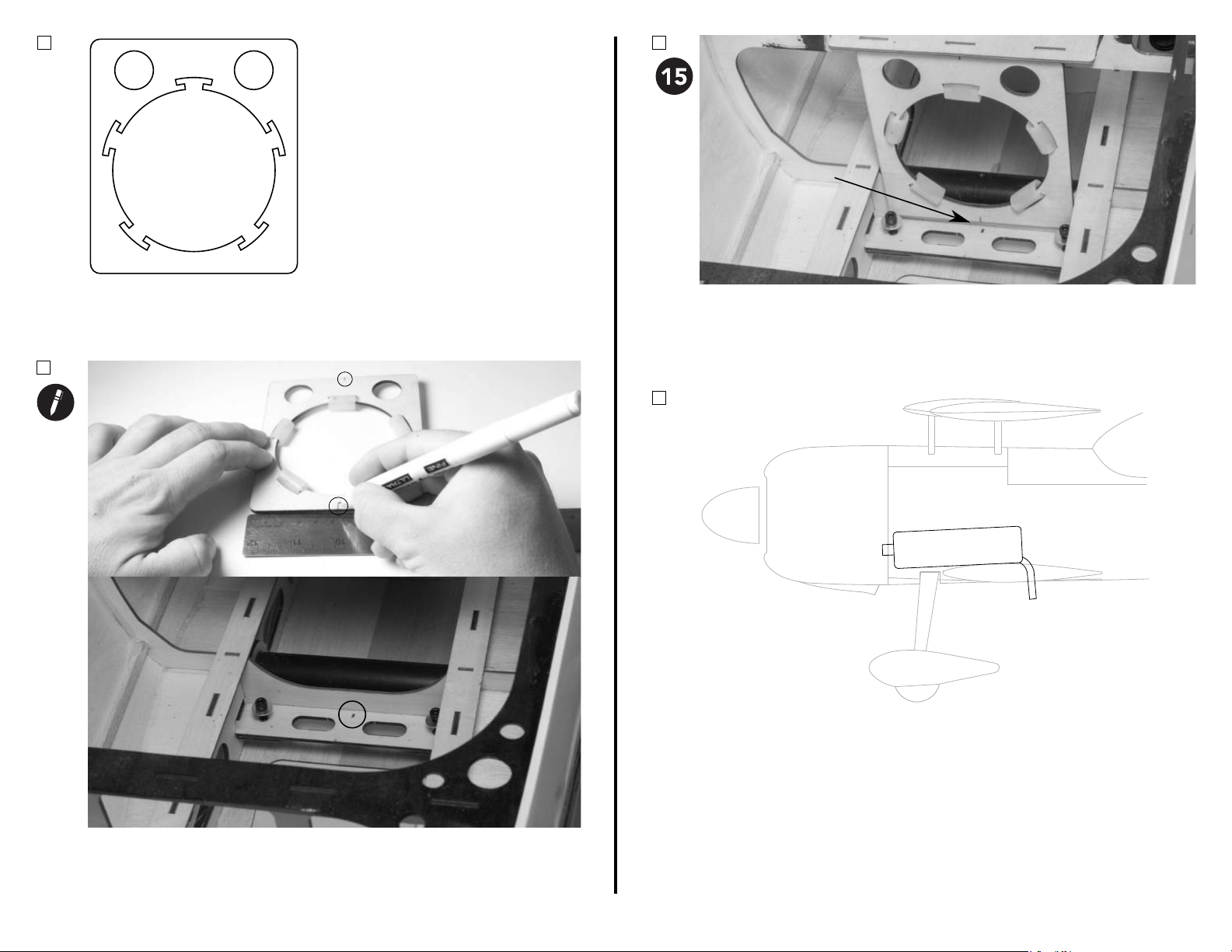
Note Small Gap
2B.
4B.
Locate the canister mount included with your Mamba. This mount is designed
to t a single 80mm canister only. The recommended header drop for the
DA-60 is 0mm. If using the DA70, and you wish to use a canister, a two-to-one
header system with a header drop of approximately 40mm is required.
3B.
Mix a sucient amount of 15-minute epoxy and apply it to the top and
boom of the canister mount. Align the marks made in the previous step, and
ensure the mount is ush against the fuel tank tray above the mount. Note
that the boom of the canister mount will have a small gap to the former
below. Tape the mount in place to cure with low-tack tape.
4B.
Slide the canister into the mount. Depending on the exhaust tube length, you
may need to rotate the pipe 90 degrees to get the exhaust p through the
fuselage mount. Be sure the exhaust exit completely clears the boom of the
fuselage so that no exhaust will escape into the fuselage.
Use a ruler and a pencil to mark center line on top and boom of the canister
mount, as well as the former just a of the fuel tank locaon.
30
Page 32
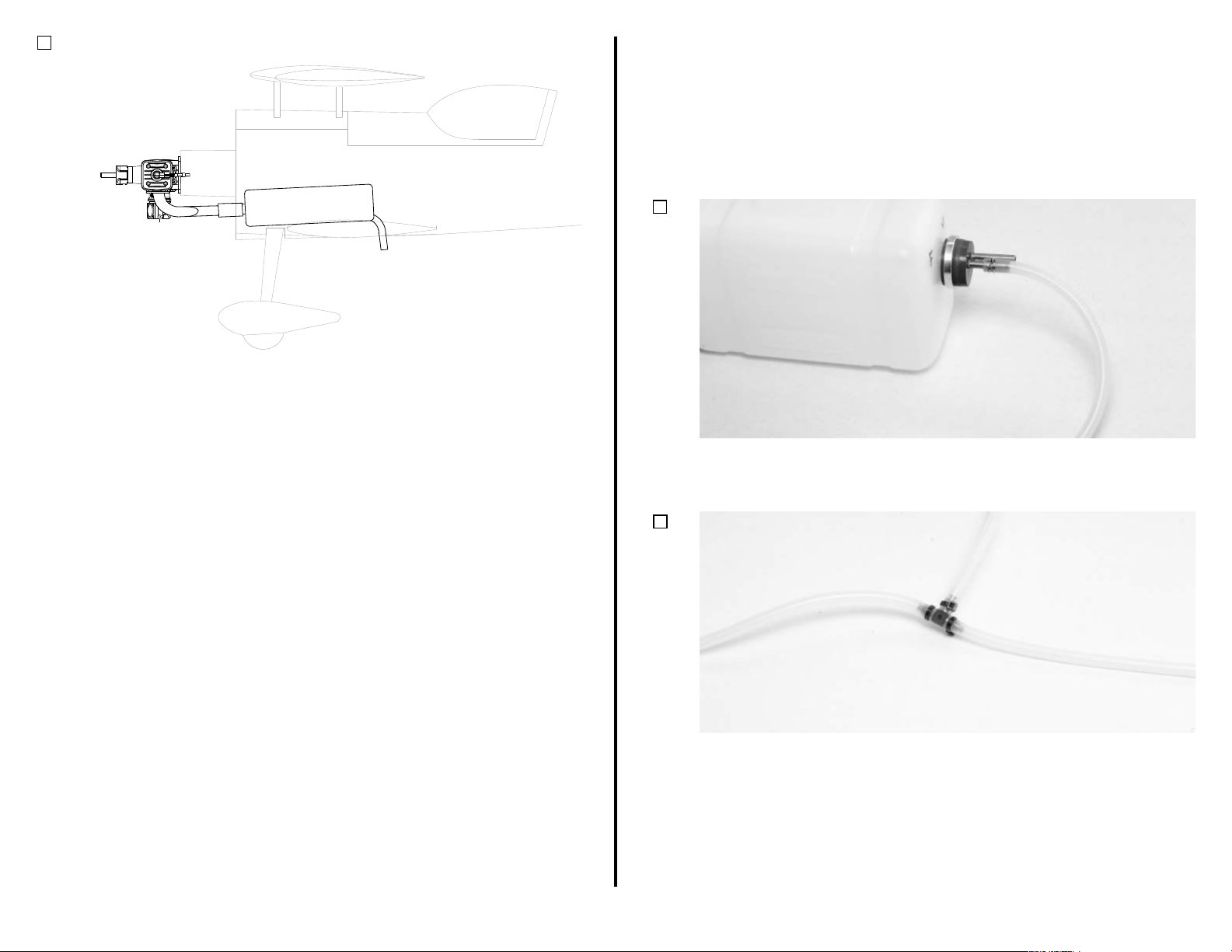
5B.
FUEL TANK INSTALLATION ARF & ARFSV
Required Components
Fuselage Assembly
Fuel Line Clamps
Required Tools/Building Materials
Fuel Tank Assembly
Gasoline-Safe "Large"
Fuel Line
Connect your canister to your header system per your exhaust and header
manufacturer's recommendaons. Once the header is connected to the
canister, aach the header(s) to the engine using the hardware provided by
your exhaust manufacturer.
Hook and Loop Strap (2)
1.
Connect a secon of fuel tubing approximately 12 inches (XXmm) in length to
the ll or "clunk" line of the fuel tank. Secure this secon of line to the brass
tubing using one of the provided fuel line clamps.
2.
Hook and Loop Tape
31
Connect a fuel line "T" to the line you just connected to the fuel tank.
Connect two more 12 inch secons of fuel line to this fuel line "T". Secure all
connecons using a e-wrap or another method of your choosing.
Page 33
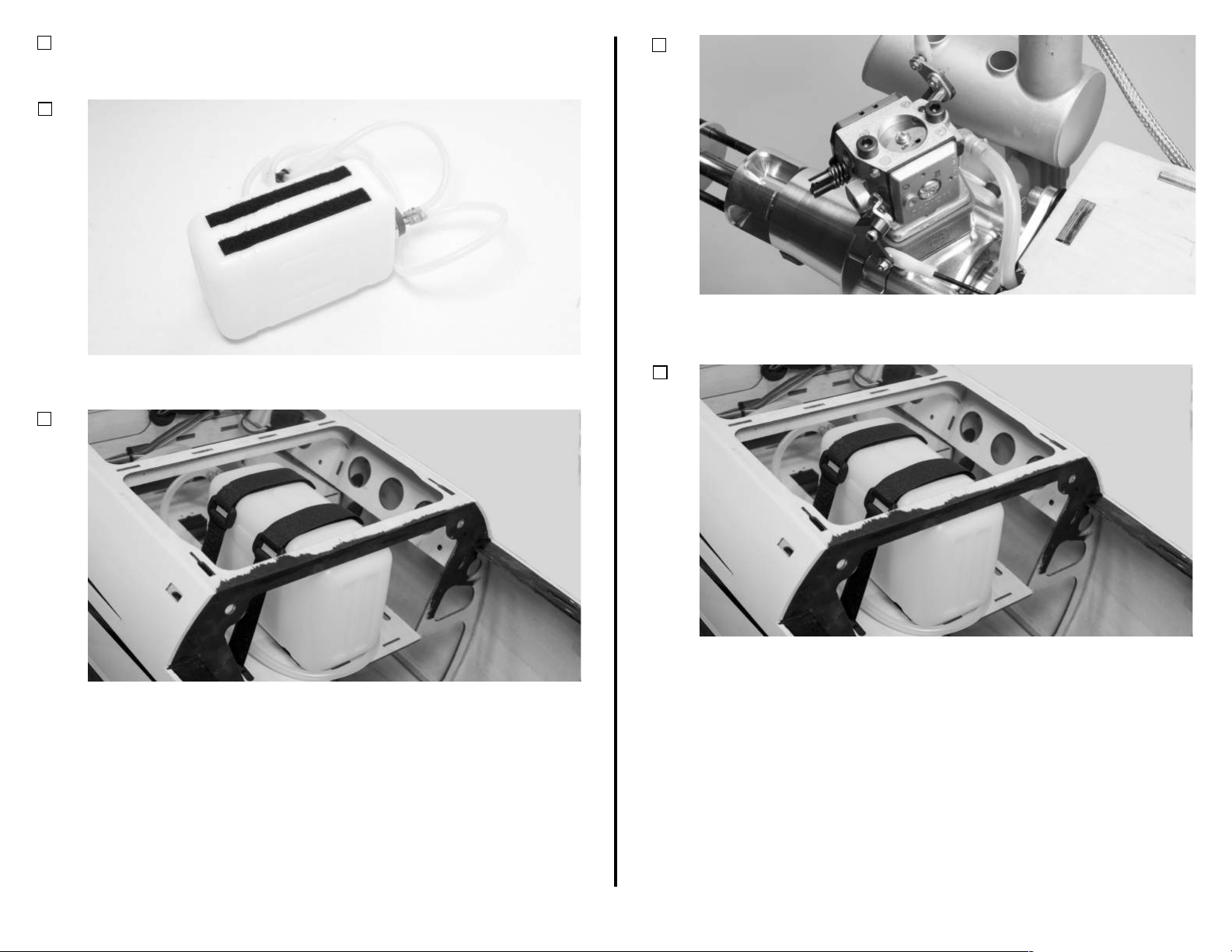
3.
Secure a secon of fuel tubing approximately 36 inches (90cm) in length to
the vent side brass tubing on the fuel tank, following the same instrucons as
the ll side.
4.
6.
Run the clunk line to the engine, and connect it to the carburetor. Secure the
line to the engine using a heat-resistant material like safety wire or a fuel line
clamp.
Apply a vibraon-dampening material (such as foam or hook and loop tape)
to the boom of the fuel tank.
5.
Prepare the fuel tank tray for fuel tank installaon by inserng hook and loop
straps or e wraps though the laser-cut slots in the tray. Place the fuel tank
on the tray, and secure it in place.
7.
Route the vent line such that it goes behind the fuel tank, and exits forward
of the fuel tank near the boom of the fuselage. Secure it in place using a
method of your choosing. Run the ll line from the "T" ng to the same
locaon as your vent line, and use a plug to keep air from entering the fuel
system. The ll line does not need to be wrapped around the fuel tank.
32
Page 34
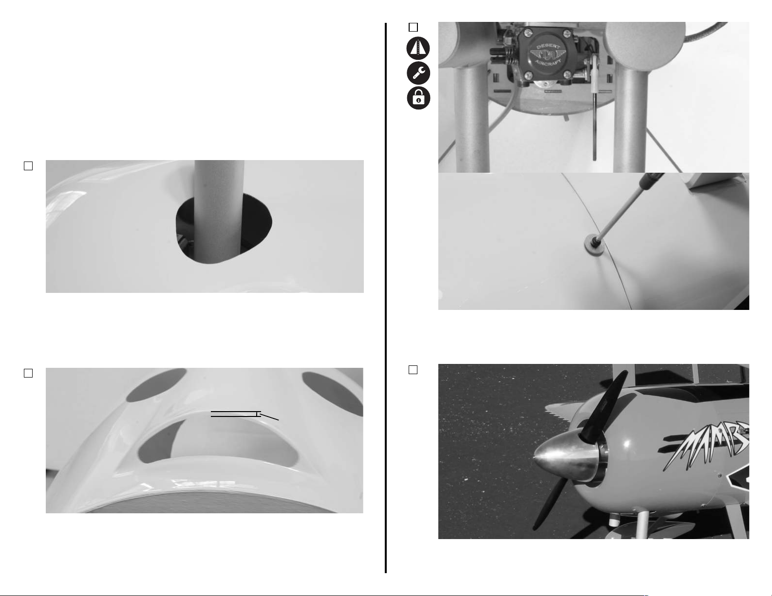
COWLING INSTALLATION ARF & ARFSV
3mm (1/8-inch)
Required Components
Fuselage Assembly
M3 O-Ring (6)
Required Adhesives
Blue Thread Lock
Required Tools/Building Materials
Ball Driver: M3, 7/32-inch
1.
Create and aach any necessary choke linkages prior to these steps. Test t
your cowling. Use a felt-pped pen to mark the locaon that the cowling needs
to be cut for the exhaust to extend through the cowling. Use a rotary tool with a
sanding drum to remove a small amount of material at a me. Ensure that you
have at least 3mm (1/8-inch) of clearance around the exhaust to prevent the
cowling from rubbing the exhaust during ight.
2.
Cowling
M3x15 Screw (6)
M3 Washer (6)
3.
Make and install any necessary choke linkages, and install the cowling using
(3) 3x15mm screws, (3) 3mm o-rings, and (3) 3mm washers. The o-ring should
be placed between the washer and cowling. Be sure to route any choke
linkages out of the cowling before securing it in place.
4.
Before nal installaon of the cowling, use a rotary tool to remove material
from the a side of the cowling scoop to allow airow to exit, and ensure
adequate motor cooling. Be sure to leave approximately 3mm (1/8-inch) of
vercal area to maintain strength in the cowling. Also be sure that you keep all
corners round to help prevent cracking.
Install your propeller and spinner at this me. For the DA-70, we recommend a
Falcon 24x9 gas carbon ber propeller, and a 5-inch aluminum spinner.
33
Page 35
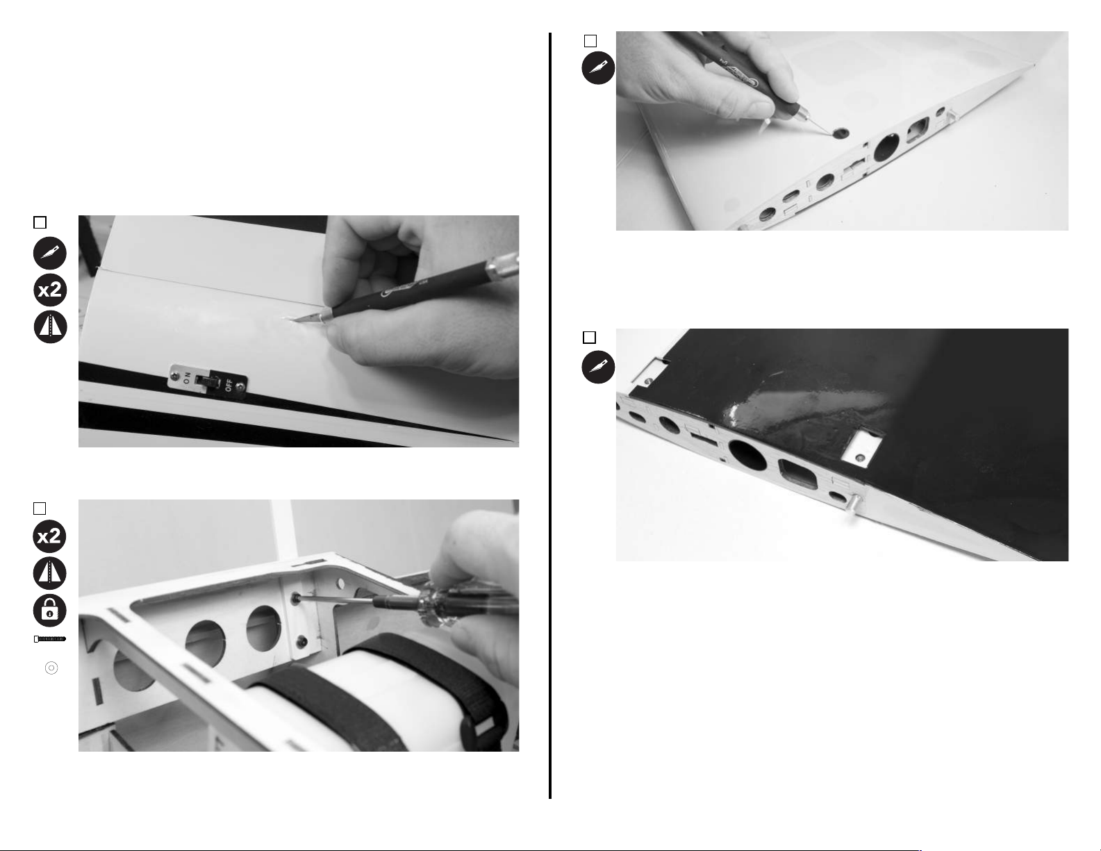
CENTER SECTION INSTALLATION ARF & ARFSV
Required Components
Fuselage Assembly
M3x15 Screw (8)
Required Adhesives
Blue Thread Lock
Required Tools/Building Materials
Ball Driver: M3
1.
Top Wing Center Secon
M3 Washer (8)
3.
Cabanes (4)
Locate the holes for the wing bolts in the top side of the wing center secon.
Remove the covering with a #11 hobby knife blade, being sure to leave
approximately 3mm (1/8-inch) excess inside the hole. Use a covering iron to
seal the covering down into the hole. Be sure to uncover the proper holes, as
there are other similar holes in the top of the wing.
4.
2.
M3x15 (4)
M3 (4)
Locate the holes in the fuselage for the center cabane struts. Remove the
covering from these holes using a sharp #11 hobby knife blade.
Insert a cabane strut into the slot opened in the previous step. Install the strut
using two M3 x 15 screws and two M3 washers. Be sure the top of the strut
extends out towards the wing ps. Repeat this process for the other 3 cabane
struts.
Locate the holes for the cabane struts in the boom side of the wing center
secon. Remove the covering with a #11 hobby knife blade, being sure to leave
approximately 3mm (1/8-inch) excess inside the hole. Use a covering iron to
seal the covering down into the hole.
34
Page 36
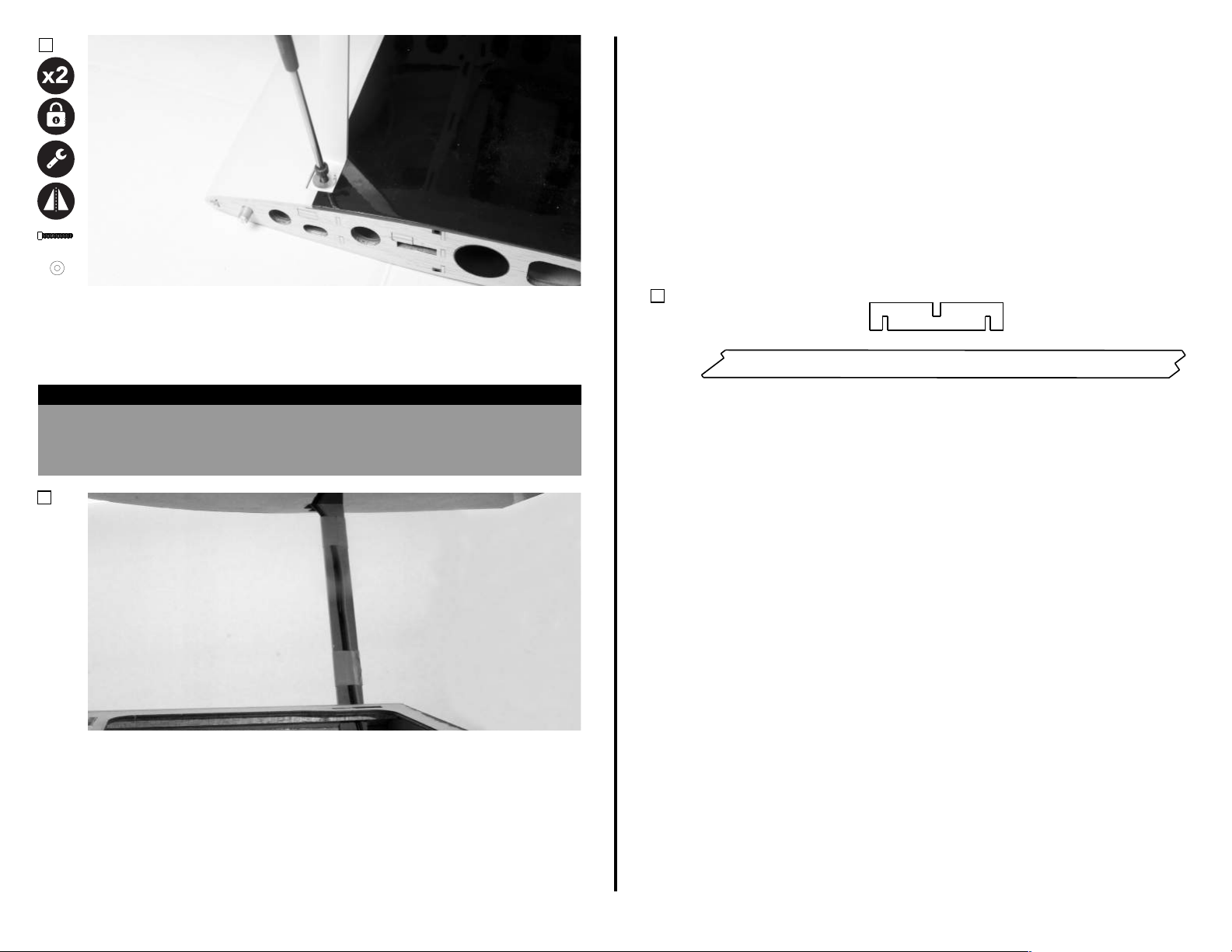
5.
RADIO GEAR INSTALLATION ARF & ARFSV
Required Components
Fuselage Assembly
Receiver Switch
Receiver Baeries
Aura 8 AFCS (Oponal)
Receiver
Aura Brace (Oponal)
Required Tools/Building Materials
M4x8 (4)
M4 (4)
With the airplane inverted on your workspace, and the tops of the struts
accessible, align the center secon with the cabane struts. Use a 3mm ball
driver to insert an M4 x 8 socket head cap screw and M4 washer though the
strut and into the blind nut located in the wing center secon. Fully ghten
the screw.
HELPFUL HINT
To help ensure a true and straight airframe, it is best to start all 4 screws without
ghtening them down fully. Once all four screws have been started, ghten the
screws in an "star" style paern unl they are fully ghtened. This also can help
prevent any alignment issues with other struts or parts.
5.
#11 Hobby Knife
Hook and Loop Straps
Tie-Wraps
Hook and Loop Tape
Required Adhesives
Medium CA
1.
Part A
Part B
If you are using the Aura 8 AFCS, or other stabilizaon system, it should be
mounted forward of the rudder servo locaon in the center of the fuselage,
under the canopy. Locate the Aura brace parts shown in the above drawing. This
brace eliminates tray ex, and is required with the installaon of your Aura 8.
If using the Aura 8, you can download our PRE-CONFIGURED model le at:
www.flexinnova�ons.com/aura
Route two 24-inch heavy duty servo extensions up the rear cabane strut, and
out the wing center secon as shown. Secure the extension to the cabane
struts using e-wraps or tape.
You can also route two 18-inch extensions for the lower wings at this me.
This brace installaon is not required if you are not using a stabilizaon system,
and you can install your radio gear at this me. Various hook and loop strap and
switch locaons oer a variety of mounng locaons for your radio gear.
Note that the center of gravity (CG) may vary considerably depending on many
factors, such as engine selecon, elevator and rudder servo locaons etc. It is
best to mount your receiver baeries in a locaon that provides the proper CG
locaon so that no addional weight is required. Consult the center of gravity
secon of this manual.
35
Page 37
2.
Part A
Locaon
Part A
Top View of Tray
3.
Le Side View of Tray
Part A
2mm
Le Side View of Tray
Part A
Locaon
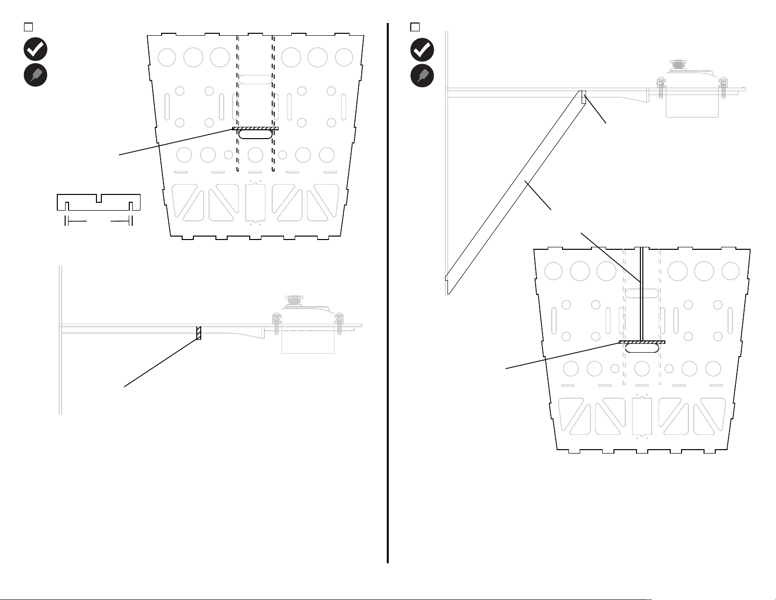
Use medium CA to glue part A to the underside of the radio gear tray. Reference
the drawings above for its locaon. Note that there are two, 2mm thick, pieces
of reinforcement that run under the radio tray. Part A will interlock at the
outsite most notches (2mm) with these two pieces, and should sit perpindicular
and ush against the boom side of the radio tray.
Part B
Locaon
Top View of Tray
Part A
Locaon
Test t Part B in the locaon shown in the drawing above. Once sased with
the t, use medium CA to secure in place.
36
Page 38
SHARK TEETH INSTALLATION ARF & ARFSV (OPTIONAL)
Tip Rib
Required Components
Main Wings (4)
Required Adhesives
15-Minute Epoxy
Required Tools/Building Materials
Shark Teeth Strips (4)
3.
Low-Tack Tape
Isopropyl Alcohol
1.
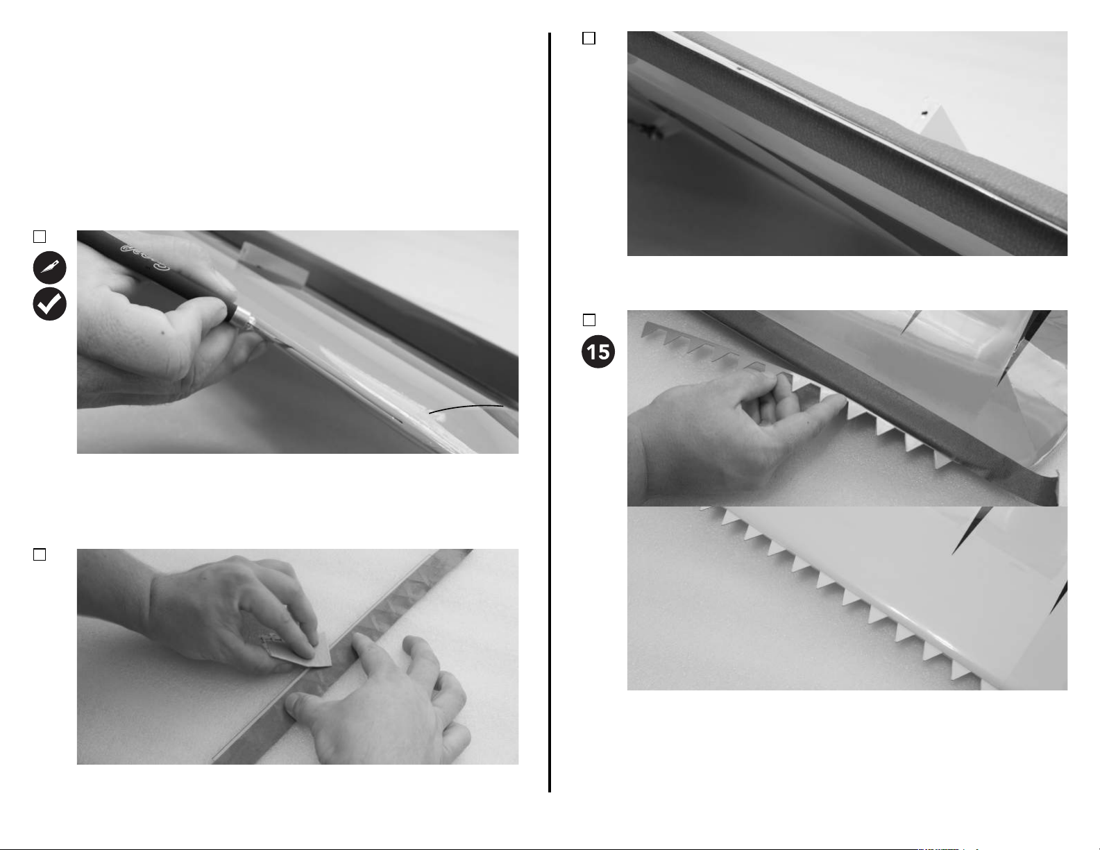
Locate the slots in the leading edge of the wing star�ng at the �p rib just
before the taper at the �p of the wing. Each shark tooth slot is approximately
11-3/4-inches (300mm) in length from the �p rib. Use a #11 hobby knife to
open the slots at the leading edge of each wing panel. Test fit the shark teeth
strips into these slots. Ensure everything fits and aligns properly.
2.
Mixing Cups
Paper Towels
Mixing S�cks
Apply low-tack tape on each side of the slot in the wing panels. Leave a small
gap approximately 1/16-inch (1.5mm) between the tape and the slot.
4.
Apply low-tack tape to the shark tooth strips, leaving only the area that
extends into the wing panel uncovered. Use a medium grit sand paper to sand
both sides of this exposed area.
Mix a sufficient amount of 15-minute epoxy, and use a toothpick to apply it
within the slot in the leading edge of the wing. Insert the shark tooth strip
into the wing, being sure it has been fully coated with epoxy. Before the epoxy
fully cures, remove the tape, and clean up any excess with isopropyl alcohol
and paper towels.
37
Page 39
FIELD ASSEMBLY ARF & ARFSV
Required Components
Fuselage
Strut Retaining Pins
M4x15 SHCS (4)
Required Tools
M3 Ball Driver
Required Adhesives
Tape
1.
M4x15 (2)
M4 (2)
Wings (4)
Fuselage Hatches
M4 Washer (4)
5Interplane Struts
Wing Tubes (2)
M4 O-Ring (4)
2.
M4x15 (2)
M4 (2)
Repeat the same process for the top wing panels.
3.
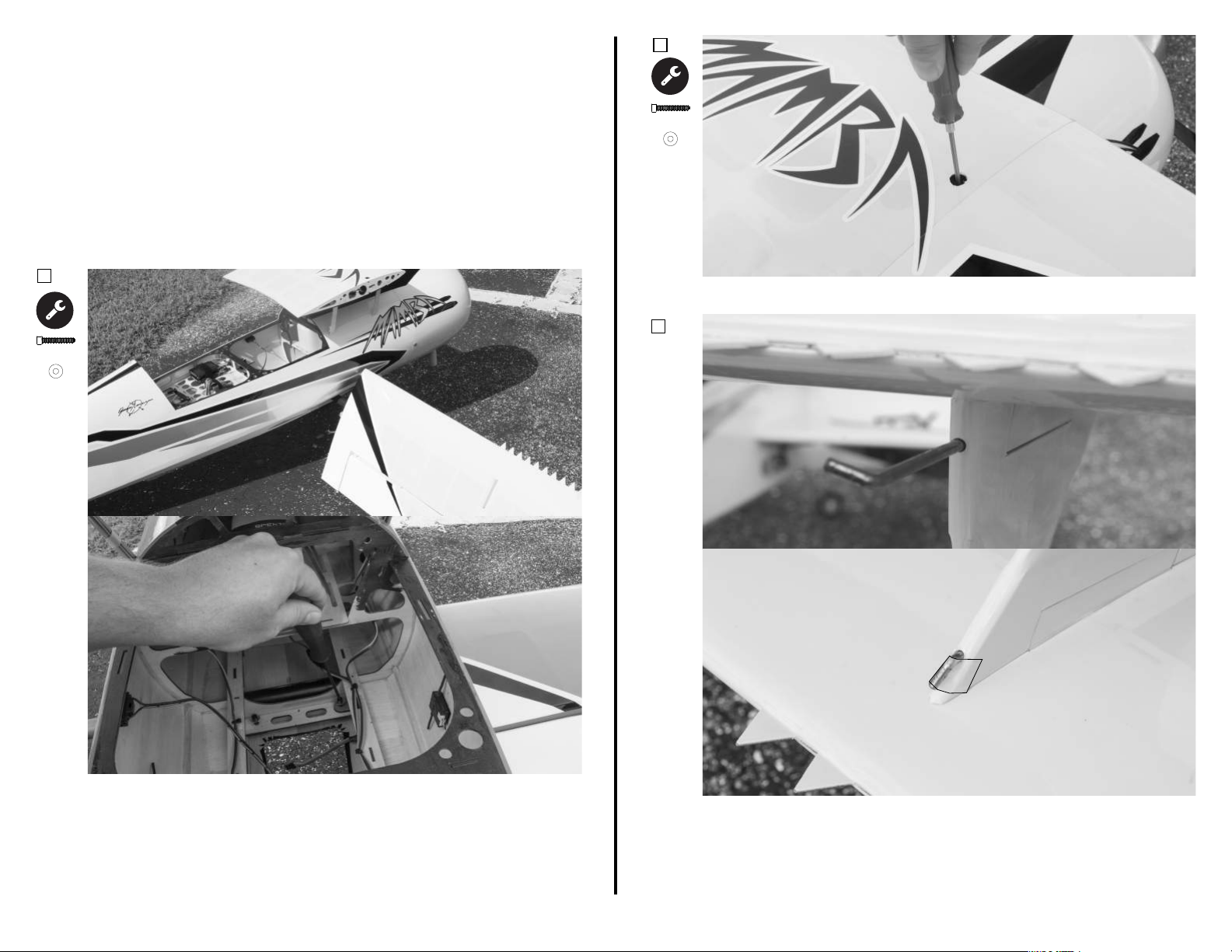
Remove the rear canopy hatch from the fuselage. Slide a wing tube into one
lower wing panel. Parally slide the wing tube (with wing) into the lower wing
tube socket. Be sure there are no bolts in the wing bolt locaon. Secure the
aileron servo lead to the servo extension, and fully slide the wing into place,
being sure not to pinch any wiring between the wing and fuselage. Secure the
wing with an M4 x 10 socket head cap screw M4 washer, and M4 o-ring.
Repeat for the other lower wing.
Be sure the interplane strut wire is removed from the strut. Slide an
interplane strut into place. Note that the struts are direconal, and will only
t one way. Push the straight end of the wire through the strut, and through
the wing strut block unl the angled poron of the wire is ush with the
strut. Secure the wire with tape. Repeat for both top and boom sides of
each strut.
38
Page 40
CENTER OF GRAVITY
Seng the center of gravity is one of the most important steps for success, parcularly with a new airplane. The Premier Aircra Mamba 70cc is a high-performance airplane with large
control surface throws, and a very high thrust to weight rao. These two factors combined make the Mamba a very enjoyable aircra to y, but if the center of gravity is not within an
acceptable range, it will make the airplane dicult, if not impossible, to control. In order to have the most success and enjoyment from your Mamba, please follow the next few steps
very carefully.
Before balancing your model, please ensure that all of the components are installed in your airplane when checking CG. This means the baeries, servos, linkages, hardware, propeller,
spinner; everything. The airplane must be in ready-to-y condion, otherwise the measurement will not be accurate.
There are several methods for determining center of gravity, from using a CG machine, to using ngers and a friend. Regardless of the method used, ensure that the tests are accurate
and repeatable. If there are any inconsistencies between measurements, work to isolate the source of the error(s) to ensure that the test can be repeated with the same results. If
liing the model by the wing ps, do NOT li directly from the p of the wing, but li at the p-most wing rib locaon or damage to the model may result.
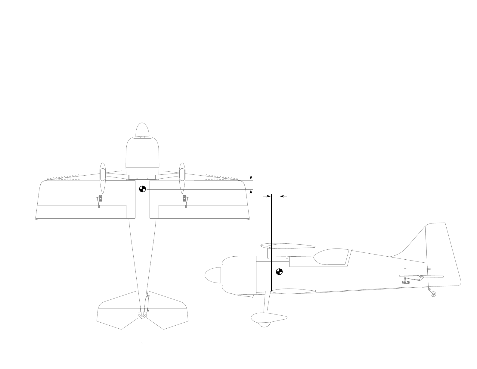
The locaon of the center of gravity for the Mamba 70cc is 81mm (3-3/16-inches) AFT from the LEADING EDGE of the BOTTOM WING. It is crical that the starng point for your
model be at this point. This measurement is determined from many test ights by designer and many me world aerobac champion, Quique Somenzini.
81mm
(3-3/16-inches)
8711
JR
8711
JR
8711
JR
39
Page 41
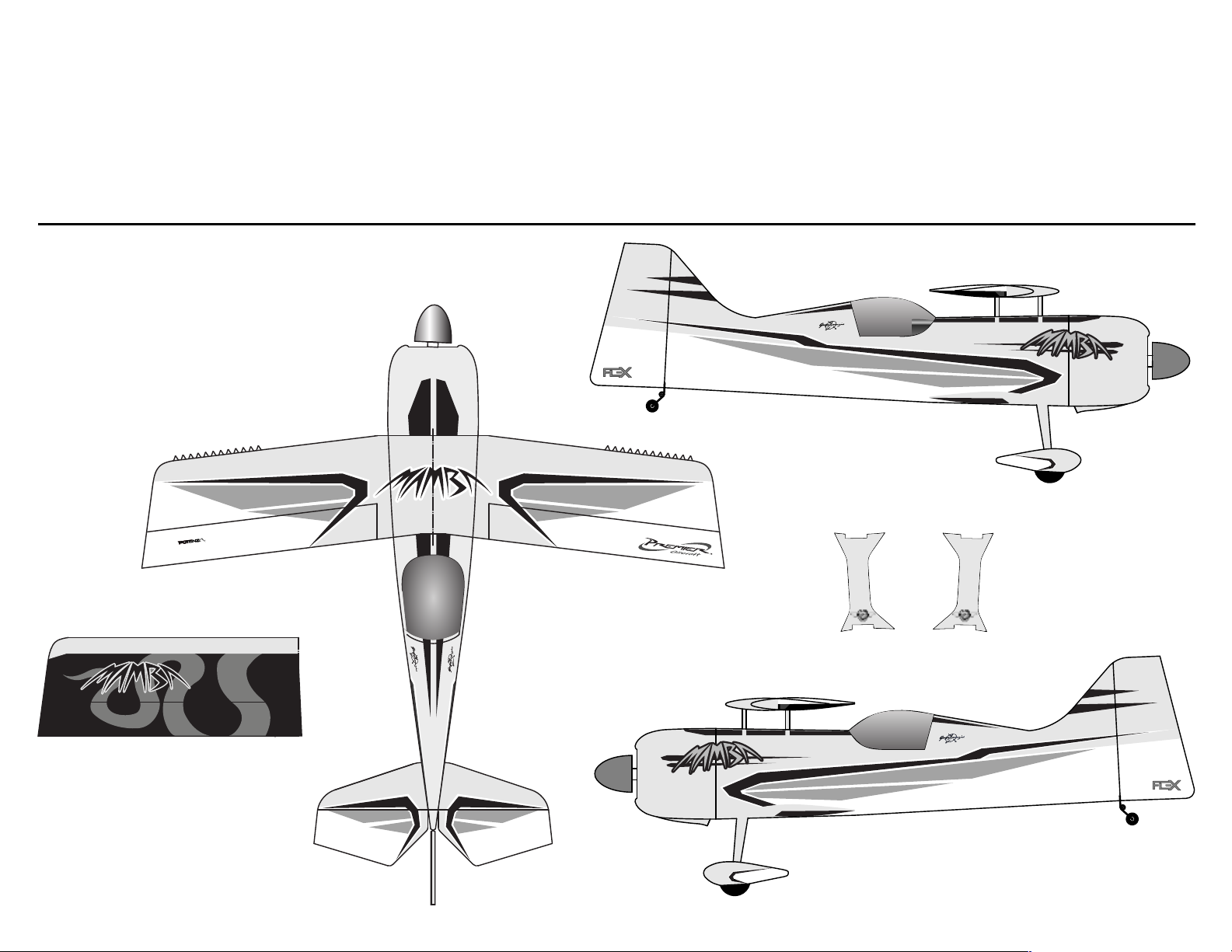
DECAL INSTALLATION
Aura
Use the photos provided below, as well as the images on the box for a guide to apply
decals to your model.
Thoroughly clean the model to ensure that it is free of oil, ngerprints, and dust.
1.
Separate the decals, but do not remove the paper backing at this me.
2.
Prepare a dishpan or small bucket with a mixture of warm water and liquid dish
3.
detergent. The rao should be approximately one teaspoon per gallon of water.
Submerse the decal into the water/soap mixture and gently remove the paper backing.
4.
Removing the backing under water prevents ngerprints from being visible on the
back side of the decal.
Apply some water/soap mixture with your palm to the area desired. Once the are is
5.
saturated, posion the scker on the airplane. Even though these are not water
transfer decals, using wet applica�on methods allows the s�cker to be reposi�oned,
reduces bubbles, and eliminates fingerprints and other blemishes from being visible.
Hold the decal in place and use a paper towel to gently wipe most of the water away.
6.
Use a so piece of balsa or similar and squeegee the remaining liquid from
7.
underneath the decal.
Repeat unl all decals are applied. Do not move, or otherwise touch the model for at
8.
least 12 hours to allow the rest of the water to evaporate.
TM
INNOVATIONS
Le Strut
Right Strut
8
TM
INNOVATIONS
40
Page 42
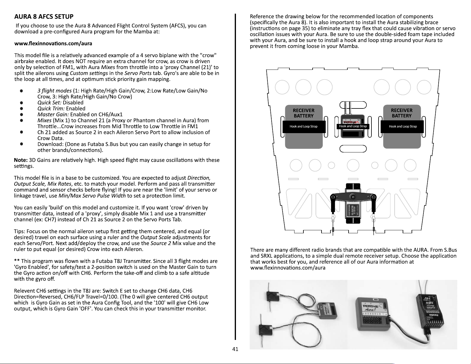
Page 43
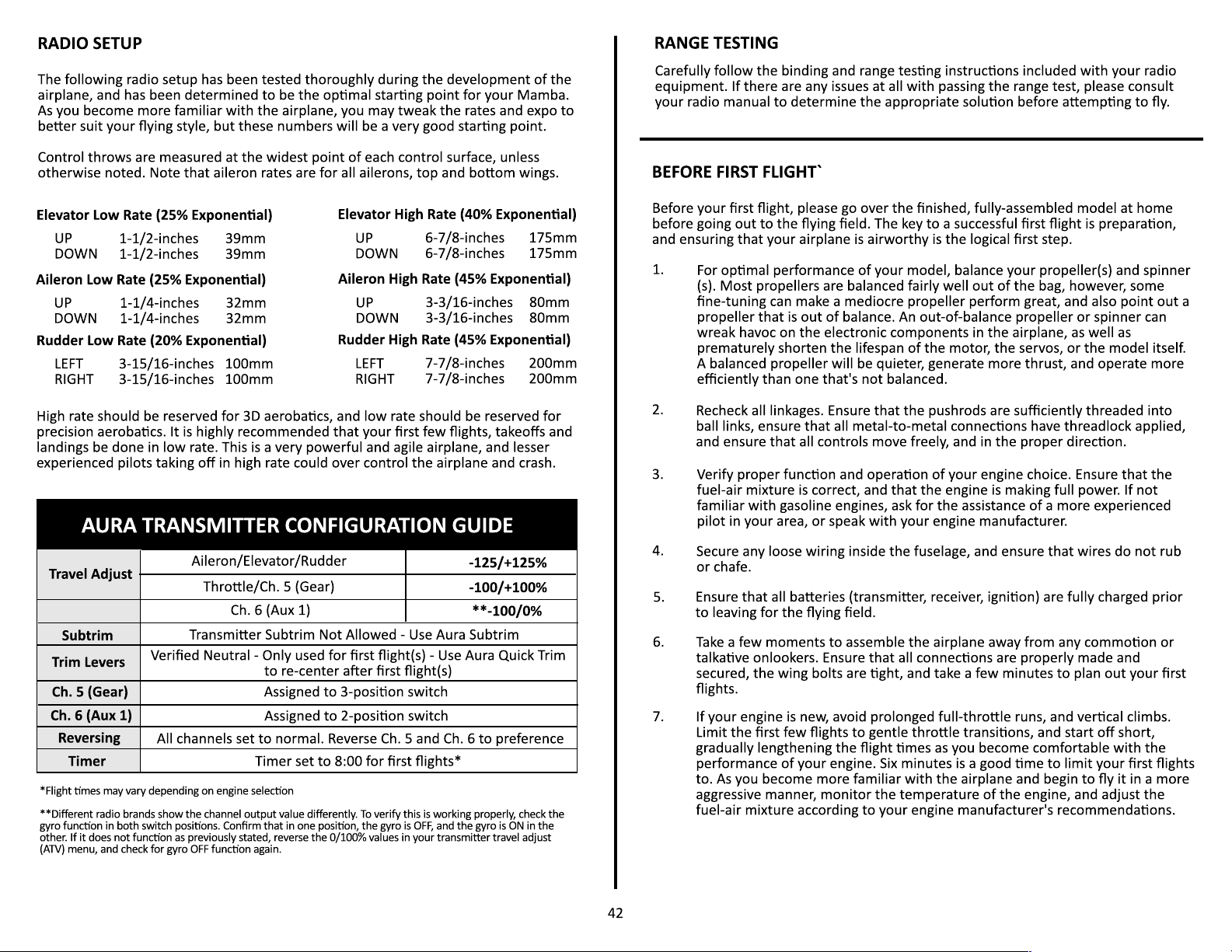
Page 44
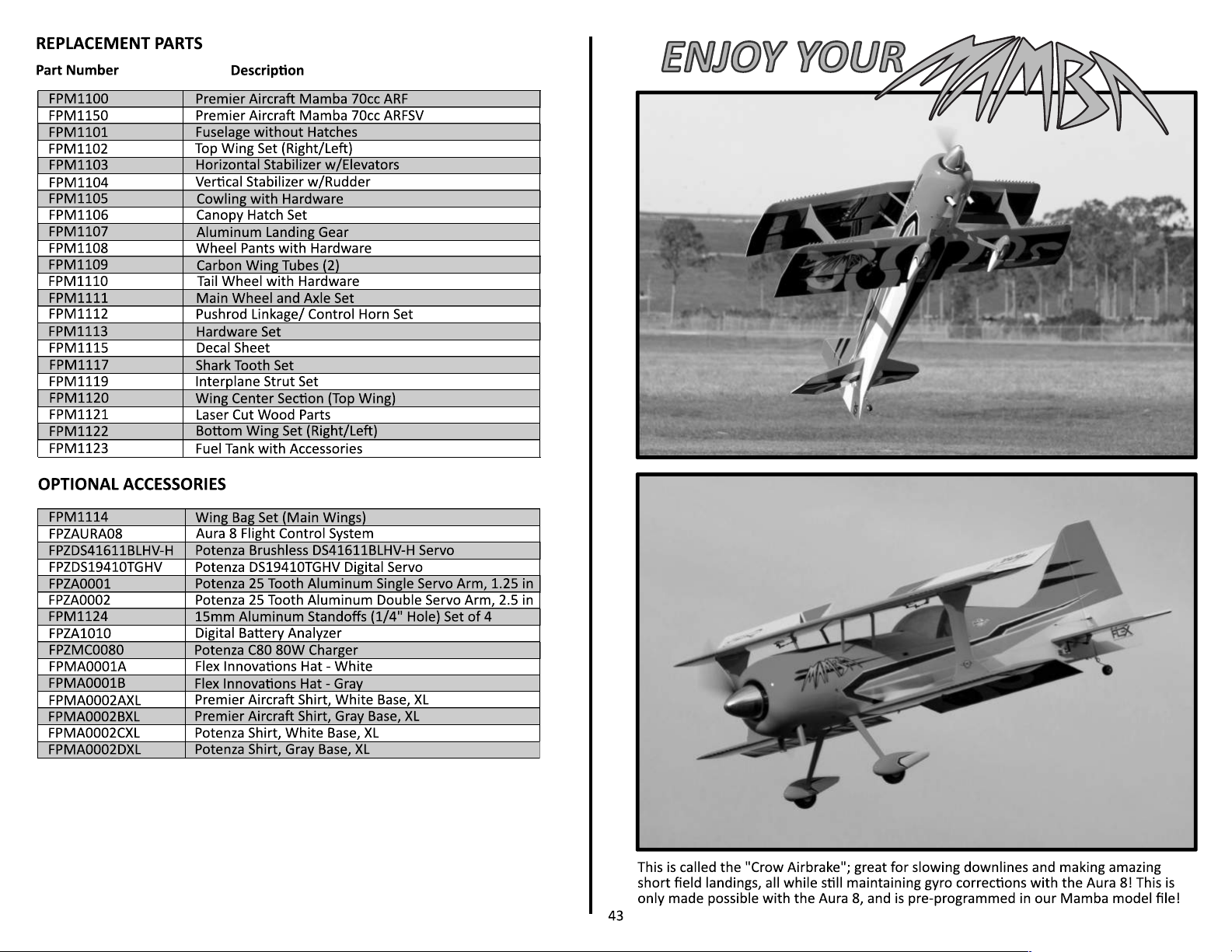
Page 45

LIMITED WARRANTY
Warranty Coverage
Flex Innovaons, Inc. and its authorized resellers ("Flex") warrant to the original
purchaser that the product purchased (the "Product") it wil be free from defects in
materials and workmanship at the date of purchase.
Law
These terms are governed by Florida law (without regard to conict of law principals).
This warranty gives you specic legal rights, and you may also have other rights which
vary from state to state. FLEX RESERVES THE RIGHT TO MODIFY THIS WARRANTY AT
ANY TIME WITHOUT PRIOR NOTICE.
Outside of Coverage
The warranty is not transferable and does not cover:
(a)
(b)
(c)
(d)
(e)
(f)
OTHER THAN THE EXPRESS WARRANTY ABOVE, FLEX MAKES NO OTHER WARRANTY
OR REPRESENTATION, AND HEREBY DISCLAIMS ANY AND ALL IMPLIED WARRANTIES,
INCLUDING, WITHOUT LIMITATION, THE IMPLIED WARRANTIES OF
NONINFRINGEMENT, MERCHANTABILITY AND FITNESS FOR A PARTICULAR PURPOSE.
THE PURCHASER ACKNOWLEDGES THAT THEY ALONE HAVE DETERMINED THAT THE
PRODUCT WILL SUITABLY MEET THE REQUIREMENTS OF THE PURCHASER'S
INTENDED USE.
Purchaser's Solu�on
Flex's sole obligaon and purchaser's sole and exclusive remedy shall be that Flex will,
at its opon, either (i) service, or (ii) replace, any Product determined by Flex to be
defecve. Flex reserves the right to inspect any and all Product(s) involved in a
warranty claim. Service or replacement decisions are at the sole discreon of Flex.
Proof of purchase is required for all warranty claims. SERVICE OR REPLACEMENT AS
PROVIDED UNDER THIS WARRANTY IS THE PURCHASER'S SOLE AND EXCLUSIVE
REMEDY.
Products with more than 45 days aer purchased date.
Damage due to acts of God, accident, misuse, abuse, negligence, commercial
use, or due to improper use, installaon, operaon or maintenance.
Modicaon of or to any part of the Product.
Product not compliant with applicable technical regulaons.
Shipping damage.
Cosmec damage.
Ques�ons & Assistance
Contact Us By:
E-Mail - support@exinnvaons.com
Phone - 1 (866) 310-3539
Inspec�on or Services
If this Product needs to be inspected or serviced and is compliant in the region you
live and use the Product in, please contact your regional Flex authorized reseller. Pack
the Product securely using a shipping carton. Please note that original boxes need to
be included, but are not designed to withstand the rigors of shipping without
addional protecon. Ship via a carrier that provides tracking and insurance for lost
or damaged parcels, as Flex is not responsible for merchandise unl it arrives and is
accepted at our facility.
Warranty Requirements
For Warranty consideraon, you must include your original sales receipt verifying the
proof of purchase date. Provided any warranty condions have been met, your
Product will be replaced free of charge. Shipping charges are as follows: to Flex by
customer, Flex out is by Flex. Service or replacement decisions are at the sole
discreon of Flex.
Limita�on of Liability
FLEX SHALL NOT BE LIABLE FOR SPECIAL, INDIRECT, INCIDENTAL OR CONSEQUENTIAL
DAMAGES, LOSS OF PROFITS OR PRODUCTION OR COMMERCIAL LOSS IN ANY WAY,
REGARDLESS OF WHETHER SUCH CLAIMS IS BASED IN CONTRACT, WARRANTY, TORT,
NEGLIGENCE, STRICT LIABILITY OR ANY OTHER THEORY OF LIABILITY, EVEN IF FLEX
HAS BEEN ADVISED OF THE POSSIBILITY OF SUCH DAMAGES.
Further, in no event shall the liability of Flex exceed the individual price of product on
which liability is asserted. As Flex has no control over use, setup, assembly,
modicaon or misuse, no liability shall be assumed nor accepted for any resulng
damage or injury. By the act of use, setup or assembly, the user accepts all resulng
liability. If you as the purchaser or user are not prepared to accept the liability
associated with the use of the Product, purchaser is advised to return the Product
immediately in new and unused condion to the place of purchase.
44
Page 46
(a)
(b)
(a)
(b)
(c)
(d)
(e)
(f)
(g)
(h)
(i)
1.
2.
Excepons:
Free Flight fuses or devices that burn producing smoke and are securely aached to the model aircra
during ight.
Rocket motors (using solid propellant) up to a G-series size may be used provided they remain aached to
the model during ight. Model rockets may be own in accordance with the Naonal Model Rocketry Safety
Code but may not be launched from model aircra.
Ocially designated AMA Air Show Teams (AST) are authorized to use devices and pracces as dened
within the Team AMA Program Document. (AMA Document #718.)
(j)
Not operate a turbine-powered aircra, unless in compliance with the AMA turbine regulaons. (AMA
Document #510-A.)
3.
Model aircra will not be own in AMA sanconed events, air shows, or model demonstraons unless:
The aircra, control system and pilot skills have successfully demonstrated all maneuvers intended or
ancipated prior to the specic event.
An inexperienced pilot is assisted by an experienced pilot.
When and where required by rule, helmets must be properly worn and fastened. They must be OSHA, DOT,
ANSI, SNELL or NOCSAE approved or comply with comparable standards.
(a)
(b)
4.
A.
B.
RADIO CONTROL (RC)
1.
All pilots shall avoid ying directly over unprotected people, vessels, vehicles or structures and shall avoid
endangerment of life and property of others.
A successful radio equipment ground-range check in accordance with manufacturer's recommendaons will be
completed before the rst ight of a new or repaired model aircra.
At all ying sites a safety line(s) must be established in front of which all ying takes place. (AMA Document
#706)
Only personnel associated with ying the model aircra are allowed at or in front of the safety
line.
At airshows or demonstraons, a straight safety line must be established.
2.
3.
(a)
(b)
Academy of Model Aeronaucs Naonal Model Aircra Safety Code
Eecve January 1, 2015
If you are not an AMA member, please consider joining. Founded in 1936 and open to
anyone interested in model aviaon, the AMA is the governing body for model aviaon in
the United States and sancons over 2,000 compeons anually.
Membership in the AMA provides liability insurance coverage, protects modelers' rights
and interests, and is required to y at most of the 2,700+ R/C sites naonwide.
Academy of Model Aeronaucs
5161 East Memorial Drive
Muncie, IN 47302-9252
Toll Free (800) 435-9262
Fax (765) 741-0057
www.modelaircra.org
An area away from the safety line must be maintained for spectators.
Intenonal ying behind the safety line is prohibited.
RC model aircra must use the radio-control frequencies currently allowed by the Federal Communica
GENERAL: A model aircra is a non-human-carrying aircra capable of sustained ght in the
atmosphere. It may not exceed limitaons of this code and is intended exclusively for sport,
recreaon, educaon and/or compeon. All model ghts must be conducted in accordance with
this safety code and any addional rules specic to the ying site.
Model aircra will not be own:
In a careless or reckless manner.
At a locaon where model aircra acvies are prohibited.
Model aircra pilots will:
Yield the right of way to all human-carrying aircra.
See and avoid all aircra and a spoer must be used when appropriate.
(AMA Document #540-D.)
Not y higher than approximately 400 feet above ground level within three (3) miles of an
airport without nofying the airport operator.
Not interfere with operaons and trac paerns at any airport, heliport or seaplane base
except where there is a mixed use agreement.
Not exceed a takeo weight, including fuel, of 55 pounds unless in compliance with the AMA
Large Model Airplane program. (AMA Document 520-A.)
Ensure the aircra is idened with the name and address or AMA number of the owner on the
inside or axed to the outside of the model aircra. (This does not apply to model aircra own
indoors.)
Not operate aircra with metal-blade propellers or with gaseous boosts except for helicopters
operated under the provisions of AMA Document #555.
Not operate model aircra while under the inuence of alcohol or while using any drug that
could adversely aect the pilot’s ability to safely control the model.
Not operate model aircra carrying pyrotechnic devices that explode or burn, or any device
which propels a projecle or drops any object that creates hazard to persons or property
4.
Commission (FCC). Only individuals properly licensed by the FCC are authorized to operate equipment on
Amateur Band frequencies.
RC model aircra will not knowingly operate within three (3) miles of any pre-exisng ying site without a
5.
frequency-management agreement. (AMA Documents #922 and #923.)
With the excepon of events own under ocial AMA Compeon Regulaons, excluding takeo and landing,
6.
no powered model may be own outdoors closer than 25 feet to any individual, except for the pilot and the
pilot's helper(s) located at the ightline.
Under no circumstances may a pilot or other person touch an outdoor model aircra in ight while it is sll
under power, except to divert it from striking an individual.
7.
RC night ying requires a lighng system providing the pilot with a clear view of the model's atude and
orientaon at all mes. Hand-held illuminaon systems are inadequate for night ying operaons.
8.
The pilot of an RC model aircra shall:
Maintain control during the enre ight, maintaining visual contact without enhancement other
9.
than by correcve lenses prescribed for the pilot.
Fly using the assistance of a camera or First-Person-View (FPV) only in accordance with the
procedures outlined in AMA Document #550.
Fly using the assistance of autopilot or stabilizaon system only in accordance with the
procedures outlined in AMA Document #560.
C. FREE FLIGHT
Must be at least 100 feet downwind of spectators and automobile parking when the model
1.
aircra is launched.
Launch area must be clear of all individuals except mechanics, ocials, and other iers.
2.
An eecve device will be used to exnguish any fuse on the model aircra aer the fuse has
3.
completed its funcon.
D. CONTROL LINE
The complete control system (including the safety thong where applicable) must have an
1.
inspecon and pull test prior to ying.
The pull test will be in accordance with the current Compeon Regulaons for the applicable
2.
model aircra category.
Model aircra not ng a specic category shall use those pull-test requirements as indicated
3.
for Control Line Precision Aerobacs.
The ying area must be clear of all ulity wires or poles and a model aircra will not be own
4.
closer than 50 feet to any above-ground electric ulity lines.
The ying area must be clear of all nonessenal parcipants and spectators before the engine is
started.
5.
ons
45
Page 47

BUILDING AND FLYING NOTES
46
Page 48

BUILDING AND FLYING NOTES
47
Page 49

 Loading...