

Page 1
Instruction Manual
ARF and ARFSV
Page 2

BEFORE CONTINUING WITH THIS INSTRUCTION MANUAL OR THE ASSEMBLY OF YOUR
AIRCRAFT, PLEASE VISIT OUR WIKI SUPPORT SITE FOR THE LATEST PRODUCT UPDATES,
FEATURE CHANGES AND MANUAL ADDENDUMS FOR THIS PRODUCT.
wiki.flexinnovations.com/wiki/Cap_232EX_70cc
Page 3

TABLE OF CONTENTS
Introduction .............................................................................................................................. 1
Specifications: ................................................................................................................................................................. 2
Required Equipment: ................................................................................................................................................... 2
Optional Equipment: .................................................................................................................................................... 3
Ultracote®/Oracover® Colors: ..................................................................................................................................... 3
Using this Manual ............................................................................................................................ 4
ARF .............................................................................................................................................. 6
Aileron and Elevator Control Horn Installation ......................................................................... 6
Control Horn Installation ............................................................................................................................................ 6
Aileron Servo and Linkage Installation ....................................................................................... 8
Elevator Servo and Linkage Installation ................................................................................... 10
ARF and ARFSV ....................................................................................................................... 14
Rudder and Tailwheel Installation ............................................................................................. 14
Landing Gear Installation ............................................................................................................. 16
Gas Power Setup .................................................................................................................... 19
DA-70 Engine Installation ............................................................................................................ 19
DA-70 Throttle Servo and Linkage Installation ................................................................................................ 20
Ignition Installation ....................................................................................................................... 23
Fuel Tank Installation .................................................................................................................... 25
Exhaust and Cowling Installation ............................................................................................... 27
Muffler Installation (A) .............................................................................................................................................. 28
Canister Installation (B) ............................................................................................................................................. 30
Engine Baffling Installation ..................................................................................................................................... 33
Cowling, Propeller and Spinner Final Installation ................................................................... 36
Electric Power Setup ............................................................................................................. 39
Motor Installation .......................................................................................................................... 39
ESC Installation .............................................................................................................................. 40
Battery Tray Installation ............................................................................................................... 41
Motor/ESC Cooling ........................................................................................................................ 43
Rudder Servo and Control Horn Installation ............................................................................ 44
Push-Pull Rudder Setup ............................................................................................................................................ 46
Pull-Pull Rudder Setup .............................................................................................................................................. 47
Mounting the Stab ........................................................................................................................ 50
Radio Installation ........................................................................................................................... 52
Install the Wing Fairing ................................................................................................................. 54
Field Assembly ............................................................................................................................... 56
Side Force Generators Installation (optional) ................................................................................................... 59
Page 4

Decal Installation ........................................................................................................................... 59
Final Setup and Flying Notes ............................................................................................... 61
Center of Gravity ............................................................................................................................ 61
Aura 8 Professional ........................................................................................................................ 62
Range Testing ................................................................................................................................. 63
Before First Flight .......................................................................................................................... 63
AMA Safety Code ........................................................................................................................... 64
Replacement Parts ......................................................................................................................... 65
Optional Accessories ..................................................................................................................... 66
Limited Warranty ................................................................................................................... 67
Page 5
Cap 232EX 70cc Instruction Manual
INTRODUCTION
The Mudry Cap 232EX rose to fame as an iconic full scale aerobatic airplane flown in aerobatic
competitions in the late 1990’s. Designed by World Champion Quique Somenzini, the Cap 232EX
70cc redefines what a Cap 232EX 70cc can be as a model airplane: an absolute aerobatic monster,
with full-scale presence, all while addressing the undesirable behaviors previously associated with
scale Cap 232’s. Beyond its impressive show-time presence, the Cap 232EX 70cc offers a wide flight
envelope which excels at high energy XA maneuvers, 3D slow and stable characteristics, and
precision flight.
To manage the highest G loads demanded by XA aerobatics, the Cap 232EX 70cc uses the latest in
modern building techniques and materials, including black fiber, fiberglass, and laminated plywood,
creating a lightweight, yet rigid airframe that can handle your wildest aerobatic aspirations. The Cap
232EX 70cc features proprietary Flex Innovations Speed-Lock’s on the wings, stabilizers, and canopy,
allowing you to assemble the airplane without the need for screws or tools! Additionally, all Cap
232EX 70cc’s come pre-hinged and gap sealed from the factory! The ARFSV version adds FACTORYINSTALLED Flex DS49010BLHV servos, G-10 control horns, metal clamping servo arms and premade
linkages to get you in the air even faster! The Cap 232EX 70cc is available in two distinctive color
schemes by Clint Sweet Designs, perfectly marrying the aircraft’s looks with its high-performance
capabilities. The Cap 232EX 70cc represents the pinnacle of what you can expect from Flex
Innovations: World Championship Performance with Authentic Scale Looks!
Happy flying!
1
Page 6

Cap 232EX 70cc Instruction Manual
Wingspan:
88 in. (2235mm)
Length:
91.7 in. (2330mm) including spinner
Estimated Weight:
(DA-70 w/standard muffler)
20.4 lb. (9.3kg)
Engine Size:
70-76cc
Transmitter:
8+ channels
Receiver:
8+ channels, high-voltage capable
Receiver Battery:
(2) 2S 2000mAh 15C+ LiPos (FPZBR20002S15 recommended)
Recommended Servos:
(5) Minimum 450 oz/in (32.4 kg/cm) for control surfaces & (1)
standard servo for throttle.
(6) Potenza DS49010BLHV Servos
(FPZDS49010BLHV) recommended
Aileron, Elevator & Rudder:
(5) Potenza 2-inch Clamping Servo Arm
(FPZA1036 or FPZA1036B) recommended
Ailerons:
(2) 9-inch (230mm) FPZA1044
Elevators:
(2) 36-inch (920 mm) FPZ1048
Rudder:
Tail-Mounted Push-Pull – (1) 36-inch (920 mm) FPZA1048
Forward-Mounted Pull-Pull – None Required
Throttle:
(1) 9-inch (230cm) FPZA1044
Spinner:
4-inch (101 mm)
Flex Innovations 4-inch Carbon Fiber Spinner, Edge Style
(FPMA1031 & FPMA1032) recommended
Specifications:
Required Equipment:
Radio Equipment & Servos:
Servo Arms:
Servo Extensions:
Spinner:
2
Page 7

Cap 232EX 70cc Instruction Manual
Engine:
70-76cc Two-Stroke Engine Desert Aircraft DA-70 recommended
Exhaust:
Follow your engine manufacturer’s recommendation, as well as local
noise restrictions in your area.
Desert Aircraft Stock Muffler Set (FPMDA70MUFFLER) recommended
Other Exhaust Options:
MTW TDH110 (Rear Exit)
90mm drop Y header
Propeller:
Follow your engine manufacturer’s recommendation.
FLEX 24 x 9 recommended for the DA-70 on stock mufflers
Engine Standoffs:
(4) 15 mm Aluminum Engine Standoffs (FPM1124) recommended
Ignition Regulator:
Follow your engine manufacturer’s recommendation
Ignition Battery
Follow the manufacturer’s voltage requirements.
2S 2000mAh 15C+ Li-Po (FPZBR20002S15) recommended
Fuel Dot:
McFueler Fuel Dot (FPMAMCFUELER)
FPZAURA08PRO
Aura 8 Professional
FPM2019
700cc Lightweight Fuel/Smoke Tank (for smoke)
FPMHOLYG2
Holy Smokes G2 Smoke System
FPM2314
Flex Innovations Premium Wing and Tail Bag Set
FPM2327A
FPM227B
Cap 232EX 70cc Pilot and Cockpit Set, Red
Cap 232EX 70cc Pilot and Cockpit Set, Yellow
FPM2329A
FPM2329B
Cap 232EX 70cc Premium Decal Set Red Scheme
Cap 232EX 70cc Premium Decal Set Yellow Scheme
FPMA1033
Flex Aircraft Sunshade 70cc Monoplane
Ultracote®
Oracover®
True Red (HANU866)
Ferrari Red (21-023)
Black (HANU874)
Black (21-071)
White (HANU870)
White (21-010)
Ultracote®
Oracover®
Dark Yellow (HANU889
Golden Yellow (21-032)
Midnight Blue (HANU885)
Dark Blue (21-052)
White (HANU870)
White (21-010)
Gas Engine Setup
Optional Equipment:
Ultracote®/Oracover® Colors:
RED Scheme:
Yellow Scheme:
3
Page 8

Cap 232EX 70cc Instruction Manual
USING THIS MANUAL
The manual is divided into sections to make the assembly of the airplane easier to follow.
Note: The squares “▢” next to each step that can be checked off to help you keep track of the steps
that have been completed.
ATTENTION
Read the ENTIRE instruction manual to become familiar with the features and assembly of the
product before starting assembly. Failure to assemble or operate the product correctly can result in
damage to the product, personal property and cause serious or fatal injury.
All instructions, warranties and other collateral documents are subject to change at the sole
discretion of Flex Innovations, LLC. For up-to-date product literature, please visit our website at
www.flexinnovations.com and navigate to the product page for this product.
WARNING
This is NOT a toy. This product is not intended for use by children under 14 years of age
without direct adult supervision.
IMPORTANT INFORMATION REGARDING WARRANTY
Please read our Warranty and Liability section before building this product. If you as the purchaser or
user are not prepared to accept the liability associated with the use of this product, you are advised
to return this product immediately in new and unused condition, in the original packaging material,
to the place of purchase.
SAFETY WARNINGS AND PRECAUTIONS
Protect yourself and others by following these basic safety guidelines.
1. This manual contains instructions for safety, operation, and maintenance. It is essential to
read and follow all the instructions in the manual, prior to assembly, setup, or use, in order to
operate correctly and avoid damage or serious injury.
2. In some cases, the written instructions may differ slightly from the photos. In those instances,
the written instructions should be considered correct.
3. This model is not a toy, rather it is a sophisticated remote control hobby product and must be
operated with caution and common sense. This product requires some basic mechanical
ability. Failure to operate this product in a safe and responsible manner could result in injury,
or damage to the product, or other property.
4. This model must be assembled according to these instructions. Do not alter or modify the
model outside of these instructions provided by Flex Innovations, LLC, as doing so may
render it unsafe and/or unflyable. You must take time to build straight, true, and strong. It is
your responsibility to ensure the air worthiness of this product.
5. Use only compatible, appropriate components for the final assembly of this model. Ensure
that the radio system is in functional condition, that the engine is appropriately sized for the
model and that all other components are appropriate for use in this model as specified in this
instruction manual. All components must be installed correctly so that they operate correctly
both on the ground and in the air.
6. Inspect and check the operation of the model and all its components before every flight.
4
Page 9

Cap 232EX 70cc Instruction Manual
7. If you are not an experienced pilot, or have not flown a high-performance model before, it is
recommended that you seek assistance from an experienced pilot in your R/C club for your
first flights. If you're not a member of a club, the Academy of Model Aeronautics (AMA) has
information about clubs in your area whose membership includes experienced pilots.
8. Keep the propeller area clear from such items as loose clothing, jewelry, long hair, or tools, as
they can become entangled. Keep your hands and body parts away from the propeller as
injury can occur.
SPECIAL LANGUAGE DEFINITIONS
The following terms are used throughout the product literature to indicate various levels of potential
harm when operating the product.
NOTICE: Procedures, which if not properly followed, create a possibility of physical
property damage AND a liable or no possibility of injury.
CAUTION: Procedures, which if not properly followed, create a probability of physical
property damage AND a possibility of serious injury.
WARNING: Procedures, which if not properly followed, create the probability of property
damage, collateral damage and serious injury OR create a high probability of
serious injury.
IMPORTANT BEFORE ASSEMBLY
Carefully unpack your aircraft and inspect the parts. Review the manual and gather the required tools
and supplies.
o Remove all parts from their plastic bags, inventory all items and closely examine all the major
airframe components for damage. If any items are missing or you find damaged components,
do not proceed. Please contact customer support.
o Use a covering iron with a covering sock on high heat to tighten the covering as necessary,
paying special attention to the leading edges of the flying surfaces, hinge lines and stabilizer
and wing saddle areas. Apply slight pressure over sheeted areas to thoroughly bond the
covering to the wood. Use caution around seams to prevent inadvertently pulling them loose.
o Pro-Tip: You can use a “Seal-It Pen” or clear nail polish to permanently seal any sharp
edges or corners of covering that may come loose in flight.
o Use thin CA to go over any important glue joints, such as the motor box, firewall, servo
mounting rails and any other pre-assembled joints that may see high stress during flight.
o Gather all the required components such as motor and radio equipment that will be used to
equip the airplane. Create a new radio program in your transmitter and bind this model
program to the receiver that will be used in the airplane
5
Page 10
Cap 232EX 70cc Instruction Manual
Required for this section
Components
Tools
Adhesives/Building Materials
o Left and Right Wing Panels (2)
o Left and Right Horizontal
Stabilizers
o Aileron Control Horns (2 sets of 2)
o Elevator Control Horns (2 sets of 2)
o Aileron Control Horn Bases (2)
o Elevator Control Horn Bases (2)
Hobby Knife with a
#11 blade
o Isopropyl Alcohol
o 30-minute Epoxy
o Paper Towels
o Toothpicks
o Mixing Cups
o Mixing Sticks (something to
mix epoxy with)
!
ARF
If your airplane is the ARF version start building from this page through the end of this manual. If you
have the ARFSV version, please proceed from Page 14 through the end of this manual.
AILERON AND ELEVATOR CONTROL HORN INSTALLATION
Control Horn Installation
!
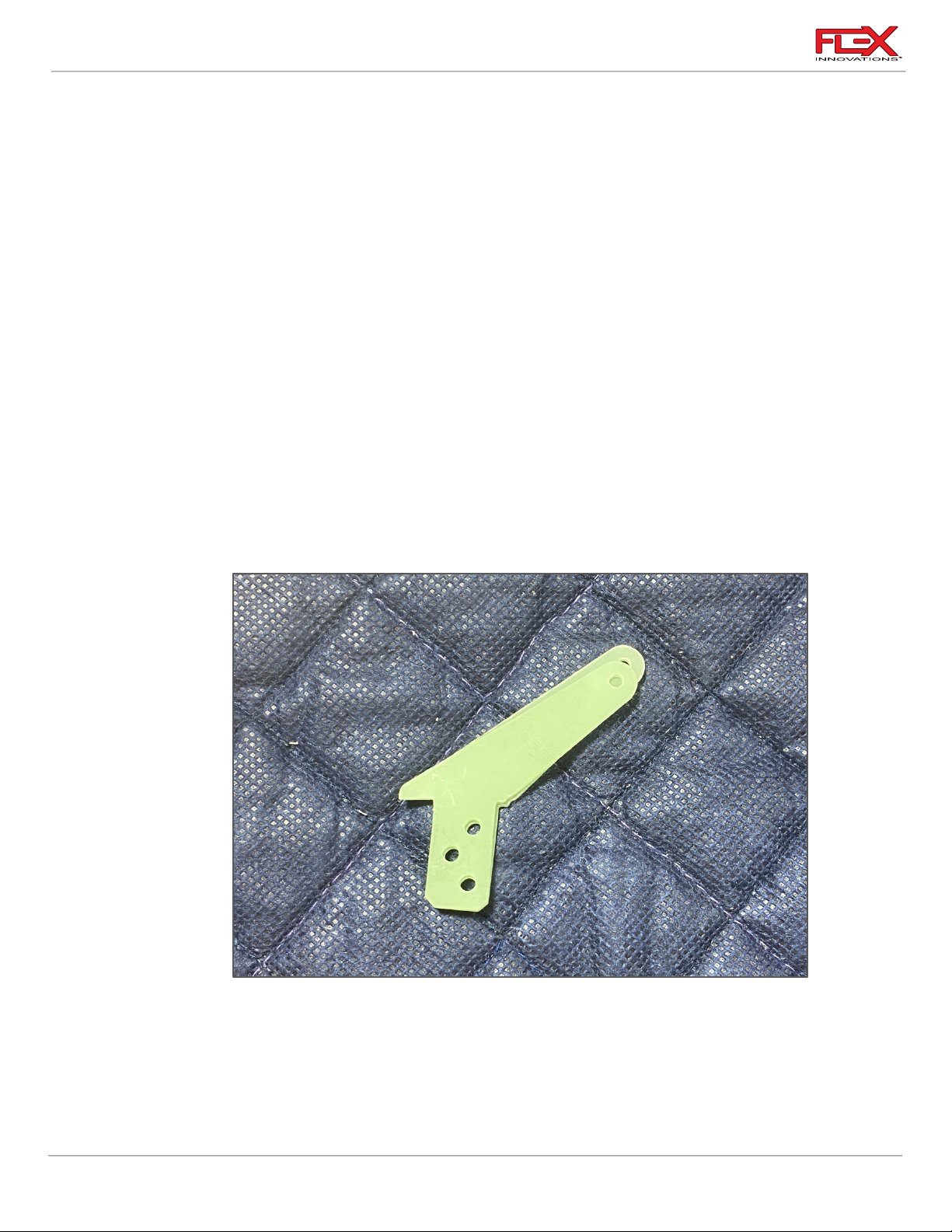
1. Locate the aileron and elevator control horns. Be sure to keep them identified and
separate.
6
Page 11
Cap 232EX 70cc Instruction Manual
!
!
!
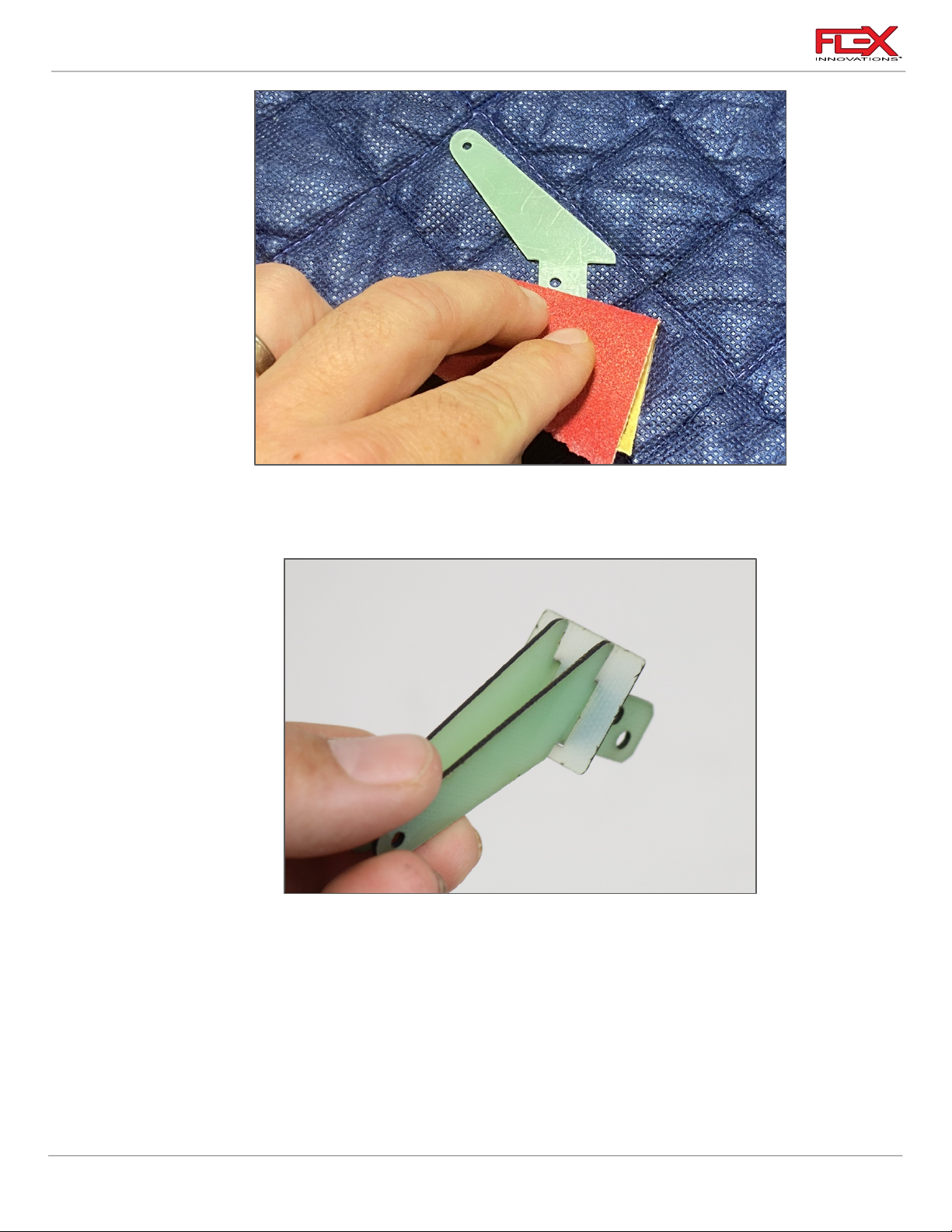
2. Scuff each control horn with medium grit sandpaper where it enters the control surface.
Use a paper towel and isopropyl alcohol to clean up the control horn after it has been
scuffed.
!
3. Slide the control horns through the square control horn base, and test fit them in their
corresponding slots. Note that the holes in the control horn base are offset. This is so that
the base does not extend over the hinge line. Adjust the holes in the control surfaces to
fit the control horns if needed.
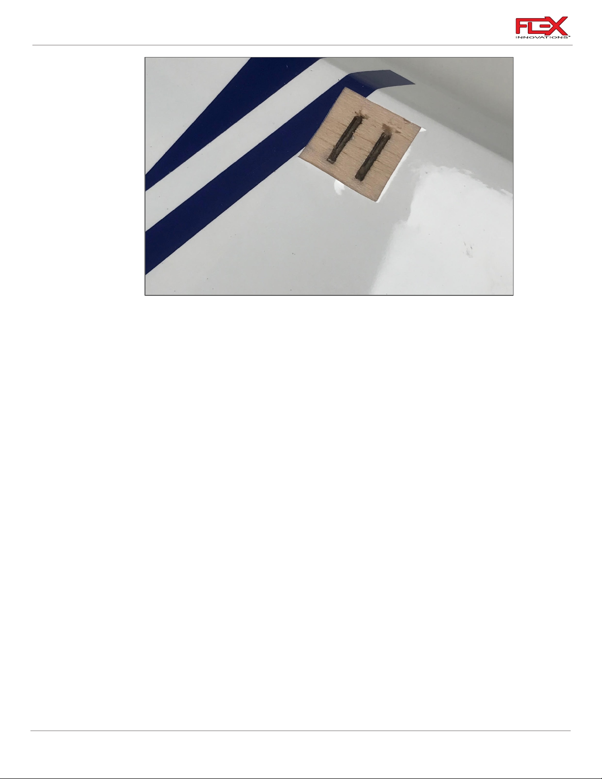
4. Mark around the square control base. Use a very sharp hobby knife to remove the
covering where the square will be bonded to the control surface. Ensure that you don’t
cut too deep to avoid damaging the control surface under the covering.
7
!
Page 12
Cap 232EX 70cc Instruction Manual
!
Required for this section
Components
Tools
Adhesives/Building Materials
o Main Wing Panels (2)
o Aileron Linkages (2)
o Aileron Servos (2)
o Aileron Servo Arms (2)
o Ball Links (4)
o M3 x 15 Socket Head Cap
Screw (2)
o M3 x 20 Socket Head Cap
Screw (2)
o M3 Washer (8)
o M3 Lock Nut (4)
o M3 Conical Spacer (2)
o 2.5mm Hex Driver
o 5.5mm Nut Driver
o #1 Phillips Screwdriver
o Thin CA
o Blue Thread Lock
o Heat shrink, dental floss or
safety clips
!
5. Apply 30-minute epoxy to the control horn slots and control horns and insert the control
horns into their corresponding slots. Use a paper towel and isopropyl alcohol to clean up
any excess epoxy. Set the parts aside and let the epoxy fully cure.
!
Quique’s Pro Tips:
• Use a ball link and the corresponding hardware to keep the two parts of each control horn
aligned while the epoxy cures.
AILERON SERVO AND LINKAGE INSTALLATION
1. Use a #1 Phillips screwdriver to thread a servo mounting screw into each of the pre-cut
holes in the servo mounting rails in the wing. Remove the screw and apply a small
8
Page 13

Cap 232EX 70cc Instruction Manual
!
!
!
!
!
!
amount of thin CA to each of the holes to harden the threads cut by the screw. Do not
use CA accelerator. Let the CA fully cure before moving forward.
2. Assemble your servo grommets per your servo manufacturer’s instructions.
Quique Pro Tip:
Many servo grommet brass eyelets will fit over most hex drivers. Slide all the eyelets over the hex
driver, flared end first. Use the hex driver to push the eyelets into the servo grommets one right after
the other for easier installation.
3. Secure a servo extension to each of the two tip aileron servos. Use servo connector safety
clips (FPZA1040), heat shrink or dental floss to secure the extension.
4. Insert the aileron servo into the servo bay with the output shaft towards the LEADING
EDGE of the wing. Be sure to route the servo lead out of the wing before mounting the
servo. Mount the servo to the wing using the servo mounting screws provided with your
servos.
5. Using an aileron pushrod, assemble the aileron linkages so that the total length from
center of ball to center of ball is approximately 3-5/8 inches (92mm). Final length will be
adjusted when centering the control surface. Note that one end of each aileron linkage
has left-hand threads, while the other end has right-hand threads.
Quique Pro Tip:
Use a set of digital calipers to measure the length of threads exposed on each end of the linkage. This
allows you to ensure that the ball links are equally threaded onto each end of the linkage.
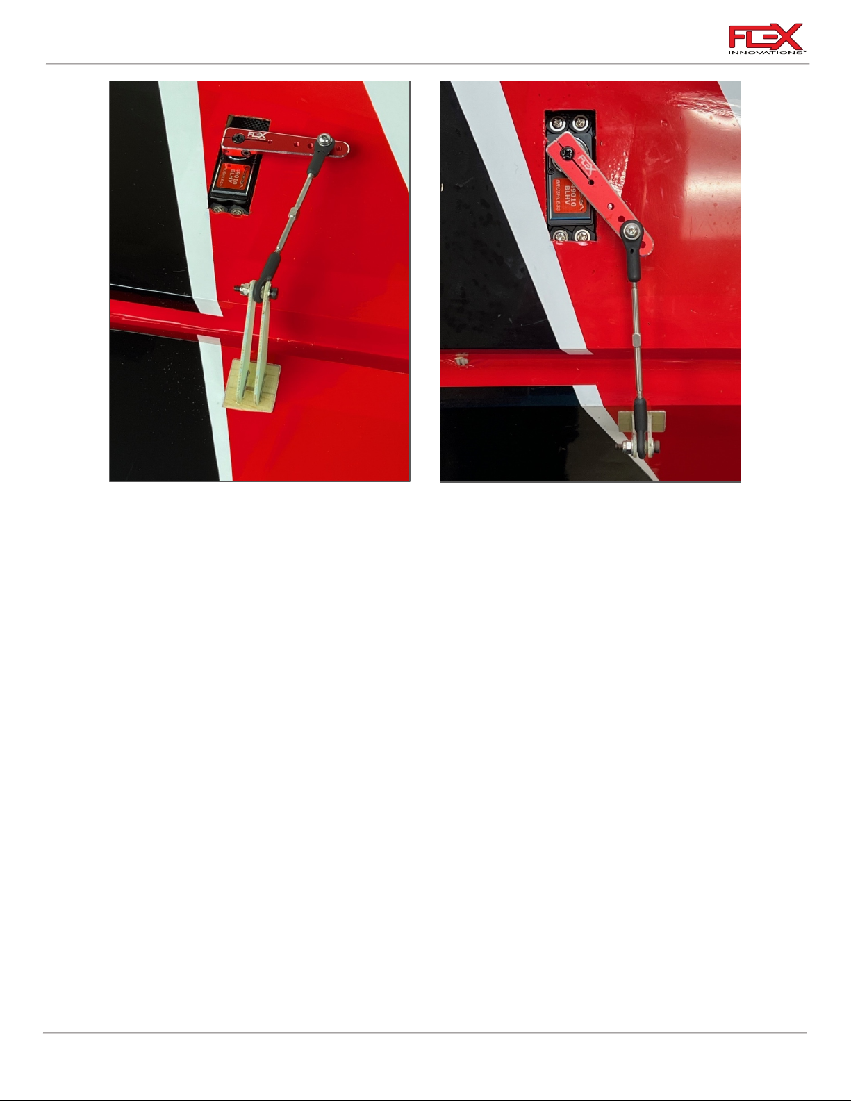
6. Attach the linkage to the servo arm. The correct hole location is 1 3/4-inches (44mm)
from center. If using the recommended 2-inch servo arm, this is the second hole from the
end of the servo arm. The order of hardware components, starting from the top of the
servo is as follows:
o M3x20 socket head cap screw
o M3 washer
o Ball Linkage
o Conical Spacer (narrow, pointed side towards the ball link)
o Servo Arm
o M3 washer
o M3 locknut
7. Use your radio system power on the servos to center them. Install your aileron servo arm
onto the servo as close to parallel with the hinge line as possible. Apply blue thread lock
to the servo arm output shaft screw and fully tighten the screw. If your servo arms have
clamping screws, apply blue thread lock, and secure them in place
Center the control surface by lengthening or shortening the linkage as needed.
9
Page 14
Cap 232EX 70cc Instruction Manual
Required for this section
Components
Tools
Adhesives/Building Materials
o Left and Right Horizontal
Stabilizers (2)
o Elevator Servos (2)
o Elevator Servo Arm (2)
o M3x15 Socket Head Cap
Screw (8)
o M3 Washer (8)
o M3 Lock Nut (4)
o M3 Conical Spacers (2)
o M3x10 Button Head Bolts(4)
o 2.5mm Hex Driver
o 5.5mm Nut Driver
o #1 Phillips Screwdriver
o Thin CA
o Blue Thread Lock
o Dental Floss, Heat Shrink or
Safety Clips
!
!
!
Note: The outward angle of the linkage when centered is correct. As the servo arm rotates and the
control surface deflects, the linkage will straighten.
ELEVATOR SERVO AND LINKAGE INSTALLATION
1. Use a #1 Phillips screwdriver to thread a servo mounting screw into each of the holes in
10
the servo mounting rails in the horizontal stabilizer. Remove the screw and apply a small
amount of thin CA to each of the holes to harden the threads cut by the screw. Do not
use kicker, allow the CA to fully cure before moving forward.
2. Assemble your servo grommets per your servo manufacturer's instructions.
Page 15
Cap 232EX 70cc Instruction Manual
!
!
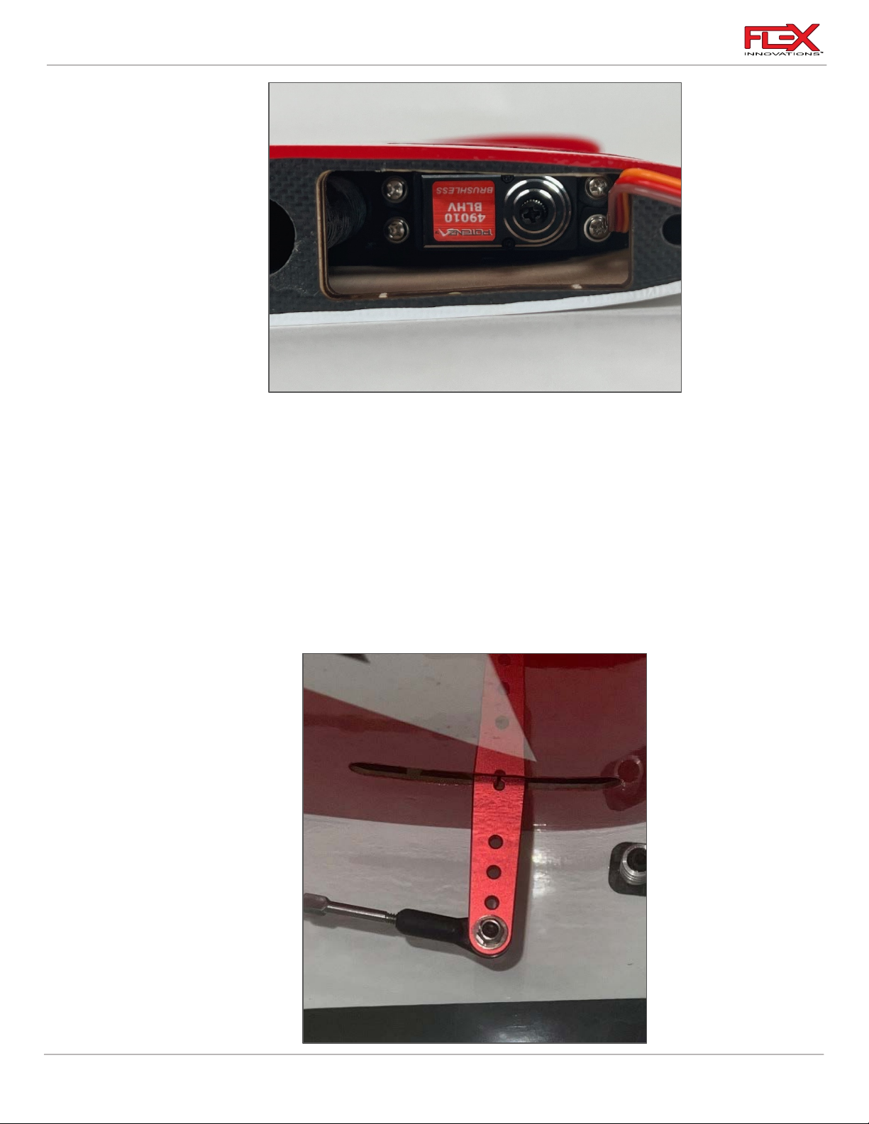
3. Insert the elevator servo into the mounting location with the output shaft towards the
leading-edge of the stab. Mount the servo to the stab using the mounting screws
provided with your servo. Note that the servo wire will exit on the leading-edge side of
the stab as shown in the picture above.
!
4. Power on your radio system to center the servo. Install a 2-inch (51mm) servo arm onto
the servo as close to perpendicular with the servo’s case as possible. Apply a small
amount of blue thread lock to the servo arm screw and secure it in place. If your servo
arm has clamping screws, apply blue thread lock to these screws and secure them in
place. Note that you may need to power off the model and rotate the servo arm by hand
to have access to each clamping screw. Use sub-trim to set the servo arm perfectly
perpendicular before installing the elevator.
11
!
Page 16

Cap 232EX 70cc Instruction Manual
!
!
!
!
5. Using an elevator pushrod, assemble the elevator linkages and ball links so that the total
length from center of ball to center of ball is approximately 3 ¼ in (83mm). Final length
will be adjusted when centering the control surface. Note that both ends of the elevator
linkages have opposite direction threads.
6. Attach the linkage to the servo arm. The correct hole location is 2-inches (50.8mm) from
the center of the servo. If you are using the recommended servo arm this is the hole at
the end of the servo extension arm. The order of hardware components, starting from the
top of the servo is as follows:
o M3x20 socket head cap screw
o M3 washer
o Ball Linkage
o Servo Arm
o M3 washer
o M3 locknut
Note: There is a conical spacer supplied with the elevator linkage hardware. If using the
recommended servo and servo arm, this spacer is not needed. If using a different brand
of servo or servo arm, you may need to use this spacer to keep the linkage perpendicular
to the hinge line. Most of the time, it is not needed.
7. Attach the linkage to the control horn. The order of hardware components, starting from
the tip of the stabilizer is as follows:
o M3x15 socket head cap screw
o M3 washer
o Control Horn #1
o Ball Linkage
o Control Horn #2
o M3 washer
o M3 locknut
8. With the radio powered on and the servo arm centered perpendicular to the servo case,
adjust the linkage length so that the control surface is centered.
Quique Pro Tip:
• For elevator centering, it is best to install the stabilizers onto the fuselage and stand
approximately 10 feet (3m) behind the aircraft while sighting the two elevator halves. Using
this method, you can best align the most important part of the control surface, the wider
section, rather than referencing something less important, like the elevator counterbalance.
12
Page 17
Cap 232EX 70cc Instruction Manual
!
!
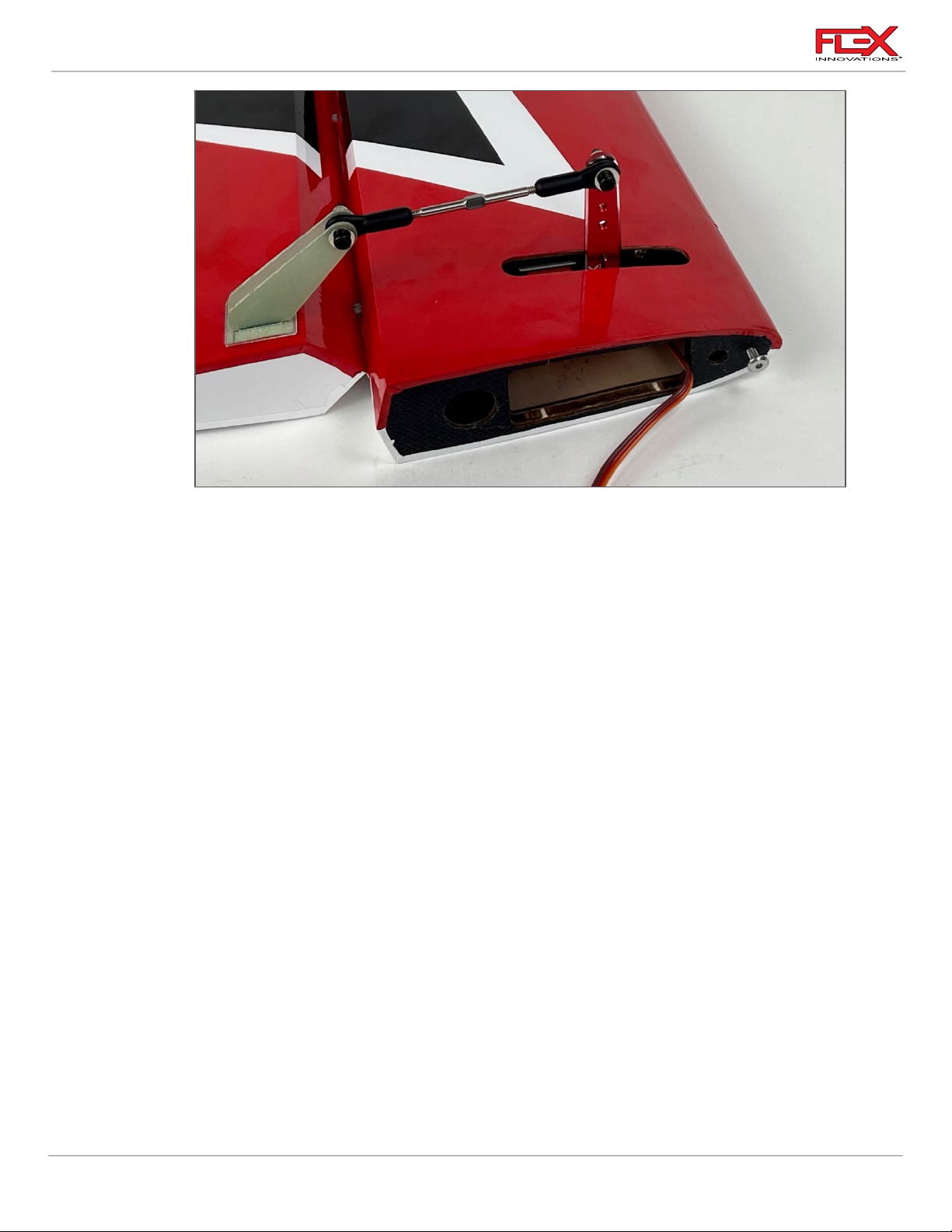
9. After installation is complete, your linkage setup should match the image above. Repeat
the same procedure for the other horizontal stabilizer.
13
Page 18
Cap 232EX 70cc Instruction Manual
Required for this section
Components
Tools
Adhesives/Building Materials
o Fuselage
o Tail Gear Assembly
o Steering Ball Link (1)
o M3 X16mm Washer (3)
Head Cap Screws (3)
o 2.5mm Hex Driver
o Blue Thread Lock
o Isopropyl Alcohol
o 30-minute Epoxy
o Mixing Cups
o Mixing Sticks
o Paper Towels
!
ARF AND ARFSV
If your airplane is an ARFSV you can start from this page.
RUDDER AND TAILWHEEL INSTALLATION
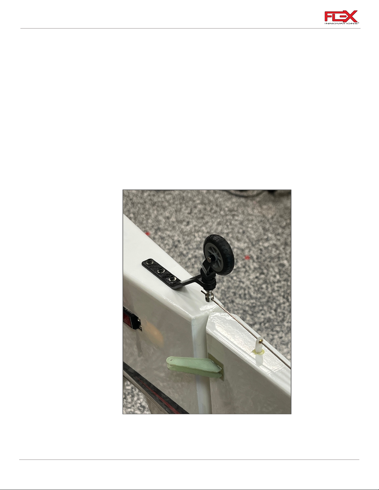
1. Apply Thread Lock to the screws and use a 2.5mm hex driver to mount the tail gear
14
assembly as shown in picture above.
!
Page 19
Cap 232EX 70cc Instruction Manual
!
!
!
2. Install the rudder using the rudder hinge wire. Install it from the top of the rudder and
slide the wire through the rudder hinge halves while holding the rudder in position.
!
3. Locate the hole in the bottom of the rudder that will accept the ball link for the steering
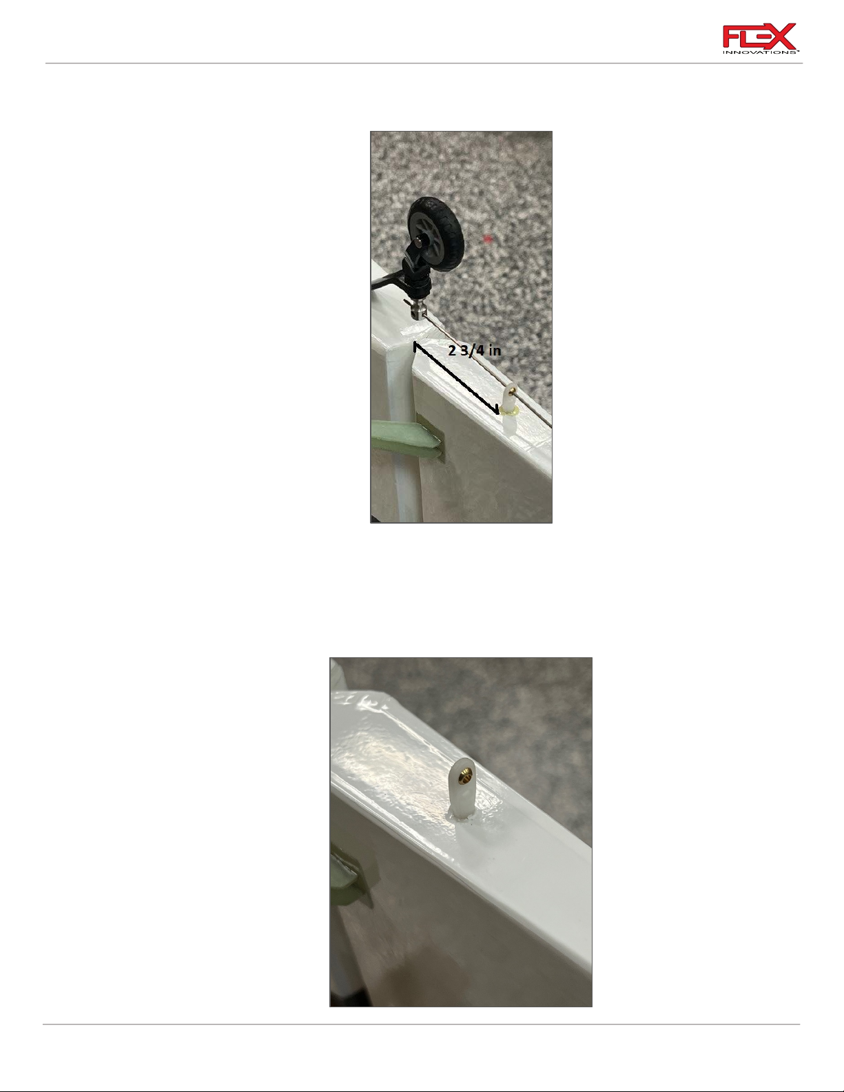
arm. It is located approximately 2-3/4 inches (70mm) aft of the rudder hinge line. Use a
hobby knife with a #11 blade to remove the covering from the hole.
4. Scuff the cylindrical part of the ball link with a medium grit sandpaper. Clean the ball link
with isopropyl alcohol and a paper towel to remove any leftover plastic particles.
15
!
Page 20
Cap 232EX 70cc Instruction Manual
!
!
Required for this section
Components
Tools
Adhesives/Building Materials
o Fuselage Assembly
o Landing Gear
o Wheel Pants (L & R)
o Main Wheel (2)
o M4x30 Socket Head Cap
Screw (4)
o M4 Flat Washer (8)
o M4 Lock Nut (4)
o M3x15 Socket Head Cap
Screw (4)
o M3 Flat Washer (4)
o Landing Gear Axle (2)
o M5 Wheel Collar (4)
o 1.5mm Hex Driver
o 2.5mm Hex Driver
o 3mm Hex Driver
o 7mm Wrench
o 10mm Wrench
o 12mm Wrench
o Felt-Tipped Pen
o Blue Thread Lock
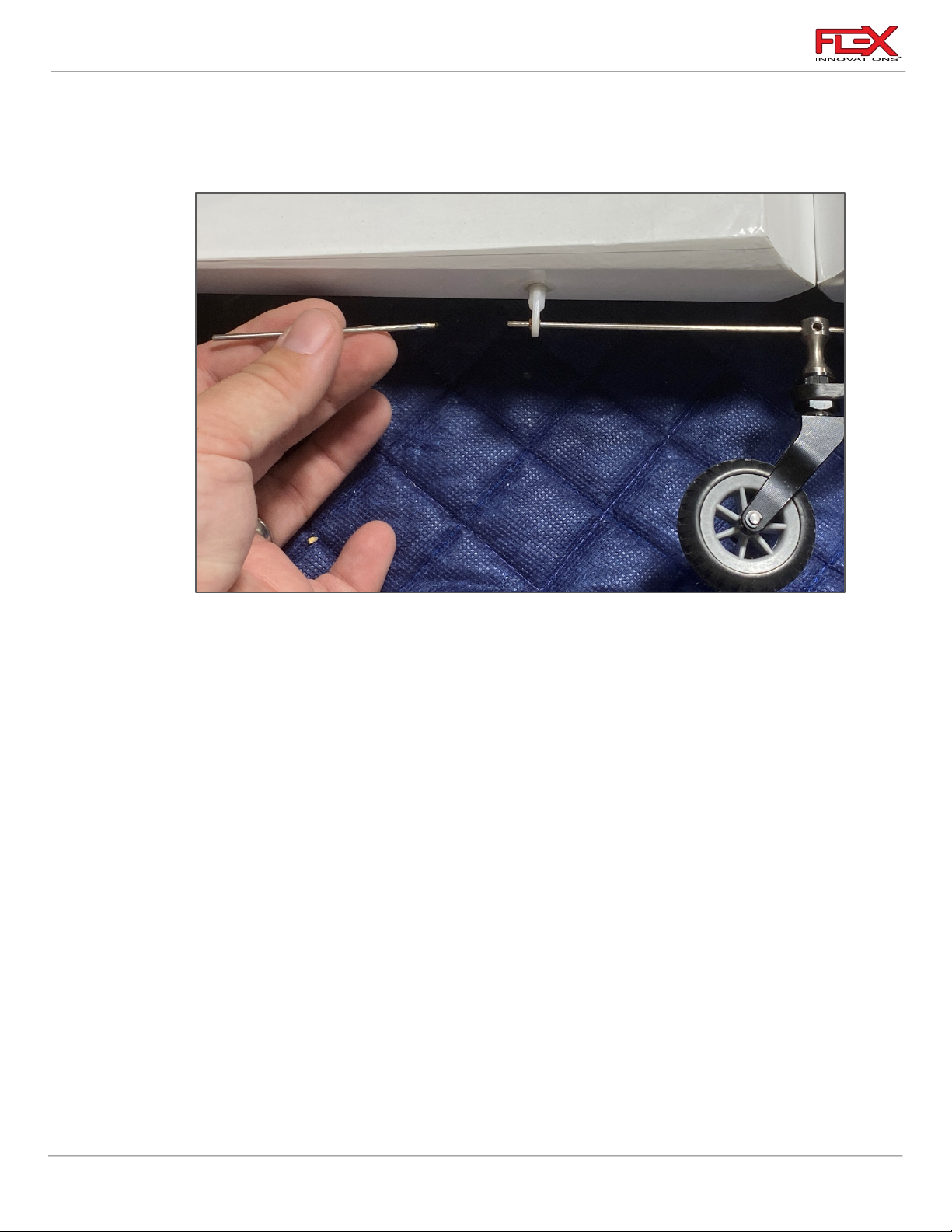
5. Once clean and dry, slide the wire steering arm through the ball link. Mix a small amount
of 30-minute epoxy and glue the steering ball link into the hole, being sure to keep the
ball link square to the bottom of the rudder, as well as perpendicular to the wire steering
arm. Allow a small fillet of epoxy around the ball link for added strength.
6. Once the epoxy has cured, trim the steering wire allowing for approximately 5/16-inch
(8mm) of excess wire to extend past the ball link. Once complete, rotate the rudder to
ensure everything moves freely without binding.
LANDING GEAR INSTALLATION
16
!
Page 21
Cap 232EX 70cc Instruction Manual
!
!
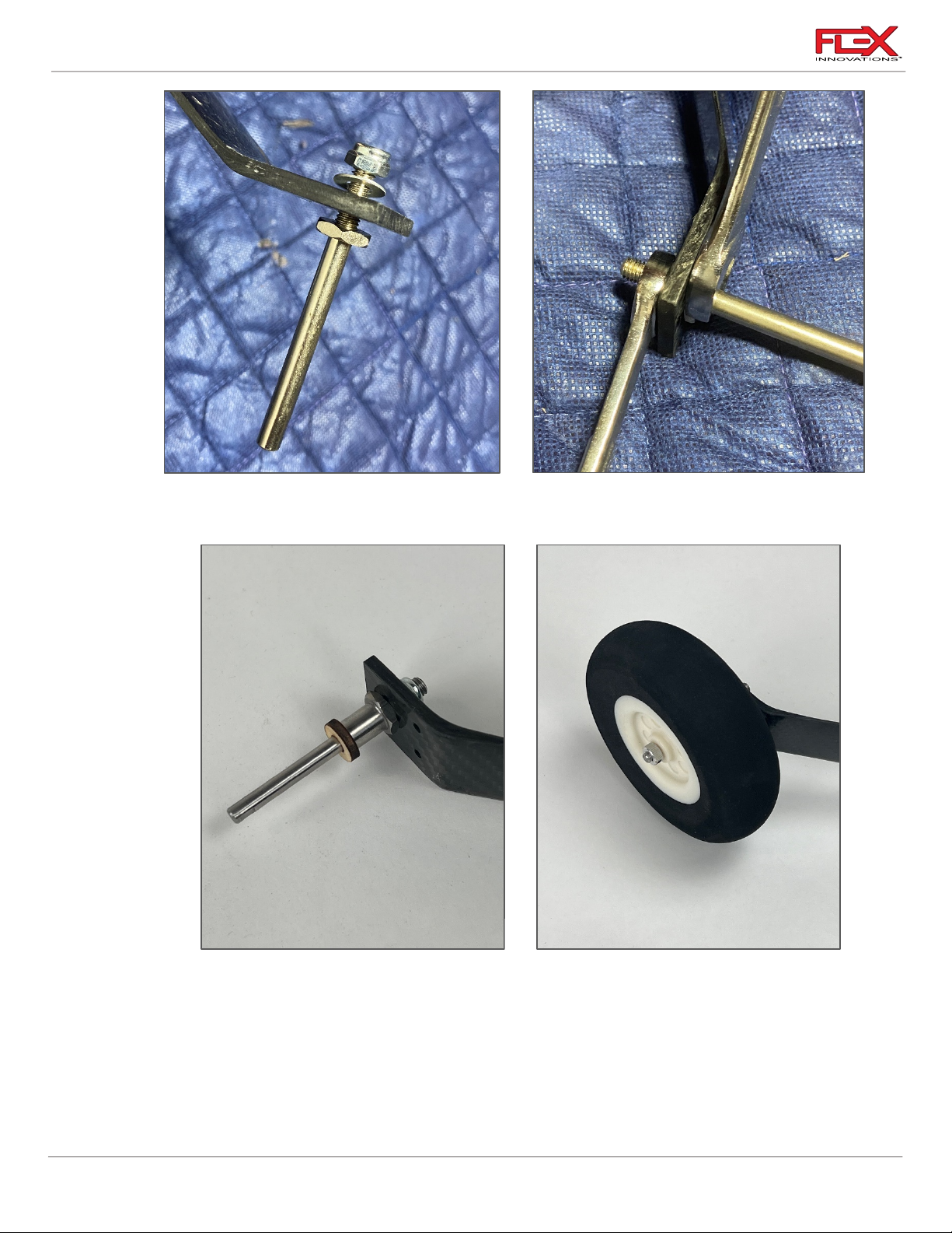
1. Assemble the axle to the landing gear leg. Use one M6 flat washer between the lock nut
and the landing gear leg as shown above. Fully tighten using a 10mm and 12mm wrench.
!
2. Slide the 3mm plywood washer to offer the correct spacing for the wheel pant. Next to
the plywood, slide an M5 wheel collar onto the axle with the shoulder facing the wheel.
Using blue thread lock and a 1.5mm driver, secure the set screw for the wheel collar in
place. Apply a small amount of oil to the axle and slide the wheel into place. Slide the
remaining M5 wheel collar onto the axle with the shoulder facing the wheel and use blue
thread lock when securing the set screw in place.
17
!
Page 22
Cap 232EX 70cc Instruction Manual
!
!
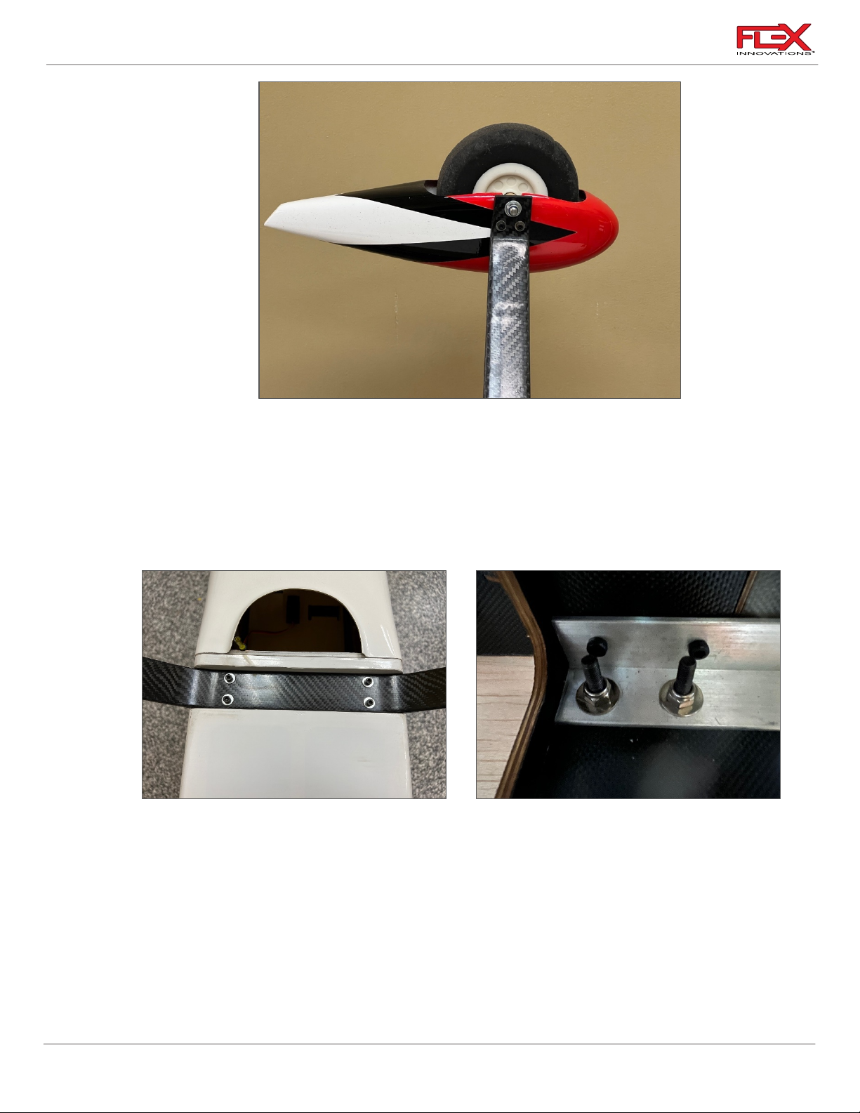
3. Using blue thread lock, secure the wheel pants in place using 2 M3 x 15 socket head cap
screws and 2 M3 washers using a 2.5mm hex wrench.
!
Quique Pro Tip:
To help prevent damage to the wheel pants, leave the wheel pants off the aircraft until you have
completed the aircraft and are ready to check the center of gravity. You can thread the wheel pant
mounting screws into the wheel pants to save everything for later without losing the hardware.
4. Place the landing gear on the fuselage so that it sweeps forward and the wheels are
closer to the nose of the airplane. The landing gear mounting holes are drilled so that you
should only be able to install it in the correct orientation. Use a M4x30 socket head cap
screw with an M4 washer through one of the holes in the landing gear and through the
corresponding landing gear mounting hole in the fuselage. On the inside of the fuselage,
place an M4 washer over the aluminum mount onto the screw, followed by an M4 lock
nut. Tighten the screws using a 3mm hex driver and 7mm open end wrench loosely.
Repeat for the remaining 3 landing gear mounting screw assemblies. Do not fully tighten
until all four M4 screws are in place, and all the M4 lock nuts have been started. Do not
use thread lock on these screws as it will damage the nylon in the locking portion of the
lock nut.
!
18
Page 23
Cap 232EX 70cc Instruction Manual
Required for this section
Components
Tools
Adhesives/Building Materials
o Fuselage Assembly
o Engine
o Engine Standoffs (15mm)
o ¼-20 Blind Nut (4)
o ¼-20 x 1-3/4-inch Socket
Head Cap Screw (4)
o Drill
o ⅛-inch (3mm) Drill Bit
o 19/64-inch (7.5mm) Drill
Bit
o ¼-inch Hex Driver
o Blue Thread Lock
o Thin CA
!
GAS POWER SETUP
DA-70 ENGINE INSTALLATION
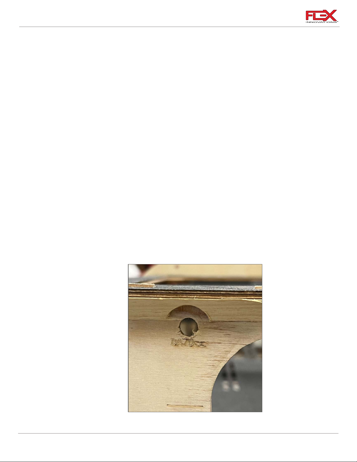
1. The engine mounting location for the DA-70 is laser-etched into the firewall for your
convenience. If you will be using an engine with a different mounting pattern, the “+”
represents the engine crankshaft.
Use a ⅛-inch drill bit and drill to create a pilot hole in the center of the four bolt hole
etchings in the firewall. Use a19/64-inch drill bit to enlarge these holes to the appropriate
size of the blind nut.
There is also a laser etching for the throttle linkage just below and to the left of the lower
right mounting hole (when looking at the firewall from the front). You can open this hole
at this time as well if using the DA-70. Other engines may require a different hole
location.
!
19
!
Page 24
Cap 232EX 70cc Instruction Manual
!
!
!
Required for this section
Components
Tools
Adhesives/Building Materials
o Fuselage Assembly
o Throttle Servo
o 9-inch (230mm) Servo
Extension
o 2mm White Ball Link
o Throttle pushrod
o M2x10 Phillips Head
Screw (1)
o M2 Flat Washer (2)
o M2 Lock Nut (1)
o Quick connect assembly
o #1 Phillips Screwdriver
o 2.5mm Hex Driver
o Thin CA
o Blue Thread Lock
o Heat Shrink, Dental Floss or
Safety Clips
2. Use a a knife or a rotary tool with small sanding drum to remove a small section of the
triangle stock near the upper mounting holes for the engine (as shown above). Be sure to
remove the triangle stock completely as this is to allow room for the engine standoffs to
sit squarely on the firewall.
3. Install the blind nuts in the firewall. Add thin CA to secure the blind nuts making sure you
don’t get any adhesive on the threads inside.
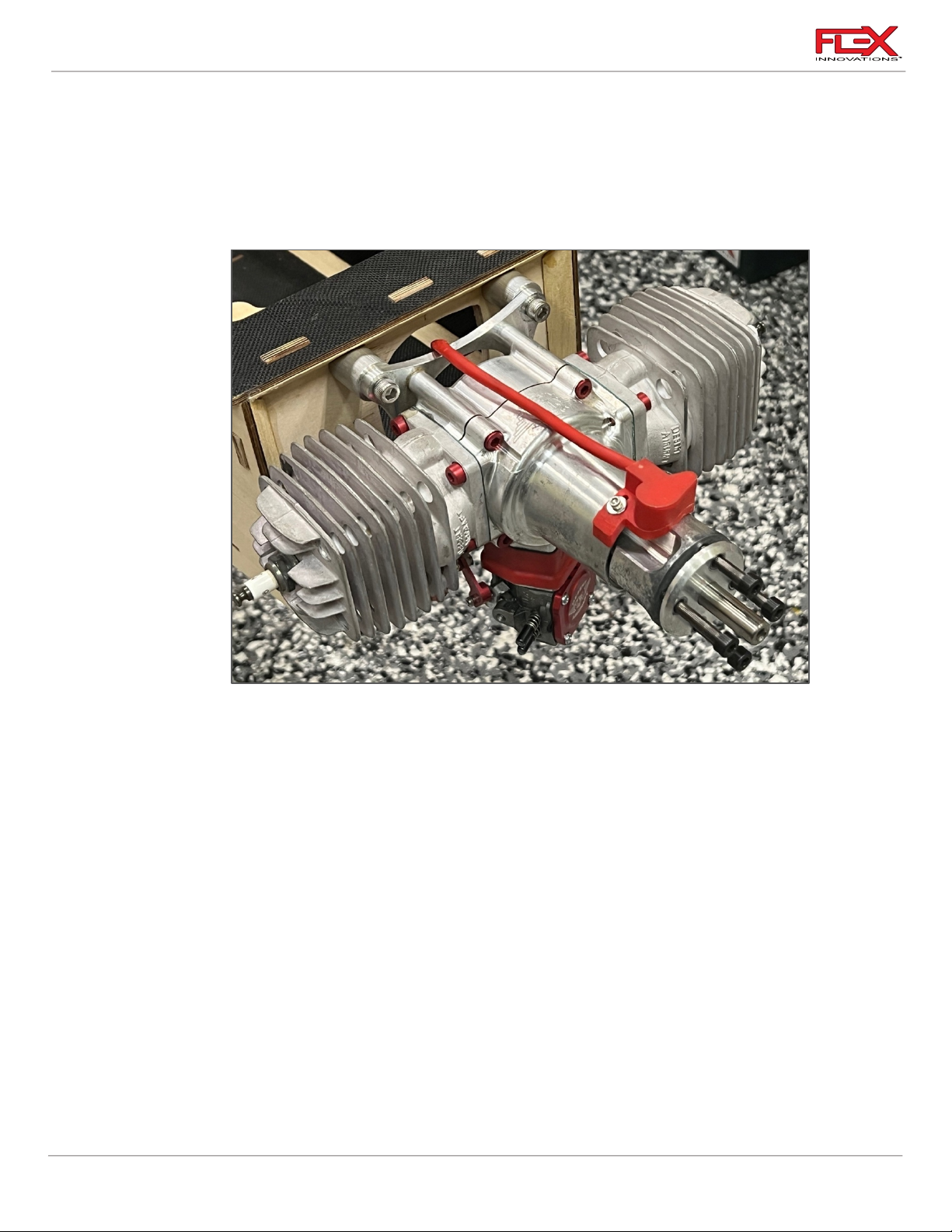
4. Mount the engine (without the exhaust) to the firewall using (4) 15mm engine standoffs,
(4) ¼-20 x 1-3/4-inch socket head cap screws, (4) ¼-inch flat washers. Apply Blue Thread
Lock to the mounting bolts.
DA-70 Throttle Servo and Linkage Installation
20
!
Page 25
Cap 232EX 70cc Instruction Manual
!
!
!
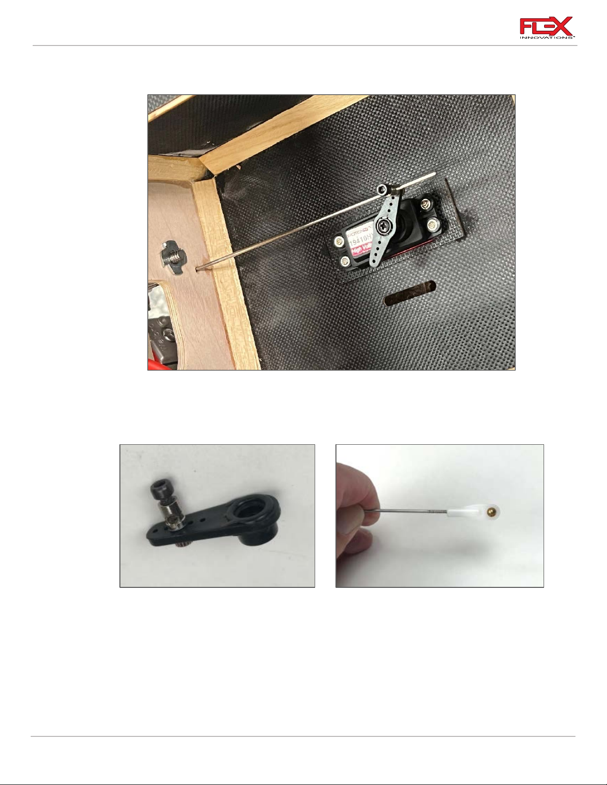
1. Thread a servo mounting screw into each of the four mounting screw holes in the motor
box. Apply thin CA to each of the holes to harden the threads.
!
2. Attach the 9-inch (600mm) servo extension to the throttle servo. Use a Servo Connector
Safety Clip (FPZA1040), thread or heat shrink tubing to secure the extension in place.
Mount the servo with the output shaft towards the tail of the aircraft and route the servo
extension appropriately through the aircraft.
3. Secure the quick connector to your servo arm. We prefer to use a plastic servo arm 25mm
long. Be sure to use blue thread lock for a secure attachment. The order of components is
as follows:
!
o Quick connect housing
o Washer
o Servo Arm
o Washer
o Nut
21
Page 26
Cap 232EX 70cc Instruction Manual
!
!
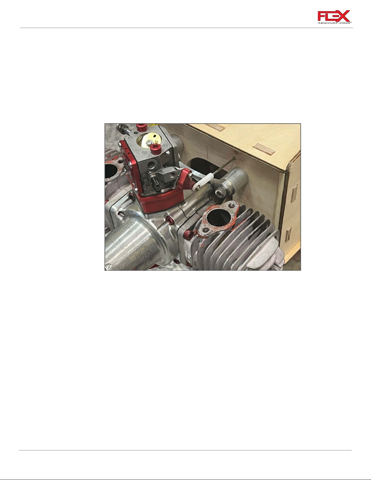
4. Locate the pushrod threaded on one end. Thread a white ball link approximately halfway
on to one end of the linkage.
5. Use an M2x10 socket head cap screw, M2 washer, and M2 lock nut to secure the end of
the linkage with the ball link to the throttle arm on the carburetor. On the DA-70, this is
the outermost hole on the throttle arm. The order of components is as follows:
o M2x10 Socket Head Cap Screw
o M2 Washer
o Throttle Arm
o M2 Lock Nut
6 Remove the M3x5 socket head cap screw from the quick connect. Insert the non-threaded
portion of the throttle linkage through the hole in the side of the quick connect. With the
radio powered on, center the throttle servo and engine throttle arm. Use blue thread lock
and secure the M3x6 screw onto the linkage. Check throttle movement and position
relative to stick position and make any changes necessary. Fully tighten the screw.
Quique Pro Tips:
• Use the shortest servo arm possible while still getting full throttle arm movement on your
engine. Your throttle end points should be around 110-120% when finished with the
installation. A faster servo (like the Potenza DS49010HV) with a shorter arm is preferred over a
slower servo with a longer arm.
• For the most linear throttle response, adjust the throttle linkage length to balance the end
points for your throttle servo. You do NOT want your end points to be mismatched (example:
60/120). Set your end points as close to one another as possible (example: 114/116) for the
most linear throttle response.
!
22
Page 27
Cap 232EX 70cc Instruction Manual
Required for this section
Components
Tools
Adhesives/Building Materials
o Fuselage Assembly
o Ignition
o Ignition Switch
o Ignition Battery or IBEC
o Regulator (if applicable)
o Hobby Knife w/#11 Blade
o #1 Phillips Screwdriver
o Hook and Loop Strap (2)
o Adhesive-Back Hook and
Loop Tape
!
!
IGNITION INSTALLATION
!
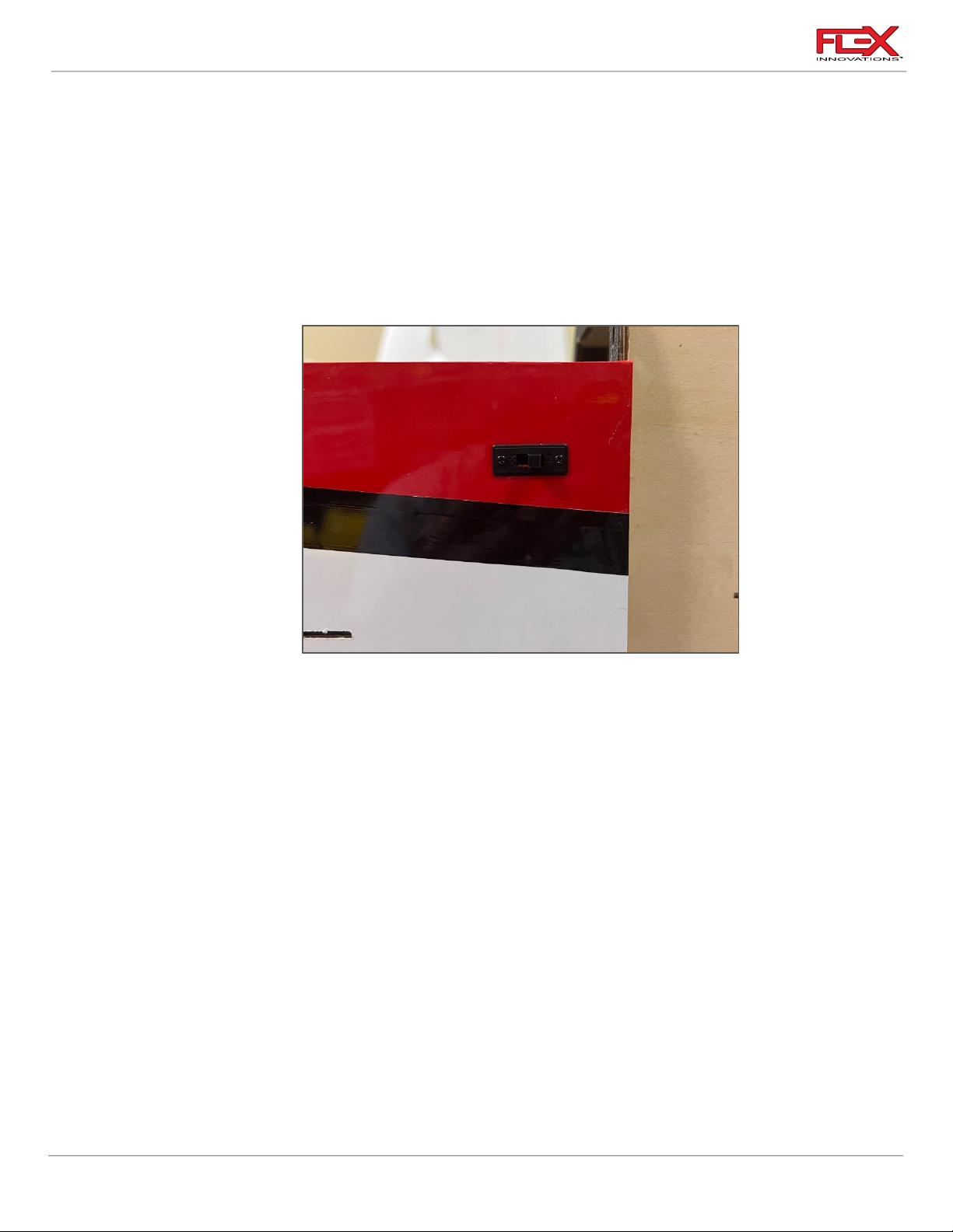
1. Locate the ignition switch hole towards the nose of the fuselage. Note that there are
switch locations on both sides of the fuselage for your preference. Use a hobby knife with
a #11 blade to remove the covering from the hole of your choice. Test fit your switch and
modify the hole if needed. Secure it in place using the screws included with your switch.
If your switch mounting screws thread into metal, be sure to apply blue thread lock. DO
NOT apply blue thread lock if they thread into plastic.
2. The ignition can be mounted wherever you prefer. We have found that with the DA-70,
the inside of the motor box hatch is a preferred location. There are many ways to install
an ignition and we recommend you mount it per your engine manufacturer’s
recommendations.
23
Page 28
Cap 232EX 70cc Instruction Manual
!
!
!
!
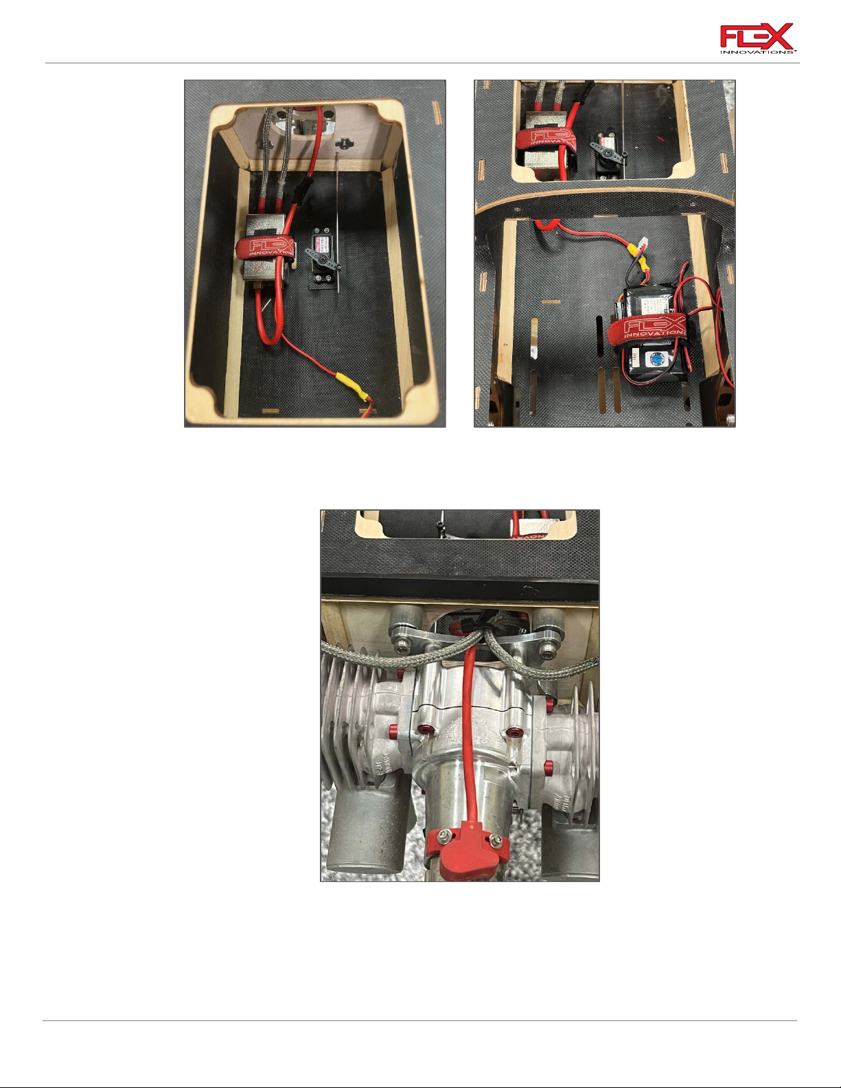
3. If you are using an ignition battery, we recommend using a 2S 2000mAh Li-Po
(FPZBR20002S15) placed on the front hatch. Use adhesive-backed hook and loop tape
between the battery and the hatch and secure the battery with a hook and loop strap.
!
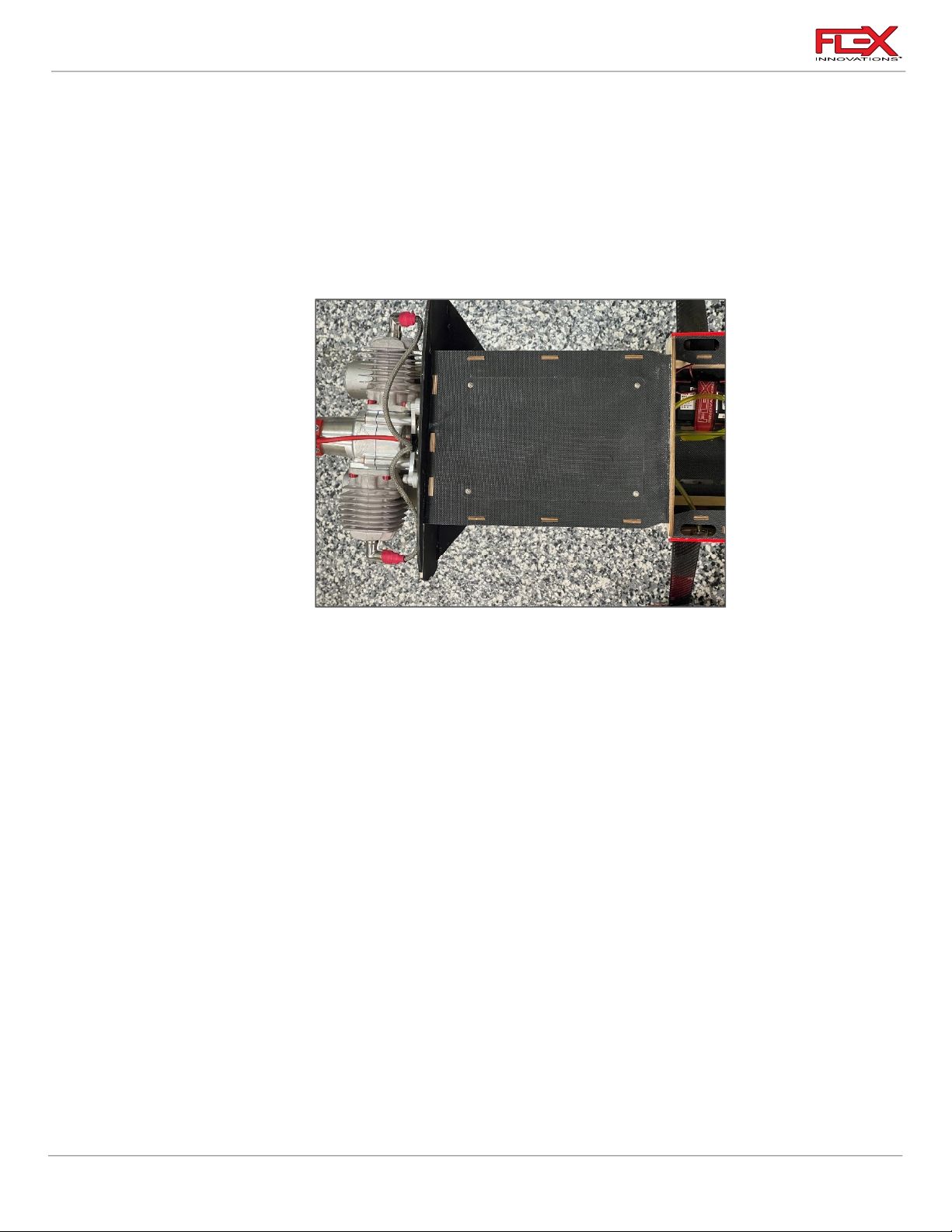
4. Route all your ignition spark plug wires through the large hole in the middle of the
firewall.
5. Secure any permanent connections with heat shrink dental floss or servo safety clips
(FPZA1040). Be sure to secure the wiring so that it will not bounce around in the aircraft.
Also, be sure to secure the wiring in a way that the wires will not chafe against sharp
24
Page 29
Cap 232EX 70cc Instruction Manual
!
Required for this section
Components
Tools
Adhesives/Building Materials
o Fuselage Assembly
o Fuel Tank
o Fuel Line
o Pliers
o Hook and Loop Strap (2)
o Adhesive-Back Hook and
Loop Tape
o Cable Ties
edges from vibration. A typical ignition setup will be connected as follows:
Ignition Battery ➞ Ignition Switch ➞ Ignition Regulator ➞ Ignition ➞ Engine
Or (if using an IBEC):
Receiver Channel ➞ IBEC ➞ Ignition ➞ Engine
6. Locate the (4) M3 x 15mm socket hex screws and (4) Flat washers for the motor box
access hatch. Apply blue Thread Lock and Use a 2.5mm driver to tight the four screws.
!
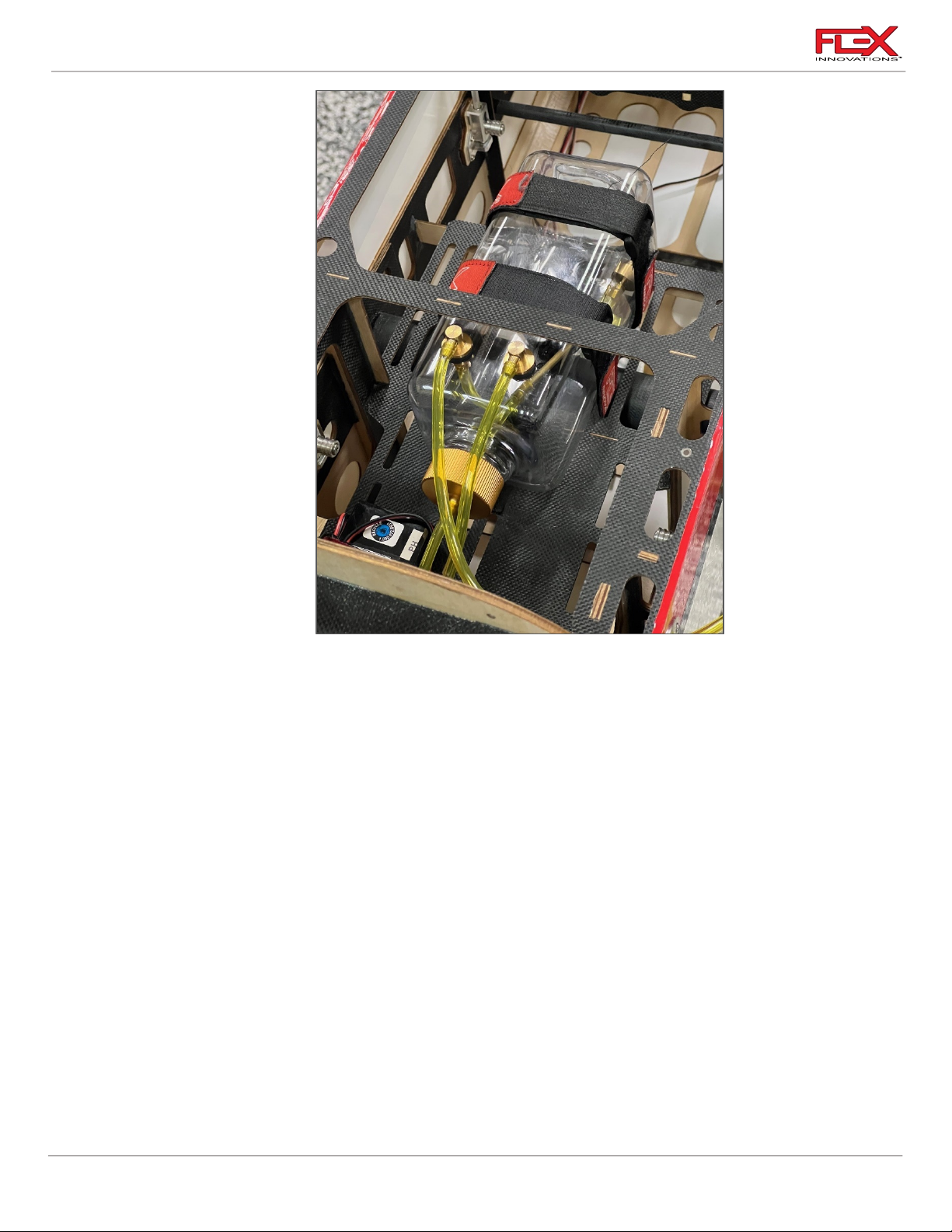
FUEL TANK INSTALLATION
The Flex Innovations Lightweight 700cc Fuel Tank is included with your Cap 232EX 70cc. Before
installing the fuel tank check all fittings are properly installed and that the clunk line inside the tank is
appropriately sized. Adjust as necessary.
25
Page 30
Cap 232EX 70cc Instruction Manual
!
!
1. The fuel tank tray has plenty of room for your fuel tank. If you are using a single tank, you
can place the fuel tank in the middle of the tray as shown in the image above. If you plan
on using a smoke system, two of the 70cc Lightweight Fuel/Smoke tanks (FPM2019)
should be used, installed side by side. One is included in your kit. Both tanks should be
center over the wing tube in order to be closer to the airplane’s CG.
Apply adhesive-backed hook and loop tape to the bottom of your tank(s) and to the fuel
tank tray. Place the tank(s) in their location and secure them with two hook and loop
straps. These straps should be snug but not overly tight, as the fuel tanks are very
lightweight and can be easily crushed. The hook and loop tape on the bottom of the
tank(s) will prevent the tank from moving fore and aft, and the hook and loop straps will
prevent the tank from pulling away from the tray.
26
Page 31
Cap 232EX 70cc Instruction Manual
!
Required for this section
Components
Tools
Adhesives/Building Materials
o Fuselage Assembly
o Cowling
o Cowling Baffles
o Your Exhaust Choice
o (4) M2.5 x 4 Wood Screws
o Motor Box Cover Plate
o Canister or Pipe Mount
o Rotary Tool
o Rotary Tool Sanding
Drum
o Rotary Tool Cut-Off
Wheel
o Felt-Tipped Pen
o Covering Iron
o Thin CA
o CA Accelerator
o Blue Thread Lock
o 30 Min Epoxy
o Mixing Cups
o Mixing Sticks
o Paper Towels
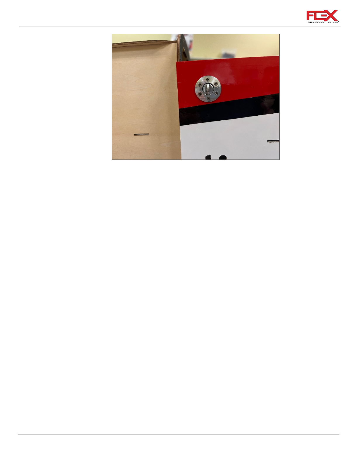
2. After the tank is in position, route and trim your fuel lines appropriately. Your clunk line
should go to the carburetor or throttle body. The fill line should go to your fuel dot or
filling system. We recommend the McFueler Fuel Dot (FPMAMCFUELER). The vent line
should wrap around the back of the tank(s) and pass back in front of the tank(s). It should
then exit the bottom of the fuselage. After the vent line exits the fuselage, use a cable tie
around the fuel line to prevent it from slipping back into the fuselage. Don’t overtighten
the cable tie, as air and fuel will need to vent from this line. Be sure to keep your fuel line
away from components that get hot (like your exhaust or cylinder heads) and route it in
such a way that it will not bounce around or chafe on any of the interior structure of the
fuselage.
!
EXHAUST AND COWLING INSTALLATION
If you plan to use stock mufflers, please follow the instructions (A) below. If you plan on using a
canister exhaust setup, please follow the canister isntallation (B) instructions starting on page 30. Be
sure to follow the engine baffling instructions for both setups. Different engines and exhaust setups
may require significantly different installations. You will need to decide what is best for your setup.
27
Page 32
Cap 232EX 70cc Instruction Manual
!
!
Muffler Installation (A)
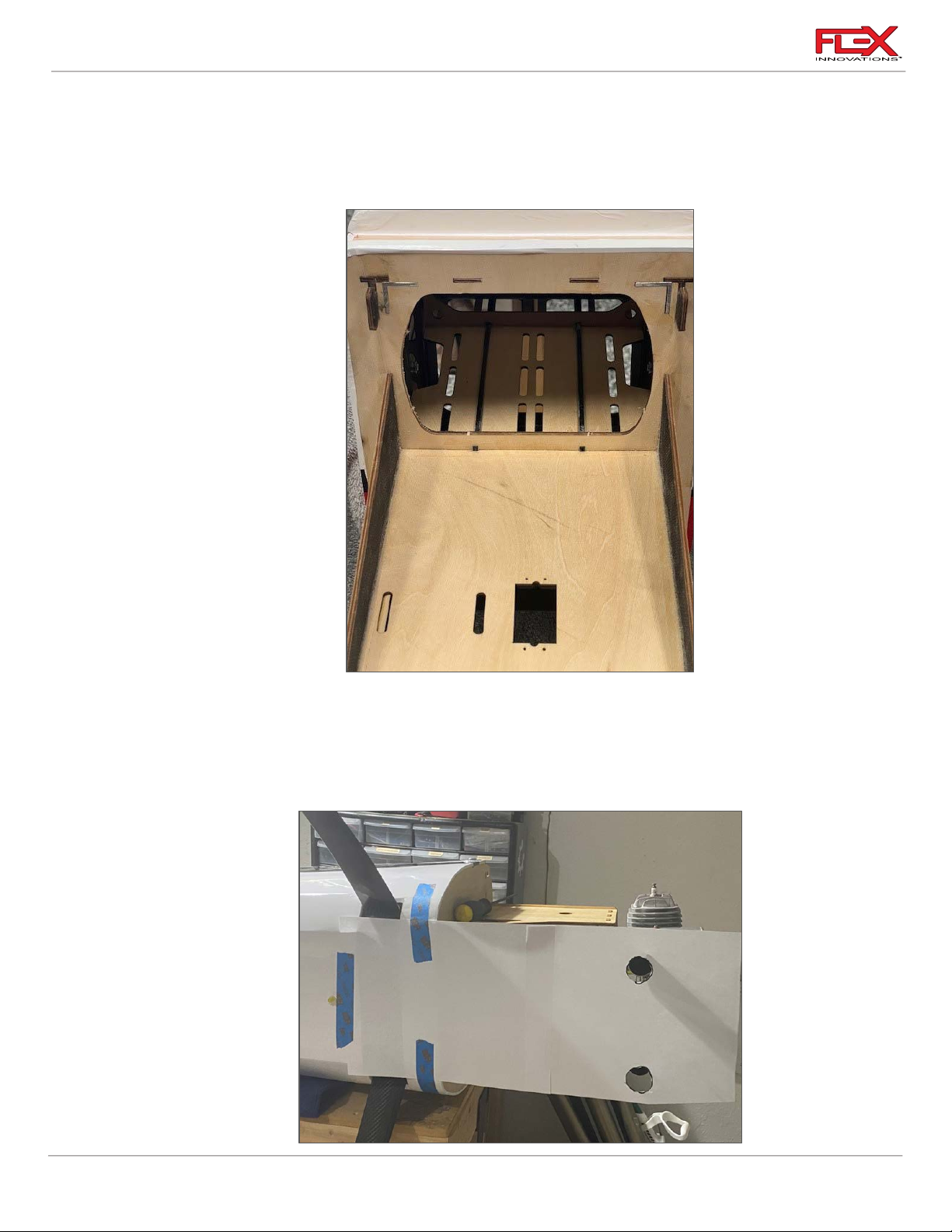
1A. With the fuselage inverted on your work bench, break loose the rectangular plate to
allow air to go through the inside the fuselage. This is an important part of the baffling
and cooling system for the engine.
!
2A. Temporarily install the mufflers on the engine using the hardware provided with your
engine. Follow your engine manufacturer’s installation instructions. Use a couple sheets
of paper or card stock and some low tack tape to secure the paper to the fuselage. You
want the other side of the paper to extend over the exhaust exit holes. Mark the exhaust
exit holes on the paper as shown in the picture below.
28
!
Page 33
Cap 232EX 70cc Instruction Manual
!
!
!
!
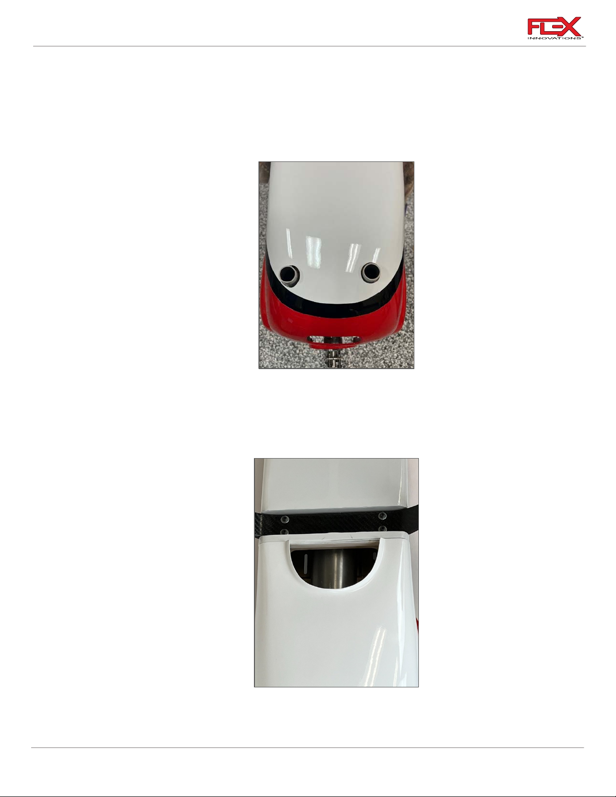
3A. Keeping the paper temlate in place, remove the mufflers from the engine and install the
cowling. Transfer the marks from the template onto the cowling using a felt-tipped pen.
Once the marks are transferred, you can remove the tape and paper, as well as remove
the cowling.
4A. Permanently install the mufflers on the engine following your manufacturer’s
instructions.
!
5A. Use a rotary tool with a sanding drum to begin cutting the cowling at the front edge of
the marks completed in the previous step. Only remove a small amount of material at a
time, and test fit the cowling in between each step. Take note of where the mufflers hit
the cowling and continue removing material until you can fit the cowling on the aircraft
with the mufflers installed. Remove the cowling.
!
6A. Cut the rest of the cowling out, following the low-pressure lip shape in the cowling. Leave
approximately 1/16-inch (1.5mm) of material along the low-pressure lip side of the
cutout. Leave approximately ½-inch (12mm) of material at the rear edge of the cutout.
29
Page 34
Cap 232EX 70cc Instruction Manual
!
Required for this section
Components
Tools
Adhesives/Building Materials
o Fuselage Assembly
o 2-to-1 Exhaust Header
o Canisters
o Exhaust Gaskets (2)
o Canister Mount Plate
o Silicones Tubes
o M3 x 15 Socket Head Cap
Screws (4)
o M3 Flat Washer (4)
o 4mm Driver
o 2.5mm Hex Driver
o #11 Exacto Knife
o Red Silicone (RTV)
o Paper Towels
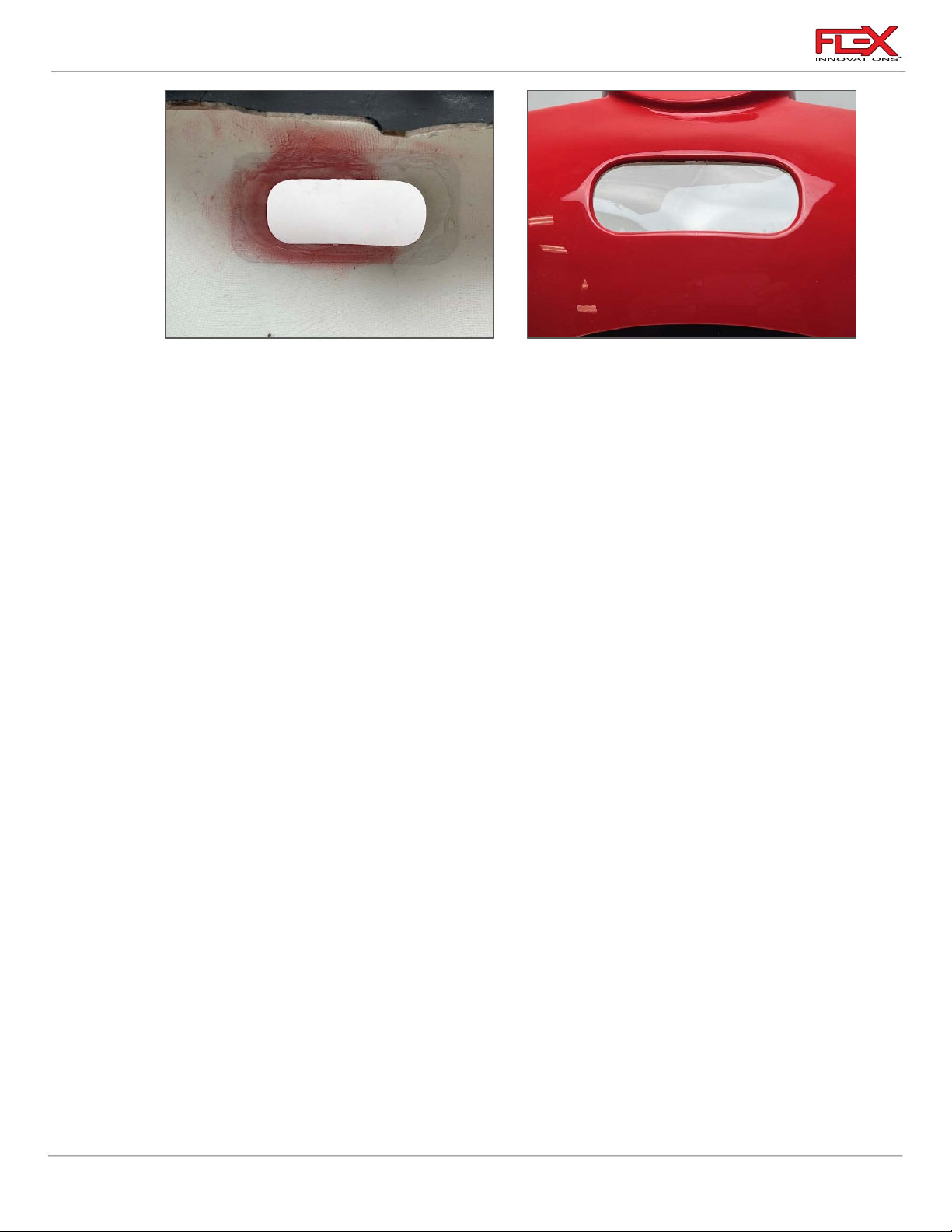
7A. For proper function of the “L” baffle system it is important to keep the front cowl hole
closed off. If you leave this hole open the pressure will equalize the upper area (cylinder
area) causing the air not to escape from the cylinder and the engine will overheat. The
picture shows some clear plastic used to seal off the hole, (we used the spinner
packaging material and glued it in place with CA adhesive). This clear window is great to
see the engine needle for tuning.
!
Canister Installation (B)
Recommended canister and headers for the different engines are listed in the front section of the
manual.
30
Page 35
Cap 232EX 70cc Instruction Manual
!
!
!
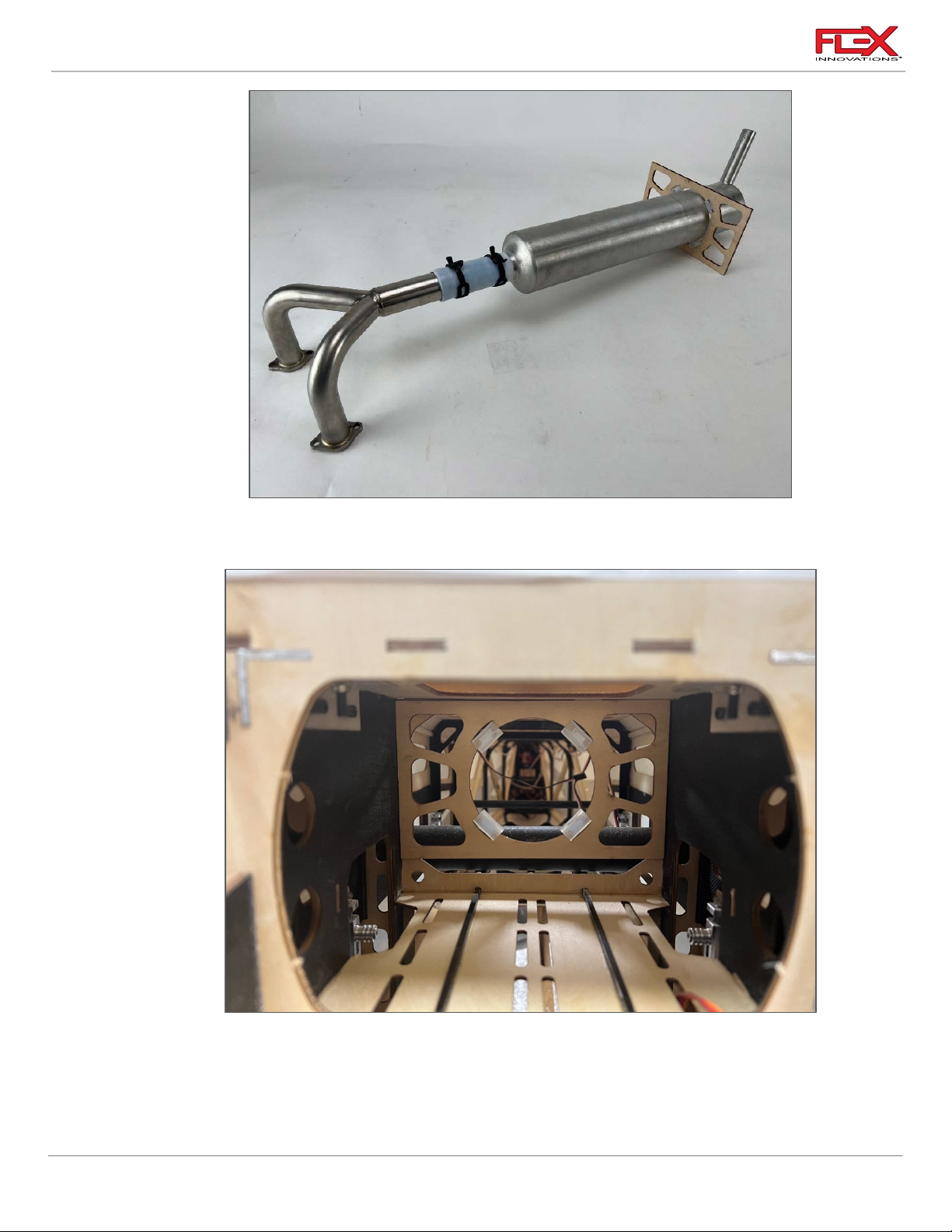
1B. Install the 4-silicone tubes into the canister mount plate. Place the mount plate in the
location shown in the image above. Test fit and remove the plate.
2B. Glue the plate as shown in the picture. Note that the canister hole is closer to the bottom
of the airplane to allow clearance for the wing tube.
31
!
Page 36
Cap 232EX 70cc Instruction Manual
!
!
!
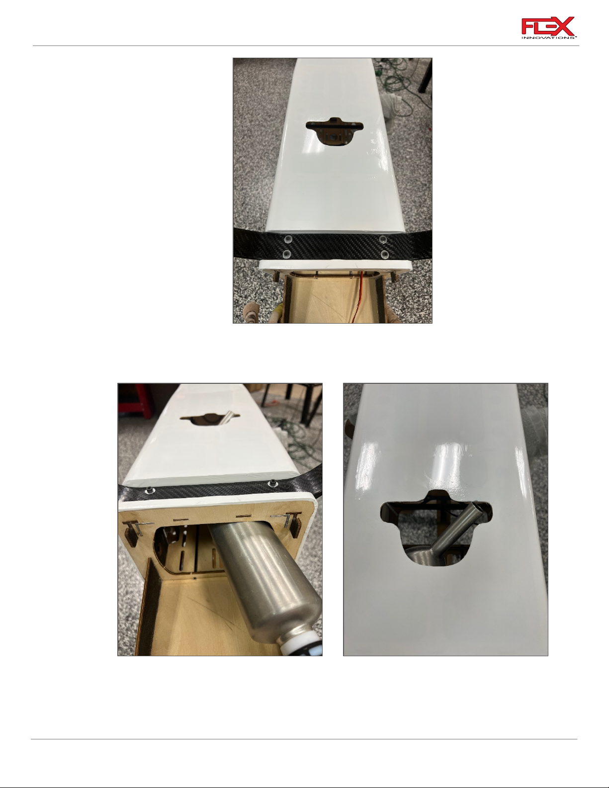
3B. Remove the film covering the cannister exhaust port on the bottom of the fuselage using
an #11 Exact knife. Alternately, a hot soldering iron tip can work well to open and seal the
covering at the same time.
6. Install the canister through the canister mount rotated and at an angle as shown in the
the pictures anpve. Once the canister tail pipe clears the exit hole you can turn it and
alight the headers with the engine cylinder exhaust ports.
32
!
Page 37
Cap 232EX 70cc Instruction Manual
!
Required for this section
Components
Tools
Adhesives/Building Materials
o Fuselage Assembly
o Cowling (2 halves)
o Cowling Baffles
o Ruler
o 30 minute Epoxy
o Medium CA
o CA kicker
o Mixing Sticks
o Paper Towels
7. Install the exhaust on the engine using the hardware provided with your engine. Follow
your engine manufacturer's installation instructions. Typically, most engines will use a
gasket between the muffler and cylinder and the socket head cap screws will pass
through a lock washer before securing the cannister header to the cylinders.
!
Engine Baffling Installation
33
!
Page 38
Cap 232EX 70cc Instruction Manual
!
!
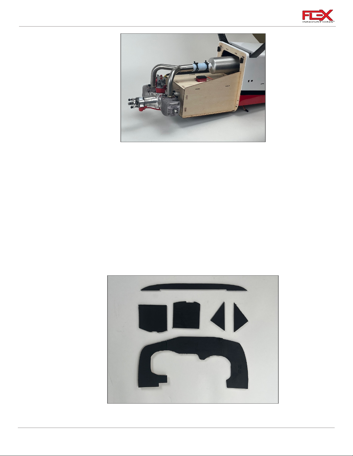
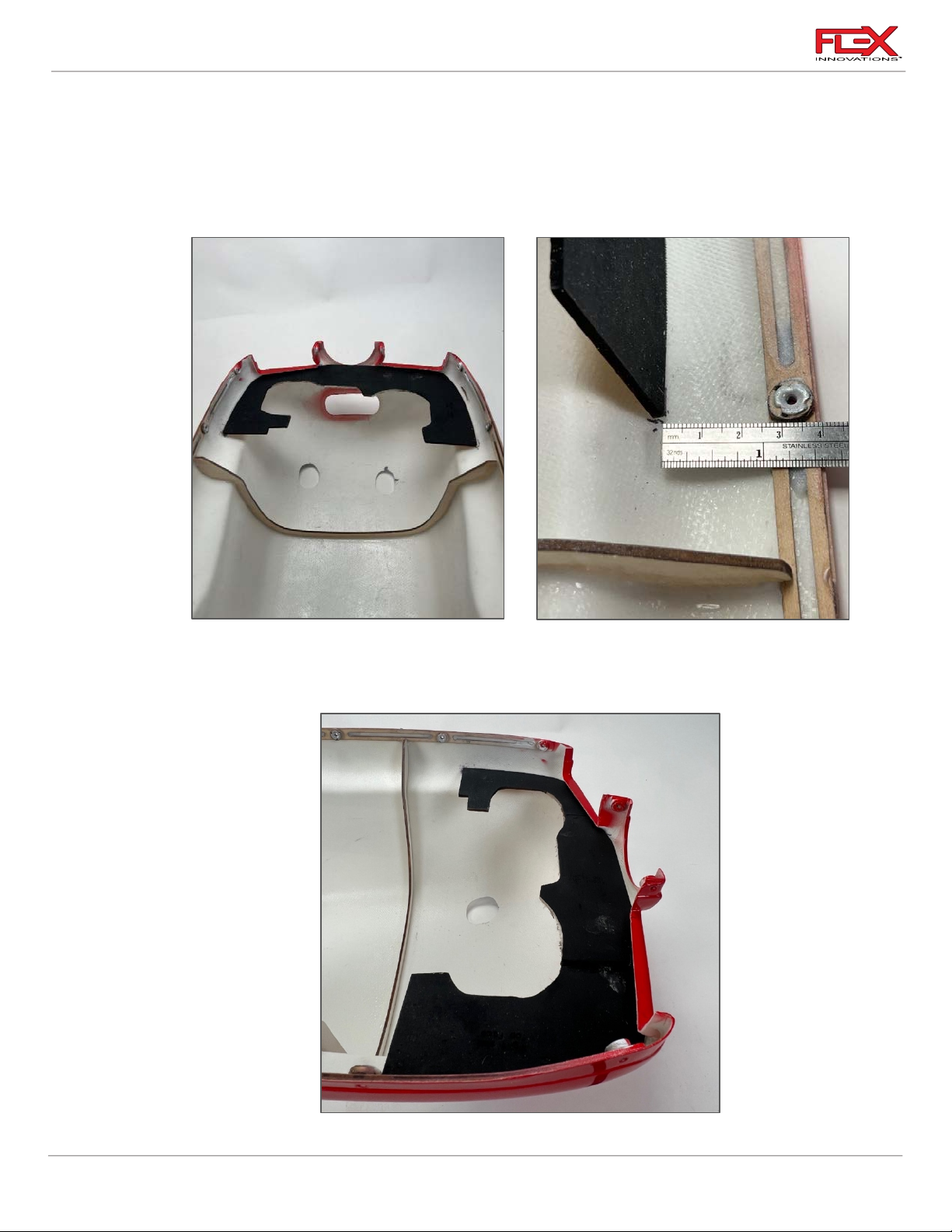
1. The Cap 232EX 70cc baffle system is the same as the one used in full scale airplanes. This
is an “L” baffle system and not a pass-through system as use by most model airplanes.
Locate the engine baffles. Each piece is laser engraved for location. The larger piece will
be glued to the cowl, while the rest of the pieces are glued to the motor box. Note that a
coat of flat black paint has already been applied in these pictures. Painting the baffles is
optional, you can use any color or even leave it as stock in natural wood color.
2. The baffle will be glued 40mm below the side edges of the cowling and parallel to the
sides. See above pictures for reference. Do not bond any of the parts permanently until all
the baffle system pieces are fitted
!
34
!!
Page 39
Cap 232EX 70cc Instruction Manual
!
!
!
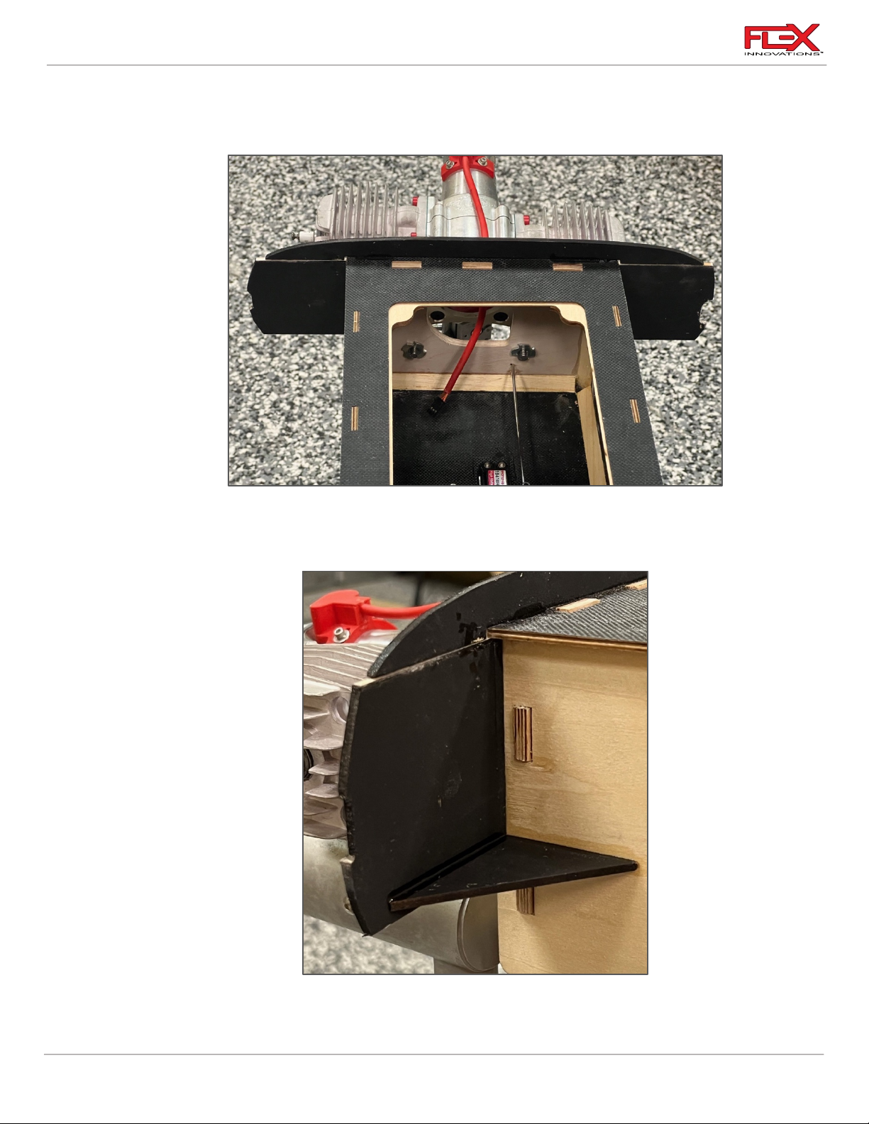
3. Start by tacking the rear baffle in place with a few drops of CA and kicker as necessary.
After it is temporarily tacked in place, verify the proper fit around the engine. Adjust if
needed with a file, sandpaper or rotary tool with a sanding drum.
4. Use CA to tack the baffle top and side pieces to the motor box as show in the picture
above. The middle piece is marked as “top front” the side pieces are marked as “Rear Left”
and “Rear Right” with arrows indicating top side.
!
!
5. Tack in place the two triangle shape pieces to the right and left side of the motor box.
These triangles are there to support the lateral pieces.
35
Page 40
Cap 232EX 70cc Instruction Manual
!
Required for this section
Components
Tools
Adhesives/Building Materials
o Fuselage Assembly
o Cowling
o Propeller
o Spinner
o (10) M3 x 10 Hex Button Head
Hex Bolt
o (4)M3x20 Hex Bolt
o (4) M3 Washer
o M2.5 Hex Driver
o M2 Hex Driver
(Spinner)
o Blue Thread Lock
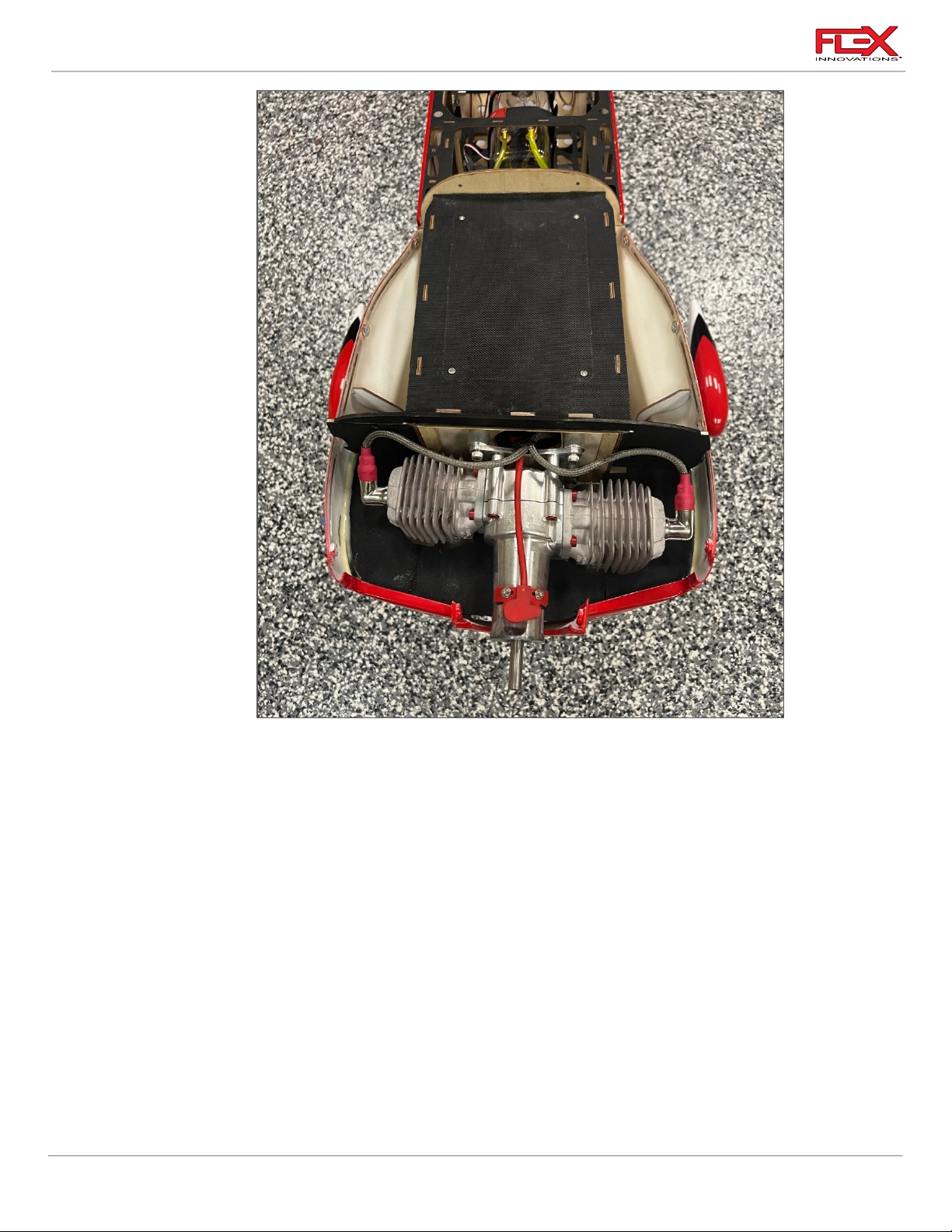
6. Once all pieces are tacked in place do a final test fit. The picture above shows how it
should look when all the baffle pieces are installed properly. Remove the cowling and 30
minute epoxy to permanently bond all baffle pieces in place.
COWLING, PROPELLER AND SPINNER FINAL INSTALLATION
36
!
Page 41
Cap 232EX 70cc Instruction Manual
!
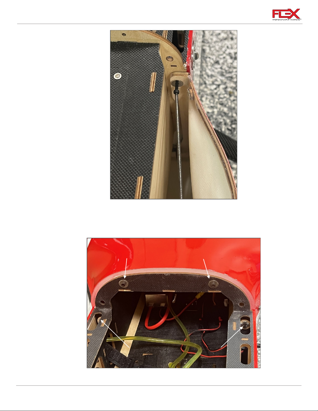
Bottom cowling screws (front side)
Top cowling screws (rear side)
!
1. The cowling is supported by (2) M3x20 hex bolts at the top and two hooks at bottom of
the cowl. Install the (2) M3x20 bolts with a flat washer. Apply Blue Thread Lock. Use a
2.5mm hex driver and tighten well. As shown in the picture above, the bolts are installed
from the front of the cowling.
37
!
Page 42
Cap 232EX 70cc Instruction Manual
!
!
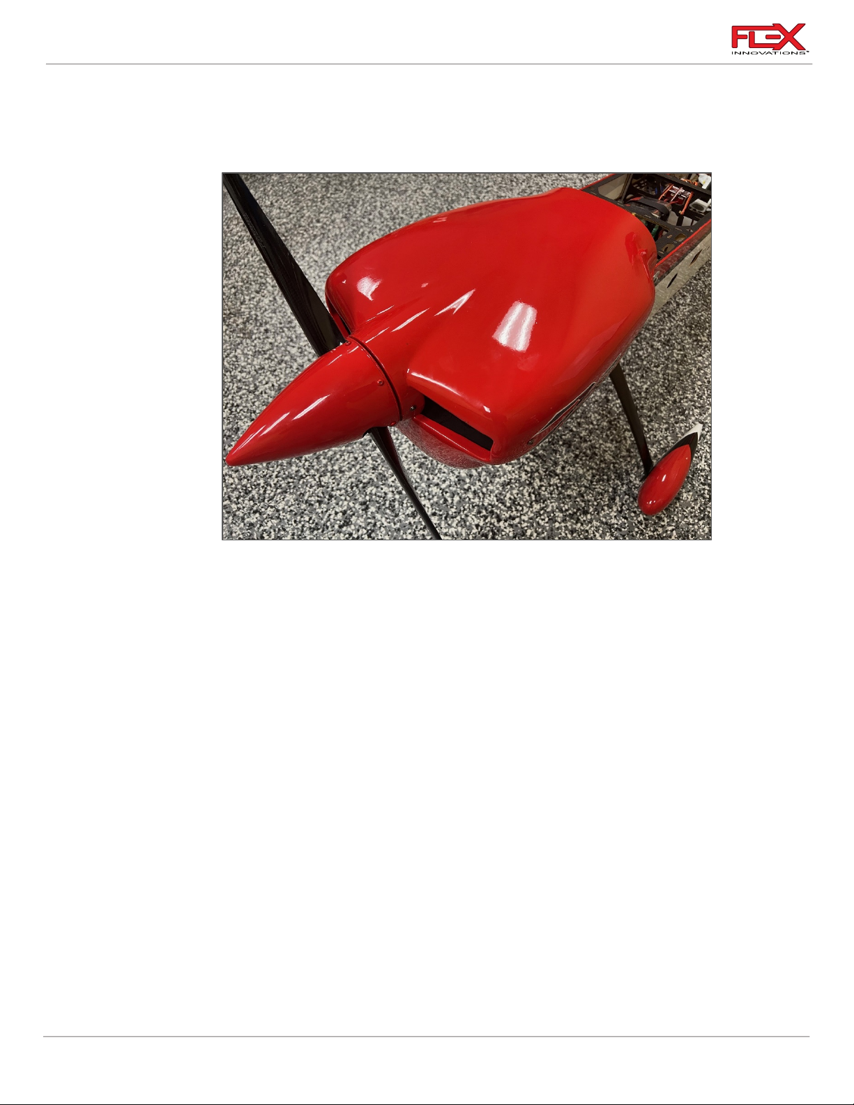
2. Install the cowling top onto the cowling. Use (10) M3x10 Button Head Hex bolts with blue
thread locket along the sides of the cowling to join the two cowling halves. Next, install
the (2) M3x20 and (2) M3 Flat washers from the rear on top side of the cowl, also using
blue thread lock. See above picture for reference.
!
3. Once the cowling is in place, drill and install your propeller and spinner. We recommend
the Falcon 24 x 9 propeller and our 4-inch “Edge-style” spinner for the perfect match.
38
Page 43

Cap 232EX 70cc Instruction Manual
Required for this section
Components
Tools
Adhesives/Building Materials
o Fuselage Assembly
o Motor
o M5x15 Socket Head Cap
Screw (4)
o M5 Flat Washer (4)
o 1/4x3/4 Socket Head Cap
screw (4)
o ¼ Flat Washer (4)
o 2.5in (60mm) Standoff (4)
o M5x15 Socket Head Cap
Screw (4)
o M5 Flat Washer (4)
o 2mm Hex Driver
o #1 Phillips Screwdriver
o Blue Thread Lock
o 5min Epoxy
o Mixing Cups
o Mixing Sticks
ELECTRIC POWER SETUP
The Cap 232EX 70cc was designed for electric power as well.
Flight time with the recommended equipment is around 4 to 5 minutes with proper throttle
management, leaving you with good reserve. For your first flights on the recommended setup, set
your timer for 3 minutes and check the remaining capacity when charging your batteries. Adjust the
timer according to your personal flight style.
Recommended Electric Power System:
o Potenza 65cc 185kV Motor (FPZM65CC)
o (4) 2.5 in (60mm) motor standoffs (included with Potenza 65cc motor)
o Potenza 6S 6200mAh 40C batteries (two in series for 12S)
o Minimum 160amp 12S capable ESC
o Mejzlik 25 x 12S Propeller
MOTOR INSTALLATION
39
Page 44
Cap 232EX 70cc Instruction Manual
!
!
!
!
Required for this section
Components
Tools
Adhesives/Building Materials
o Fuselage Assembly
o ESC
o M2x12 Phillips Head Self-
Tapping Screws (4)
o #1 Phillips Screwdriver
o Drill
o 1.5mm Drill Bit
o Thin CA
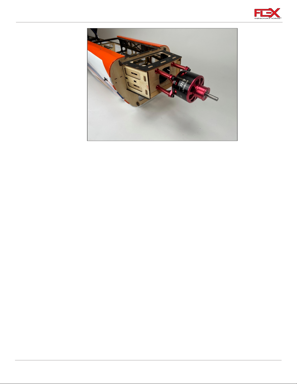
1. The Potenza 65cc motor has the same bolt pattern as the DA70cc. Starting with a 3mm
drill bit, drill the 4 pilot holes at the marked locations on the motor box. Enlarge the holes
using the 5mm drill bit.
!
2. The 60mm motor standoffs used are threaded for ¼ -20 bolts on the motor side and 5mm
bolts on the firewall side.
3. Use (4) ¼ x ¾-inch socket head cap screws and (4) ¼-inch washers to mount the motor.
Be sure to apply blue thread lock when securing them.
4. Install the motor to the firewall using (4) M5 x 10 socket head cap screws with (4) M5
washers. Be sure to use blue thread lock when securing them.
ESC INSTALLATION
40
Page 45
Cap 232EX 70cc Instruction Manual
!
!
Required for this section
Components
Tools
Adhesives/Building Materials
o Fuselage Assembly
o Sticky Velcro
o Flex Innovations Battery
Hook and Loop Strap
Medium 30mm Long (4).
FPMA1016
o 30 Minute Epoxy
o Mixing Cups
o Mixing Sticks
!
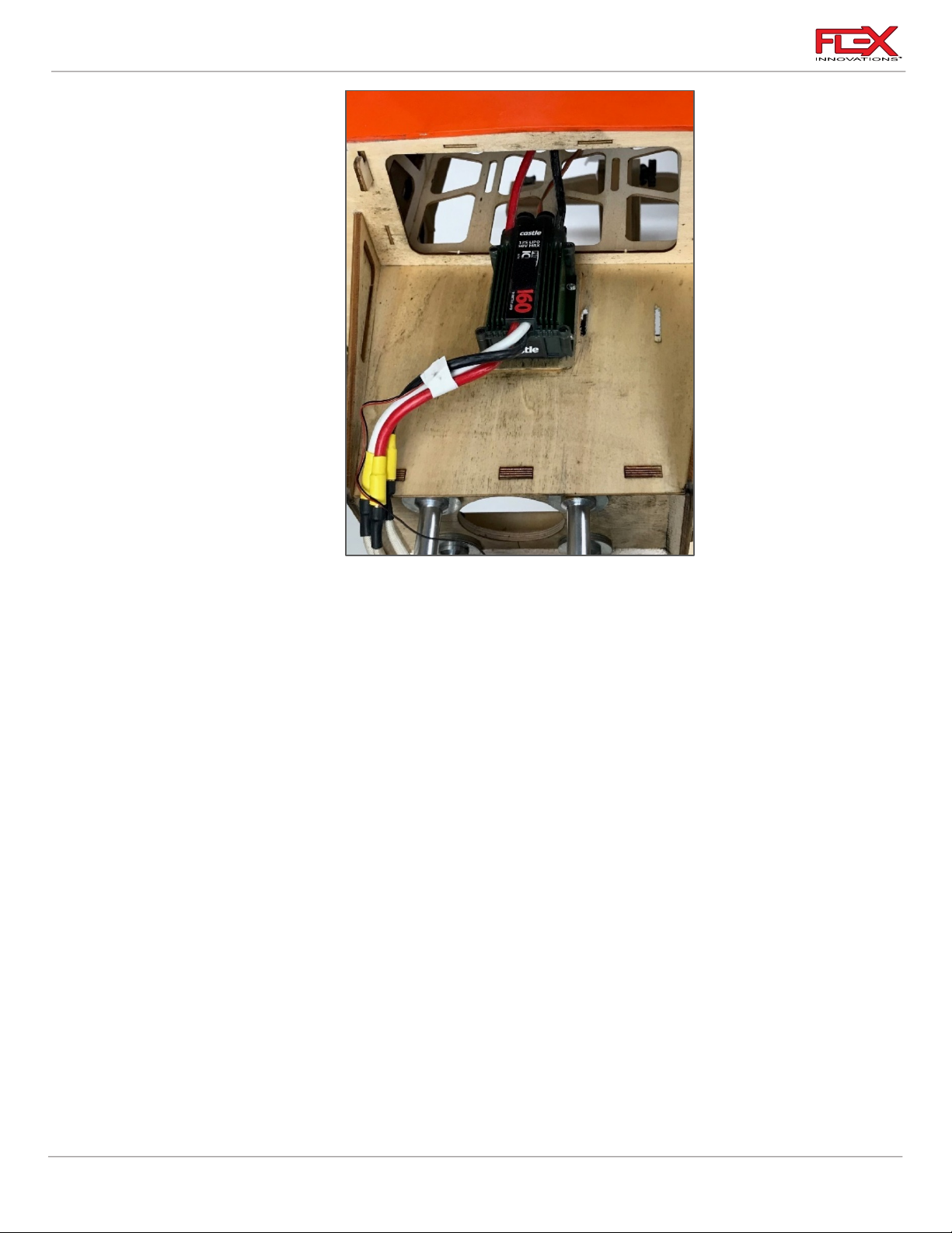
1. Mount the ESC on the bottom of the motor box as shown in the picture above. This is a
great location for cooling. Mark the mounting hole locations and use a 1.5mm drill bit to
drill holes in the motor box. Using a #1 Phillips Screwdriver, thread an M2 x 12
Phillipshead self-tapping screw into each of the holes. Remove the screw. Use thin CA to
harden the threads, and once the CA has fully cured, you can install your ESC.
2. Tidy up and secure all the wiring.
BATTERY TRAY INSTALLATION
41
Page 46
Cap 232EX 70cc Instruction Manual
!
!
!
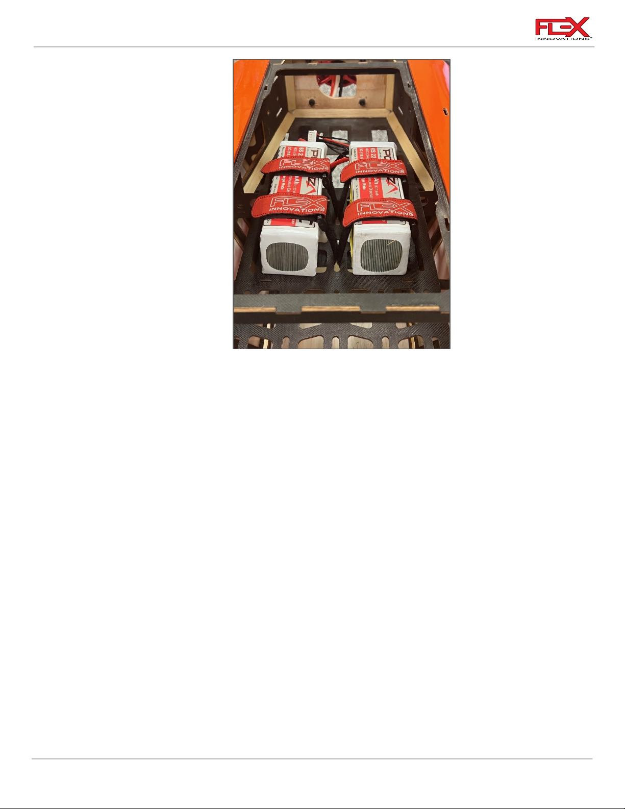
1. Apply adhesive-backed hook and loop tape to the tray. With the recommended electric
set-up, the batteries should be placed roughly in the location shown in the pictures
above.
2. Install four 300mm (11-3/4 inch) Flex Innovations Hook and Loop straps through the slots
in the battery tray to secure the electric flight batteries. There are several slots to choose
from, select the slots that work with your battery location.
Quique’s Tip:
o The battery location can be significantly different if other components are used, such as
motor, ESC, battery, prop, spinner etc. Note: RX battery placement can be used to adjust the
CG. The Cap 232EX 70cc has multiple trays, from nose to cockpit, to choose from when
mounting the RX battery to achieve the correct CG.
42
Page 47
Cap 232EX 70cc Instruction Manual
!
!
!
MOTOR/ESC COOLING
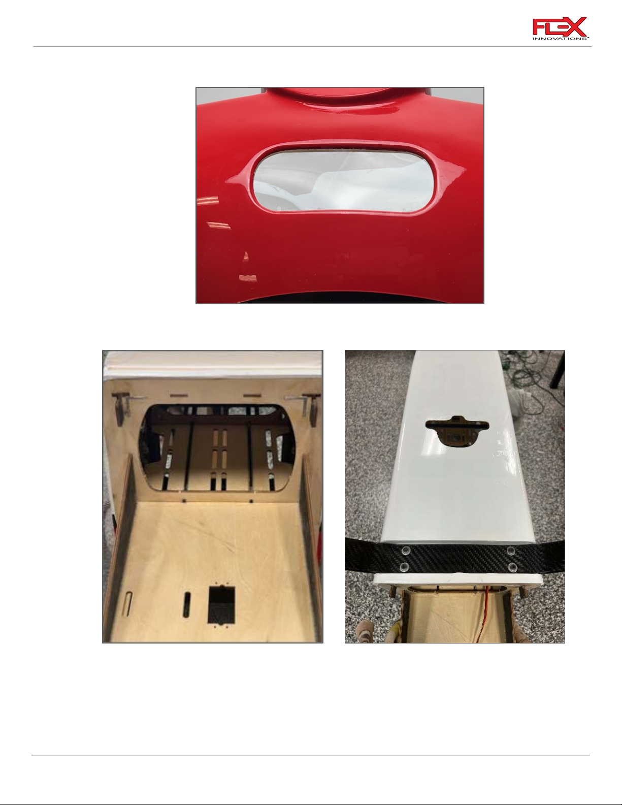
1. When using the electric power setup, we recommend you remove the plastic in the
opening in the lower front of the bottom cowling to allow for cooling air to cool the ESC.
!
2. The covering on the fuselage front lower openings must be removed to allow the hot air
to escape through the belly.
3. When using the electric power setup, we recommend that you do not use the provided
baffles for gas engines. The front openings provide enough cooling for the electric motor
on their own.
43
!
Page 48
Cap 232EX 70cc Instruction Manual
Required for this section
Components
Tools
Adhesives/Building Materials
o Fuselage Assembly
o Rudder Control Horns (2
or 4)
o Rudder Control Horn
Base Plates (1 or 2)
o Hobby Knife with a #11
blade
o #1 Phillips Screw Driver
o Isopropyl Alcohol
o 30-minute Epoxy
o Mixing Cups
o Mixing Sticks
o Paper Towels
o Thin CA
o Heat shrink, dental floss or
safety clips
!
RUDDER SERVO AND CONTROL HORN INSTALLATION
Quique’s Tip:
The rudder servo location is critical to the airplane’s CG. The equipment you have selected to use
with this airplane will greatly affect the final CG. It is recommended to assemble the airplane to its
completion with exception of the rudder servo and rudder pushrod system. This is the best way to
ensure that you use the correct location for the rudder servo.
If you are following this manual, and using the recommended equipment, the rudder servo will
need to be placed in the tail of the airplane.
1. This model can use two different rudder setups. Depending on the CG position based on
your equipment selection you can mount the rudder servo in the tail of the fuselage for a
push-pull setup (preferred) or up front under the canopy with a pull-pull setup.
44
!
Page 49
Cap 232EX 70cc Instruction Manual
!
!
!
!
!
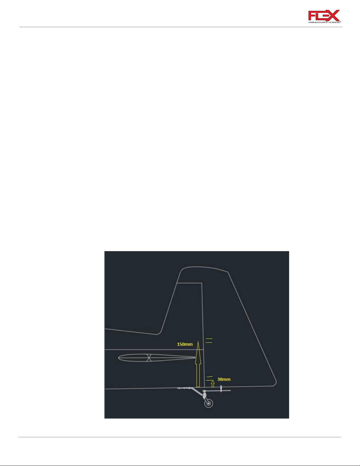
2. Select your rudder servo position and its corresponding control horn position. If using a
push-pull tail mounted rudder servo, remove the covering from the control horn slots at
the bottom of the rudder, only on the RIGHT side of the rudder. The lower of the two
control horn slot is 30mm from the bottom of the edge of the rudder.
If using a pull-pull rudder servo setup, remove the covering from the control horn slots
near the middle of the rudder on both sides of the rudder. The lower of the two slots
are located 150mm from bottom edges of the rudder.
!
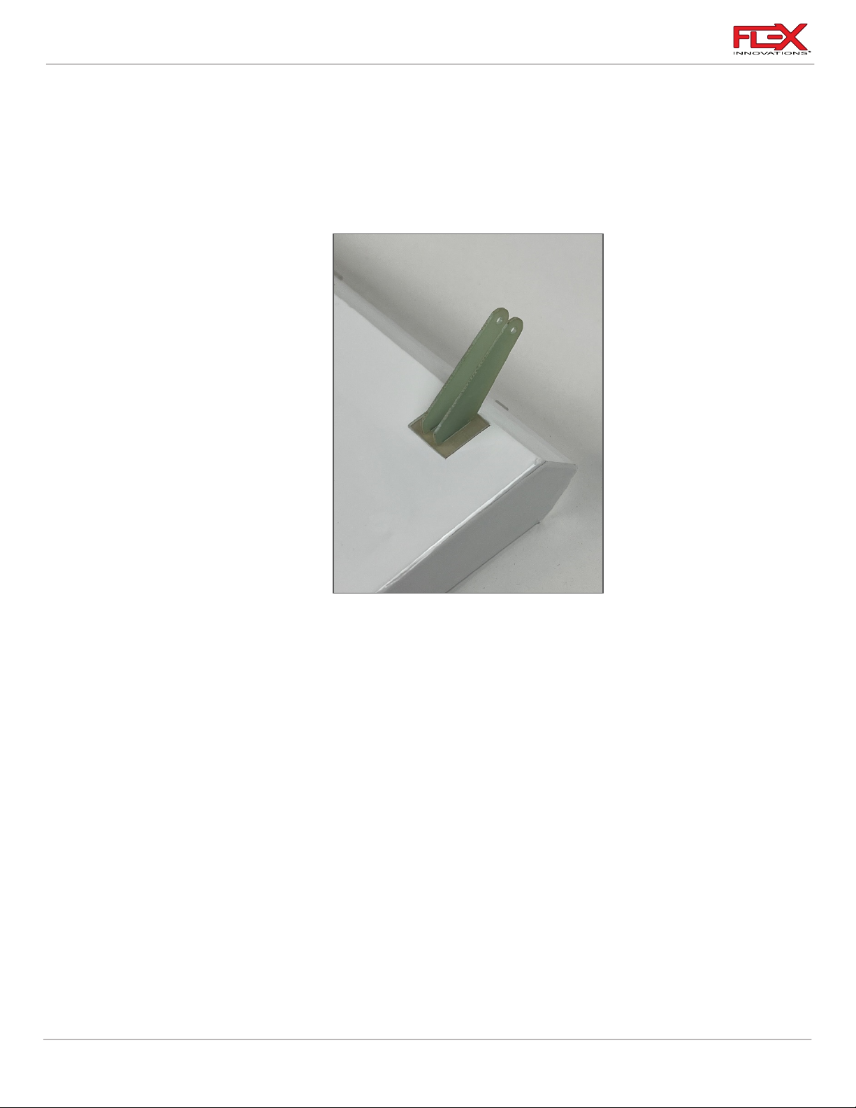
3. Prepare the control horns by sanding the portion of the control horn that extends into
the control surface with medium grit sandpaper. Use isopropyl alcohol and a paper towel
to clean the control horns and remove any excess debris from the control horn.
4. Slide the control horns through the square control horn base, and test fit them in their
corresponding slots. Note that the holes in the control horn base are offset. This is so that
the base does not extend over the hinge line. Adjust the holes in the control surfaces to
fit the control horns if needed.
5. Mark around the square control base. Use a very sharp hobby knife to remove the
covering where the square will be bonded to the control surface. Ensure that you don’t
cut too deep to avoid damaging the control surface under the covering.
6. Test fit the control horns into their corresponding slots in the rudder. Once satisfied with
the fit, mix an adequate amount of 30-minute epoxy, insert adhesive into the slots and
under the flat plate, then secure the control horns in place.
If using a pull-pull setup, repeat the process to glue the other control horn on the other
side of the rudder.
Ensure that the epoxy is copmpletely cured before you continue with the installation of
the servo and linkage(s).
45
Page 50
Cap 232EX 70cc Instruction Manual
!
!
!
!
!
Push-Pull Rudder Setup
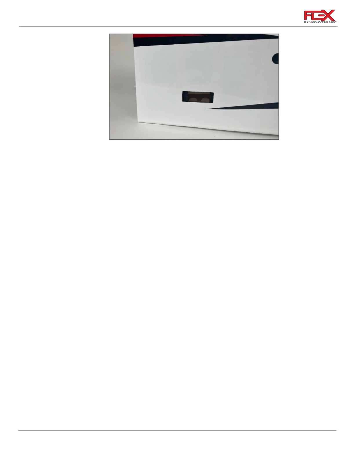
1. If you are using a tail-mounted push-pull rudder setup, locate the servo pocket in the
fuselage under the horizontal stabilizer. Use a #11 hobby knife to open the slot, then use
a covering iron to seal the covering into the slot. Do not cut the covering flush with the
edges, as you may risk the covering peeling up from airflow during flight. CUT THE
SERVO HOLE ON THE RIGHT SIDE OF THE FUSELAGE. THE LEFT SIDE DOES NOT HAVE
A SERVO TRAY, JUST AN OPENING IN THE SHEETING.
!
2. Thread a servo mounting screw into each of the pre-cut holes. Remove the screw and
apply thin CA to harden the threads cut by the screw. Let the CA fully cure before moving
forward.
3. Connect to the rudder servo a 36in servo extension cord. Use Servo clip, heat shrink or
thread to secure this connection.
4. Insert the other end of the servo extension in the long black tube and feed it through to
the end of the tube. The servo extension will exit near the rear tray. From there you can
connect it to your receiver.
5. Insert the rudder servo into the mounting location, and orient the servo so that the
output shaft is toward the nose. Mount the servo using the screws provided with your
servo.
46
Page 51
Cap 232EX 70cc Instruction Manual
!
!
!
!
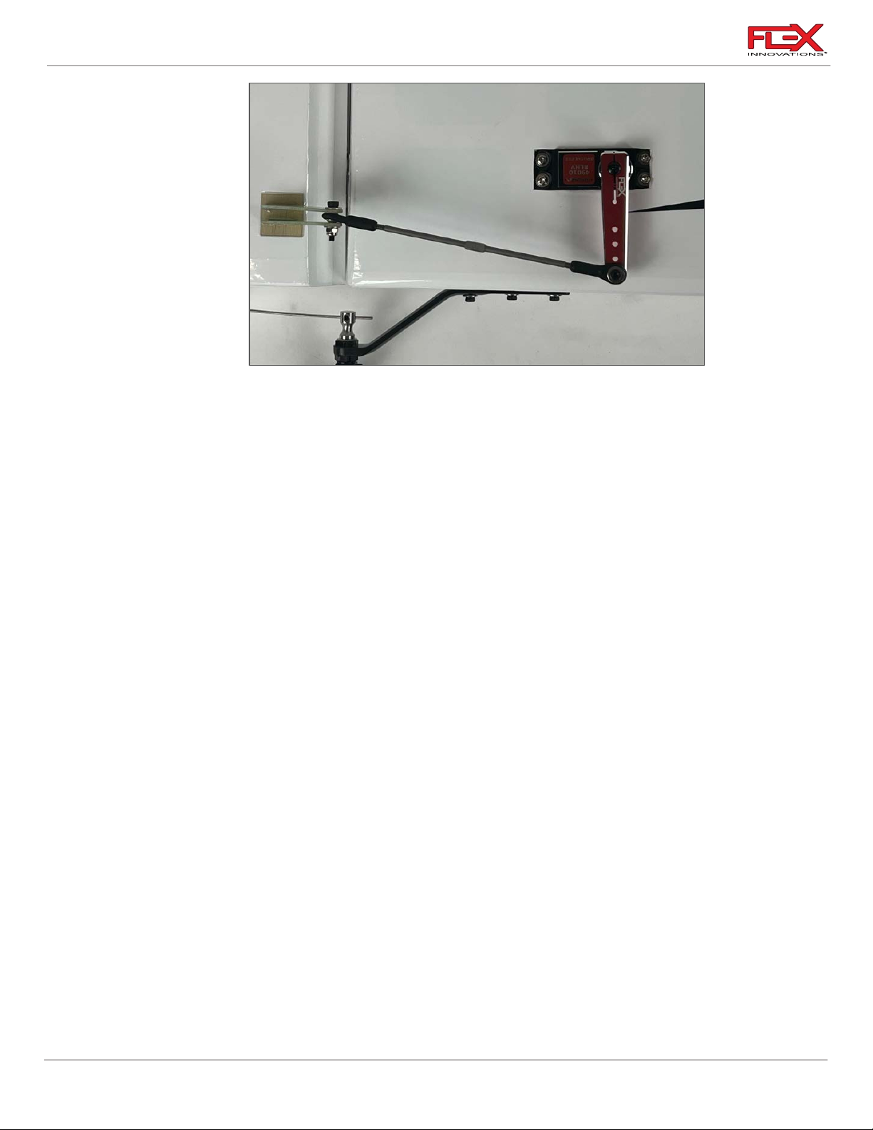
6. Assemble your specific linkages.
use a turnbuckle 5-1/8 in (136mm) long, and thread a ball link onto each end
approximately halfway. Mount the ball link to the bottom side of the rudder servo arm
(the side closest to the servo) in the 2-inch (51mm) hole location. On the servo arm side,
the order of components is as follows:
!
o M3x15 Socket Head Cap Screw
o M3 Washer
o Servo Arm
o Ball Link
o M3 Washer
o M3 Lock Nut
Mount the other end of the linkage to the control horn in the order noted below:
o M3 x 12 Socket Head Cap Screw
o M3 Washer
o Ball Link (with rigging coupler)
o Servo Arm
o M3 Washer
o M3 Lock Nut
7. Center the servo using your radio system. Install the servo arm so that it is perpendicular
to the servo case. Apply a small drop of blue thread locker to the servo arm screw and
secure it in place. If you are using a servo arm with clamping screws, apply a drop of blue
thread locker and secure that in place as well.
Pull-Pull Rudder Setup
1. If you are using a forward mounted pull-pull rudder setup, locate the servo pocket in the
fuselage under the canopy.
2. Thread a servo mounting screw into each of the pre-cut holes. Remove the screw and
apply thin CA to harden the threads cut by the screw. Let the CA fully cure before moving
forward.
47
Page 52
Cap 232EX 70cc Instruction Manual
!
!
!
!
3. Insert the rudder servo into the mounting location, and orient the servo so that the
output shaft is toward the tail. Mount the servo using the screws provided with your
servo.
4. Connect the servo to your receiver.
!
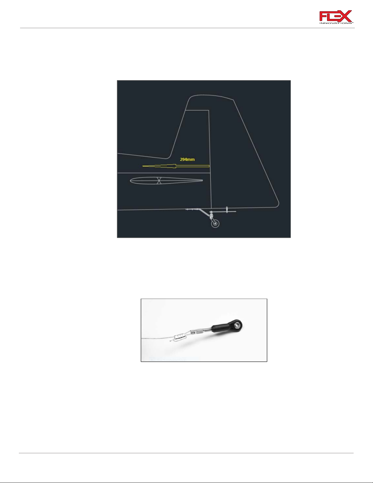
5. Locate the pull-pull cable exit holes in the rear of the fuselage. They begin approximately
294mm from the rudder hinge line and extend forward from the control horn position
QQ Pro Tip:
Use a soldering iron with a fine tip to open holes in the covering for things like the pull-pull wire exits
in the fuselage. Not only does this remove the covering, but it also seals it to the edges of the hole.
!
6. Using pliers, thread a rigging coupler approximately halfway into four ball links. On two
of the four ball links, take a section of pull-pull cable and route it through a small piece of
heat-shrink tubing, followed by a cable crimp. Then route the cable through the rigging
coupler and back through the crimp. For extra security, you can loop the cable around
the crimp a final time. Slide the crimp tight against the coupler and use a crimping tool to
permanently attach the cable. Apply a small amount of thin CA to aid in securing the
cable and crimp. Once secure, slide the heat-shrink tubing back over the cable and shrink
it in place. The heat-shrink tubing is only used to keep the cables looking neat and
prevent the wire from snagging on any objects. Repeat this process for the second cable.
48
Page 53
Cap 232EX 70cc Instruction Manual
!
!
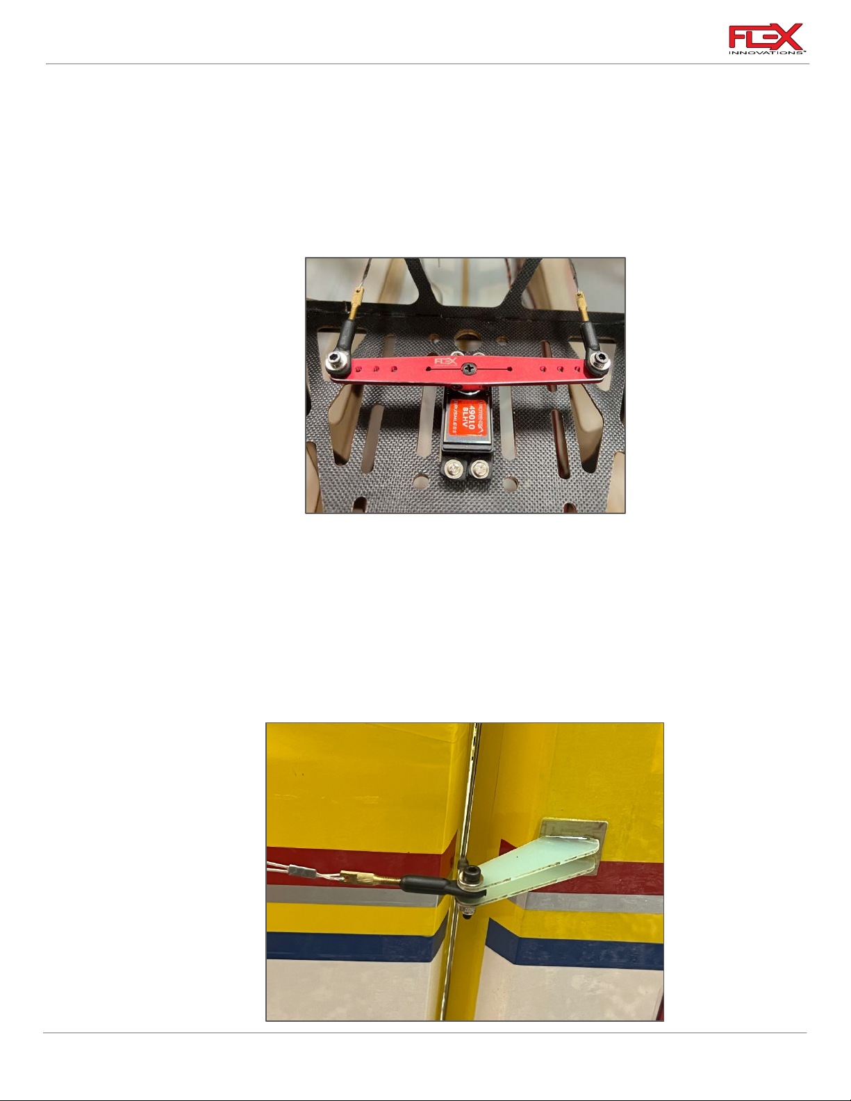
7. Attach a ball link and rigging coupler assembly to each side of the rudder servo arm at
the 2-inch hole location from the center of the arm. The order of hardware is as follows:
o M3x15 Socket Head Cap Screw
o M3 Washer
o Ball Link (with rigging coupler)
o Servo Arm
o M3 Washer
o M3 Lock Nut
!
8. Attach the remaining ball links and rigging coupler to each side of the rudder control
horn. The order of hardware is as follows:
o M3x15 Socket Head Cap Screw
o M3 Washer
o Fiberglass Control Horn #1
o Ball Link
o Fiberglass Control Horn #2
o M3 Washer
o M3 Lock Nut
49
!
Page 54
Cap 232EX 70cc Instruction Manual
!
!
Required for this section
Components
Tools
Adhesives/Building Materials
o Fuselage Assembly
o Left and Right Horizontal
Stabilizers
o Carbon Fiber Horizontal
Stabilizer Tube
o Anti-rotation carbon
fiber tube
o (2) 36in servo extension
o Servo Clip (FPMA1040)
!
!
9. Route the pull-pull cables through the fuselage, being sure to keep them from tangling
with any formers or other structure in the aircraft. The cables should remain straight and
should not cross before they exit the fuselage. Route the cables through a piece of heat
shrink and through a crimp before routing them through the rigging coupler. Route the
cable back through the crimp and get the cables as tight as possible with the rudder
centered before crimping the cables. Crimp the cables. trim any excess cable, and cover
with heat-shrink if desired.
10. To tighten the pull-pull cables, remove a ball link from the control horn and thread the
rigging coupler deeper into the ball link. For your initial flights, you’ll want to set the
tension tight, as the cables will loosen slightly during the first several flights.
MOUNTING THE STAB
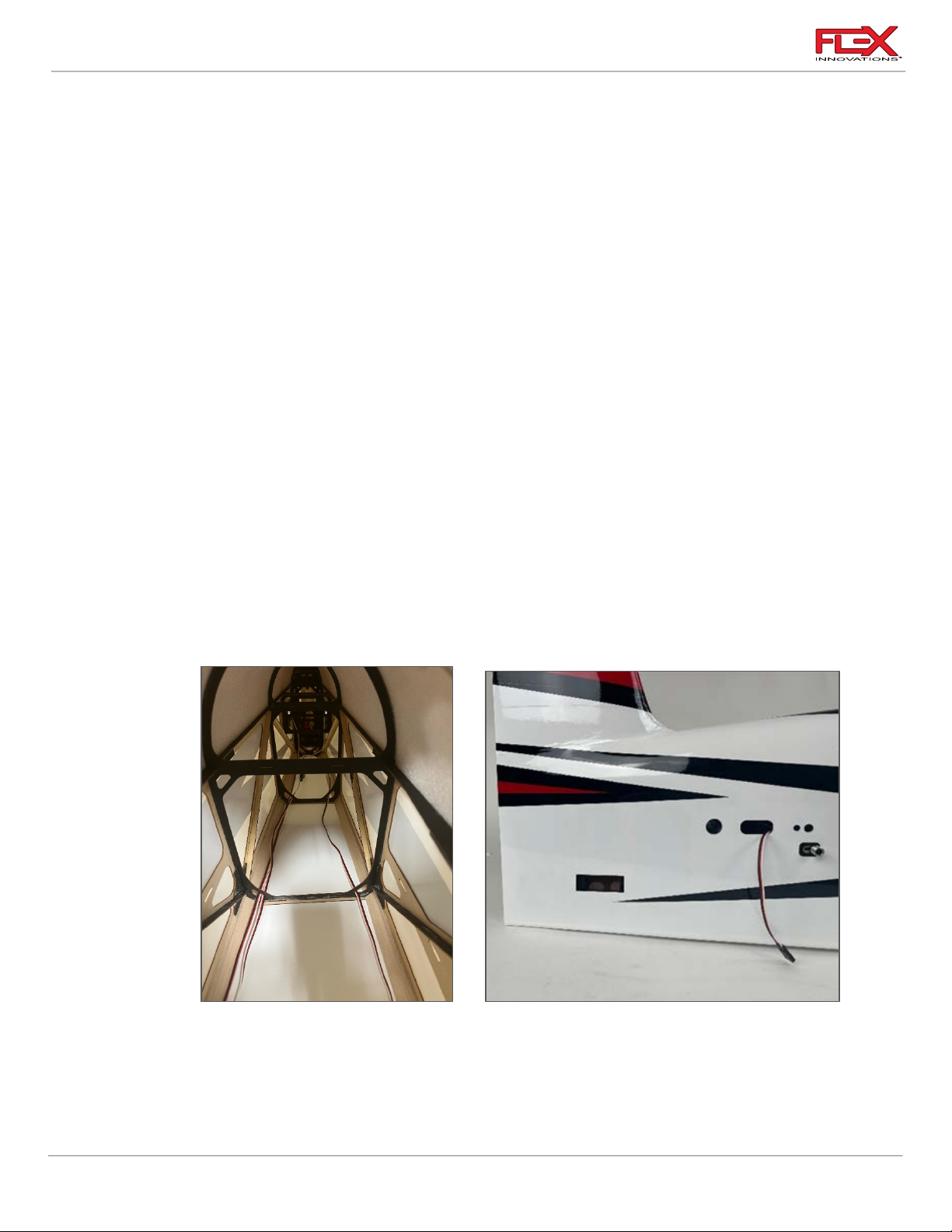
1. Route the 36-inch (92mm) elevator servo extensions through the botom openings in the
50
fuselage as shown in the picture above.
2. Insert the carbon fiber horizontal stab tube and carbon fiber antirotation tube into the
appropriate holes in the fuselage and approximately center them left to right.
!
Page 55
Cap 232EX 70cc Instruction Manual
!
!
3. Slide the Right-side horizontal stabilizer onto the carbon tubes, connect the servo to the
servo extension and feed the excess servo wires into the fuselage.
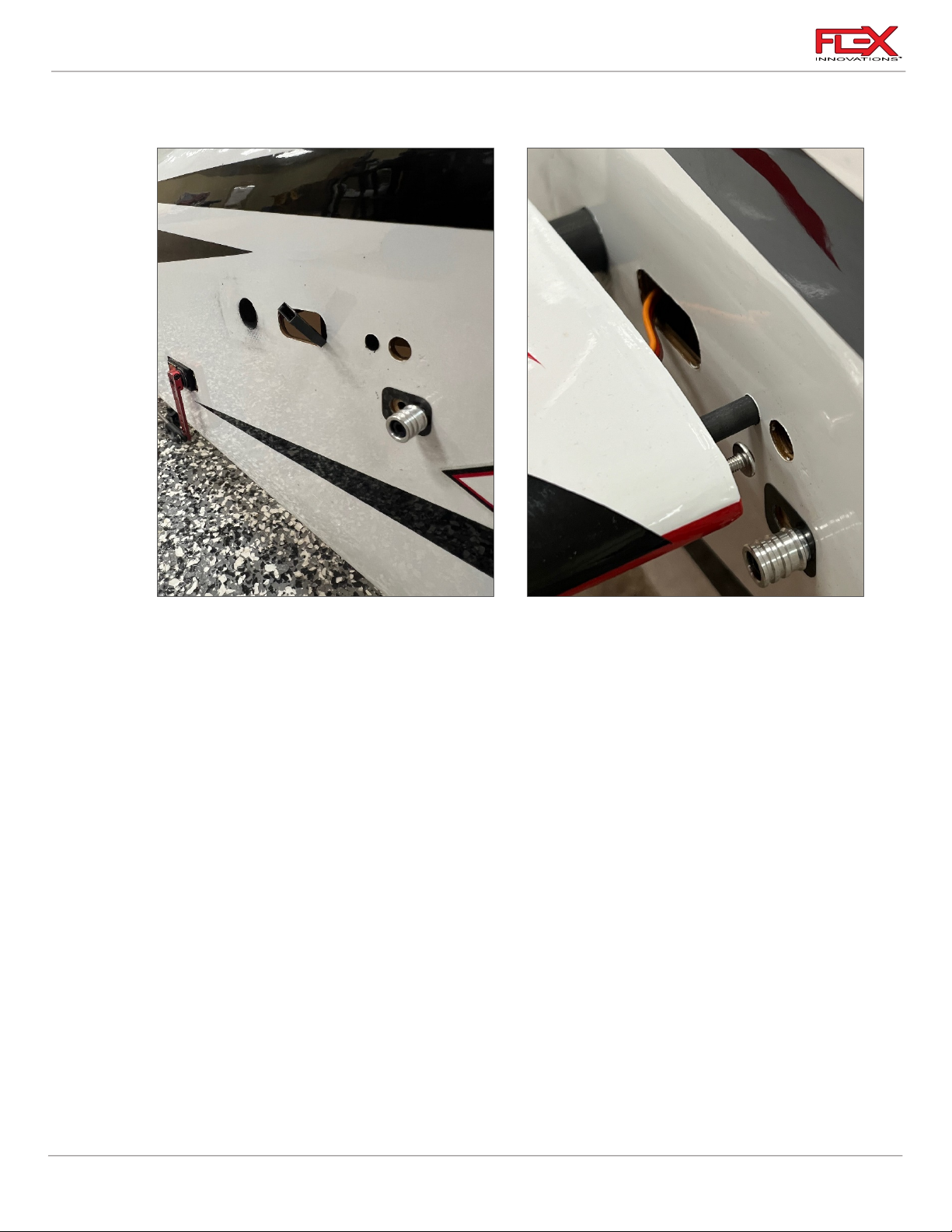
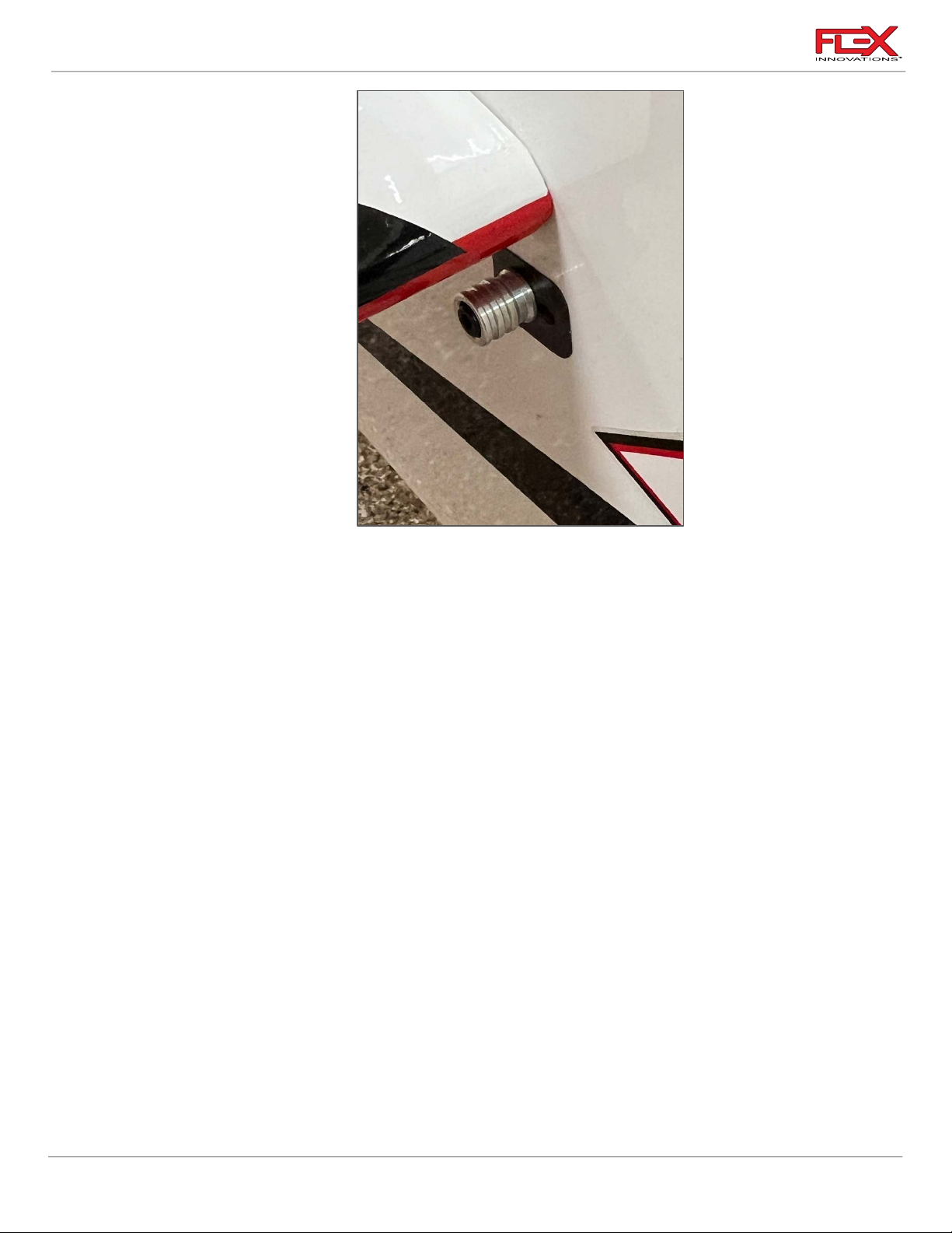
4. Unlock the Flex Speed-Lock mechanism by pulling on the knob away from the fuselage
and sliding forward until it reaches its stop. Place the stab in place and lock the Flex
Speed-Lock. To lock all that is required is to slide the knob backwards until it “clicks”. Test
the knob ad the stab to make sure they are properly locked in place.
!
51
Page 56
Cap 232EX 70cc Instruction Manual
!
Required for this section
Components
Tools
Adhesives/Building Materials
o Fuselage Assembly
o Receiver
o Receiver Switch
o Aura 8 or 12 Professional
(Optional)
o Receiver Batteries
o Hook and Loop Straps
o Adhesive-Backed Hook
and Loop Tape
o Tie-Wraps
o #1 Phillips Screwdriver
o Hobby Knife with #11
Blade
Thin CA
5. Repeat for the Left side horizontal Stabilizer.
RADIO INSTALLATION
IT IS IMPORTANT TO UNDERSTAND THAT THIS AIRCRAFT DOES NOT REQUIRE AURA OR ANY
OTHER FLIGHT STABILIZATION SYSTEM TO PERFORM AT ITS HIGHEST POTENTIAL. THE AURA
OR OTHER FLIGHT STABILZATION IS AN OPTION CHOOSEN BY THE PILOT TO MAKE FLYING
ANY AIRCRAFT EASIER OR MORE ENJOYABLE BUT IT WILL NOT UNLOCK ANY ADDITIONAL
PERFORMANCE OR CHARACTERISTIC OTHER THAN WHAT IS ALREADY INHERENT TO THE
AIRCRAFT DESIGN. FLEX INNOVATIONS RECOMMENDS THAT YOU FLY THE AIRPLANE WITH
YOUR FAVORITE SET UP, WHETHER THIS IS WITH OR WITHOUT AN AURA OR OTHER FLIGHT
STABILIZATION.
52
!
Page 57
Cap 232EX 70cc Instruction Manual
!
!
!
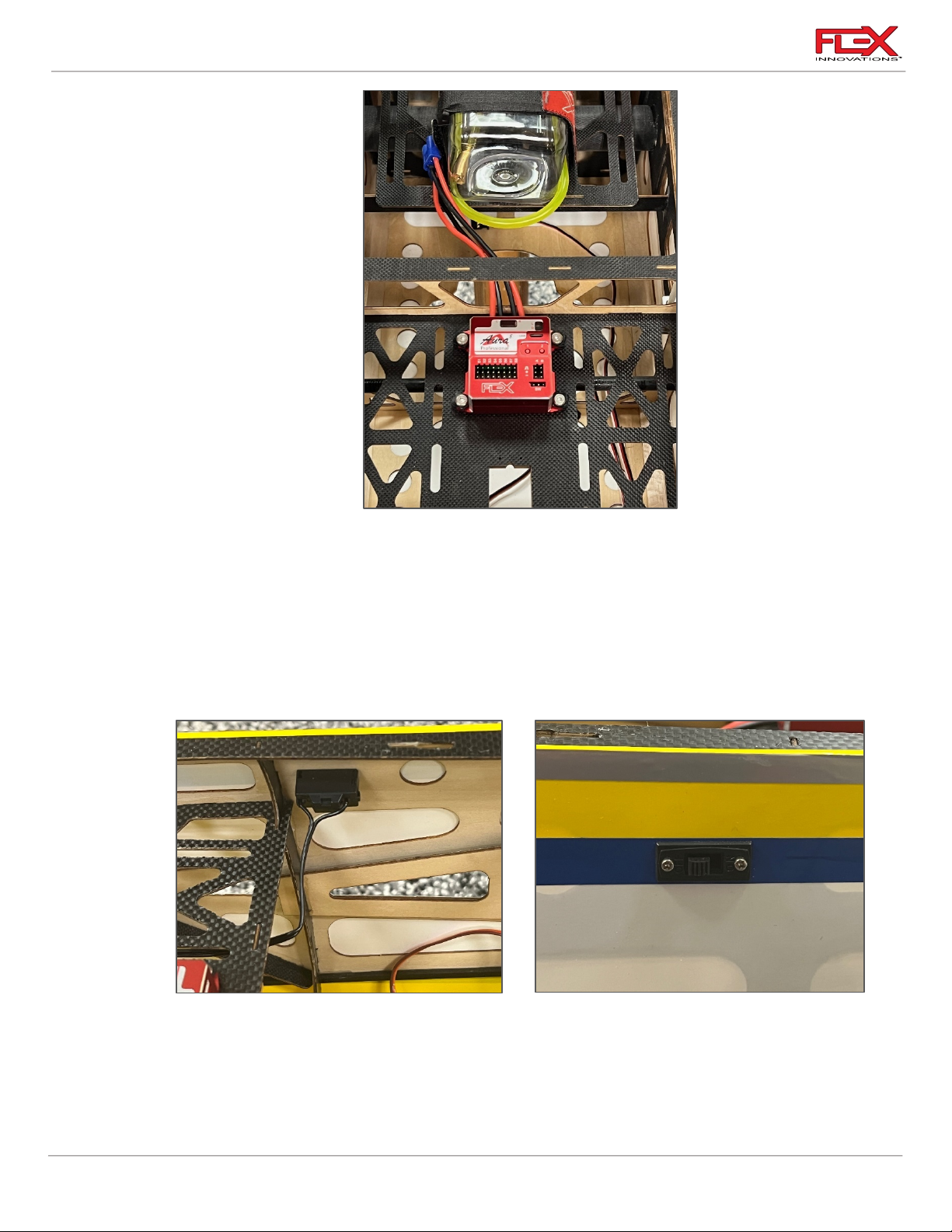
1. If you are using the Aura 8 or 12 Professional AFCS, it should be mounted forward of the
rudder servo location in the center of the fuselage as shown in picture above. The Aura
program for the Cap 232EX 70cc can be found in the Aura Config Tool Windows
application.
Use a #1 Phillips screwdriver to thread an Aura mounting screw into each of the pre-cut
holes in the mounting tray. Remove the screw and apply a small amount of thin CA to
each of the holes to harden the threads cut by the screw. Let the CA fully cure before
mounting the Aura and securing the (4) screws.
2. Locate the RX or Aura switch just under the canopy. Note that there are switch locations
on both sides of the fuselage. Remove the covering from the hole of your choice using a
hobby knife with a #11 blade and install your RX switch. Use blue thread lock if your
switch uses screws with metal-to-metal contact. DO NOT use thread lock if your screws
thread into plastic!
53
!
Page 58
Cap 232EX 70cc Instruction Manual
!
!
Required for this section
Components
Tools
Adhesives/Building Materials
o 2) Wing Fairing
o Hobby Knife with #11 Blade
Thin CA
!
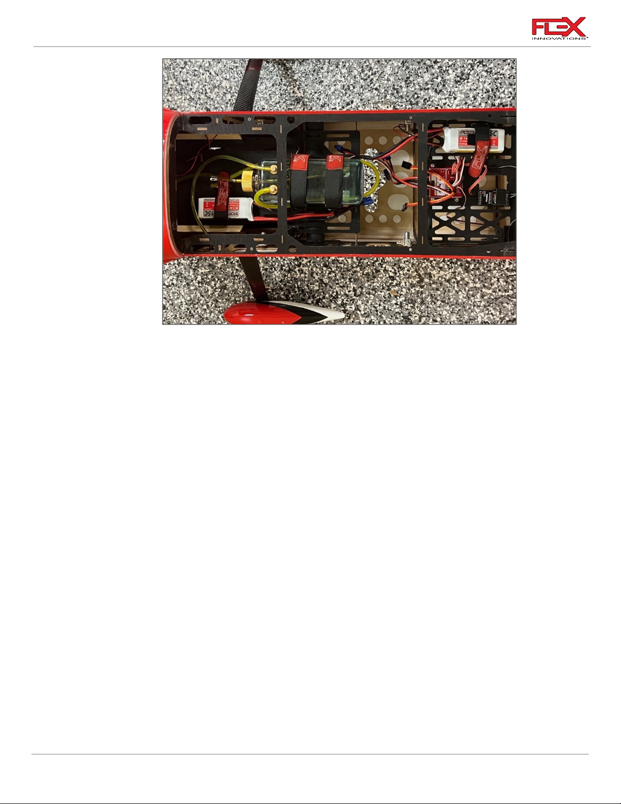
3. Make all the necessary servo connections. Depending on the center of gravity (see the CG
section), install your (2) receiver batteries in one of two mounting locations provided in
the Cap 232EX 70cc. They are located as follows:
Use adhesive-backed hook and loop tape and a hook and loop strap to secure each
battery in place.
4. Place your receivers in the appropriate area according to your receiver’s instruction
manual.
Note: If you choose to use Aura 8 Professional AFCS, you can find the Cap 232EX 70cc
Aura setup in the Aura Config Tool by going to File > New Aura Config File Wizard.
INSTALL THE WING FAIRING
54
Page 59
Cap 232EX 70cc Instruction Manual
!
!
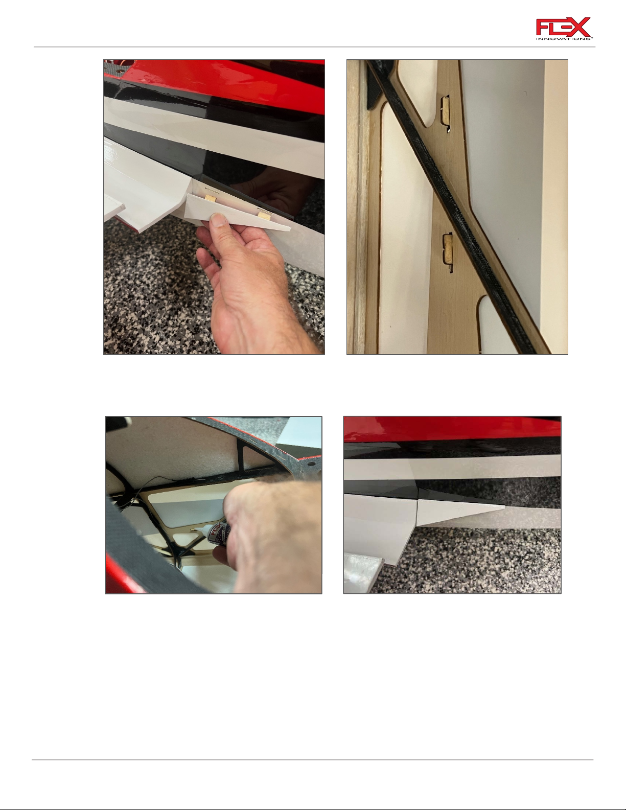
1. The wing fairings are installed just rear of the wings where they meet the fuselage. If the
mounting slots are not open, use a hobby knife to cut two slots in the fuselage. Test fit
the wing fairings and make any adjustments as necessary.
2. To fix the fairings in place use thin CA and apply it from inside of the fuselage to the two
tabs on each of the fairings.
!
!
55
Page 60
Cap 232EX 70cc Instruction Manual
Required for this section
Components
Tools
Adhesives/Building Materials
o Fuselage Assembly
o Main Wings (2)
o Anti-rotation Tube
o Main wingTube
o Canopy Hatch
o SFG
o (4) M3 White Thumb Screws
!
FIELD ASSEMBLY
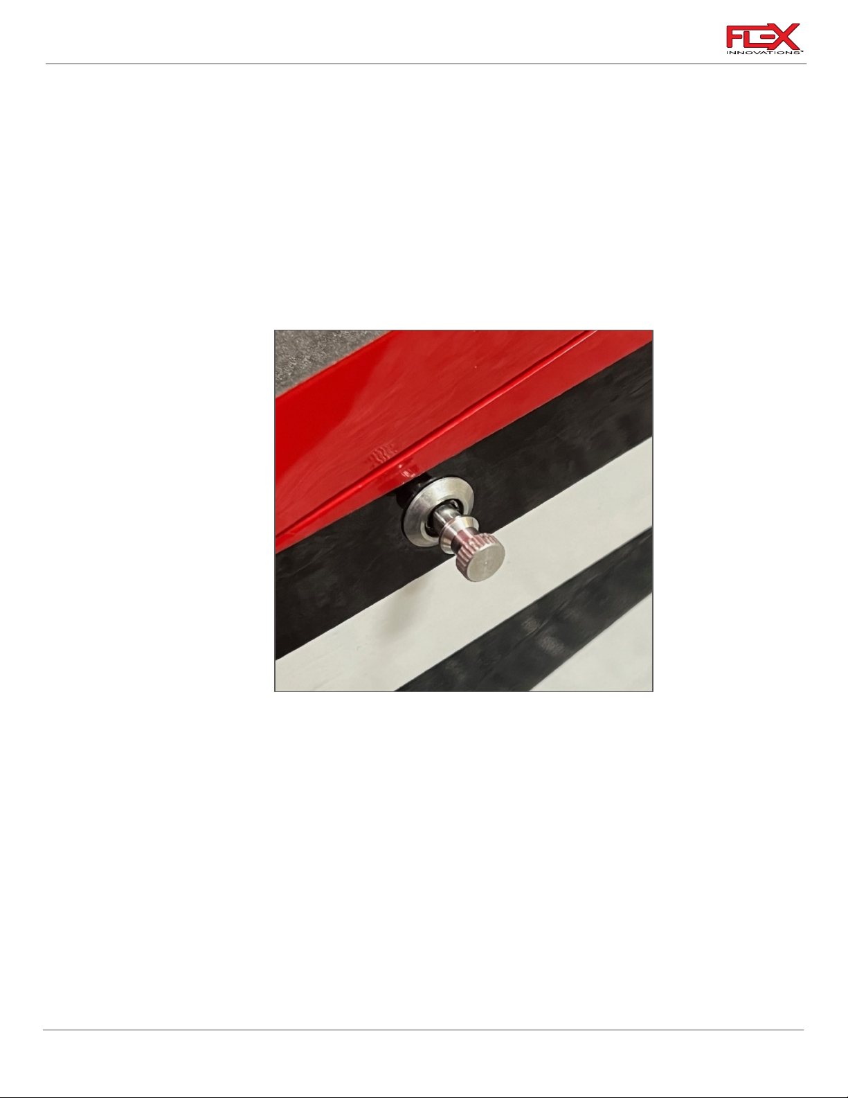
1. Pull out the Flex Canopy Speed-Lock knob until it bottoms out, then twist it CW or CCW
1/4 turn. You can now release the knob and it will stay in unlocked position (canopy
open). Do the same to the Flex Canopy Speed-Lock on the other side of the fuselage.
Proceed and lift the canopy from the rear at a shallow angle and pull back at same time
until the two front canopy pins are out of their holes.
56
!
Page 61
Cap 232EX 70cc Instruction Manual
!
!
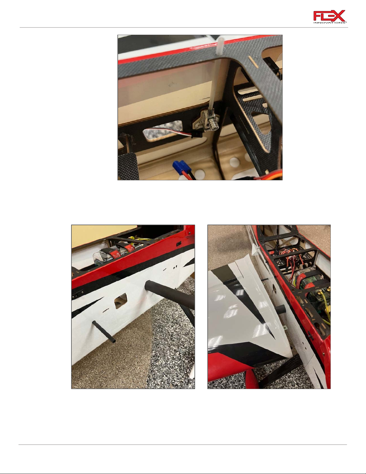
2. Unlock the 4 wing Flex Speed-Locks from both right and left side. To unlock them you
need to pull out on the knob and then slide it up until it reaches its limit. Note that the
Flex Speed-Lock design has a plastic tube extension on the top that shows the unlock
position when the tube is sticking out of the top of the airplane frame.
!
! !
3. Slide the main wing tube and the anti-rotation tube into the fuselage so that they are
roughly centered left to right. Slide one of the wing panels over the tube, connect the
aileron servo to the servo extension and fully slide the wing against the fuselage, feed the
excess wire into either the wing or the fuselage, until you see no gap between the wing
and the fuselage.
57
Page 62
Cap 232EX 70cc Instruction Manual
!
!
!
!
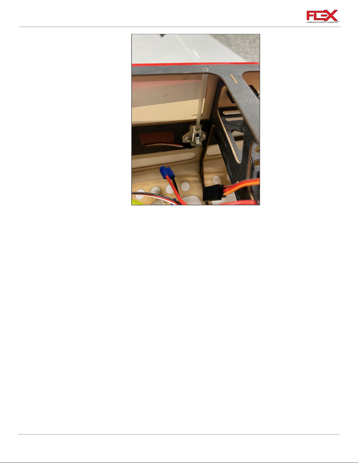
4. Proceed to lock the Flex Speed-Locks by pushing down on the plastic tubes until they are
flush with the fuselage, and you hear a “click”. If the plastic tube is not flush with the top
of the fuselage, then you know the Flex Speed-Lock is not properly locked. The
protruding tube will also prevent the canopy from being installed when the Flex SpeedLocks are not fully locked.
Note: it is not recommended to lock the Flex Speed-Lock by pulling on handle and sliding
it down as this does not guarantee that the knob will find the indentation and be in the
proper locked position. Pushing on the tube and hearing the “click” is what ensures that
it is locked properly.
5. Repeat for the second wing.
Always push down on the plastic tubes until you hear “click” and they sit flush with
the fuselage frame.
Make sure you lock all 4 Flex Speed-Locks.
6. Install the canopy hatch by inserting the two front pins in the fuselage and seat flush to
the fuselage. One in place, then proceed to lock the canopy. Turn the Flex Canopy SpeedLock knob ¼ turn CW or CCW and the knob will go in a find lock position. Do the same
with the other side. Check that the Flex Speed-Locks are in the locked position by pulling
up on the canopy to confirm that it is secure.
58
Page 63
Cap 232EX 70cc Instruction Manual
!
!
!
!
!
!
!
!
!
!
Side Force Generators Installation (optional)
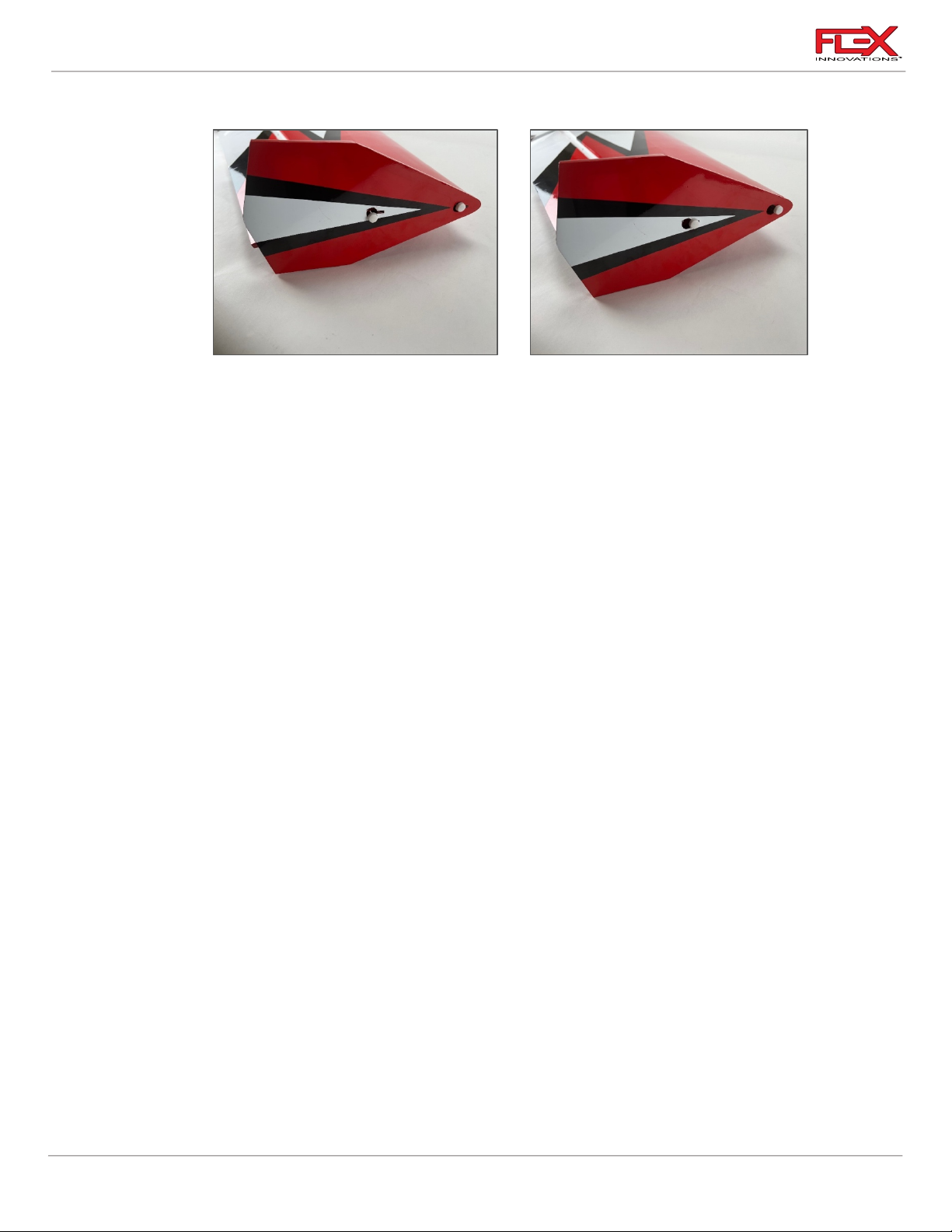
1. First install the two White Thumb Screws provided onto the wingtip of the wing panel.
Screw them on only a few turns leaving plenty of space. Insert the SFG over the thumb
screws through the large round holes. Once seated against the wing tip, slide the SFG
backwards until the thumb bolts reach the front edge of the provided slot. Proceed to
tighten both bolts with your thumbs.
2. Repeat this sequence on the other wing panel.
!
DECAL INSTALLATION
A traditional set of decals is provided with the QQ Cap 232EX 70cc. However, if you want the very
best finished appearance, we recommend the Premium Vinyl Graphics Kit made by Callie Graphics
and sold by Flex Innovations. The part numbers are listed in the optional parts table.
Use the drawings provided below for a guide to apply the decals to your model.
1. Thoroughly clean the model to ensure it is free of oil, fingerprints, and dust.
2. Separate the decals, but do not remove the paper backing.
3. Prepare a dishpan or small bucket with a mixture of warm water and liquid dish
detergent. The ratio should be approximately one teaspoon per gallon of water.
4. Submerse the decal into the water/soap mixture and gently remove the paper backing.
Removing the backing under water prevents fingerprints from being visible on the back
side of the decal.
5. Apply some water/soap mixture with your palm to the area desired. Once the area is
saturated, position the decal on the airplane. Even though these are not water transfer
decals, using wet application methods allows the decal to be repositioned, reduces
bubbles, and eliminates fingerprints and other blemishes from being visible.
6. Hold the decal in place and use a paper towel to gently wipe most of the water away.
7. Use a soft piece of balsa, or similar, to squeegee out the remaining liquid from
underneath the decal.
8. Repeat the process until all decals are applied. Do not move, or otherwise touch the
model for at least 24 hours to allow adequate time for the remaining water to evaporate.
59
Page 64
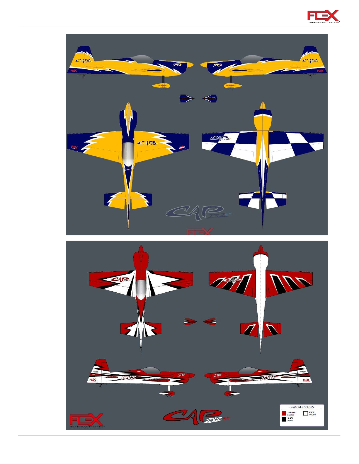
Cap 232EX 70cc Instruction Manual
!
60
!
Page 65
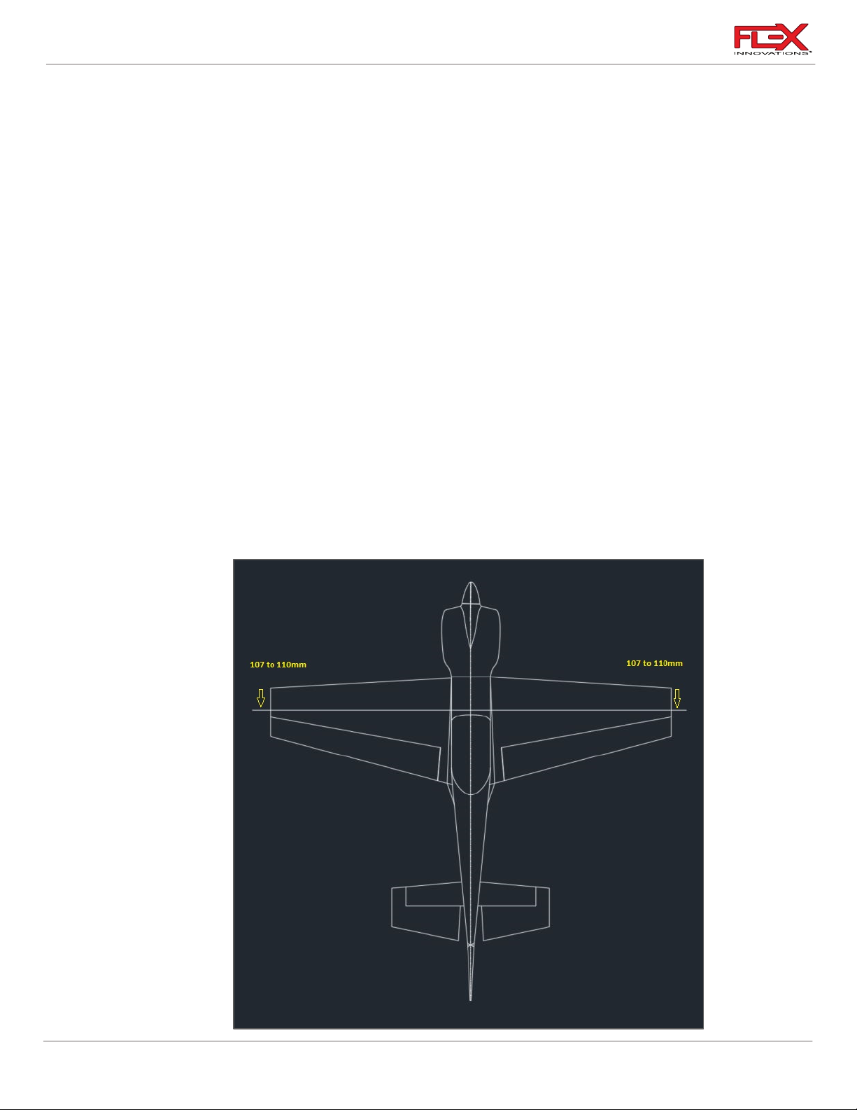
Cap 232EX 70cc Instruction Manual
FINAL SETUP AND FLYING NOTES
CENTER OF GRAVITY
Setting the center of gravity (CG) is one of the most important steps for success, particularly with a
new airplane. The Flex Innovations Cap 232EX 70cc in particulary, is very sensitive to the CG. It is
highly recommended to stay within the range provided to achieve the most performace and least
coupling. The Cap 232EX 70cc is a very enjoyable aircraft to fly, but if the CG is not within an
acceptable range, it will make the airplane not track and perform to its maximum capability.
Before checking the CG of your model, ensure that all the components are installed in your airplane.
This means the batteries, servos, linkages, hardware, propeller, spinner, hatches; everything. The
airplane must be in ready-to-fly condition (without fuel), otherwise the measurement will not be
accurate. In the case of electric setup measure CG with flight and receiver packs installed.
There are several methods for determining center of gravity, from using a CG machine, to using
fingers and a friend. Regardless of the method used, ensure that the tests are accurate and
repeatable. If there are any inconsistencies between measurements, work to isolate the source of the
error(s) making sure that the test can be repeated with the same results.
The range of the center of gravity for the Cap 232EX 70cc is 107mm to 110mm AFT from the
LEADING EDGE of the WING an at wing tip. It is critical that the starting point for your model be
at this point. This measurement is determined from many test flights by designer and World
Champion Quique Somenzini.
61
!
Page 66
Cap 232EX 70cc Instruction Manual
Cap 232EX 70cc Control Throws and Expos
Low Rate
High Rate
Up
Down
Up
Down
Aileron
20.5
20
38
37
Elevator
11
11
60+
60+
Rudder
25
25
Maximum Available
Maximum Available
Aileron Expo
35%
35%
45%
45%
Elevator Expo
25%
25%
50%
50%
Rudder Expo
25%
25%
45%
45%
QQ Pro Tip:
o 107mm to 110mm aft from the leading edge at the wingtip is the best CG location for flying
the Cap 232EX 70cc, and where all tweaks to the airframe have been made.
AURA 8 PROFESSIONAL
If you choose to use Aura 8 Professional AFCS, you can find the information on the Cap 232EX 70cc
Aura set-up in the Aura Config Tool and in the wiki at:
https://wiki.flexinnovations.com/wiki/Cap_232EX_70cc
STARTING CONTROL SURFACE THROWS AND EXPONETIAL
The following throws and exponential have been tested thoroughly during the development of the
airplane and have been determined to be the optimal starting point for the Cap 232EX 70cc. As you
become more familiar with the airplane, you may tweak the rates and expos to better suit your flying
style, but these numbers provide a very good starting point.
NOTE: Throws are measured in degrees. We recommend you download an App on your phone to
measure degrees. Since expo directions vary by transmitter manufacturer, all expos listed below
are those that make the control feel softer around the stick's center position.
QQ Pro Tips:
o High rate should be reserved for XA/3D aerobatics
o The low rate noted in the chart above includes enough aileron throw to do snap rolls. If you
o For high rudder rate, increase the travel until the control horn nearly touches the fuselage,
o If you are looking for the maximum roll rate at high airspeeds, we recomment that you do not
62
are sensitive to the ailerons you can back down a little.
and be sure to match both directions.
increase the high rate aileron deflections more than what is noted above as we have found
that it creates too much drag and will actually slow down the roll rate.
Page 67

Cap 232EX 70cc Instruction Manual
!
!
!
!
!
!
!
RANGE TESTING
Carefully follow the binding and range testing instructions included with your radio equipment. If
there are any issues passing the test range, please consult your transmitter and receiver manuals or
contact your transmitter and receiver manufacturer to determine the appropriate solution before
attempting to fly.
BEFORE FIRST FLIGHT
Before going to the field for your first flight, please go over the finished, fully assembled model at
home. The key to a successful first flight is preparation and ensuring that your plane is airworthy.
1. For optimal performance of your model, balance your propeller and spinner. Most
propellers are balanced fairly-well out of the package; however, some fine-tuning can
make a mediocre propeller perform great. An out-of-balance propeller or spinner can
wreak havoc on the electronic components in the airplane, as well as prematurely
shorten the life span of the engine, servos or even the model itself. A balanced propeller
will be quieter, generate more thrust, produce less vibration, and operate more efficiently
than one that is not balanced.
2. Re-check all linkages and connections, including those that may have been assembled by
the factory. Ensure pushrods are sufficiently threaded into ball links, ensure that all metalto-metal connections have thread lock applied and ensure that all control surfaces move
freely and in their proper direction.
3. Verify proper functioning, break-in, and operation of your engine choice. Ensure that the
fuel-air mixture is correct, and that the engine is producing full power. If you are not
familiar with gas engines, ask for the assistance of a more experienced pilot in your area
or speak with your engine manufacturer.
4. Secure any loose wiring inside the fuselage or wings in such a way that they do not rub or
chafe.
5. Ensure that all batteries (transmitter, receiver, ignition, or flight packs) are fully charged
prior to leaving for the flying field.
6. Take a few moments to assemble the airplane away from commotion, talkative
onlookers, or any other distractions. Ensure that all connections are properly made and
secured, the Flex Speed-Locks are securely locked. Take a few minutes to plan out your
first flight.
7. If your gas engine is new, avoid prolonged full throttle runs and vertical climbs. Limit the
first few flights to a short flight time. Start off short, gradually lengthening the flight times
as you become comfortable with the performance of your engine. Six minutes is a good
time to limit your first flights to. As you become more familiar with the airplane and begin
to fly it in a more aggressive manner, monitor the temperature of the engine and adjust
the fuel-air mixture according to your engine manufacturer’s recommendations.
63
Page 68

Cap 232EX 70cc Instruction Manual
AMA SAFETY CODE
When flying your aircraft, we recommend following the guidelines set by the Academy of Model
Aeronautics (AMA). You can find their Safety handbook as well as more information on the AMA at
their website, located at the address below.
https://www.modelaircraft.org/
64
Page 69
Cap 232EX 70cc Instruction Manual
FPM2300A
Cap 232EX 70CC ARF Red
FPM2300B
Cap 232EX 70CC ARF Yellow
FPM2350A
Cap 232EX 70CC ARFSV Red
FPM2350B
Cap 232EX 70CC ARFSV Yellow
FPM2301A
Cap 232EX 70cc Fuselage, Red
FPM2301B
Cap 232EX 70cc Fuselage, Yellow
FPM2302LA
Cap 232EX 70cc Left Wing, Red
FPM2302LB
Cap 232EX 70cc Left Wing, Yellow
FPM2302RA
Cap 232EX 70cc Right Wing, Red
FPM2302RB
Cap 232EX 70cc Right Wing, Yellow
FPM2303A
Cap 232EX 70cc Horizontal Stabilizer Set, Red
FPM2303b
Cap 232EX 70cc Horizontal Stabilizer Set, Yellow
FPM2304A
Cap 232EX 70cc Rudder, Red
FPM2304B
Cap 232EX 70cc Rudder, Yellow
FPM2305A
Cap 232EX 70cc 2-piece Cowling, Red
FPM2305B
Cap 232EX 70cc 2-piece Cowling, Yellow
FPM2306A
Cap 232EX 70cc Canopy Hatch, Red
FPM2306B
Cap 232EX 70cc Canopy Hatch, Yellow
FPM2307
Cap 232EX 70cc Carbon Fiber Landing Gear
FPM2308A
Cap 232EX 70cc Wheel Pant Set, Red
FPM2308B
Cap 232EX 70cc Wheel Pant Set, Yellow
FPM2309
Cap 232EX 70cc Carbon Fiber Wing & Stab Tubes
FPM2312
Cap 232EX 70cc Linkage and Control Horn Set
FPM2313
Cap 232EX 70cc Hardware Set
FPM2315A
Cap 232EX 70cc Decal Sheet, Red
FPM2315B
Cap 232EX 70cc Decal Sheet, Yellow
FPM2317
Cap 232EX Main Wheels with Axle (plastic hub)
FPM2321
Cap 232EX 70cc Laser Cut Wood Parts
FPM2326
Cap 232EX 70cc Engine Baffle Kit
FPM2327A
Cap 232EX 70cc Pilot and Cockpit Set, Red
FPM2327B
Cap 232EX 70cc Pilot and Cockpit Set, Yellow
FPM2333B
Cap 232EX 70cc Horizontal Stabilizer, Yellow
FPMA1030
Flex 4" Spinner back plate
FPZA1054
Flex Canopy Speed-Lock
REPLACEMENT PARTS
65
Page 70
Cap 232EX 70cc Instruction Manual
FPZA1055
Flex Speed Lock Set of 4 (Cap 232EX 70cc)
FPM2329A
Premium Vinyl Graphics, Cap 232EX 70cc, Red
FPM2329B
Premium Vinyl Graphics, Cap 232EX 70cc, Yellow
FPM2314
Cap 232EX 70cc Premium Wing & Tail Bag Set
FPM2327A
Cap 232EX 70cc Pilot and Cockpit Set, Red
FPM2327B
Cap 232EX 70cc Pilot and Cockpit Set, Yellow
FPMDA70
Desert Aircraft DA-70cc Engine
FPMDA70MUFLR
DA70 Muffler
FPMGP76
GP 76cc V2 Engine with Mufflers
FPMA1031
4 inch Carbon Fiber Spinner, Edge Style, Red
FPMA1032
4-inch Carbon Fiber Spinner, Edge Style, Yellow
FPM2019
700cc Lightweight Fuel/Smoke Tank
FPMPF2409
Flex 24x9Carbon Fiber Propeller
FPZA1036
Aluminum Servo Arm 2-in Clamping (25T)
FPZA1037
Aluminum Servo Arm 4-in Clamping (25T)
FPZA1040
Servo Connector Safety Clip
FPZAURA08PRO
Aura 8 Professional AFCS
FPZAURA12PRO
Aura 12 Professional AFCS
FPZBR20002S15
2000 mAh 2s 15C JR/EC3 Connector RX Li-Po Battery Pack
FPZDS49010BLHV
Potenza DS49010BLHV Brushless Servo
FPMAMCFUELER
McFueler Fuel Dot
FPMA1033
Flex Aircraft Sun Shade 70cc Monoplane
FPM1124
15mm Aluminum Stand Off
FPMHOLYG2
Holy Smokes G2 Smoke System
OPTIONAL ACCESSORIES
66
Page 71

Cap 232EX 70cc Instruction Manual
LIMITED WARRANTY
Warranty Coverage
Flex Innovations LLC and its authorized resellers (“Flex”) warrant to the original purchaser that this
product (the “Product”) will be free from defects in materials and workmanship at the date of
purchase.
Outside of Coverage
The warranty is not transferable and does not cover:
(a) Products with more than 45 days after the purchase date
(b) Damage due to acts of God, accident, misuse, abuse, negligence, commercial use, or due to
improper use, installation, operation, or maintenance
(c) Damage to other components or assemblies associated with the use of the Product.
(d) Modification of or to any part of the Product
(e) Product not purchased from an authorized Flex Innovations dealer or distributor.
(f) Product that has been partially, or fully assembled
(g) Shipping damage
(h) Cosmetic damage
(i) Services or labor associated with the repair, use or assembly of the Product.
OTHER THAN THE EXPRESS WARRANTY ABOVE, FLEX MAKES NO OTHER WARRANTY
REPRESENTATION, AND HEREBY DISCLAIMS ALL IMPLIED WARRANTIES, INCLUDING, WITHOUT
LIMITATION, THE IMPLIED WARRANTIES OF NONINFRINGEMENT, MERCHANTABILITY AND FITNESS
FOR A PARTICULAR PURPOSE. THE PURCHASER ACKNOWLEDGES THAT THEY ALONE HAVE
DETERMINED THAT THE PRODUCT WILL SUITABLY MEET THE REQUIREMENTS OF THE
PURCHASER’S INTENDED USE.
Purchaser’s Remedy
Flex’s sole obligation and purchaser’s sole and exclusive remedy shall be that Flex will, at its option,
either (i) service, (ii) replace any part of the Product determined by Flex to be defective, or (iii) replace
the Product determined by Flex to be defective. Flex reserves the right to inspect all Product(s)
involved in a warranty claim. Service or replacement decisions are at the sole discretion of Flex. Proof
of purchase is required for all warranty claims. SERVICE OR REPLACEMENT AS PROVIDED UNDER
THIS WARRANTY IS THE PURCHASER’S SOLE AND EXCLUSIVE REMEDY.
Limitation of Liability
FLEX SHALL NOT BE LIABLE FOR SPECIAL, INDIRECT, INCIDENTAL OR CONSEQUENTIAL
DAMAGES, LOSS OF WAY, REGARDLESS OF WHETHER SUCH CLAIM IS BASED IN CONTRACT,
WARRANTY, TORT, NEGLIGENCE, STRICT LIABILITY OR ANY OTHER THEORY OF LIABILITY, EVEN
IF FLEX HAS BEEN ADVISED OF THE POSSIBILITY OF SUCH DAMAGES.
Further, in no event shall the liability of Flex exceed the individual price of the Product on which
liability is asserted. As Flex has no control over use, setup, assembly, modification or misuse, no
liability shall be assumed nor accepted for any resulting damage and/or injury. By the act of use,
setup or assembly, the user accepts all resulting liability. If you as the purchaser or user are not
prepared to accept the liability associated with the use of the Product, purchaser is advised to return
the Product immediately in new and unused condition to the place of purchase.
67
Page 72

Cap 232EX 70cc Instruction Manual
Law
These terms are governed by Florida law (without regard to conflict of law of principals). This
warranty gives you specific legal rights, and you may also have other rights which vary from state to
state. FLEX RESERVES THE RIGHT TO MODIFY THIS WARRANTY AT ANY TIME WITHOUT NOTICE.
Questions & Assistance
Contact us by:
E-Mail – [email protected]
Phone – 1 (866) 310-3539
Inspection or Services
If this Product needs to be inspected or serviced and is compliant in the region you live and use the
Product in, please contact your regional Flex authorized reseller. Pack the Product securely using the
original shipping carton. Please note that both the inner and outer boxes need to be included. The
inner box is not designed to withstand the rigors of shipping without additional protection from the
outer shipping carton. Ship via a carrier that provides tracking and insurance for lost or damaged
parcels, as Flex is not responsible for merchandise until it arrives and is accepted at our facility.
Warranty Requirements
For Warranty consideration, you must include your original sales receipt verifying the proof of
purchase date. Provided any warranty conditions have been met, your Product or its defective parts
will be replaced or serviced free of charge. Responsibility of shipping charges are as follows:
To Flex from customer, customer is responsible.
To Customer from Flex, Flex is responsible.
Service or replacement decisions are at the sole discretion of Flex.
68
Page 73

© 2024 Flex Innovations, LLC. All rights reserved.
Potenza™ is a trademark of Flex Innovations LLC
Rev.A
Created 05/2024
 Loading...