

Page 1
Fleximounts Limited Warranty
This limited warranty offered by Fleximounts covers defects in material or workmanship in new Fleximounts
products. This warranty extends to the original purchaser only and is non-transferable. Only consumers purchasing
Fleximountsproducts from authorized Fleximounts retailers or resellers may benefit from our limited warranty.
What is Covered?
The Fleximounts limited warranty covers our products against defects in material or workmanship as follows:
Fleximounts Motorized Lift Wall Shelves
All electric garage racks purchased on or January 1, 2018 include a 5-year warranty for the mechanisms, and 3-year
warranty for the motor.
What are your Remedies?
Fleximounts will replace at no charge to the consumer the defective parts only or, at Fleximounts's option, replace
any product or part of the product that is defective because of improper workmanship and/or material, under normal
installation, use, service and maintenance. If Fleximounts is unable to provide a replacement and repair is not
practical or cannot be completed in a timely fashion, Fleximounts may elect to refund the purchase price in
exchange for the return of the product. In the rare event that your Fleximounts product is defective, we will provide
you with a replacement item shipped at no cost to you within the continental United States. The shipping method for
replacement products is FedEx Ground, but expedited shipping is available if you choose to pay the additional
expense. In addition, you will need to pay the shipping costs if any products need to be shipped to you at an
address outside the continental United States.
REPAIR OR REPLACEMENT (OR, IN LIMITED CIRCUMSTANCES, REFUND OF THE PURCHASE PRICE) AS
PROVIDED UNDER THIS WARRANTY IS THE EXCLUSIVE REMEDY OF THE PURCHASER. FlEXIMOUNTS
NEITHER ASSUMES NOR AUTHORIZES ANY PERSON TO CREATE FOR IT ANY OTHER OBLIGATION OR
LIABILITY IN CONNECTION WITH THIS PRODUCT.
Item No. E24/E24B
What Is Not Covered?
Our limited warranty does not cover any problem that is caused by:
1. Conditions, malfunctions or damage not resulting from defects in material or workmanship.
2. Conditions, malfunctions or damage resulting from normal wear and tear, improper installation, improper
maintenance, misuse, abuse, negligence, accident or alteration.
3. Accessories, connected materials and products, or related products not manufactured by Fleximounts.
4. Conditions, malfunctions or damage resulting from failure to follow the instructions and guidelines relating to the
product's intended use.
Our limited warranty is void if a product is returned with removed, damaged or tampered labels or any alterations
(including removal of any component or external cover).
How to File a Claim?
In order to receive the benefit of our limited warranty, you need to process your claim in compliance with the terms
of this limited warranty and follow proper return procedure. To request warranty service, please contact customer
service via email at [email protected] toll free at 855-421-2808. You will need to provide the sales receipt
or other evidence of the date and place of purchase for your Fleximounts product.
Implied Warranties and Limitation of Damages
EXCEPT TO THE EXTENT PROHIBITED BY APPLICABLE LAW, ALL IMPLIED WARRANTIES (INCLUDING
WARRANTIES OF MERCHANTABILITY AND FITNESS FOR A PARTICULAR PURPOSE) SHALL BE LIMITED IN
DURATION TO THE DURATION OF THIS WARRANTY, AND FLEXISPOT SHALL NOT BE LIABLE FOR ANY
INCIDENTAL, INDIRECT, SPECIAL, OR CONSEQUENTIAL DAMAGES, INCLUDING BUT NOT LIMITED TO
LOSS OF PROFITS OR REVENUE, RESULTING FROM ANY BREACH OF EXPRESS OR IMPLIED WARRANTY
OR CONDITION, OR UNDER ANY OTHER LEGAL THEORY, EVEN IF FLEXIMOUNTS HAS BEEN ADVISED OF
THE POSSIBILITY OF SUCH DAMAGES.
Some jurisdictions do not allow limitations on the duration of an implied warranty or the exclusion or limitation of
special, indirect, incidental or consequential damages, so the above limitations or exclusions may not apply to you.
Governing Law
This Warranty shall be governed by the laws of the State of California, USA, without giving effect to any conflict of
laws principles that may provide the application of the law of another jurisdiction.
How State Law Applies
This Warranty gives you specific legal rights, and you may also have other rights which vary from state to state.
FlexiMounts. com
Specifications
Max. Loading Capacity 165 lbs (75 kg) in to tal
Adjustable Height 0 - 24.4'' (0 - 620 mm)
Working Temperature 32° - 104°F (0 - 40°C)
Suggested Ceiling Height 9' or above
Page 2
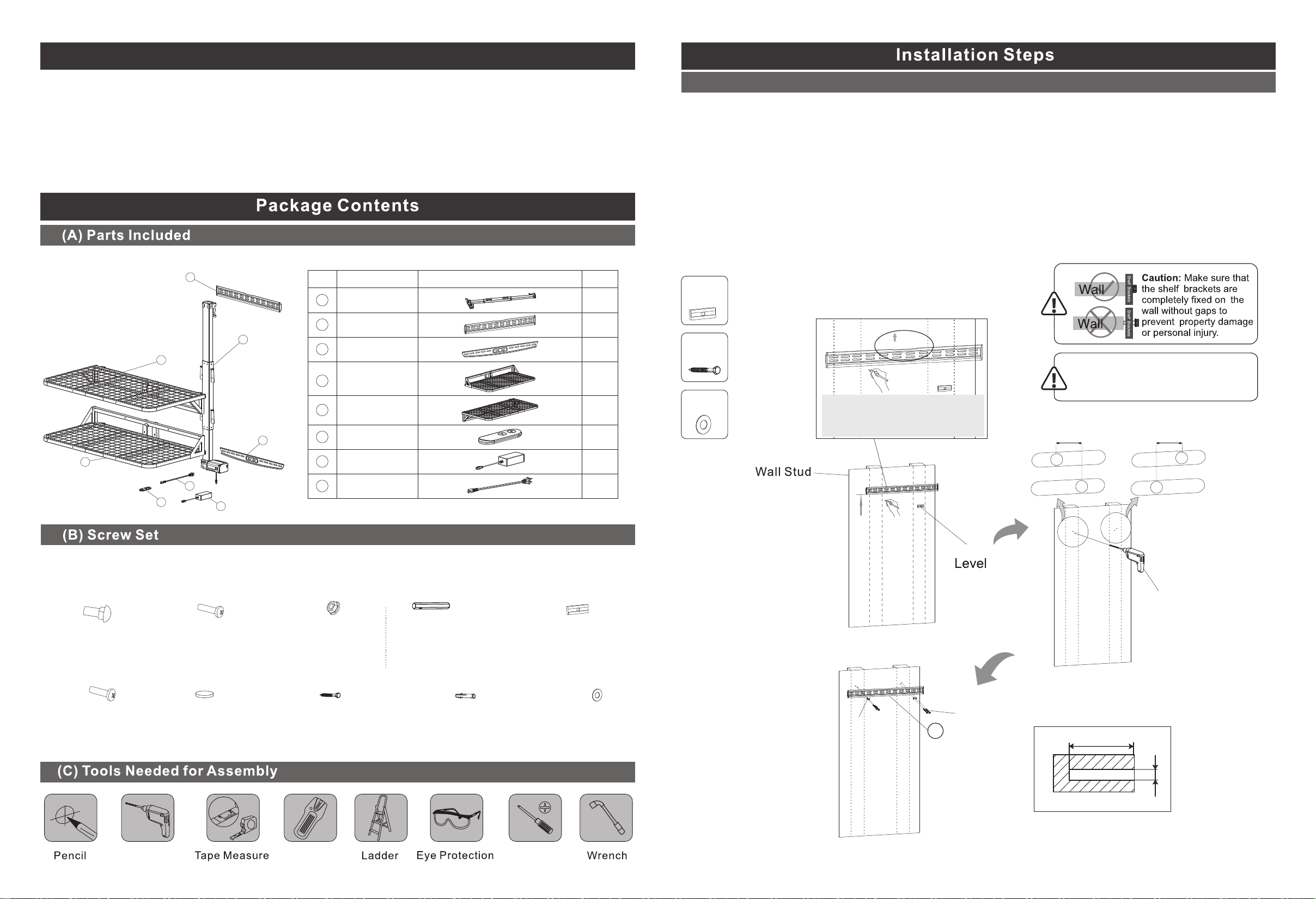
Attention
1. THIS IS A DO IT YOURSELF (DIY) PROJECT. DO NOT ATTEM PT THIS IN STALLATION WITHOUT
A BASIC UNDERSTANDI NG OF THE CONTENTS IN THESE ASSEM BLY INSTRUCTIONS.
2. THERE AR E TWO INSTALLATION OPTI ONS FOR WA LL STUDS OR SOLID CONCRETE WALL.
PLEASE CHOOSE THE P ROPER WAY ACC ORDING TO TH E TYPE OF THE WALL.
3. DO NOT US E TO LIFT PEOP LE OR ANIMAL S.
4. NEVER OPERATE WHI LE HAND(S ) ARE NEAR MOVING PARTS .
5. DO NOT STAND UNDER LIFT.
2
1
5
3
NO.
1
2
3
4
5
6
Accessory
Upright S upport
Top Wal lPlate
Bottom Wall Pl ate
The lower S helf
The upper S helf
Remote Co ntrol
Parts
Qty
1
1
1
1
1
1
Step 1 - Option A: Attach the top wall plate to wood studs
1. Use the stud finder to locate the wall studs.
2. Place the magnetic level to the top wall plate (2). Marking the mounting holes using the wall
plate. Pay attention to the holes placement and the distance between two holes, as shown on
the figure.
3. Drill a 2.8'' (70mm) deep 0.2'' (5mm) diameter pilot hole using 3/16'' drill bit at the center of
each marked point.
4. Attach the top wall plate to the wall studs using washers (B3) and lag bolts (B1). Tighten with
socket wrench.
D
x1
B1
B3
x4
x4
Place the wall plate as
shown on the figure,
keeping the slot upside.
UP
Suggested Installation Height
90'' - 96" (2300mm - 2400mm)
from the floor.
0.39" (10 mm) 0.39" (10 mm)
4
8
6
7
Power Adapter
7
Connect ing Cable
8
1
1
Note: The drawings here are for reference only, it may not accurately depict the real appearance.
Please contact customer service if there are missing parts or screws.
A B C D
M8x22mm
Bolts
(2 pcs)
E
M6x25mm
Bolts
(4pcs)
M5x25mm
Bolts
(1 pc)
F
Button Cell
(1 pc)
Anti-loose Nut
(2 pcs)
B1
St8x70mm
Lag Bolts
(6 pcs)
M8
Socket Wrench
(1 pc)
B2
10x60mm
Plastic Expansion Bolts
(6 pcs)
Magnetic level
(1 pc)
B3
Washers
(6 pcs)
90'' - 96" (2300mm - 2400mm)
D
Pistol-Grip Drill
B3
B1
2
2.8'' (70mm)
Φ3/16'' (5mm)
Pistol-Grip Drill
01 02
/Hammer Drill
Stud Finder
Screw Driver
Page 3
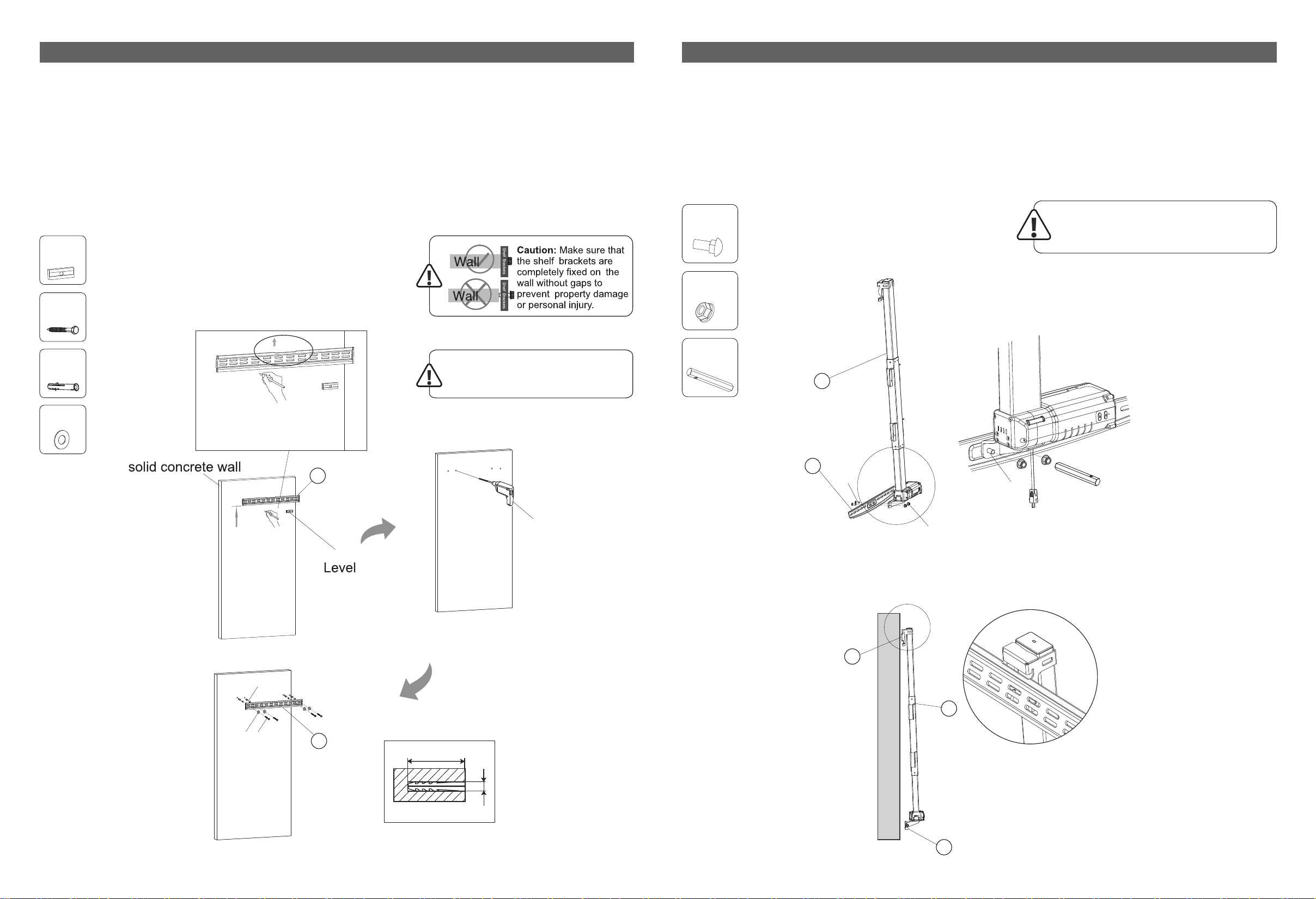
Step 1 - Option B: Attach the top wall plate to solid concrete wall
Step 2: Assemble the upright support
1. Place the magnetic level to the top wall plate (2). Marking the mounting holes
using the wall plate.
2. Drill a 2.8'' (70mm) deep 0.39'' (10mm) diameter pilot hole using 3/8'' drill bit at
the center of each marked point.
3. Attach the top wall plate to solid concrete wall using plastic expansion bolts (B2),
washers (B3) and lag bolts (B1). Tighten with socket wrench.
D
x1
B1
x4
UP
B2
B3
x4
x4
Place the wall plate as
shown on the figure,
keeping the slot upside.
90'' - 96" (2300mm - 2400mm)
2
Suggested Installation Height
90'' - 96" (2300mm - 2400mm)
from the floor.
1. Attach the bottom wall plate (3) to the upright support beam (1) using bolts (A) and nuts (C).
2. Attach the upright support beam (1) to the top wall plate (2).
A
C
C
x2
x2
x1
1
Place the upright support flat on the
ground when attach the bottom wall
plate, for safety consideration.
C
3
A
A
B3
B1
B2
Hammer Drill
D
2
2
2.8'' (70mm)
Φ3/8'' (10mm)
C
1
3
03 04
Page 4
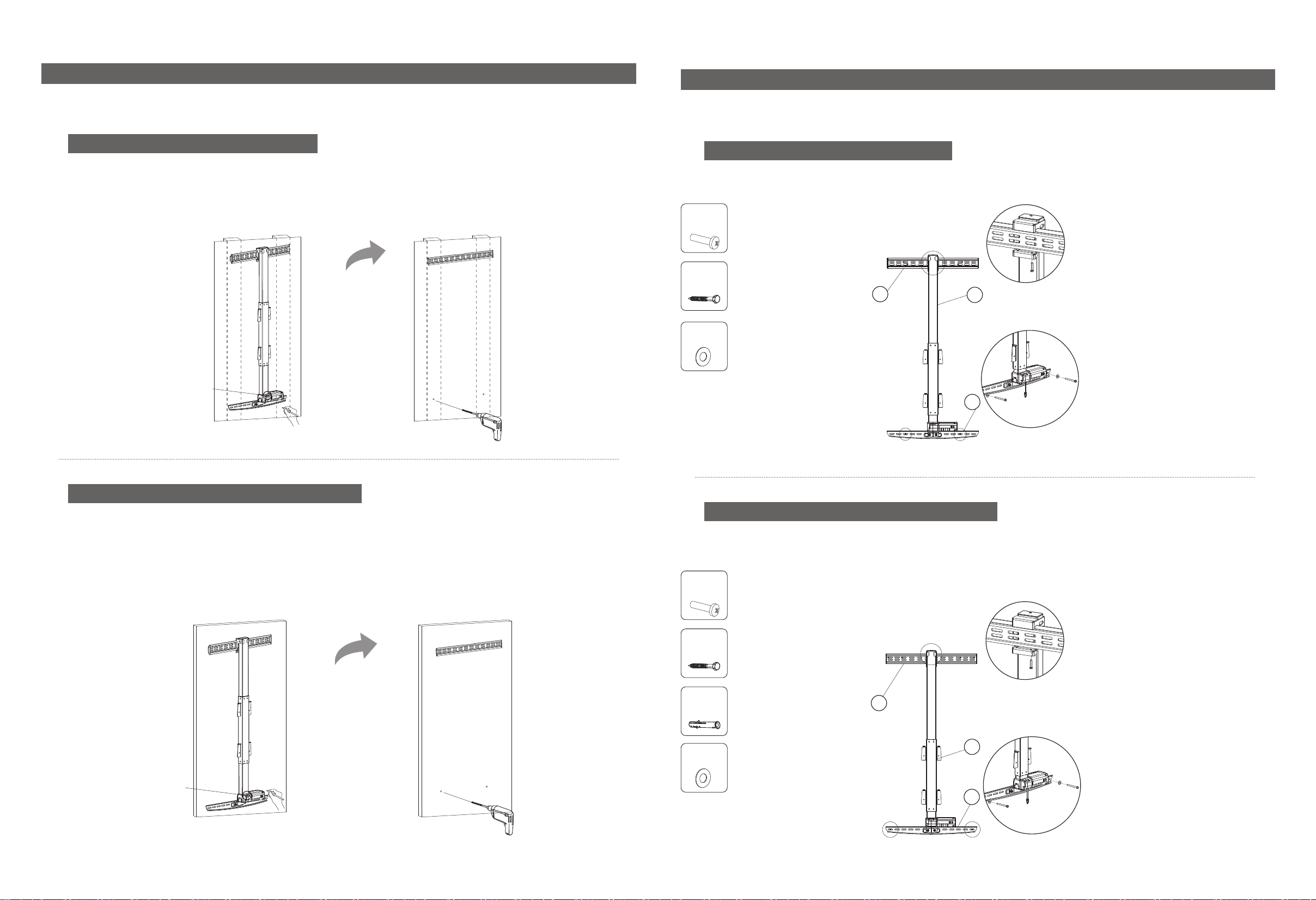
Step 3: Mark the holes for the bottom wall plate assembly
Step 4: Attach and fix the upright support
Attach the upright support beam (1) to the top wall plate (2) and fix and tighten with bolt (B).
Step 3 - Option A: Wood Stud Installation
1. Mark the holes according to the placement of the bottom wall plate.
2. Drill a 2.8'' (70mm) deep 0.2'' (5mm) diameter pilot hole using 3/16'' drill bit at the center of
each marked point. (Hole size refers to Step 1 - Option A.)
Level
Pistol-Grip Drill
Step 4 - Option A: Wood Stud Installation
Fix the bottom wall plate (3) using washers (B3) and lag bolts (B1).
B
x1
B1
x4
2
1
B
B3
x4
3
B1
B3
Step 3 - Option B: Solid Concrete Wall Installation
1. Mark the holes according to the placement of the bottom wall plate.
2. Drill a 2.8'' (70mm) deep 0.39'' (10mm) diameter pilot hole using 3/8'' drill bit at the center of
each marked point. (Hole size refers to Step 1 - Option B.)
Level
Hammer Drill
Step 4 - Option B: Solid Concrete Wall Installation
Fix the bottom wall plate (3) using plastic expansion bolts (B2), washers (B1) and lag bolts (B2).
B
x1
B1
x4
B
B2
x4
B3
x4
2
1
B3
3
B1
05 06
Page 5
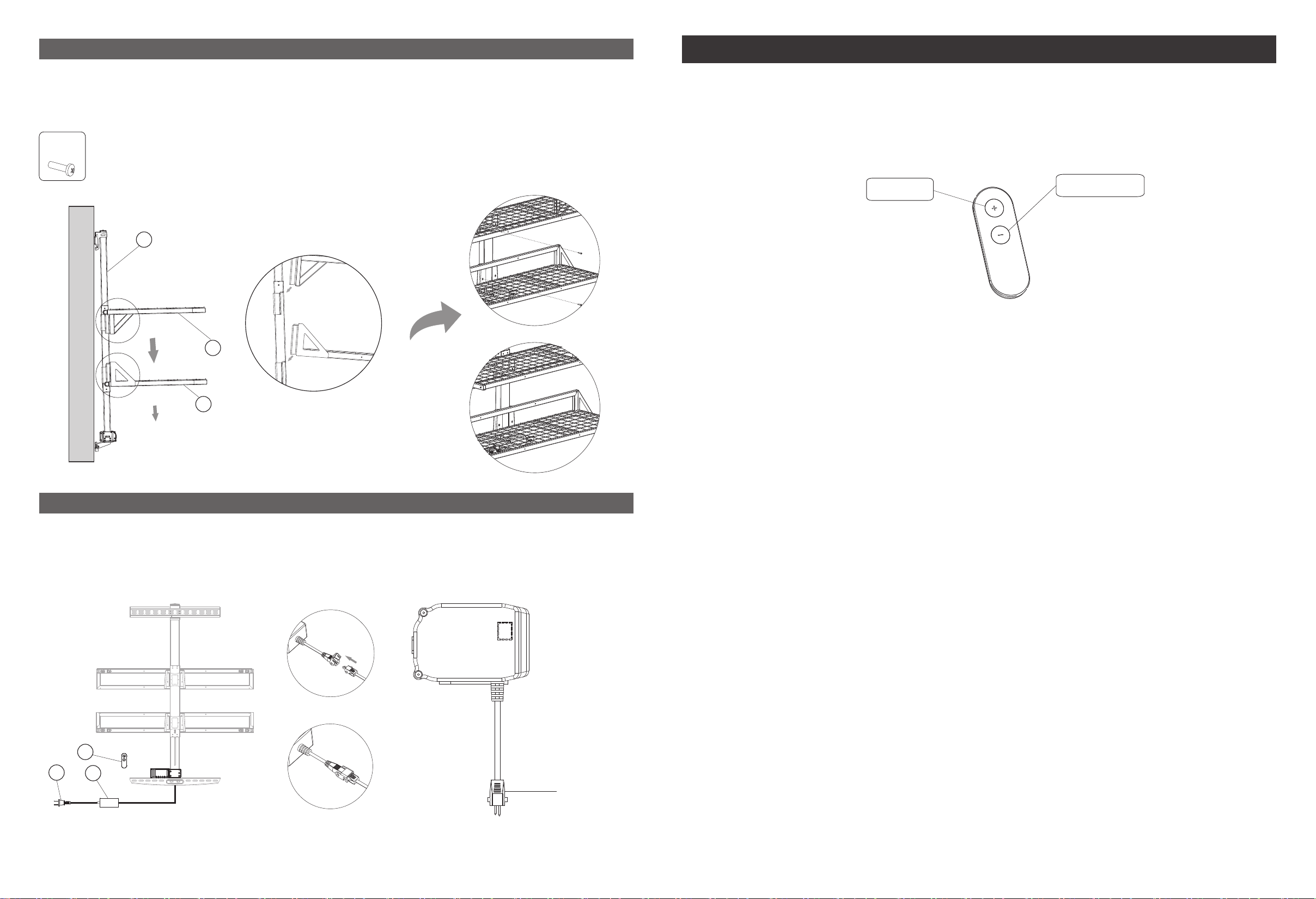
Step 5: Assemble the shelves
Operation Guide
As shown on the figure, insert the upper and lower shelves (4 and 5) inclined to the upright
support beam and fix them with bolts (E).
E
x4
1
4
5
E
Press the UP button or DOWN button to lift or lower the height of the wall shelves.
UP button
(1)Press once the UP button, the wall shelves will go up until to the highest point. Press any button
to stop at any position.
(2)Press once the DOWN button, the wall shelves will go down until to the lowest point. Press any
button to stop at any postion.
DOWN button
Step 6: Connect the power adapter
Connect the remote control (6), and power adapter (7) to the motor with connecting cable (8).
6
8
7
Connecting Cable
(3) There are two backup UP and DOWN button on the motor base.
(4) Troubleshooting:
(a) If the indicator light flickers 1 time per second, the buzzer prompts 1 time per second, it is
reminding that the device exceeds the continuous running time. Rest for 18 minutes and use it
again.
(b) If the indicator light flickers 2 times per second, the buzzer prompts 2 times per second, it is a
reminder to reset the device. Press and hold the DOWN button until the shelves move to the
lowest point, then move back and stop. Rest finished.
(c) If the DOWN button doesn't work. Please check the cable connection and cut off the power for
at least 10 seconds. Then reset the device as instructed in (b).
(5) Optional function: if a garage has 2 or more flexispot motorized wall shelves, please pair the
wall shelves with the remote controller following the steps:
(a) Simultaneously press and hold the UP and DOWN button on the motor base to enter the pairing
mode, and the indicator light will flicker. (Press any key to exit the pairing mode);
(b) Keep the remote control aligned to the panel of the motor base and simultaneously press and
hold the UP and DOWN button of the remote until the indicator light stop flickering. The remote can
only control one device at one time.
(c) If the remote doesn't work after changing the battery, pair the device as instructed in (a) and (b).
07 08
Page 6
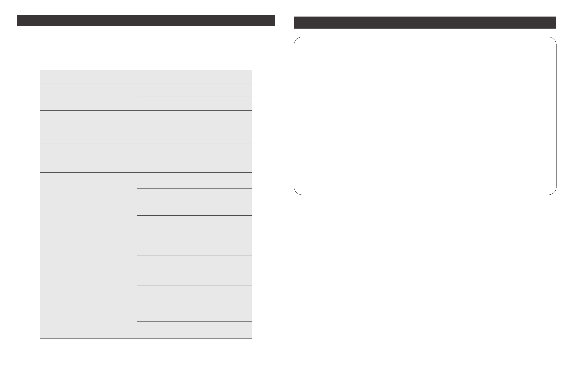
Troubleshooting
This list is used for checking and solving common faults and errors. Please contact the
manufacturer if problem you encounter is not on the list below. All these faults or errors can only
be investigated and corrected by manufacturer or specially trained personnel.
Problem
The DOWN button doesn't work when
the power on.
The UP and DOWN button both don't
work when the power on.
Speed of lifting is slow
Motor does not work properly
Can lift but cannot lower down
Solution
1. Check the cable connection.
2. Contact the distributor or the manufacturer.
1. Check the cable connection.
.
2 Check if the remote is out of battery, or if the
remote is aligned with the motor base.
2. Contact the distributor or the manufacturer.
Reset the device.
1. Contact the distributor or the manufacturer.
1. Check if the load weighs more than 1 65 lbs.
2. Contact the distributor or the manufact urer.
Attention
·Power supply: AC100V - 240V, frequency 50/60HZ;
·Working environment: 32° - 1 04°F (0 - 4 0°C);
·Before cleaning, you have to unplug the power supply cable. Clean with a slightly damp cloth to
wipe away the surface dust. Keep all electrical components away from liquids. Do not damage the
connection line and keep the plug in a safe position.
·Inside the control box, there are electronic components, metal parts, plastic parts, wires and so on.
They should be disposed in accordance with the local laws and regulations. They cannot be disposed
as household waste.
·Before using the product, please make sure the product has been installed correctly.
·Before starting use of the product, please read the instructions to fully understand all the product's
functions and settings.
·Keep children away from the electric height adjustable wall shelves.
Manufacturer is not responsible of any damages that result from children's unpredictable behaviour.
·Slight noise caused by the multi wedge belt or brake system will not impact the use of this product.
·Do not use corrosive or abrasive materials to clean this product and please dispose of cleaning
solutions in an environmentally friendly manner.
·Understand the risks associated with using this product. Children or those with cognitive impairment
should not use this product without supervision.
·Make sure that your operating environment does not have any danger sources, such as not throwing
your tools anywhere. And always Carefully deal with packaging materials to avoid all possible hazards
such as children playing with plastic bags that may cause a choking hazard.
·If necessary, retain the original package for future transportation.
Worksurface downward sliding
Device goes to reset procedure
frequently.
The device exceeds the continuo us
working time. Duty cycle: Max2min (
ON/18minOFF)
Cannot lift or lower down to the
allowable height range
1. Check if the load weighs more than 1 65 lbs.
2. Contact the distributor or the manufact urer.
1. Check if the load weighs more than 1 65 lbs.
Press and hold the button until the shelves
move to the lowest point.
2. Contact the distributor or the manufacturer.
1. Rest for 18 minutes and use it again.
2. Contact the distributor or the manufacturer.
1. Press and hold the DOWN button until the
shelves move to the lowest point, then
move back and stop. Rest finished.
2. Contact the distributor or the manufact urer.
09 10
 Loading...