

Page 1
User Manual
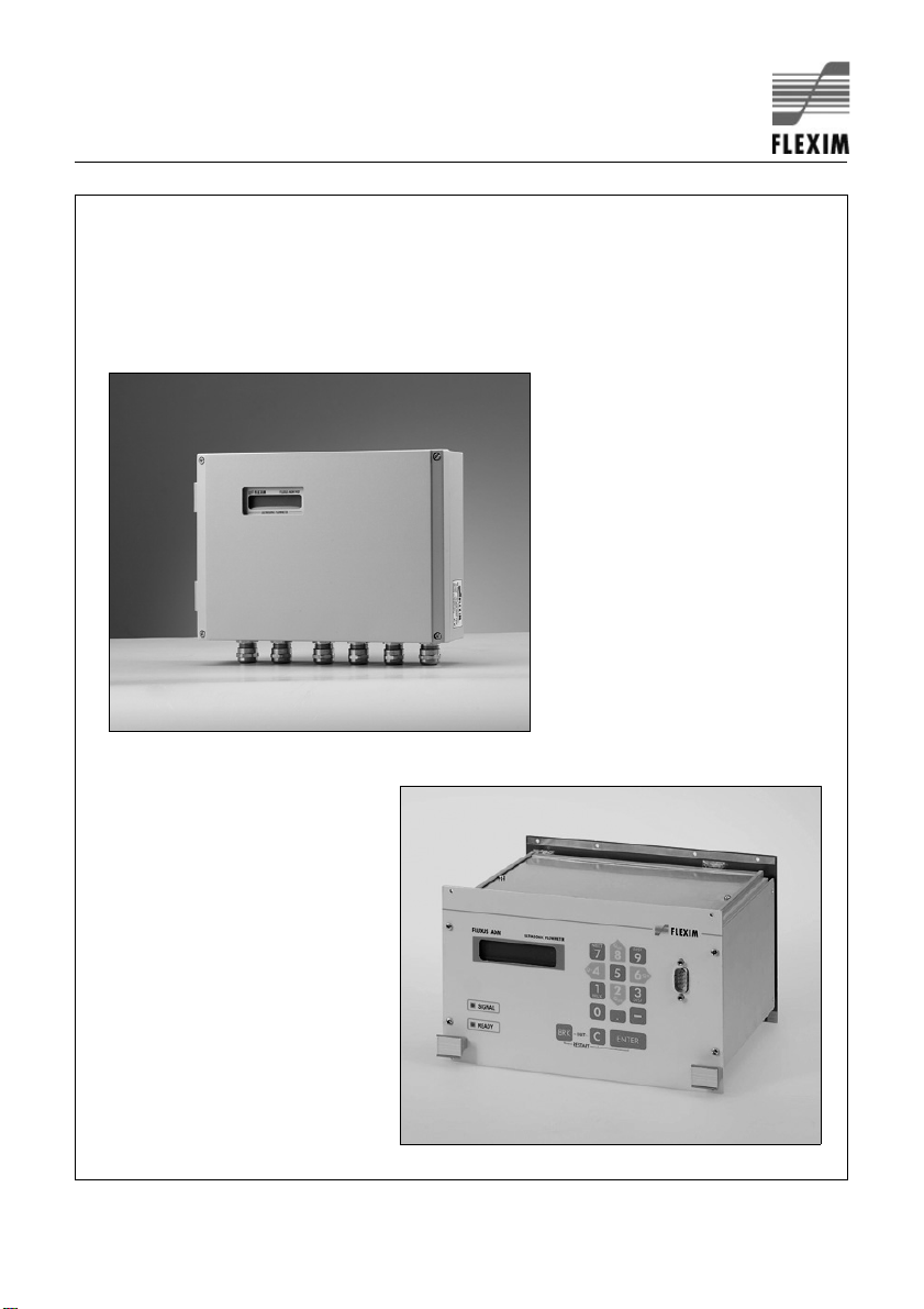
Ultrasonic Flowmeter for Gas
FLUXUS G709
FLUXUS G704
FLUXUS G704 A2
UMG70XV3-4EN
Firmware V5.xx
Page 2

remark:
MS-DOS, Excel, Windows are registered trademarks of Microsoft Corporation.
FLUXUS is a registered trademark of FLEXIM GmbH.
FLEXIM GmbH
Wolfener Strasse 36
12681 Berlin
Germany
Tel.: +49 (30) 936 67 660
Fax: +49 (30) 936 67 680
E-mail: [email protected]
www.flexim.com
User Manual for
FLUXUS G70X
UMG70XV3-4EN 12.01.2009
Firmware V5.xx
Copyright (©) FLEXIM GmbH 2009
Subject to change without notification.
Page 3
Die Sprache, in der die Anzeigen auf dem FLUXUS erscheinen, kann eingestellt werden (siehe Abschnitt 9.4).
FLUXUS can be operated in the language of your choice (see section 9.4).
Il est possible de sélectionner la langue utilisée par FLUXUS à l'écran (voir
section 9.4).
FLUXUS puede ser manejado en el idioma de su elección (ver sección 9.4).
Page 4

Page 5

Table of Contents
1Introduction..........................................................................................................9
1.1 Regarding this Manual...........................................................................................9
1.2 Safety Precautions.................................................................................................9
1.3 Warranty ..............................................................................................................10
2 Safety Instructions according to Directive 94/9/EC........................................11
2.1 Safety Instructions for the Use of Flowmeter FLUXUS G704 A2 in
Explosive Atmosphere .........................................................................................11
2.2 Use of the Junction Box JB01S#E3# in Explosive Atmosphere .........................13
2.3 Use of Ultrasonic Transducers in Explosive Atmosphere (Zone 1/Zone 21) ......15
3Handling.............................................................................................................24
3.1 First Inspection ....................................................................................................24
3.2 General Precautions ............................................................................................24
3.3 Cleaning...............................................................................................................24
4 Flowmeter...........................................................................................................25
4.1 Measuring Principle .............................................................................................25
4.2 Description of the Flowmeter ...............................................................................26
4.3 Keyboard .............................................................................................................28
5 Selection of the Measuring Point .....................................................................30
5.1 Acoustic Penetration............................................................................................30
5.2 Undisturbed Flow Profile......................................................................................31
5.3 Influence of Noise ................................................................................................34
5.4 Selection of the Measuring Point Taking into Account Flow Profile and
Influence of Noise ................................................................................................36
6 Installation of FLUXUS G704............................................................................38
6.1 Location ...............................................................................................................38
6.2 Wall Installation....................................................................................................38
6.3 Pipe Installation ...................................................................................................39
6.4 Connection of the Transducers - Connection System TS....................................40
6.5 Connection of the Transducers - Connection System AS ...................................50
6.6 Connection of the Power Supply .........................................................................51
6.7 Connection of the Outputs ...................................................................................52
6.8 Connection of the Inputs......................................................................................54
UMG70XV3-4EN 12.01.2009
Page 6

6.9 Connection of the Serial Interface....................................................................... 56
6.10 Connection of the Sensor Module (SENSPROM)............................................... 56
7 Installation of FLUXUS G709............................................................................ 58
7.1 Location...............................................................................................................58
7.2 Connection of the Transducers - Connection System TS ...................................58
7.3 Connection of the Transducers - Connection System AS ................................... 66
7.4 Connection of the Power Supply......................................................................... 67
7.5 Connection of the Outputs ..................................................................................68
7.6 Connection of the Inputs ..................................................................................... 70
7.7 Connection of the Serial Interface....................................................................... 72
7.8 Connection of the Sensor Module (SENSPROM)............................................... 73
8 Installation of the Temperature Probe (Option)..............................................74
8.1 Fixing of the Temperature Probe ........................................................................ 74
8.2 Connection of the Temperature Probe................................................................75
9 Start-up .............................................................................................................. 76
9.1 Switching on........................................................................................................76
9.2 Displays...............................................................................................................76
9.3 HotCodes ............................................................................................................ 78
9.4 Language Selection ............................................................................................79
9.5 Operation State Indication (G709) ......................................................................79
9.6 Interruption of the Power Supply......................................................................... 79
10 Basic Measurement .......................................................................................... 80
10.1 Input of the Pipe Parameters ..............................................................................80
10.2 Input of the Medium Parameters......................................................................... 82
10.3 Other Parameters................................................................................................ 84
10.4 Selection of the Channels ................................................................................... 85
10.5 Define Number of Sound Paths .......................................................................... 86
10.6 Installation of the Damping Mats......................................................................... 87
10.7 Mounting and Positioning the Transducers .........................................................91
10.8 Start of Measurement.......................................................................................... 98
10.9 Detection of Flow Direction .................................................................................99
10.10 Stopping the Measurement .................................................................................99
UMG70XV3-4EN 12.01.2009
Page 7

11 Displaying the Measured Values ...................................................................100
11.1 Selection of the Physical Quantity and of the Unit of Measurement ................. 100
11.2 Toggling between the Channels........................................................................ 101
11.3 Adjustment of the Display ................................................................................. 102
11.4 Status Line ........................................................................................................103
11.5 Transducer Distance .........................................................................................104
12 Advanced Measuring Functions....................................................................105
12.1 Damping Factor................................................................................................. 105
12.2 Totalizers...........................................................................................................105
12.3 Upper Limit of the Flow Velocity........................................................................ 108
12.4 Cut-off Flow.......................................................................................................109
12.5 Uncorrected Flow Velocity ................................................................................110
12.6 Measurement of Transient Processes (FastFood mode) .................................. 111
12.7 Calculation Channels ........................................................................................112
12.8 Change of Limit for the Inner Pipe Diameter..................................................... 115
12.9 Program Code...................................................................................................115
13 Storing and Output of Measured Values....................................................... 117
13.1 Data Memory..................................................................................................... 118
13.2 Output of the Measured Values ........................................................................119
13.3 Delete the Measured Values............................................................................. 126
13.4 Settings for the Data Memory ...........................................................................126
13.5 Available Data Memory .....................................................................................128
14 Libraries........................................................................................................... 129
14.1 Partitioning of the Coefficient Memory .............................................................. 129
14.2 Input of Material/Medium Properties without the Extended Library................... 131
14.3 Extended Library ...............................................................................................132
14.4 Deleting a User Defined Material/Medium......................................................... 136
14.5 Arrangement of the Material/Medium Scroll List ............................................... 136
15 Settings............................................................................................................ 139
15.1 Time and Date................................................................................................... 139
15.2 Dialogs and Menus ...........................................................................................139
15.3 Measurement Settings ...................................................................................... 142
15.4 Settings of the Standard Conditions for the Gas Measurement ........................ 144
15.5 Setting the Contrast ..........................................................................................144
15.6 Instrument Information ......................................................................................145
UMG70XV3-4EN 12.01.2009
Page 8

16 SuperUser-Mode .............................................................................................146
16.1 Activating/Deactivating...................................................................................... 146
16.2 Transducer Parameters ....................................................................................146
16.3 Malfunctions in SuperUser Mode ...................................................................... 147
17 Inputs ............................................................................................................... 148
17.1 Linking the Temperature Inputs to the Measuring Channels............................. 148
17.2 Selection of the Temperature Probe (FLUXUS G704)......................................149
17.3 Linking Other Inputs to the Measuring Channels .............................................. 149
17.4 Activation of the Inputs......................................................................................150
17.5 Temperature Correction .................................................................................... 151
18 Outputs ............................................................................................................ 152
18.1 Installation of an Output .................................................................................... 152
18.2 Error Value Delay.............................................................................................. 157
18.3 Activation of an Analog Output..........................................................................157
18.4 Activation of a Pulse Output.............................................................................. 158
18.5 Activation of an Alarm Output ........................................................................... 159
18.6 Behavior of the Alarm Outputs .......................................................................... 162
18.7 Deactivating the Outputs................................................................................... 164
19 Troubleshooting..............................................................................................165
19.1 Problems with the Measurement....................................................................... 166
19.2 Correct Selection of the Measuring Point.......................................................... 167
19.3 Maximum Acoustic Contact...............................................................................168
19.4 Application Specific Problems...........................................................................168
19.5 High Measuring Deviations ............................................................................... 168
19.6 Problems with the Totalizers ............................................................................. 169
A Technical Data ................................................................................................170
Flowmeter ........................................................................................................ 170
Transducers .....................................................................................................175
Junction Box .................................................................................................... 201
B Menu Structure................................................................................................208
C Reference.........................................................................................................230
D Certificates....................................................................................................... 235
UMG70XV3-4EN 12.01.2009
Page 9

1 Introduction
1 Introduction
1.1 Regarding this Manual
This manual has been written for the personnel operating the ultrasonic flowmeter FLUXUS. It contains important information about the instrument, how to handle it correctly,
how to avoid damages. Always keep this manual at hand.
Get acquainted with the safety rules and the handling precautions. Make sure you have
read and understood this manual before using the instrument.
All reasonable effort has been made to ensure the correctness of the content of this manual. If you however find some erroneous information, please inform us. We will be grateful for any suggestions and comments regarding the concept and your experience working with the instrument.
This will ensure that we can further develop our products for the benefit of our customers
and in the interest of technological progress. If you have any suggestions about improving the documentation and particularly this User Manual, please let us know so that we
can consider your comments for future reprints.
The content of this manual is subject to changes without prior notice. All rights reserved.
No part of this manual may be reproduced in any form without FLEXIM's written permission.
1.2 Safety Precautions
You will find in this manual the following safety information:
Note! The notes contain important information which help you use the flow-
meter optimally.
Attention! This text contains important instructions which should be observed to
avoid damage or destruction of the flowmeter. Proceed with attention!
This texts denotes instructions according to directive 94/9/EC.
Observe these safety precautions!
UMG70XV3-4EN 12.01.2009 9
Page 10

1 Introduction
1.3 Warranty
The FLUXUS flowmeter is guaranteed for the term and to the conditions specified in the
sales contract provided the equipment has been used for the purpose for which it has
been designed and operated according to the instructions given in this User Manual.
Misuse of the FLUXUS will immediately revoke any warranty given or implied.
This includes:
• replacement of a component of FLUXUS by a component that was not authorized by
FLEXIM
• unsuitable or insufficient maintenance
• repair of FLUXUS by unauthorized personnel
FLEXIM assumes no responsibility for injury to the customer or third persons proximately
caused by the material owing to defects in the product which were not predictable or for
any indirect damages.
FLUXUS is a very reliable instrument. It is manufactured under strict quality control, using modern production techniques. If installed as recommended in an appropriate location, used cautiously and taken care of conscientiously, no troubles should appear.
If any problem appears which can not be solved with the help of this manual (see chapter
19), contact our sales office giving a precise description of the problem. Specify the type,
serial number and firmware version of the flowmeter.
10 UMG70XV3-4EN 12.01.2009
Page 11

2 Safety Instructions according to Directive 94/9/EC
2 Safety Instructions according to Directive 94/9/EC
2.1 Safety Instructions for the Use of Flowmeter FLUXUS
G704 A2 in Explosive Atmosphere
The conformance with all relevant standards will be guaranteed only
if the flowmeter is connected only with the transducers specified by
FLEXIM for the corresponding application.
Observe the specified operating and explosion protection temperatures (see Technical Data on the following pages).
Do not open the housing in explosive atmosphere if the flowmeter is
connected with the power supply. After the power supply was disconnected, wait 10 minutes before opening the housing.
The equipotential bonding terminal has to be u s ed for the connection
of the protective earth.
Cable gland openings not used have to be properly closed with appropriate plugs. They must be removable only with tools.
The flowmeter is safe in explosive atmosphere only when all connections have been made correctly according to the instructions in the
user manual.
Make sure that all cables fit firmly and tightly in the cable glands, the
cable glands are firmly tightened and the housing has been tightly
screwed.
UMG70XV3-4EN 12.01.2009 11
Page 12
2 Safety Instructions according to Directive 94/9/EC
Technical Data
For further technical data see annex A, section Technical Data.
FLUXUS G704 A2
manufacturer FLEXIM GmbH
marking
type of protection gas: not sparking nA
power supply 100…240 V AC or
degree of protection IP 66 according to EN 60529
explosion protection temperature
according to ATEX
Wolfener Str. 36
12681 Berlin
II3G Ex nA II T4 Ta -20…+60 °C
II3D Ex tD A22 IP66 T100°C
dust: protection by enclosure tD
20…32 V DC
-20…+60 °C
12 UMG70XV3-4EN 12.01.2009
Page 13
2 Safety Instructions according to Directive 94/9/EC
2.2 Use of the Junction Box JB01S#E3# in Explosive Atmosphere
Observe the specified operating and explosion protection temperatures of the junction box (see Technical Data on the following page).
Never open the housing in explosive atmosphere if the junction box is
connected to a flowmeter that is connected to a power supply.
Never replace a component of the junction box by parts other than
those supplied by FLEXIM.
The junction box is safe in explosive atmosphere only when all connections have been made correctly according to the instructions in
the user manual.
If other cable glands are used than those supplied by FLEXIM, they
have to be approved for the application area and the cable diameters
have to be observed.
Make sure that all cables fit firmly and tightly in the cable glands, the
cable glands are firmly tightened and the housing has been tightly
screwed.
The equipotential bonding terminal has to be used for the connection
of the protective earth.
Cable gland openings not used have to be properly closed with
checked and approved plugs. They must be removable only with
tools.
The conductor cross-sections of the leads in the Ex e junction box
have to be in the range 0.2...2.5 mm
2
. For multiple wire connection to
one terminal, max. 2 wires of same cross-section and type must be
connected. In this case, the conductor cross-sections have to be in
the range 0.2...0.75 mm
UMG70XV3-4EN 12.01.2009 13
2
.
Page 14
2 Safety Instructions according to Directive 94/9/EC
The cover of the junction box has to be closed firmly.
Technical Data
For further information see annex A, section Technical Data.
Junction Box JB01S#E3#
FLEXIM GmbH
manufacturer
marking
certification
type of protection junction box: increased safety
degree of protection IP 67 according to EN 60529
explosion protection temperature
according to ATEX
Wolfener Str. 36
12681 Berlin
0044;
Ex e mb II (T6)...T4 T
Ex tD A21 IP67 T 100 °C
IBExU06ATEX1161
IECEx IBE08.0006
decoupled network: encapsulation
dust: protection by enclosure tD
temperature class T4: -40…+80 °C
temperature class T5: -40…+80 °C
temperature class T6: -40…+70 °C
II2G
II2D
-40...+(70)80 °C
a
14 UMG70XV3-4EN 12.01.2009
Page 15

2 Safety Instructions according to Directive 94/9/EC
2.3 Use of Ultrasonic Transducers in Explosive Atmosphere
(Zone 1/Zone 21)
Observe the specified operating and explosion protection temperatures of the transducers. For the explosion protection temperatures
see table on the following page.
The transducers
**M1N31, **P1N31, **Q1N31, **K1N31, **K1N41,
**G1N31, **G1N41, **K1N33, **K1N43, **G1N33,
**G1N43, **H1N33, **H1N43, **M2N41, **P2N41,
**M1N43, **P1N43, **M2E45, **P2E45, **K1N71,
**K1N81, **G1N71, **G1N81, **K1N73, **K1N83,
**G1N73, **G1N83, **H1N73, **H1N83, **M2N81,
**P2N81, **M1N83, **P1N83, **K1LI1, **G1LI1
**M2LI1, **P2LI1, **M2E85, **P2E85, **Q2E85,
**Q2N81, **Q1N83
can be used in explosive atmosphere in zones 1, 2, 21 and 22.
The transducers listed above can be connected to the flowmeter of
the FLUXUS series.
The flowmeter either has to be located outside of the explosive atmosphere or has to be checked and approved separately for explosion
protection.
All cable connections either have to be located outside of the explosive atmosphere or have to be used with equipment checked and approved for explosion protection.
The transducers may be used in explosive atmosphere only under
the following conditions:
• the transducers are fixed to a pipe or to the surface of a vessel
• the contact surface of every transducer is directed towards the surface of the pipe or of the vessel on which it is mounted
If an equipotential bonding of the transducers is necessary, the
ground terminal of the transducer housing has to be used.
UMG70XV3-4EN 12.01.2009 15
Page 16
2 Safety Instructions according to Directive 94/9/EC
The transducers
**K1N41, **G1N41, **K1N43, **G1N43, **H1N43, **M2N41,
**P2N41, **M1N43, **P1N43, **M2E45, **P2E45, **K1N81,
**G1N81, **K1N83, **G1N83, **H1N83, **M2N81, **P2N81,
**M1N83, **P1N83, **K1LI1, **G1LI1, **M2LI1, **P2LI1,
**M2E85, **P2E85, **Q2E85, **Q2N81, **Q1N83
must always be used in the delivered transducer shoe to protect
them against mechanical stress.
If an equipotential bonding of the transducers is necessary, the
ground terminal of the transducer housing and/or of the transducer
shoe has to be used.
The transducers must be connected with the flowmeter only if there is
no risk of an explosive atmosphere or if the flowmeter is not connected with the power supply.
When using the transducers in areas with combustible dust (zone
21), the max. surface temperature TX = T
+ 5 K (TRB - surface
RB
temperature of the pipe or vessel on which the transducer is
mounted).
16 UMG70XV3-4EN 12.01.2009
Page 17

2 Safety Instructions according to Directive 94/9/EC
explosion protection
temperature of transducers
**M1N31, **P1N31, **Q1N31 -20 …+120 °C -20…+120 °C
**M2N41, **P2N41, **K1N41,
**G1N41, **M2N81, **P2N81,
**K1N81, **G1N81, **Q2N81
**K1N31, **G1N31, **K1N71,
**G1N71
**M1N43, **P1N43, **K1N43,
**H1N43, **G1N43, **M1N83,
**P1N83, **K1N83, **G1N83,
**H1N83, **Q1N83
**K1N73, **G1N73, **H1N73,
**K1N33, **H1N33, **G1N33
**K1LI1, **G1LI1,
**M2LI1, **P2LI1
**M2E85, **P2E85, **Q2E85 -45…+225 °C -45…+225 °C
**M2E45, **P2E45 -45…+225 °C -45…+190 °C
surface
temperature
(pipe/vessel)
-55...+180 °C -55...+180 °C
-40...+180 °C -40...+180 °C
-55...+140 °C -55...+140 °C
-40...+140 °C -40...+140 °C
-55...+180 °C -40…+80 °C
ambient
temperature
(at the cable gland)
(at the cable gland)
UMG70XV3-4EN 12.01.2009 17
Page 18

2 Safety Instructions according to Directive 94/9/EC
Technical Data
For further information see annex A, section Technical Data.
Type **M1N31 , ** P 1 N 3 1 , * * Q 1 N 3 1
manufacturer FLEXIM GmbH, Wolfener Str. 36, 12681 Berlin
marking
0044; II2G
EEx m II T6…T4 T
-20…+120 °C
a
certification IBExU98ATEX1012 X
type of protection encapsulation
degree of protection IP 65 according to EN 60529
explosion protection
temperature according
to ATEX
temperature class T4: -20…+120 °C
temperature class T5: -20…+90 °C
temperature class T6: -20…+75 °C
Type **K1N31, **G1N31
manufacture FLEXIM GmbH, Wolfener Str. 36, 12681 Berlin
marking
0044;
II2G Ex q II T6…T3 T
-40…+180 °C
a
II2D Ex tD A21 IP65 TX
certification IBExU04ATEX1011 X
type of protection transducer: powder filling
dust: protection by enclosure tD
degree of protection IP 65 according to EN 60529
explosion protection
temperature according
to ATEX
temperature class T3: -40…+180 °C
temperature class T4: -40…+125 °C
temperature class T5: -40…+90 °C
temperature class T6: -40…+75 °C
18 UMG70XV3-4EN 12.01.2009
Page 19
2 Safety Instructions according to Directive 94/9/EC
Type **K1N41, **G1N41, **M2N41, **P2N41
manufacturer FLEXIM GmbH, Wolfener Str. 36, 12681 Berlin
marking
0044;
II2G Ex q II T6…T3 T
-55…+180 °C
a
II2D Ex tD A21 IP65 TX
certification IBExU04ATEX1011 X
type of protection transducer: powder filling
dust: protection by enclosure tD
degree of protection IP 65 according to EN 60529
explosion protection
temperature according
to ATEX
temperature class T3: -55…+180 °C
temperature class T4: -55…+125 °C
temperature class T5: -55…+90 °C
temperature class T6: -55…+75 °C
Type **K1N33, **G1N33, **H1N33
manufacturer FLEXIM GmbH, Wolfener Str. 36, 12681 Berlin
marking
0044;
II2G Ex q II T6…T3 T
-40…+140 °C
a
II2D Ex tD A21 IP65 TX
certification IBExU04ATEX1011 X
type of protection transducer: powder filling
dust: protection by enclosure tD
degree of protection IP 65 according to EN 60529
explosion protection
temperature according
to ATEX
temperature class T3: -40…+140 °C
temperature class T4: -40…+125 °C
temperature class T5: -40…+90 °C
temperature class T6: -40…+75 °C
UMG70XV3-4EN 12.01.2009 19
Page 20
2 Safety Instructions according to Directive 94/9/EC
Type **K1N43, **G1N43, **H1N43, **M1N43, **P1N43
manufacturer FLEXIM GmbH, Wolfener Str. 36, 12681 Berlin
marking
0044;
II2G Ex q II T6…T3 T
-55…+140 °C
a
II2D Ex tD A21 IP65 TX
certification IBExU04ATEX1011 X
type of protection transducer: powder filling
dust: protection by enclosure tD
degree of protection IP 65 according to EN 60529
explosion protection
temperature according
to ATEX
temperature class T3: -55…+140 °C
temperature class T4: -55…+125 °C
temperature class T5: -55…+90 °C
temperature class T6: -55…+75 °C
Type **M2E45, **P2E45
manufacturer FLEXIM GmbH, Wolfener Str. 36, 12681 Berlin
marking
0044;
II2G Ex q II T6…T2 T
-45…+225 °C
a
II2D Ex tD A21 IP65 TX
certification IBExU04ATEX1011 X
type of protection transducer: powder filling
dust: protection by enclosure tD
degree of protection IP 65 according to EN 60529
explosion protection
temperature according
to ATEX
temperature class T2: -45…+225 °C
temperature class T3: -45…+190 °C
temperature class T4: -45…+125 °C
temperature class T5: -45…+90 °C
temperature class T6: -45…+75 °C
The service temperature at the cable entry must not
exceed the permissible operating temperature of 190 °C.
20 UMG70XV3-4EN 12.01.2009
Page 21
2 Safety Instructions according to Directive 94/9/EC
Type **K1N71, **G1N71
manufacturer FLEXIM GmbH, Wolfener Str. 36, 12681 Berlin
marking
0044
II2G
II2D
Ex e q II T6...T3
Ex tD A21 IP65 TX
certification IBExU07ATEX1168 X
IECEx IBE08.0007X
type of protection transducer: powder filling
transducer connection: increased safety
dust: protection by enclosure tD
degree of protection IP 65 according to EN 60529
explosion protection
temperature according
to ATEX
temperature class T3: -40…+180 °C
temperature class T4: -40…+125 °C
temperature class T5: -40…+90 °C
temperature class T6: -40…+75 °C
Type **K1N81, **G1N81, **M2N81, **P2N81, **Q2N81
manufacturer FLEXIM GmbH, Wolfener Str. 36, 12681 Berlin
marking
0044;
II2G
II2D
Ex e q II T6...T3
Ex tD A21 IP65 TX
certification IBExU07ATEX1168 X
IECEx IBE08.0007X
type of protection transducer: powder filling
transducer connection: increased safety
dust: protection by enclosure tD
degree of protection IP 65 according to EN 60529
explosion protection
temperature according
to ATEX
temperature class T3: -55…+180 °C
temperature class T4: -55…+125 °C
temperature class T5: -55…+90 °C
temperature class T6: -55…+75 °C
UMG70XV3-4EN 12.01.2009 21
Page 22

2 Safety Instructions according to Directive 94/9/EC
Type **K1N73, **G1N73, **H1N73
manufacturer FLEXIM GmbH, Wolfener Str. 36, 12681 Berlin
marking
0044;
II2G
II2D
Ex e q II T6...T3
Ex tD A21 IP65 TX
certification IBExU07ATEX1168 X
IECEx IBE08.0007X
type of protection transducer: powder filling
transducer connection: increased safety
dust: protection by enclosure tD
degree of protection IP 65 according to EN 60529
explosion protection
temperature according
to ATEX
temperature class T3: -40…+140 °C
temperature class T4: -40…+125 °C
temperature class T5: -40…+90 °C
temperature class T6: -40…+75 °C
Type **K1N83, **G1N83, **H1N83, **M1N83, **P1N83, **Q1N83
manufacturer FLEXIM GmbH, Wolfener Str. 36, 12681 Berlin
marking
0044;
II2G
II2D
Ex e q II T6...T3
Ex tD A21 IP65 TX
certification IBExU07ATEX1168 X
IECEx IBE08.0007X
type of protection transducer: powder filling
transducer connection: increased safety
dust: protection by enclosure tD
degree of protection IP 65 according to EN 60529
explosion protection
temperature according
to ATEX
temperature class T3: -55…+140 °C
temperature class T4: -55…+125 °C
temperature class T5: -55…+90 °C
temperature class T6: -55…+75 °C
22 UMG70XV3-4EN 12.01.2009
Page 23
2 Safety Instructions according to Directive 94/9/EC
Type **K1LI1, **G1LI1, **M2LI1, **P2LI1
manufacturer
FLEXIM GmbH
Wolfener Str. 36
12681 Berlin
marking
0044; II 2G 2D
Ex q II T6...T3
Ex tD A21 IP68 TX
certification
IBExU07ATEX1168 X
IECEx IBE08.0007X
type of protection transducer: powder filling
dust: protection by enclosure tD
degree of protection
explosion protection
temperature according
to ATEX
IP 68 according to EN 60529
temperature class T3: -55…+180 °C
temperature class T4: -55…+125 °C
temperature class T5: -55…+90 °C
temperature class T6: -55…+75 °C
The ultrasonic transducers may be used at the cable
gland only in the temperature range of -40...+80 °C.
Type **M2E85, **P2E85, **Q2E85
manufacturer
FLEXIM GmbH
Wolfener Str. 36
12681 Berlin
marking
0044;
II2G
II3D
Ex e q II T6...T2
Ex tD A22 IP56 TX
certification
IBExU07ATEX1168 X
IECEx IBE08.0007X
type of protection transducer: powder filling
transducer connection: increased safety
dust: protection by enclosure tD
degree of protection
explosion protection
temperature according
to ATEX
IP 56 according to EN 60529
temperature class T2: -45…+225 °C
temperature class T3: -45…+190 °C
temperature class T4: -45…+125 °C
temperature class T5: -45…+90 °C
temperature class T6: -45…+75 °C
UMG70XV3-4EN 12.01.2009 23
Page 24

3 Handling
3 Handling
3.1 First Inspection
The flowmeter has already been tested thoroughly at the factory. At delivery, proceed to
a visual control to make sure that no damage has occurred during transportation.
Check that the specifications of the flowmeter delivered correspond to the specifications
given on the purchase order.
Type and serial number of the flowmeter are given on the data plate. The transducer type
is printed on the transducers.
3.2 General Precautions
Observe the safety instructions in chapter 2.
FLUXUS is a precision measuring instrument and must be handled with care. To obtain
good measurement results and not to damage the instrument, it is important that great
attention is paid to the instructions given in this user manual, and particularly to the following points:
• Protect the flowmeter from excessive shock.
• Do not open the housing without authorization. The degree of protection of the flowmeter FLUXUS G704 A2, G704 is given only if the cover of the housing is tightly screwed.
• Keep the transducers clean. Manipulate the transducer cables cautiously. Avoid excessive cable bend.
• Make sure to work under ambient and operating temperatures (see annex A, section
Technical Data).
• Take the degree of protection into account (see annex A, section Technical Data).
3.3 Cleaning
• Clean the flowmeter with a soft cloth. Do not use detergents.
• Remove traces of acoustic coupling compound from the transducers with a soft paper
tissue.
24 UMG70XV3-4EN 12.01.2009
Page 25
4 Flowmeter
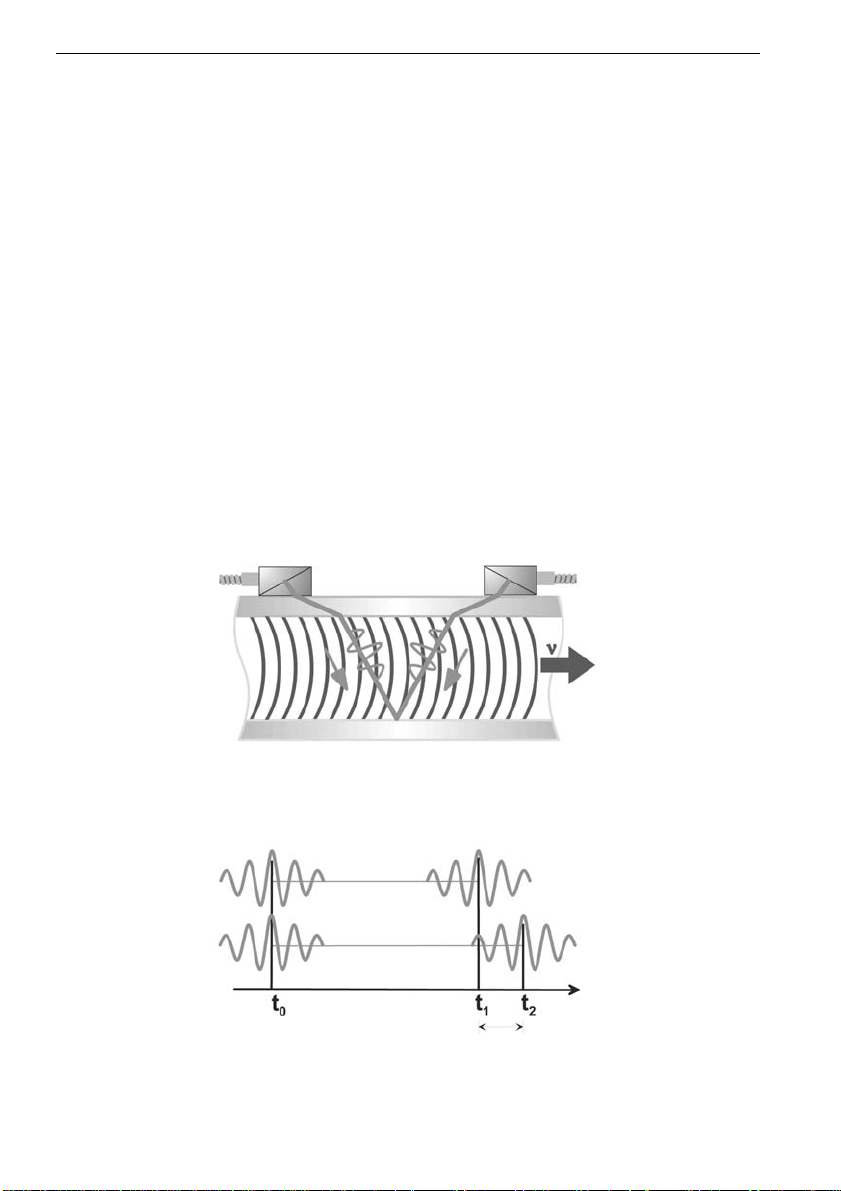
Fig. 4.1: Path of the ultrasonic signal
Fig. 4.2: Transit time difference t
4 Flowmeter
4.1 Measuring Principle
The flow of the medium is measured by ultrasonic signals using the transit time difference method.
Ultrasonic signals are emitted by a transducer installed on one side of a pipe, reflected
on the opposite side and received by a second transducer. The signals are emitted alternatively in and against the flow direction.
As the medium in which the signals propagate is flowing, their transit time in flow direction is shorter than against the flow direction.
The transit time difference t is measured allowing to determine the average flow velocity
on the propagation path of the ultrasonic signals. A flow profile correction is then performed to obtain the area average of the flow velocity, which is proportional to the volume
flow.
The received ultrasonic signals will be tested for usefulness for the measurement and the
plausibility of the measured values will be evaluated. The complete measuring procedure
will be controlled by the integrated microprocessors. Disturbance signals will be eliminated.
UMG70XV3-4EN 12.01.2009 25
Page 26

4 Flowmeter
2x 16-digit LCD
display (backlit)
serial interface
RS232
transducers
outputs
power supply
inputs
keyboard
cover
equipotential bonding terminal
(only FLUXUS G704 A2)
4.2 Description of the Flowmeter
4 Flowmeter
Attention! The degree of protection of the flowmeter is only guaranteed if the cable
glands have been firmly tightened and the cover of the housing has been
tightly screwed.
4.2.1 Design of FLUXUS G704 A2 and FLUXUS G704
The front plate has to be removed to access the command panel.
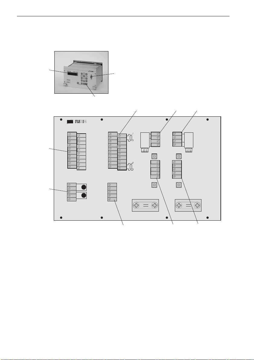
Fig. 4.3: Command panel of FLUXUS G704 A2 and FLUXUS G704
26 UMG70XV3-4EN 12.01.2009
Page 27
4 Flowmeter
T 1 A
T 1 B
P T 1 0 0
T 4 B
T 4 A
P T 1 0 0
B :A :
S A 3
S A 1
S A 2
S A 4
S B 3
S B 1
S B 2
S B 4
A V S
A V
A R S
A G N
A R
B V S
B V
B R S
B G N
B R
A C
2 3 0 V
1 0 0 . . .
D C
V O L T
L O W
4 A +
4 B -
4 2
4 3
4 1
L +
L -
N
L 1
P E
P 4 +
P 5 +
P 2 +
P 3 +
P 1 +
P 6 a
P 7 a
P 7 +
P 5 a
P 6 +
P 4 -
P 5 -
P 2 -
P 3 -
P 1 -
P 6 b
P 7 b
P 7 -
P 5 b
P 6 -
T 2 A
T 2 B
T 1 B
S 1
T 1 A
T 4 A
T 4 B
T 3 B
S 3
T 3 A
T 2 a
T 2 b
T 1 b
S 2
T 1 a
T 4 a
T 4 b
T 3 b
S 4
T 3 a
KL1 KL3 KL5 KL7
KL2 KL4
KL6 KL8
2x 16-digit
LCD display
(backlit)
serial interface RS232
keyboard
outputs
inputs
power supply
transducers of
measuring
channel A
sensor module
measuring
channel A
sensor module
measuring
channel B
transducers of
measuring
channel B
serial interface RS485
4.2.2 Design of FLUXUS G709
The flowmeter is designed as 19 " rack (42 DU, 3 HU).
Fig. 4.4: Command panel and circuit board of FLUXUS G709
UMG70XV3-4EN 12.01.2009 27
Page 28

4 Flowmeter
-
O
+
O
ON
O
OFF
O
-
O
+
O
ON
O
OFF
O
DISP
LF
LIGHT
4.3 Keyboard
4 Flowmeter
The keyboard has three function keys ENTER, BRK and C and ten numerical keys.
Several keys have double functions. They can be used for data entry and for navigation
through scroll lists.
The arrow shaped keys , , and will be used as cursor keys for scrolling
through scroll lists and for input of digits and letters in input mode.
Table 4.1: General functions
ENTER confirmation of selection or of entered value
BRK + C + ENTER RESET: Press these three keys simultaneously to recover from an error. The
reset has the same effect as restarting the flowmeter. Stored data will not be
affected.
BRK interruption of the measurement and selection of the main menu
Note: Be careful not to interrupt a current measurement by inadvertently press-
ing key BRK!
Table 4.2: Navigation
BRK selection of the main menu
scroll to the left or right through a scroll list
scroll upwards and downwards through a scroll list
ENTER Confirmation of the selected menu item
Table 4.3: Input of digits
...
input of the digit shown on the key
sign for the input of negative values
decimal point
C delete values. After the value has been deleted, the previous value will be
displayed.
ENTER confirmation of input
28 UMG70XV3-4EN 12.01.2009
Page 29
4 Flowmeter
-
O
+
O
DISP
DISP
ON
O
OFF
O
%
N E X T
M U X
Table 4.4: Input of text
positioning of the cursor
changes the currently selected character to an "A"
changes the currently selected character to a "Z"
changes between small and capital letters
selection of the precedent/next ASCII character
deletes the character and inserts a blank
...
scrolls automatically upwards/downwards through the restricted ASCII charac-
ter set. The character changes every second. The scrolling will be stopped by
pressing any other key.
ENTER finishes editing
Table 4.5: Cold start
BRK + C INIT (cold start): Most parameters and settings are reset to the factory default
values. Stored data will not be affected.
Keep the two keys pressed while switching on the flowmeter until the main
menu is displayed.
A cold start during operation is executed as follows:
• Press the keys BRK, C and ENTER simultaneously.
• Release only key ENTER. A RESET is executed.
• Keep the keys BRK and C pressed until the main menu is displayed.
UMG70XV3-4EN 12.01.2009 29
Page 30

5 Selection of the Measuring Point
5 Selection of the Measuring Point
The correct selection of the measuring point is crucial for achieving reliable measurement results and a high measurement accuracy. A measurement must take place on a
pipe in which
• the ultrasound propagates with sufficiently high amplitude
• the flow profile is fully developed (see section 5.2)
• the influence of noise is sufficiently low (see section 5.3)
The correct selection of the measuring point and thus, the correct transducer positioning
guarantees that the sound signal will be received under optimum conditions and evaluated correctly.
Because of the variety of applications and the different factors influencing the measurement, there can be no standard solution for the transducer positioning. The correct position of the transducers will be influenced by the following factors:
• diameter, material, lining, wall thickness and form of the pipe
• medium
Note! Avoid measuring points in the vicinity of deformations and defects of
the pipe and in the vicinity of welds.
Avoid locations where deposits are building in the pipe. The ambient temperature at the
measuring point must be within the operating temperature range of the transducers.
Select the location of the flowmeter within cable reach of the measuring point. Make sure
that the ambient temperature at the location is within the operating temperature range of
the flowmeter (see annex A, section Technical Data).
If the measuring point is within an explosive atmosphere, the danger zone and gases
which may be present have to be determined. The transducers and the flowmeter have
to be appropriate for these conditions.
5.1 Acoustic Penetration
Observe the safety instructions in chapter 2.
The pipe must be acoustically penetratable at the measuring point. The acoustic penetration is reached when pipe and medium do not attenuate the sound signal so strongly that
it is completely absorbed before reaching the second transducer.
The attenuation of pipe and medium depends on:
• kinematic viscosity of the medium
• the proportion of liquids and solids in the medium
• deposits on the inner pipe wall
• pipe material
30 UMG70XV3-4EN 12.01.2009
Page 31

5 Selection of the Measuring Point
l
l
The following conditions have to be observed at the measuring point:
• no material deposits in the pipe
• no accumulation of liquid (condensate), e.g. before orifice plates or at pipe sections located lower
If liquid or solids accumulate on the bottom of the pipe, the transducers have to be fixed
on the sides of the pipe (see Fig. 5.1).
Fig. 5.1: Positioning of the transducers on the pipe
5.2 Undisturbed Flow Profile
Many flow elements (elbows, slide valves, valves, control valves, pumps, reducers, diffusers, etc.) distort the flow profile in their vicinity. The axisymmetrical flow profile needed
for correct measurement is no longer given. A careful selection of the measuring point
helps to reduce the impact of disturbance sources.
It is most important that the measuring point is chosen at a sufficient distance from any
disturbance sources. Only then it can be assumed that the flow profile in the pipe is fully
developed. However, measuring results can be obtained even if the recommended distance to disturbance sources can not be observed for practical reasons.
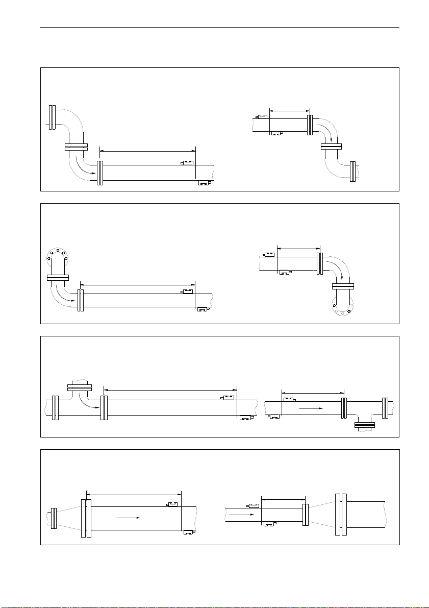
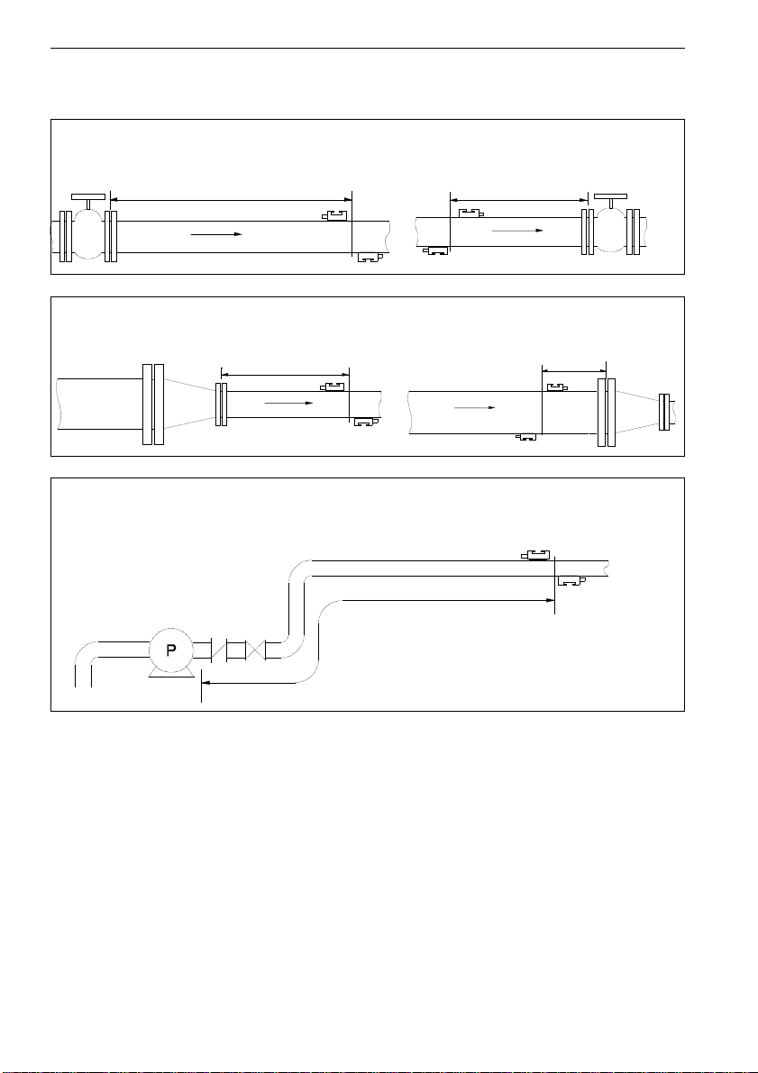
Recommended straight inlet and outlet pipe lengths are given for different types of flow
disturbance sources in the examples in Table 5.1.
Table 5.1: Recommended distance from disturbance sources
D = nominal pipe diameter at the measuring point, l = recommended distance
disturbance source: 90° elbow
supply: l 20D return: l 10 D
UMG70XV3-4EN 12.01.2009 31
Page 32
5 Selection of the Measuring Point
l
l
l
l
l
l
l
l
Table 5.1: Recommended distance from disturbance sources
D = nominal pipe diameter at the measuring point, L = recommended distance
disturbance source: 2x 90 ° elbows in one plane
supply: l 50D return: l 10 D
disturbance source: 2x 90 ° elbows in different planes
supply: l 80D return: l 10D
disturbance source: T piece
supply: l 100D return: l 20D
disturbance source: diffuser
supply: l 60D return: l 10 D
32 UMG70XV3-4EN 12.01.2009
Page 33
5 Selection of the Measuring Point
l
l
l
l
l
Table 5.1: Recommended distance from disturbance sources
D = nominal pipe diameter at the measuring point, L = recommended distance
disturbance source: valve
supply: l 80D return: l 20D
disturbance source: reducer
supply: l 20D return: l 10 D
disturbance source: compressor
supply: l 100D
UMG70XV3-4EN 12.01.2009 33
Page 34
5 Selection of the Measuring Point
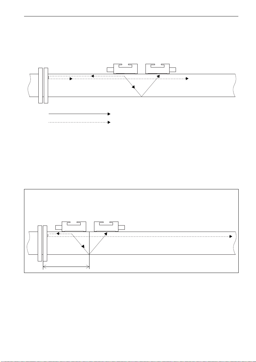
ultrasonic waves at the pipe wall (pipe wall signal)
ultrasonic waves in the medium (measuring signal)
disadvantageous
l
S
5.3 Influence of Noise
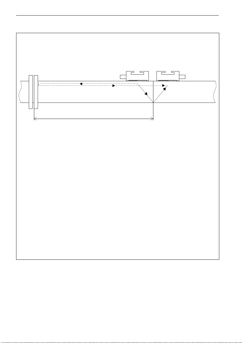
The ultrasonic waves do not propagate only in the medium but also in the pipe wall (see
Fig. 5.2). They will be reflected at flanges.
Fig. 5.2: Propagation of ultrasonic waves
The reflected pipe wall signals can disturb the measurement, especially if:
• the measuring point is close to the reflection point
• the pipe wall and measuring signals are received by the transducer at the same time
Table 5.2: Measuring points to be avoided
directly at the reflection point (lS < 3 D):
34 UMG70XV3-4EN 12.01.2009
Page 35
5 Selection of the Measuring Point
disadvantageous
l
s
l
s
n
2
-- -
c
P
c
F
----- -
D=
Table 5.2: Measuring points to be avoided
in the distance of lS ± 2 D from the reflection point
Pipe wall signal and measuring signal reach the transducer simultaneously.
- distance to reflection point
l
S
D - outer pipe diameter
- sound velocity in the medium
c
F
cP- sound velocity in the pipe
n - number of sound paths
example:
medium: natural gas
pipe material: stainless steel
: 3000 m/s
c
P
cF: 400 m/s
number of soundpaths: 2
= 7.5 D
l
S
The range (7.5 ± 2) D is disadvantageous for the transducer installation.
UMG70XV3-4EN 12.01.2009 35
Page 36

5 Selection of the Measuring Point
20D 20D
36D
(7.5 - 2) D
3D
5.4 Selection of the Measuring Point Taking into Account Flow
Profile and Influence of Noise
• Select a measuring point area where the flow profile is fully developed (see section
5.2).
• Select the measuring point within this area so that the influence of noise can be ne-
glected (see 5.3).
example: medium: natural gas
pipe material: stainless steel
length of pipe segment 1: 20 D
length of pipe segment 2: 20 D
number of sound paths: 2
• measuring point area with developed flow profile:
disturbance source: 90° elbow
recommended measuring point area: l 20 D (complete pipe segment 2) (see Table
5.1)
• measuring point area with low influence of noise:
reflection point: flange
recommended measuring point area: l 3 D and outside of l = (7.5 ± 2) D on pipe
segment 2 (see Table 5.1)
Fig. 5.3: Measuring point area with developed flow profile and low influence o f noise
Considering flow profile and influence of noise, the measuring point can be selected in
the area 3...(7.5 - 2) D on the right side of pipe segment 2 (with max. distance from the elbow). In the example, a distance of 36 D from the elbow was selected.
36 UMG70XV3-4EN 12.01.2009
Page 37

5 Selection of the Measuring Point
5D
20D
(7.5 - 2) D
3D
16 D
Both demands can not be observed always at the same time. In these cases, the measuring point has to be selected so that the influence of noise is min. and the measuring
point is as far as possible from disturbance sources of the flow profile.
example: medium: natural gas
pipe material: stainless steel
length of pipe segment 1: 20 D
length of pipe segment 2: 5 D
number of sound paths: 2
• measuring point area with developed flow profile:
disturbance source: 90° elbow
recommended measuring point area: l 20 D (complete pipe segment 2) (see Table
5.1)
• measuring point area with low influence of noise:
reflection point: flange
recommended measuring point area: l 3 D and outside of l = (7.5 ± 2) D on pipe
segment 1 (see Table 5.1)
Fig. 5.4: Measuring point area with low influence of noise and
not fully developed flow profile
In the example, there is no measuring point area where both demands are met at the
same time. The measuring point has to be selected as far as possible from the elbow, at
a point where the influence of noise can be neglected: 3...(7.5 - 2) D on the right side of
pipe segment 1. In the example, a distance of 16 D from the elbow was selected.
UMG70XV3-4EN 12.01.2009 37
Page 38

6 Installation of FLUXUS G704
163
265
200
35
Ø 3.5
Ø 6
M4
25
35
280
6 Installation of FLUXUS G704
6.1 Location
Select the measuring point according to the recommendations in chapter 5. The ambient
temperature must be within the operating temperature range of the transducers.
Select the location of the flowmeter within cable reach of the measuring point. The ambient temperature must be within the operating temperature range of the flowmeter (see
annex A, section Technical Data).
If the measuring point is within an explosive atmosphere, the danger zone and gases
which may be present have to be determined. The transducers and the flowmeter have
to be appropriate for these conditions.
Observe the safety instructions in chapter 2.
Attention! The flowmeter FLUXUS G704 must be operated outside of explosive
atmospheres.
The flowmeter FLUXUS G704 A2 must be operated outside of ATEX
zone 0 and 1.
Attention! The degree of protection of the flowmeter is only guaranteed if the
cable glands are firmly tightened and the housings have been tightly
screwed.
6.2 Wall Installation
Fig. 6.1: Wall installation (dimensions in mm)
38 UMG70XV3-4EN 12.01.2009
Page 39
6 Installation of FLUXUS G704
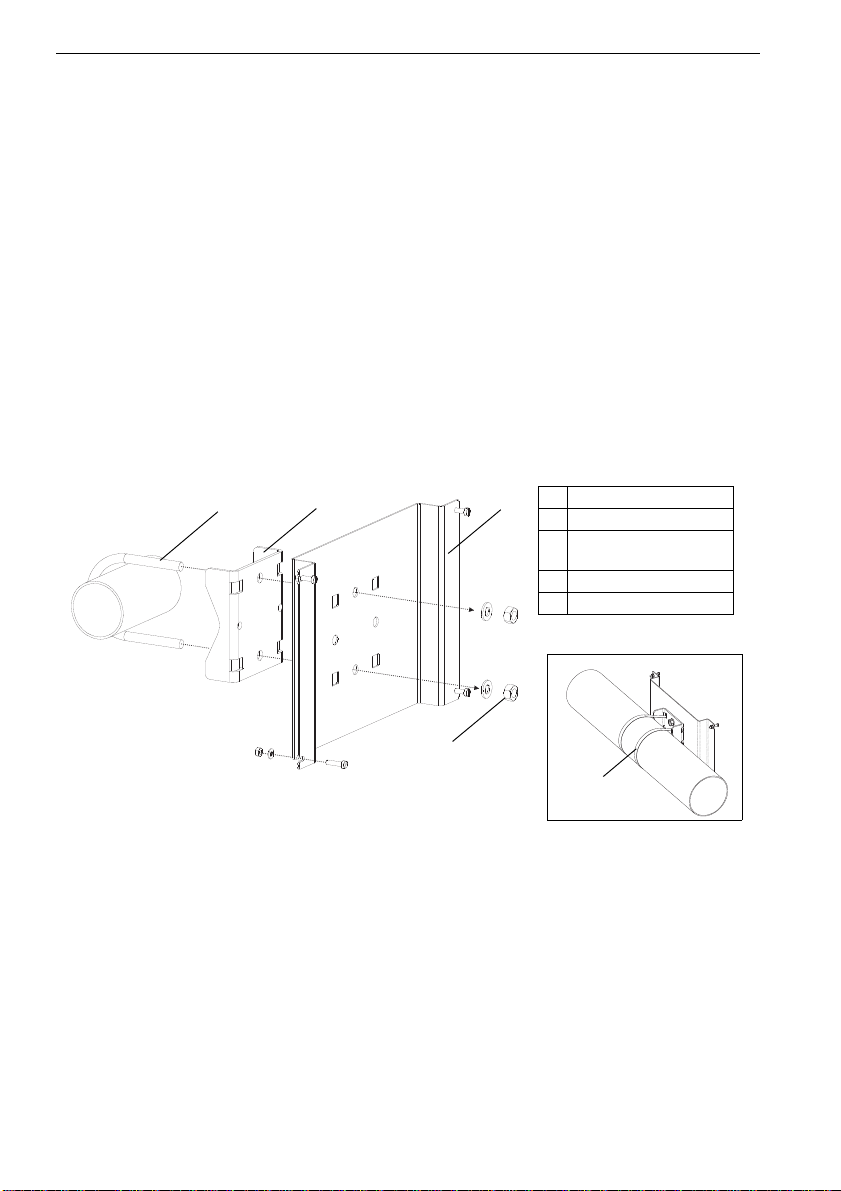
1 shackle
2
pipe mounting plate
3
instrument mounting
plate
4nut
5 tension strap
1
2
3
4
5
• Remove the cover of the housing.
• At the chosen location, drill 4 holes in the wall (see Fig. 6.1).
• Insert dowels in the holes.
• Fix the housing with screws to the wall.
6.3 Pipe Installation
Installation at 2 " pipe
• Fix the pipe mounting plate (2) to the pipe (see Fig. 6.2).
• Fix the instrument mounting plate (3) with the screws (4) to the pipe mounting plate (2).
• Fix the bottom side of the housing to the instrument mounting plate (3).
Installation at pipe > 2 "
The mounting kit will be fixed with tension straps (5) instead of the shackle (see Fig. 6.2).
Push the tension straps through the holes of the instrument mounting plate (3).
Fig. 6.2: Pipe installation set
UMG70XV3-4EN 12.01.2009 39
Page 40

6 Installation of FLUXUS G704
6.4 Connection of the Transducers - Connection System TS
Note! If transducers are replaced or added, the sensor module has to be
replaced or added, too (see section 6.10).
It is recommended to run the cables from the measuring point to the flowmeter before the
connection of the transducers to avoid load on the connection points.
Overview
section page
6.4.1 Transducers (ATEX Zone 1) - Direct Connection..............................................40
6.4.2 Transducers (ATEX Zone 1) - Connection via Junction Box .............................42
Connection of the Extension Cable with the Flowmeter ....................................42
Connection of the Extension Cable with the Junction Box ................................43
Connection of the Transducer Cable with the Junction Box..............................45
6.4.3 Transducers (ATEX Zone 2, FM Div. 2 and without Explosion Protection) -
Direct Connection..............................................................................................46
6.4.4 Transducers (ATEX Zone 2, FM Div. 2 and without Explosion Protection) -
Connection via Junction Box .............................................................................47
Connection of the Extension Cable with the Flowmeter ....................................47
Connection of the Extension Cable with the Junction Box ................................48
Connection of the Transducer Cable with the Junction Box..............................48
6.4.1 Transducers (ATEX Zone 1) - Direct Connection
Observe the safety instructions in chapter 2.
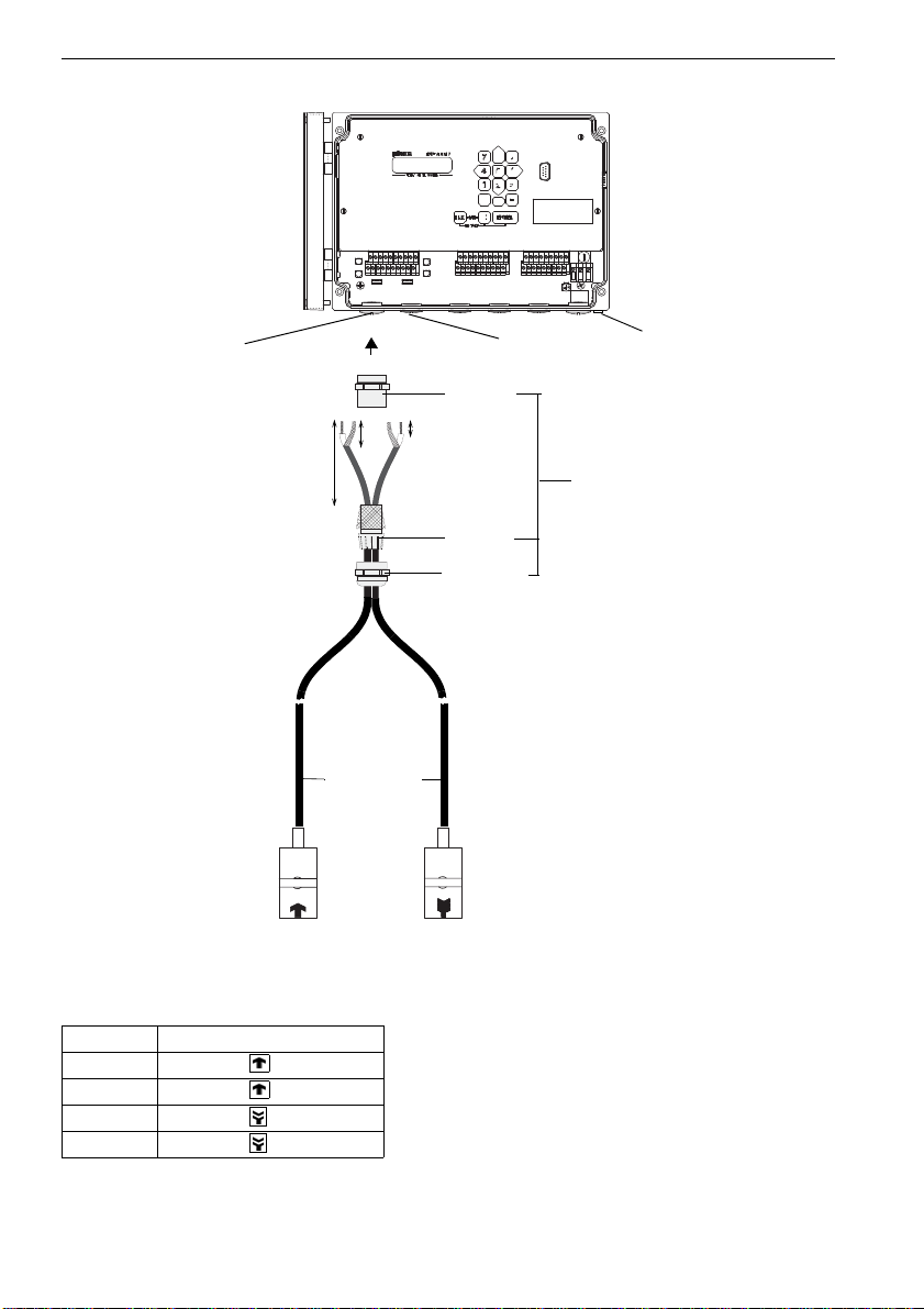
• Remove the left blind plug for the connection of the transducers (see Fig. 6.3).
• Open the cable gland of the transducer cable. The compression part remains in the
cap nut.
• Push both transducer cables through cap nut and compression part.
• Prepare the transducer cables with the cable gland. Cut the outer shield and brush it
back.
• Tighten the gasket ring side of the basic part in the housing.
• Insert the transducer cable in the housing.
• Fix the cable gland by screwing the cap nut on the basic part.
Attention! For good high frequency shielding it is important to assure good con-
tact between the cable shield and the cap nut (and thus the housing).
• Connect the leads to the terminals of the flowmeter (see Fig. 6.3 and Table 6.1).
40 UMG70XV3-4EN 12.01.2009
Page 41
6 Installation of FLUXUS G704
transducers
measuring channel B
cable gland
with double hole sealing
basic
part
transducers
ATEX zone 1
20 mm
70 mm
10 mm
transducer
cable
transducers
measuring channel A
equipotential bonding
terminal
(FLUXUS G704 A2)
compression part
cap nut
Fig. 6.3: Transducers ATEX zone 1 - direct connection
Table 6.1: Terminal assignment
terminal connection
AV transducer (core)
AVS transducer (inner shield)
ARS transducer (inner shield)
AR transducer (core)
UMG70XV3-4EN 12.01.2009 41
Page 42
6 Installation of FLUXUS G704
70 mm
20 mm
10 mm
basic
part
compression part
cap nut
extension cable
cable gland
transducers
measuring channel A
transducers
measuring channel B
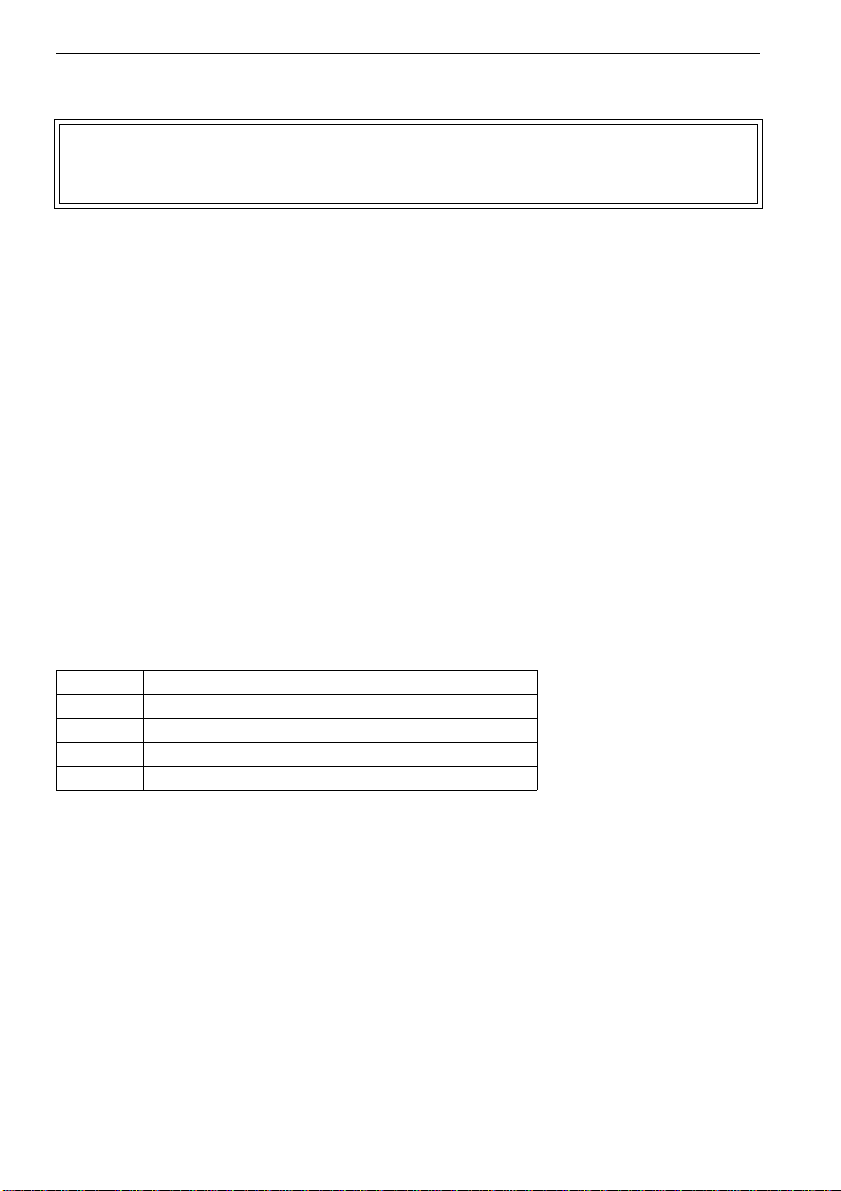
6.4.2 Transducers (ATEX Zone 1) - Connection via Junction Box
Connection of the Extension Cable with the Flowmeter
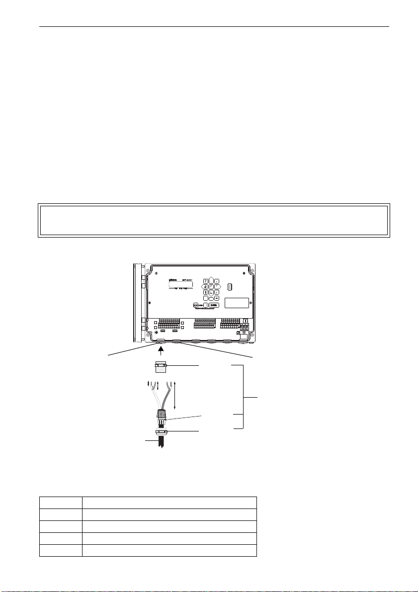
• Remove the left blind plug for the connection of the transducers (see Fig. 6.4 ).
• Open the cable gland of the extension cable. The compression part remains in the cap
nut.
• Push the extension cable through the cap nut and the compression part.
• Prepare the extension cable with the cable gland. Cut the outer shield and brush it
back.
• Tighten the gasket ring side of the basic part in the housing.
• Insert the extension cable in the housing.
• Fix the cable gland by screwing the cap nut on the basic part.
Attention! For good high frequency shielding it is important to assure good con-
tact between the cable shield and the cap nut (and thus the housing).
• Connect the leads to the terminals of the flowmeter (see Fig. 6.4 and Table 6.2).
Table 6.2: Terminal assignment
terminal connection
AV white or marked cable (core)
AVS white or marked cable (inner shield)
ARS brown cable (inner shield)
AR brown cable (core)
42 UMG70XV3-4EN 12.01.2009
Fig. 6.4: Transducers (ATEX zone 1) - connection via junction box,
connection of the extension cable to the flowmeter
Page 43
6 Installation of FLUXUS G704
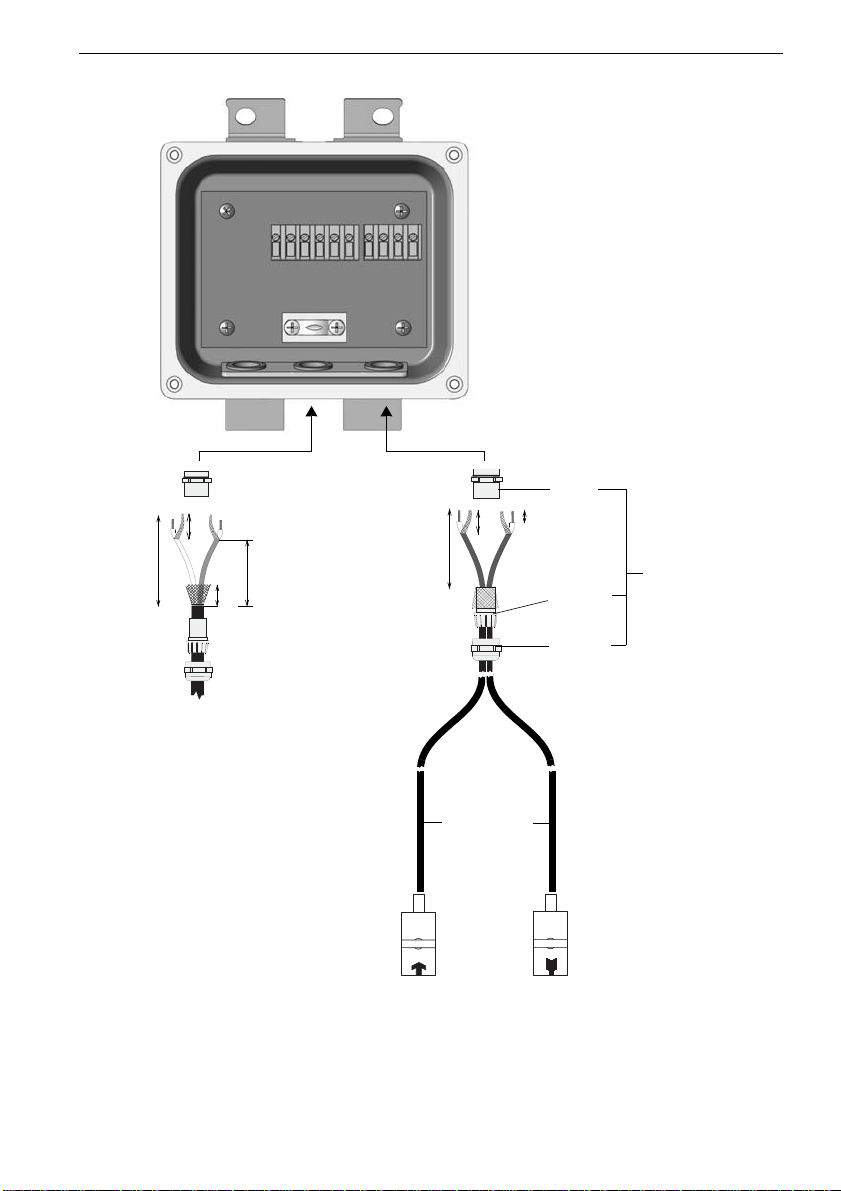
Connection of the Extension Cable with the Junction Box
Attention! The outer shield of the extension cable must not have electrical con-
tact to the junction box. The extension cable has to remain insulated
completely up to the shield terminal of the junction box.
• Remove the blind plug from the housing (see Fig. 6.5).
• Open the cable gland of the extension cable. The compression part remains in the cap
nut.
• Push the extension cable through cap nut, compression part and basic part.
• Insert the extension cable in the junction box.
• Prepare the extension cable with the cable gland. Cut the outer shield and brush it
back.
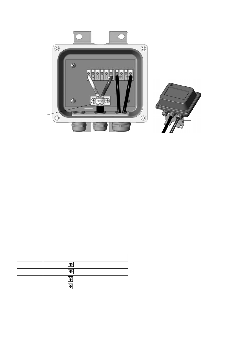
• Pull the extension cable back until the brushed back outer shield is below the shield
terminal (see Fig. 6.6).
• Tighten the gasket ring side of the basic part in the junction box.
• Fix the cable gland by screwing the cap nut on the basic part.
• Fix the extension cable and the outer shield to the shield terminal of the junction box
(see Fig. 6.6).
• Connect the leads of the extension cable to the terminals of the junction box (see Fig.
6.6 and Table 6.3).
Table 6.3: Terminal assignment
terminal connection
TV white or marked cable (core)
TVS white or marked cable (inner shield)
TRS brown cable (inner shield)
TR brown cable (core)
UMG70XV3-4EN 12.01.2009 43
Page 44
6 Installation of FLUXUS G704
20 mm
10 mm
100 mm
transducer
cable
transducers
ATEX zone 1
cable gland
basic
part
compression part
cap nut
100 mm
75 mm
12 mm
extension cable
20 mm
Fig. 6.5: Transducers (ATEX zone 1) - connection via junction box,
connection of extension cable and transducer cable
44 UMG70XV3-4EN 12.01.2009
to the junction box
Page 45
6 Installation of FLUXUS G704
shield terminal
equipotential
bonding terminal
TV TVS TG TG TRS TR V VS RS R
Fig. 6.6: Connection of extension cable and transducer cable (ATEX zone 1)
Connection of the Transducer Cable with the Junction Box
• Remove the blind plug from the junction box (see Fig. 6.5).
• Open the cable gland of the transducer cable. The compression part remains in the
cap nut.
• Push the transducer cable through cap nut, compression part and basic part.
• Prepare the transducer cable with the cable gland. Cut the outer shield and brush it
back.
• Insert the transducer cable in the junction box.
• Tighten the gasket ring side of the basic part in the junction box.
• Fix the cable gland by screwing the cap nut on the basic part.
• Connect the leads to the terminals of the junction box (see Fig. 6.6 and Table 6.4).
Table 6.4: Terminal assignment
terminal connection
V transducer (core)
VS transducer (inner shield)
RS transducer (inner shield)
R transducer (core)
UMG70XV3-4EN 12.01.2009 45
Page 46
6 Installation of FLUXUS G704
SMB connector
transducers:
• ATEX zone 2
• FM Div. 2
• without explosion protection
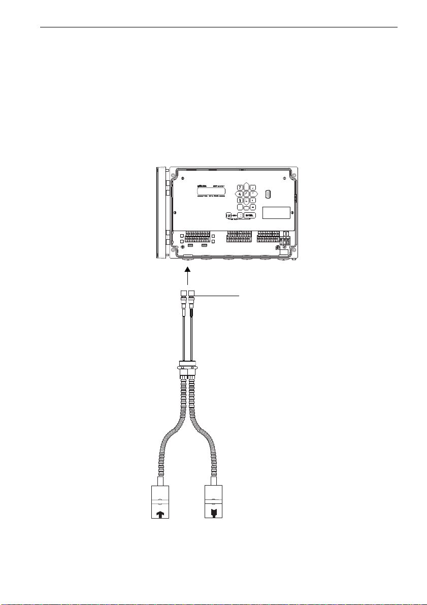
6.4.3 Transducers (ATEX Zone 2, FM Div. 2, without Explosion
Protection) - Direct Connection
Observe the safety instructions in chapter 2.
• Remove the left blind plug for the connection of the transducers (see Fig. 6.7).
• Insert the transducer cable with the SMB connectors in the housing.
• Fix the transducer cable by tightening the cable gland.
• Connect the SMB connectors with the sockets of the flowmeter (see Fig. 6.7 and Table
6.5).
Fig. 6.7: Transducers (ATEX zone 2, FM Div. 2, without explosion protection)
- direct connection
46 UMG70XV3-4EN 12.01.2009
Page 47

6 Installation of FLUXUS G704
70 mm
20 mm
10 mm
basic
part
compression part
cap nut
extension cable
cable gland
transducers
measuring
channel A
transducers
measuring
channel B
Table 6.5: Terminal assignment
terminal connection
X_AV SMB connector (brown cable, marked white)
X_AR SMB connector (brown cable, marked black)
6.4.4 Transducers (ATEX Zone 2, FM Div. 2, without Explosion
Protection) - Connection via Junction Box
Connection of the Extension Cable with the Flowmeter
• Remove the left blind plug for the connection of the transducers (see Fig. 6.8).
• Open the cable gland of the extension cable. The compression part remains in the cap
nut.
• Push the extension cable through the cap nut and the compression part.
• Prepare the extension cable with the cable gland. Cut the outer shield and brush it
back.
• Tighten the gasket ring side of the basic part in the housing.
• Insert the extension cable in the housing.
• Fix the cable gland by screwing the cap nut on the basic part.
Attention! For good high frequency shielding it is important to assure good con-
tact between the cable shield and the cap nut (and thus the housing).
• Connect the leads to the terminals of the flowmeter (see Fig. 6.8 and Table 6.6).
Fig. 6.8: Transducers (ATEX zone 2, FM Div. 2, without explosion protection) -
connection via junction box, connection with the flowmeter
UMG70XV3-4EN 12.01.2009 47
Page 48
6 Installation of FLUXUS G704
Table 6.6: Terminal assignment
terminal connection
AV white or marked cable (core)
AVS white or marked cable (inner shield)
ARS brown cable (inner shield)
AR brown cable (core)
Connection of the Extension Cable with the Junction Box
Attention! The outer shield of the extension cable must not have electrical con-
tact to the junction box. The extension cable has to remain insulated
completely up to the shield terminal.
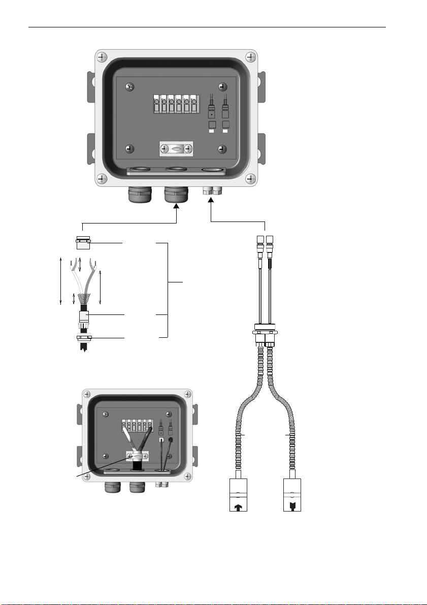
• Remove the blind plug from the housing (see Fig. 6.9).
• Open the cable gland of the extension cable. The compression part remains in the cap
nut.
• Push the extension cable through cap nut, compression part and basic part.
• Insert the extension cable in the junction box.
• Prepare the extension cable with the cable gland. Cut the outer shield and brush it
back.
• Pull the extension cable back until the brushed back outer shield is below the shield
terminal (see Fig. 6.9).
• Tighten the gasket ring side of the basic part in the junction box.
• Fix the cable gland by screwing the cap nut on the basic part.
• Fix the extension cable and the outer shield to the shield terminal of the junction box
(see Fig. 6.9).
• Connect the leads to the terminals of the junction box (see Fig. 6.9 and Table 6.7).
Table 6.7: Terminal assignment
terminal connection
TV white or marked cable (core)
TVS white or marked cable (inner shield)
TRS brown cable (inner shield)
TR brown cable (core)
Connection of the Transducer Cable with the Junction Box
• Remove the blind plug from the junction box (see Fig. 6.9).
• Insert the transducer cable with the SMB connectors in the housing.
• Fix the transducer cable by tightening the cable gland.
• Connect the SMB connectors with the sockets of the flowmeter (see Fig. 6.9 and Table
6.4).
Table 6.8: Terminal assignment
terminal connection
XV SMB connector (brown cable, marked white)
XR SMB connector (brown cable, marked black)
48 UMG70XV3-4EN 12.01.2009
Page 49
6 Installation of FLUXUS G704
100 mm
75 mm
12 mm
transducers:
• ATEX zone 2
• FM Div. 2
• without explosion
protection
transducer
cable
extension cable
shield terminal
basic
part
compression part
cap nut
cable gland
TV TVS TG TG TRS TR
XV
XR
20 mm
Fig. 6.9: Transducers (ATEX zone 2, FM Div. 2, without explosion protection) -
connection via junction box, connection of extension cable and transducer cable
to the junction box
UMG70XV3-4EN 12.01.2009 49
Page 50

6 Installation of FLUXUS G704
AMP-Quick and
SMB connectors
cable gland
transducers:
• ATEX zone 2
• FM Div. 2
• without explosion protection
6.5 Connection of the Transducers - Connection System AS
• Remove the left blind plug for the connection of the transducers (see Fig. 6.10).
• Insert the extension cable with the AMP-Quick and SMB connectors in the housing.
• Fix the extension cable by tightening the cable gland.
• Connect the AMP-Quick and the SMB connectors with the sockets of the flowmeter
(see Fig. 6.10 and Tabelle 6.9).
Fig. 6.10: Transducers (ATEX zone 2, FM Div. 2, without explosion protection) -
direct connection
Tabelle 6.9: Terminal assignment
terminal connection
X_AV SMB connector (white or marketd cable)
X_AR SMB connector (brown cable)
X1 AMP-Quick connector
50 UMG70XV3-4EN 12.01.2009
Page 51
6 Installation of FLUXUS G704
power supply
(KL3)
KL3
6.6 Connection of the Power Supply
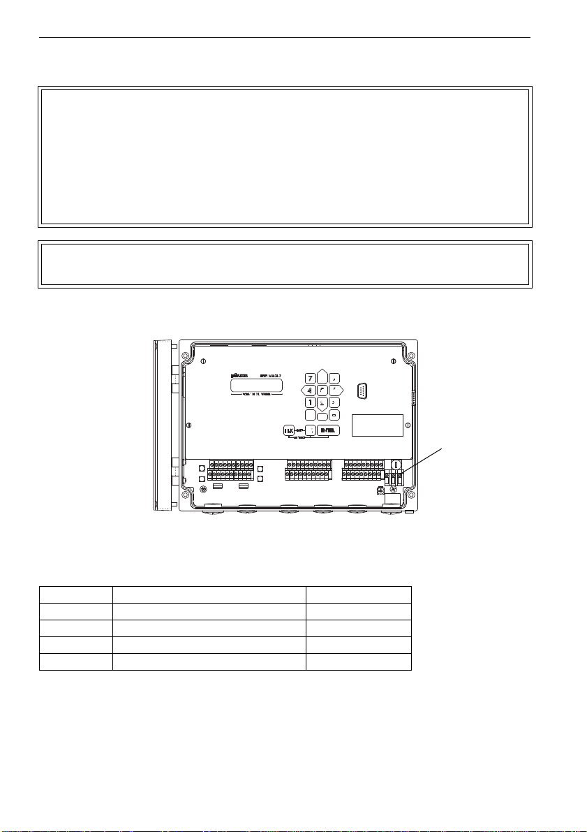
Attention! A switch according to IEC 61010-1:2001 has to be provided in the
building installation which must be near the instrument, easily accessible for the user and marked as disconnection devi ce of the instrument.
If the flowmeter FLUXUS G704 A2 is used in explosive atmosphere,
the switch should be installed outside the explosive atmosphere. If
this is not possible, the switch should be installed in the area with the
least risk.
Attention! The degre e of protection of the flowmeter is only guaranteed if the
power cable fits firmly and tightly in the cable gland.
• Prepa re the power cable. Connect the leads with the terminals of the power supply
(see Fig. 6.11 and Table 6.10).
Fig. 6.11: Connection of the power supply
Table 6.10: Terminal assignment (power supply)
terminal connection AC connection DC
PE earth earth
N(-) neutral -DC
L(+) phase 100...240 V AC, 50/60 Hz +DC
fuse 1 A, time-lag 1.6 A, time-lag
UMG70XV3-4EN 12.01.2009 51
Page 52
6 Installation of FLUXUS G704
I1 active loop
Terminal:P1+,P1-
outputs
(KL4)
+
-
mA
+-
+
-
mA
+-
6.7 Connection of the Outputs
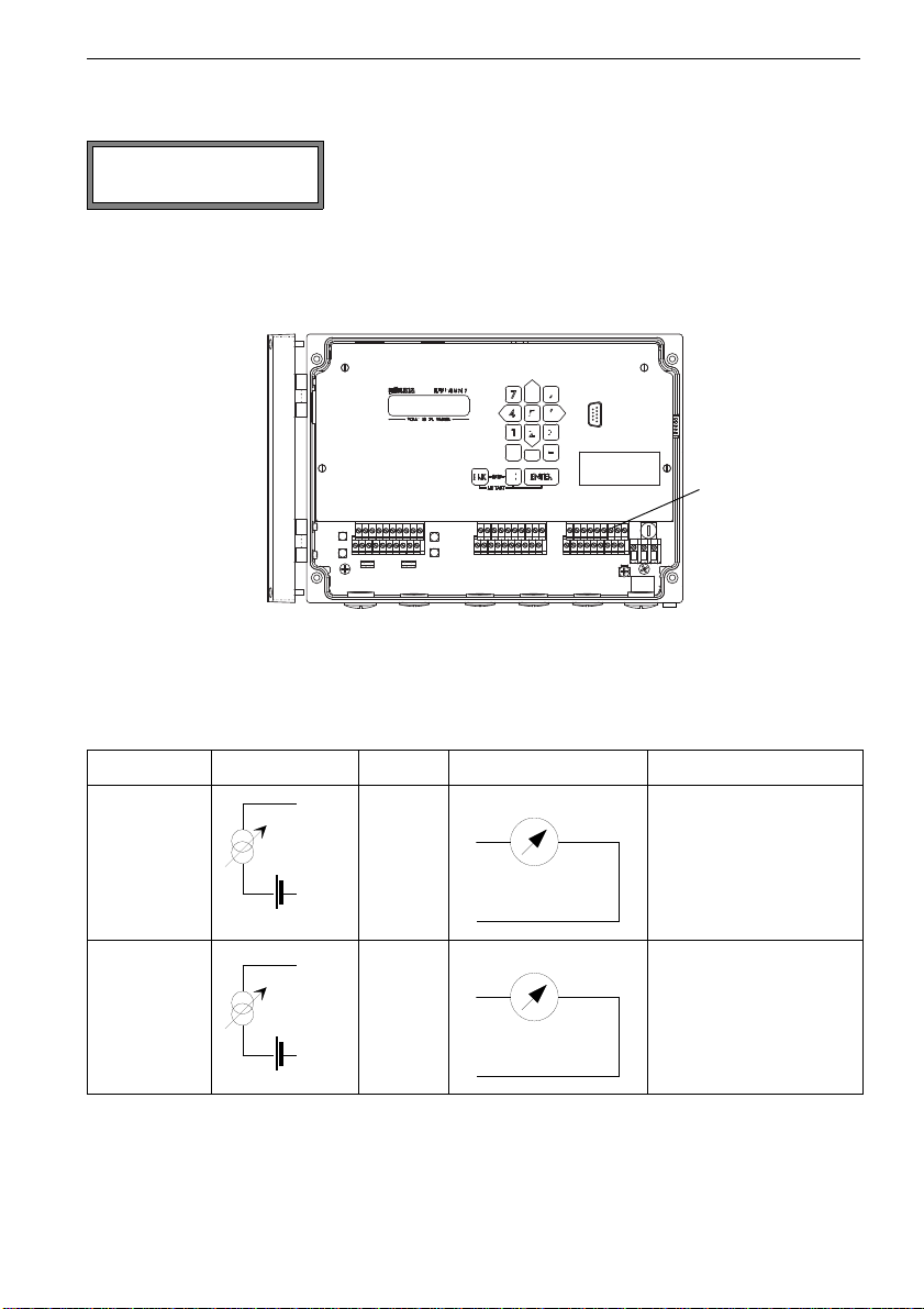
Configure the outputs (see chapter 18). The terminals
to be used for the connection of the output are displayed at the end of the configuration dialog (here: P1+
and P1- for the active current loop).
• Prepare the output cable. Connect the leads with the terminals of the outputs as displayed (see Fig. 6.12 and Table 6.11).
Fig. 6.12: Connection of the outputs
• Close the flowmeter: Screw the cover on the housing.
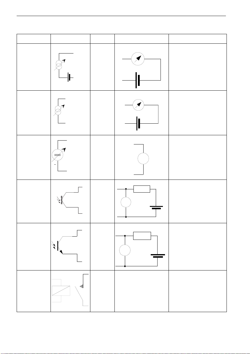
Table 6.11: Circuits of the outputs
output FLUXUS terminal circuits
active
current loop
semi-active
current loop
operated as
active current
loop
52 UMG70XV3-4EN 12.01.2009
Px+
(red)
(black)
Px-
Px+
(red)
(black)
Px-
R
R
LOAD
LOAD
< 500
< 50
Page 53
6 Installation of FLUXUS G704
+
-
mA
+-
+
-
U
H
mA
+-
+
-
U
H
+
Ri=500
Ri = 500
V
+
-
+
-
U
H
V
+
-
R
C
+
-
U
H
V
+
-
R
C
a
b
Table 6.11: Circuits of the outputs
output FLUXUS terminal circuits
semi-active
current loop
Px+
(red)
operated as
passive current loop
(black)
Px-
U
= 0...24 V
H
> 0.021A . R
U
H
LOAD
[]
passive
current loop
voltage
output
binary output
(optorelay)
binary output
(open
collector)
(special
design)
Px+
(red)
(black)
Px-
Px+
(red)
(black)
Px-
Px+
(red)
(black)
Px-
Px+
(red)
(black)
Px-
= 5...25 V
U
H
>0.021A.R
U
H
= 12 V, R
If U
H
be in the range 0...380 .
> 2 M
R
LOAD
If R
is lower, the
LOAD
accuracy is lower than
LOAD
LOAD
[]+4V
must
specified.
U
< 32 V
H
≤ 100 mA
I
c
U
= 5...24 V
H
[k] = UH/Ic [mA]
R
C
I
= 1...4 mA
c
binary output
(Reed relay)
Px+
Pxa
U
I
MAX
MAX
= 24 V
= 150 mA
(special
design)
Pxb
Px-
R
is the sum of all ohmic resistances in the circuit (resistance of the conductors, inner resis-
LOAD
tance of the external power supply, resistance of the amperemeter/voltmeter, etc.)
UMG70XV3-4EN 12.01.2009 53
Page 54
6 Installation of FLUXUS G704
+
-
Txb
TxA
6.8 Connection of the Inputs
Max. 4 temperature probes Pt100/Pt1000 (4-wire) can be connected to the flowmeter
(option).
Configure the temperature inputs (see chapter 17).
Table 6.12: Terminal assignment of the flowmeter
terminal connection with
extension cable
Txa red red
TxA gray red/blue
Txb blue white/blue
TxB white white
Sx Pt100/Pt1000 shield Pt100/Pt1000 shield
x = 1...4
6.8.1 Connection of a Current Input
An active current source has to be connected to a passive current input. A passive current source can be connected directly to an active current input, or to a passive current
input via an external power supply.
Connection of a Passive Current Source
At full load (20 mA), a voltage of min. 13 V DC is available for the supply of a passive current source.
Terminal TxA is on the upper, Txb on the lower terminal row (x = 1...4).
connection without
extension cable
Fig. 6.13: Connection of an external passive current source
Attention! The terminals Txa and TxB must not be connected.
Attention! Observe the polarity to avoid damage of the current source. The cur-
rent input could be destroyed by a permanent shorting of both terminals.
54 UMG70XV3-4EN 12.01.2009
Page 55

6 Installation of FLUXUS G704
-
+
TxB TxA
If the flowmeter has a passive current input, an external power supply is necessary. The
power supply U
must be able to
H
• supply sufficient power for the energy requirements of the passive current source
• cover the voltage drop over the measurement resistance (max. 1 V) and
• cover all other voltage drops (e.g. cable resistance) in the circuit.
A current of min. 20 mA has to be provided.
example: A passive current source (e.g. a pressure sensor) is connected to a passive
current input.
technical data of the pressure sensor:
auxiliary power supply: U
output signal: I
= 4...20 mA
A
= 11...30 V DC
S
The required auxiliary power supply of the pressure sensor will be calculated as follows:
U
H min
= U
R
R
+ I
S min
mea
cab
A max
- input impedance
- cable resistance)
· R
mea
+ I
A max
· R
cab
= 11 V + 20 mA · 50 + 20 mA · 2
= 12.04 V
U
H max
= 30 V (according to specification of the supplier)
Connection of an Active Current Source
Attention! Never connect an active current source to an active current input!
The terminals TxA and TxB are on the upper terminal row (x =1...4)
If the polarity of the current source is inversed, only the sign of the measured current will
change.
Fig. 6.14: Connection of an active current source
Attention! The terminals Txa and Txb must not be connected.
UMG70XV3-4EN 12.01.2009 55
Page 56

6 Installation of FLUXUS G704
serial interface RS485
(option)
(KL4)
serial interface RS232
Table 6.13: Technical data of the current input
active passive
measuring range 0...+20 mA -20...+20 mAâ
accuracy 0.1% v. MW 10 µA 0.1% v. MW 10 µA
input impedance 50 /0.6 W 50 /0.6 W
short circuit current 100 mA 100 mA
6.9 Connection of the Serial Interface
The RS232 interface is located on the front plate of the flowmeter (see Fig. 6.15).
The flowmeter can be equipped with an RS485 interface (option). Connect the RS485
cable to the terminals A+ and B- and terminal 101 of terminal strip KL4 (see Fig. 6.15).
For further information on the data transmission see chapter 13.
Fig. 6.15: Connection of the serial interface
6.10 Connection of the Sensor Module (SENSPROM)
The sensor module contains important transducer data for the operation of the flowmeter
with the transducers. It is connected with the corresponding terminals of the flowmeter.
If transducers are replaced or added, the sensor module has to be replaced or added,
too.
Note! The serial number of sensor module and transducer have to be iden-
tical. A wrong or incorrectly connected sensor module will result in incorrect measured values or in measurement failure.
56 UMG70XV3-4EN 12.01.2009
Page 57

6 Installation of FLUXUS G704
sensor module
(KL1)
• Stop the measurement.
• Insert the sensor module in the lower row of terminal strip KL1 (see Fig. 6.16). The
transducers of measuring channel A are connected to SA1...SA4, the transducers of
measuring channel B to SB1...SB4.
• Edit the program branch PARAMETER once completely. Press ENTER until the main
menu is displayed again.
• The measurement can be restarted afterwards.
Fig. 6.16: Connection of the sensor module (SENSPROM)
UMG70XV3-4EN 12.01.2009 57
Page 58
7 Installation of FLUXUS G709
7 Installation of FLUXUS G709
7.1 Location
Select the measuring point according to the recommendations in chapter 5. The ambient
temperature must be within the operating temperature range of the transducers.
Select the location of the flowmeter within cable reach of the measuring point. The ambient temperature must be within the operating temperature range of the flowmeter (see
annex A, section Technical Data).
If the measuring point is within an explosive atmosphere, the danger zone and gases
which may be present have to be determined. The transducers and the flowmeter have
to be appropriate for these conditions.
Observe the safety instructions in chapter 2.
Attention! The flowmeter FLUXUS G709 must be operated outside of explosive
atmospheres.
7.2 Connection of the Transducers - Connection System TS
Note! If transducers are replaced or added, the sensor module has to be
replaced or added, too (see section 7.8).
It is recommended to run the cables from the measuring point to the flowmeter before the
connection of the transducers to avoid load on the connection points.
Overview
section page
7.2.1 Transducers (ATEX Zone 1) - Connection via Junction Box .............................59
Connection of the Extension Cable with the Flowmeter ....................................59
Connection of the Extension Cable with the Junction Box ................................60
Connection of the Transducer Cable with the Junction Box..............................62
7.2.2 Transducers (ATEX Zone 2, FM Div. 2 and without Explosion Protection -)
Connection via Junction Box .............................................................................63
Connection of the Extension Cable with the Flowmeter ....................................63
Connection of the Extension Cable with the Junction Box ................................64
Connection of the Transducer Cable with the Junction Box..............................64
58 UMG70XV3-4EN 12.01.2009
Page 59

7 Installation of FLUXUS G709
50 mm
20 mm
60 mm
extension cable
shield terminal
T 1 A
T 1 B
P T 1 0 0
T 4 B
T 4 A
P T 1 0 0
B :A :
S A 3
S A 1
S A 2
S A 4
S B 3
S B 1
S B 2
S B 4
A V S
A V
A R S
A G N
A R
B V S
B V
B R S
B G N
B R
A C
2 3 0 V
1 0 0 . . .
D C
V O L T
L O W
4 A +
4 B -
4 2
4 3
4 1
L +
L -
N
L 1
P E
P 4 +
P 5 +
P 2 +
P 3 +
P 1 +
P 6 a
P 7 a
P 7 +
P 5 a
P 6 +
P 4 -
P 5 -
P 2 -
P 3 -
P 1 -
P 6 b
P 7 b
P 7 -
P 5 b
P 6 -
T 2 A
T 2 B
T 1 B
S 1
T 1 A
T 4 A
T 4 B
T 3 B
S 3
T 3 A
T 2 a
T 2 b
T 1 b
S 2
T 1 a
T 4 a
T 4 b
T 3 b
S 4
T 3 a
KL1 KL3 KL5 KL7
KL2 KL4
KL6 KL8
7.2.1 Transducers (ATEX Zone 1) - Connection via Junction Box
Connection of the Extension Cable with the Flowmeter
• Prepare the extension cable. Cut the outer shield and brush it back.
• Push the extension cable through the shield terminal to terminal strip KL6 for measuring channel A and to terminal strip KL8 for measuring channel B (see Fig. 7.2).
• Pull the extension cable back until the brushed back outer shield is below the shield
terminal (see Fig. 7.2).
• Fix the extension cable and the outer shield to the shield terminal.
• Connect the leads to the terminals of the flowmeter (see Table 7.1).
Table 7.1: Terminal assignment
terminal connection
AV white or marked cable (core)
Fig. 7.1: Transducers (ATEX zone 1) - connection via junction box,
connection of the extension cable to the flowmeter
AVS white or marked cable (inner shield)
ARS brown cable (inner shield)
AR brown cable (core)
UMG70XV3-4EN 12.01.2009 59
Page 60
7 Installation of FLUXUS G709
Connection of the Extension Cable with the Junction Box
Attention! The outer shield of the extension cable must not have electrical con-
tact to the junction box. The extension cable has to remain insulated
completely up to the shield terminal of the junction box.
• Remove the blind plug from the housing (see Fig. 7.2).
• Open the cable gland of the extension cable. The compression part remains in the cap
nut.
• Push the extension cable through cap nut, compression part and basic part.
• Insert the extension cable in the junction box.
• Prepare the extension cable with the cable gland. Cut the outer shield and brush it
back.
• Pull the extension cable back until the brushed back outer shield is below the shield
terminal (see Fig. 7.3).
• Tighten the gasket ring side of the basic part in the junction box.
• Fix the cable gland by screwing the cap nut on the basic part.
• Fix the extension cable and the outer shield to the shield terminal of the junction box
(see Fig. 7.3).
• Connect the leads to the terminals of the junction box (see Fig. 7.3 and Table 7.2).
Table 7.2: Terminal assignment
terminal connection
TV white or marked cable (core)
TVS white or marked cable (inner shield)
TRS brown cable (inner shield)
TR brown cable (core)
60 UMG70XV3-4EN 12.01.2009
Page 61

7 Installation of FLUXUS G709
20 mm
10 mm
100 mm
transducer
cable
transducers
ATEX zone 1
cable gland
basic
part
compression part
cap nut
100 mm
75 mm
12 mm
extension cable
20 mm
Fig. 7.2: Transducers (ATEX zone 1) - connection via junction box,
connection of extension cable and transducer cable to the junction box
UMG70XV3-4EN 12.01.2009 61
Page 62

7 Installation of FLUXUS G709
shield terminal
equipotential
bonding terminal
TV TVS TG TG TRS TR V VS RS R
Fig. 7.3: Connection of extension cable and transducer cable (ATEX zone 1)
Connection of the Transducer Cable with the Junction Box
• Remove the blind plug from the junction box (see Fig. 7.2).
• Open the cable gland of the transducer cable. The compression part remains in the
cap nut.
• Push the transducer cable through cap nut, compression part and basic part.
• Prepare the transducer cable with the cable gland. Cut the outer shield and brush it
back.
• Insert the transducer cable in the junction box.
• Tighten the gasket ring side of the basic part in the junction box.
• Fix the cable gland by screwing the cap nut on the basic part.
• Connect the leads to the terminals of the junction box (see Fig. 7.2 and Table 7.3).
Table 7.3: Terminal assignment
62 UMG70XV3-4EN 12.01.2009
terminal connection
V transducer (core)
VS transducer (inner shield)
RS transducer (inner shield)
R transducer (core)
Page 63

7 Installation of FLUXUS G709
50 mm
20 mm
60 mm
extension cable
shield terminal
T 1 A
T 1 B
P T 1 0 0
T 4 B
T 4 A
P T 1 0 0
B :A :
S A 3
S A 1
S A 2
S A 4
S B 3
S B 1
S B 2
S B 4
A V S
A V
A R S
A G N
A R
B V S
B V
B R S
B G N
B R
A C
2 3 0 V
1 0 0 . . .
D C
V O L T
L O W
4 A +
4 B -
4 2
4 3
4 1
L +
L -
N
L 1
P E
P 4 +
P 5 +
P 2 +
P 3 +
P 1 +
P 6 a
P 7 a
P 7 +
P 5 a
P 6 +
P 4 -
P 5 -
P 2 -
P 3 -
P 1 -
P 6 b
P 7 b
P 7 -
P 5 b
P 6 -
T 2 A
T 2 B
T 1 B
S 1
T 1 A
T 4 A
T 4 B
T 3 B
S 3
T 3 A
T 2 a
T 2 b
T 1 b
S 2
T 1 a
T 4 a
T 4 b
T 3 b
S 4
T 3 a
KL1 KL3 KL5 KL7
KL2 KL4
KL6 KL8
7.2.2 Transducers (ATEX Zone 2, FM Div. 2, without Explosion
Protection) - Connection via Junction Box
Connection of the Extension Cable with the Flowmeter
• Prepare the extension cable. Cut the outer shield and brush it back.
• Push the extension cable through the shield terminal to terminal strip KL6 for measur-
ing channel A and to terminal strip KL8 for measuring channel B (see Fig. 7.4).
• Pull the extension cable back until the brushed back outer shield is below the shield
terminal (see Fig. 7.4).
• Fix the extension cable and the outer shield to the shield terminal.
• Connect the leads to the terminals of the flowmeter (see Fig. 7.4 and Table 7.4).
Fig. 7.4: Transducers (ATEX zone 2, FM Div. 2, without explosion protection) -
Table 7.4: Terminal assignment
terminal connection
AV white or marked cable (core)
AVS white or marked cable (inner shield)
ARS brown cable (inner shield)
AR brown cable (core)
UMG70XV3-4EN 12.01.2009 63
connection via junction box,
connection with the flowmeter
Page 64
7 Installation of FLUXUS G709
Connection of the Extension Cable with the Junction Box
Attention! The outer shield of the extension cable must not have electrical con-
tact to the junction box. The extension cable has to remain insulated
completely up to the shield terminal.
• Remove the blind plug from the housing (see Fig. 7.5).
• Open the cable gland of the extension cable. The compression part remains in the cap
nut.
• Push the extension cable through cap nut, compression part and basic part.
• Insert the extension cable in the junction box.
• Prepare the extension cable with the cable gland. Cut the outer shield and brush it
back.
• Pull the extension cable back until the brushed back outer shield is below the shield
terminal (see Fig. 7.5).
• Tighten the gasket ring side of the basic part in the junction box.
• Fix the cable gland by screwing the cap nut on the basic part.
• Fix the extension cable and the outer shield to the shield terminal of the junction box
(see Fig. 7.5).
• Connect the leads to the terminals of the junction box (see Fig. 7.5 and Table 7.5).
Table 7.5: Terminal assignment
terminal connection
TV white or marked cable (core)
TVS white or marked cable (inner shield)
TRS brown cable (inner shield)
TR brown cable (core)
Connection of the Transducer Cable with the Junction Box
• Remove the blind plug from the junction box (see Fig. 7.5).
• Insert the transducer cable with the SMB connectors in the housing.
• Fix the transducer cable by tightening the cable gland.
• Connect the SMB connectors with the sockets of the flowmeter (see Fig. 7.5 and Table
7.3).
Table 7.6: Terminal assignment
terminal connection
XV SMB connector (brown cable, marked white)
XR SMB connector (brown cable, marked black)
64 UMG70XV3-4EN 12.01.2009
Page 65

7 Installation of FLUXUS G709
100 mm
75 mm
12 mm
transducers:
• ATEX zone 2
•FM Div. 2
• without explosion
protection
transducer
cable
extension cable
shield terminal
basic
part
compression part
cap nut
cable gland
TV TVS TG TG TRS T R
XV
XR
20 mm
Fig. 7.5: Transducers (ATEX zone 2, FM Div. 2, without explosion protection)
- connection via junction box, connection of extension cable and transducer cable
to the junction box
UMG70XV3-4EN 12.01.2009 65
Page 66
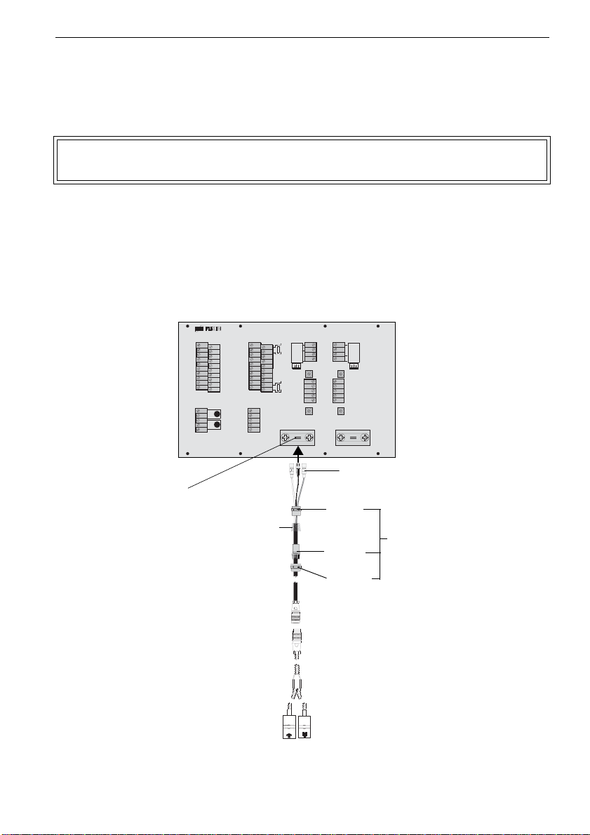
7 Installation of FLUXUS G709
T 1 A
T 1 B
P T 1 0 0
T 4 B
T 4 A
P T 1 0 0
B :A :
S A 3
S A 1
S A 2
S A 4
S B 3
S B 1
S B 2
S B 4
A V S
A V
A R S
A G N
A R
B V S
B V
B R S
B G N
B R
A C
2 3 0 V
1 0 0 . ..
D C
V O L T
L O W
4 A +
4 B -
4 2
4 3
4 1
L +
L -
N
L 1
P E
P 4 +
P 5 +
P 2 +
P 3 +
P 1 +
P 6 a
P 7 a
P 7 +
P 5 a
P 6 +
P 4 -
P 5 -
P 2 -
P 3 -
P 1 -
P 6 b
P 7 b
P 7 -
P 5 b
P 6 -
T 2 A
T 2 B
T 1 B
S 1
T 1 A
T 4 A
T 4 B
T 3 B
S 3
T 3 A
T 2 a
T 2 b
T 1 b
S 2
T 1 a
T 4 a
T 4 b
T 3 b
S 4
T 3 a
AMP-Quick and
SMB connectors
shield terminal
transducers:
•ATEX zone 2
•FM Div. 2
• without explosion protection
basic
part
compression part
cap nut
cable gland
outer shield
KL6 KL8
7.3 Connection of the Transducers - Connection System AS
• Open the cable gland of the extension cable (see Fig. 7.6).
• Push the basic part of the cable gland towards the AMP-Quick and SMB connectors,
the cap nut and the compression part in the other direction.
Note! Cap nut, compression part and basic part of the cable gland remain on
the cable.
• Push the extension cable through the shield terminal to terminal strip KL6 for measuring channel A and to terminal strip KL8 for measuring channel B (see Fig. 7.6).
• Pull the extension cable back until the brushed back outer shield is below the shield
terminal (see Fig. 7.6).
• Fix the extension cable and the outer shield to the shield terminal.
• Connect the AMP-Quick and the SMB connectors with the sockets of the flowmeter (see
Fig. 7.6 and Table 7.7).
Fig. 7.6: Transducers (ATEX zone 2, FM Div. 2, without explosion protection)
66 UMG70XV3-4EN 12.01.2009
- direct connection
Page 67

7 Installation of FLUXUS G709
T 1 A
T 1 B
P T 1 0 0
T 4 B
T 4 A
P T 1 0 0
B :A :
S A 3
S A 1
S A 2
S A 4
S B 3
S B 1
S B 2
S B 4
A V S
A V
A R S
A G N
A R
B V S
B V
B R S
B G N
B R
A C
2 3 0 V
1 0 0 . . .
D C
V O L T
L O W
4 A +
4 B -
4 2
4 3
4 1
L +
L -
N
L 1
P E
P 4 +
P 5 +
P 2 +
P 3 +
P 1 +
P 6 a
P 7 a
P 7 +
P 5 a
P 6 +
P 4 -
P 5 -
P 2 -
P 3 -
P 1 -
P 6 b
P 7 b
P 7 -
P 5 b
P 6 -
T 2 A
T 2 B
T 1 B
S 1
T 1 A
T 4 A
T 4 B
T 3 B
S 3
T 3 A
T 2 a
T 2 b
T 1 b
S 2
T 1 a
T 4 a
T 4 b
T 3 b
S 4
T 3 a
KL1 KL3 KL5 KL7
KL2 KL4
KL6 KL8
power supply
(KL2)
Table 7.7: Terminal assignment
terminal connection
measuring channel A measuring channel B
X6AV X8BV SMB connector (white or marked cable)
X6AR X8BR SMB connector (brown cable)
X5 X7 AMP-Quick connector
7.4 Connection of the Power Supply
Attention! A switch according to IEC 61010-1:2001 has to be provided in the
building installation which must be near the instrument, easily accessible for the user and marked as disconnection device of the instrument.
•
Connect the leads with the terminals of terminal strip KL2 (see
Fig. 7.7 and Table 7.8).
Fig. 7.7 : Connection of the power supply
Table 7.8: Terminal assignment (power supply)
terminal connection AC terminal connection DC
PE earth PE earth
N neutral L- -DC
L1 phase 100...240 V AC, 50/60 Hz L+ +DC
fuse 1 A, time-lag fuse 1.6 A, time-lag
UMG70XV3-4EN 12.01.2009 67
Page 68

7 Installation of FLUXUS G709
I1 active loop
Terminal:P1+,P1-
T 1 A
T 1 B
P T 1 0 0
T 4 B
T 4 A
P T 1 0 0
B :A :
S A 3
S A 1
S A 2
S A 4
S B 3
S B 1
S B 2
S B 4
A V S
A V
A R S
A G N
A R
B V S
B V
B R S
B G N
B R
A C
2 3 0 V
1 0 0 . . .
D C
V O L T
L O W
4 A +
4 B -
4 2
4 3
4 1
L +
L -
N
L 1
P E
P 4 +
P 5 +
P 2 +
P 3 +
P 1 +
P 6 a
P 7 a
P 7 +
P 5 a
P 6 +
P 4 -
P 5 -
P 2 -
P 3 -
P 1 -
P 6 b
P 7 b
P 7 -
P 5 b
P 6 -
T 2 A
T 2 B
T 1 B
S 1
T 1 A
T 4 A
T 4 B
T 3 B
S 3
T 3 A
T 2 a
T 2 b
T 1 b
S 2
T 1 a
T 4 a
T 4 b
T 3 b
S 4
T 3 a
KL1 KL3 KL5 KL7
KL2 KL4
KL6 KL8
outputs
(KL1)
+
-
mA
+-
+
-
mA
+-
7.5 Connection of the Outputs
Configure the outputs (see chapter 18). The terminals
to be used for the connection of the output are displayed at the end of the configuration dialog (here: P1+
and P1- for the active current loop).
• Connect the leads to the terminals of terminal strip KL1 as displayed (see Fig. 7.8 and Table 7.9).
• Close the flowmeter. Screw the cover on the housing.
Table 7.9: Circuits of the outputs
output FLUXUS terminal circuits
active
current loop
semi-active
current loop,
operated as
active current
loop
68 UMG70XV3-4EN 12.01.2009
Fig. 7.8: Connection of the outputs
Px+
(red)
R
LOAD
< 500
(black)
Px-
Px+
(red)
(black)
Px-
R
LOAD
< 50
Page 69
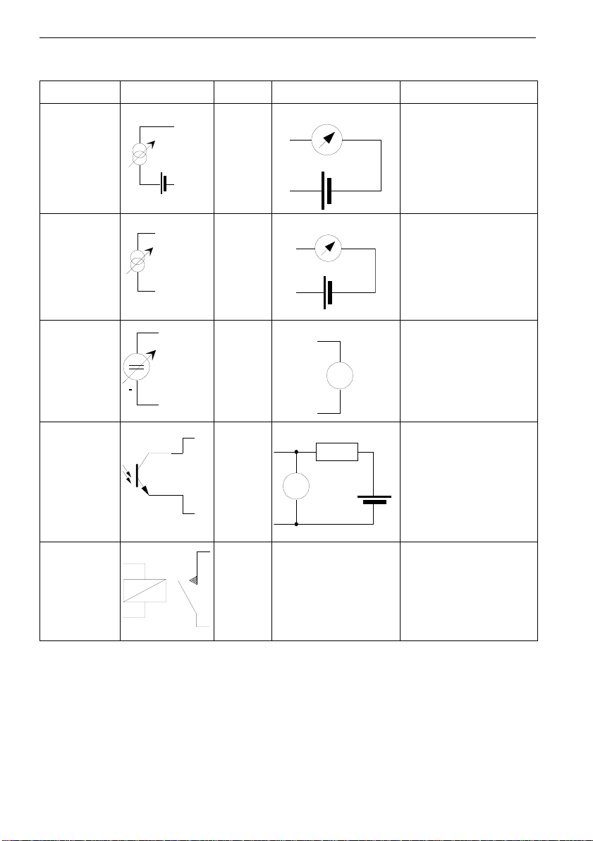
7 Installation of FLUXUS G709
+
-
mA
+-
+
-
U
H
mA
+-
+
-
U
H
+
Ri=500
Ri = 500
V
+
-
+
-
U
H
V
+
-
R
C
a
b
Table 7.9: Circuits of the outputs
output FLUXUS terminal circuits
semi-active
current loop,
Px+
(red)
operated as
passive current loop
(black)
Px-
U
= 0...24 V
H
> 0.021A . R
U
H
LOAD
[]
passive
current loop
Px+
(red)
= 5...25 V
U
H
>0.021A.R
U
H
= 12 V, R
If U
H
be in the range 0...380 .
(black)
Px-
voltage
output
Px+
(red)
(black)
R
> 2 M
LOAD
If R
LOAD
accuracy is lower than
specified.
Px-
binary output
(open
collector)
Px+
(red)
(black)
U
= 5...24 V
H
[k] = UH/Ic [mA]
R
C
I
= 1...4 mA
c
Px-
binary output
(Reed relay)
Px+
Pxa
U
I
MAX
MAX
= 24 V
= 150 mA
Pxb
Px-
R
is the sum of all ohmic resistances in the circuit (resistance of the conductors, inner resis-
LOAD
tance of the external power supply, resistance of the amperemeter/voltmeter, etc.)
LOAD
LOAD
is lower, the
[]+4V
must
UMG70XV3-4EN 12.01.2009 69
Page 70
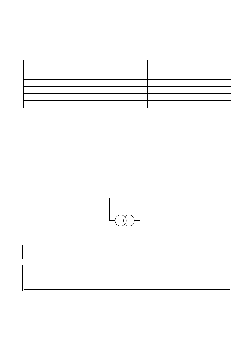
7 Installation of FLUXUS G709
+
-
Txb
TxA
7.6 Connection of the Inputs
Max. 4 temperature probes Pt100 (4-wire) can be connected to the flowmeter (option).
Configure the temperature inputs (see chapter 17).
Table 7.10: Terminal assignment of the flowmeter
terminal connection with
extension cable
Txa red red
TxA gray red/blue
Txb blue white/blue
TxB white white
Sx Pt100 shield Pt100 shield
x = 1...4
7.6.1 Connection of a Current Input
An active current source has to be connected to a passive current input. A passive current source can be connected directly to an active current input, or to a passive current
input via an external power supply.
Connection of a Passive Current Source
At full load (20 mA), a DC voltage of min. 13 V is available for the supply of a passive current source.
Terminal TxA is on the upper, Txb on the lower terminal row (x = 1...4).
connection without
extension cable
Fig. 7.9: Connection of an external passive current source
Attention! The terminals Txa and TxB must not be connected.
Attention! Observe the polarity to avoid damage of the current source. The cur-
rent input could be destroyed by a permanent shorting of both terminals.
70 UMG70XV3-4EN 12.01.2009
Page 71
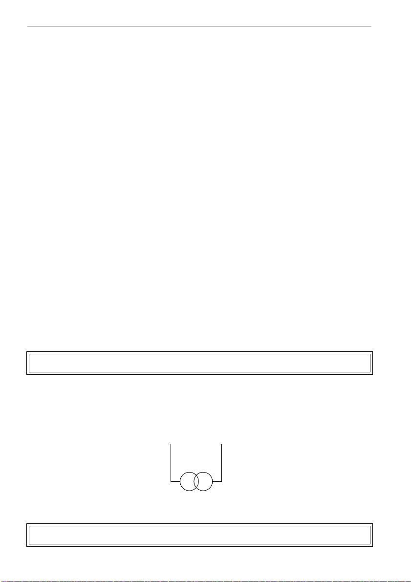
7 Installation of FLUXUS G709
-
+
TxB TxA
If the flowmeter has a passive current input, an external power supply is necessary. The
power supply U
must be able to
H
• supply sufficient power for the energy requirements of the passive current source
• cover the voltage drop over the measurement resistance (max. 1 V) and
• cover all other voltage drops (e.g. cable resistance) in the circuit.
A current of min. 20 mA has to be provided.
example: A passive current source (e.g. a pressure sensor) is connected to a passive
current input.
technical data of the pressure sensor:
auxiliary power supply: U
output signal: I
= 4...20 mA
A
= 11...30 V DC
S
The required auxiliary power supply of the pressure sensor will be calculated as follows:
U
H min
= U
R
R
+ I
S min
mea
cab
A max
- input impedance
- cable resistance)
· R
mea
+ I
A max
· R
cab
= 11 V + 20 mA · 50 + 20 mA · 2
= 12.04 V
U
H max
= 30 V (according to specification of the supplier)
Connection of an Active Current Source
Attention! Never connect an active current source to an active current input!
The terminals TxA and TxB are on the upper terminal row (x =1...4)
If the polarity of the current source is inversed, only the sign of the measured current will
change.
Fig. 7.10: Connection of an active current source
Attention! The terminals Txa and Txb must not be connected.
UMG70XV3-4EN 12.01.2009 71
Page 72

7 Installation of FLUXUS G709
T 1 A
T 1 B
P T 1 0 0
T 4 B
T 4 A
P T 1 0 0
B :A :
S A 3
S A 1
S A 2
S A 4
S B 3
S B 1
S B 2
S B 4
A V S
A V
A R S
A G N
A R
B V S
B V
B R S
B G N
B R
A C
2 3 0 V
1 0 0 . . .
D C
V O L T
L O W
4 A +
4 B -
4 2
4 3
4 1
L +
L -
N
L 1
P E
P 4 +
P 5 +
P 2 +
P 3 +
P 1 +
P 6 a
P 7 a
P 7 +
P 5 a
P 6 +
P 4 -
P 5 -
P 2 -
P 3 -
P 1 -
P 6 b
P 7 b
P 7 -
P 5 b
P 6 -
T 2 A
T 2 B
T 1 B
S 1
T 1 A
T 4 A
T 4 B
T 3 B
S 3
T 3 A
T 2 a
T 2 b
T 1 b
S 2
T 1 a
T 4 a
T 4 b
T 3 b
S 4
T 3 a
KL1 KL3 KL5 KL7
KL2 KL4
KL6 KL8
serial interface
RS485 (option)
(KL4)
Table 7.11: Technical data of the active current input
current input active passive
measuring range 0...20 mA -20...+20 mA
accuracy 0.1 % of reading 10 µA 0.1 % of reading 10 µA
input impedance 50 /0.6 W 50 /0.6 W
short circuit current 100 mA 100 mA
7.7 Connection of the Serial Interface
The RS232 interface is on the front plate of the flowmeter (see Fig. 4.4).
The flowmeter can be equipped with an RS485 interface (option). It will be connected as
follows:
Table 7.12: Terminal assignment
terminal connection
43 RS485 (shield)
4A+ RS485 A+
4B- RS485 B-
72 UMG70XV3-4EN 12.01.2009
Fig. 7.11: Connection of the serial interface
Page 73
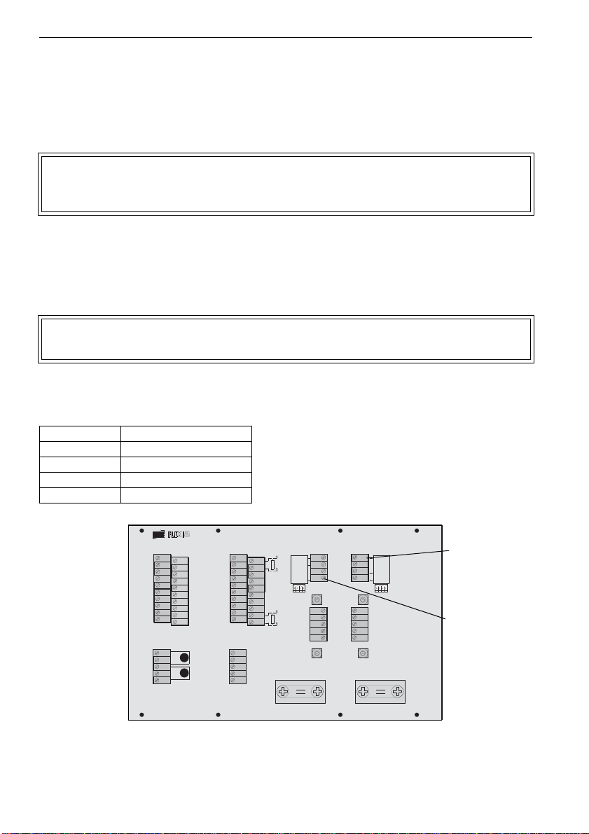
7 Installation of FLUXUS G709
T 1 A
T 1 B
P T 1 0 0
T 4 B
T 4 A
P T 1 0 0
B :A :
S A 3
S A 1
S A 2
S A 4
S B 3
S B 1
S B 2
S B 4
A V S
A V
A R S
A G N
A R
B V S
B V
B R S
B G N
B R
A C
2 3 0 V
1 0 0 . . .
D C
V O L T
L O W
4 A +
4 B -
4 2
4 3
4 1
L +
L -
N
L 1
P E
P 4 +
P 5 +
P 2 +
P 3 +
P 1 +
P 6 a
P 7 a
P 7 +
P 5 a
P 6 +
P 4 -
P 5 -
P 2 -
P 3 -
P 1 -
P 6 b
P 7 b
P 7 -
P 5 b
P 6 -
T 2 A
T 2 B
T 1 B
S 1
T 1 A
T 4 A
T 4 B
T 3 B
S 3
T 3 A
T 2 a
T 2 b
T 1 b
S 2
T 1 a
T 4 a
T 4 b
T 3 b
S 4
T 3 a
KL1 KL3 KL5 KL7
KL2 KL4
KL6 KL8
sensor module
measuring
channel A
(KL5)
sensor module
measuring
channel B
(KL7)
X5 X7
7.8 Connection of the Sensor Module (SENSPROM)
The sensor module contains important transducer data for the operation of the flowmeter
with the transducers. It is connected with the corresponding terminals of the flowmeter.
If transducers are replaced or added, the sensor module has to be replaced or added,
too.
Note! The serial number of sensor module and transducer have to be iden-
tical. A wrong or incorrectly connected sensor module will result in incorrect measured values or in measurement failure.
• Disconnect the power supply of the power supply.
• If the transducer cable has a 4-pole connector, connect it with socket X5 (terminal strip
KL5) or X7 (terminal strip KL7) (see Fig. 7.12).
• Otherwise, connect the sensor module with the terminals of terminal strip KL5 or KL7
(see Fig. 7.12).
Attention! The sensor module and the connector must not be connected at the
same time.
• If the cable with the 4-pole connector is cut, it can be connected directly to the terminal
strip KL5 or KL7 (see Fig. 7.12 and Table 7.13).
Table 7.13: Terminals for the connection of the sensor module
terminal connection
SA1 gray
SA2
SA3 brown
SA4 green
UMG70XV3-4EN 12.01.2009 73
Fig. 7.12: Connection of the sensor module (SENSPROM)
Page 74
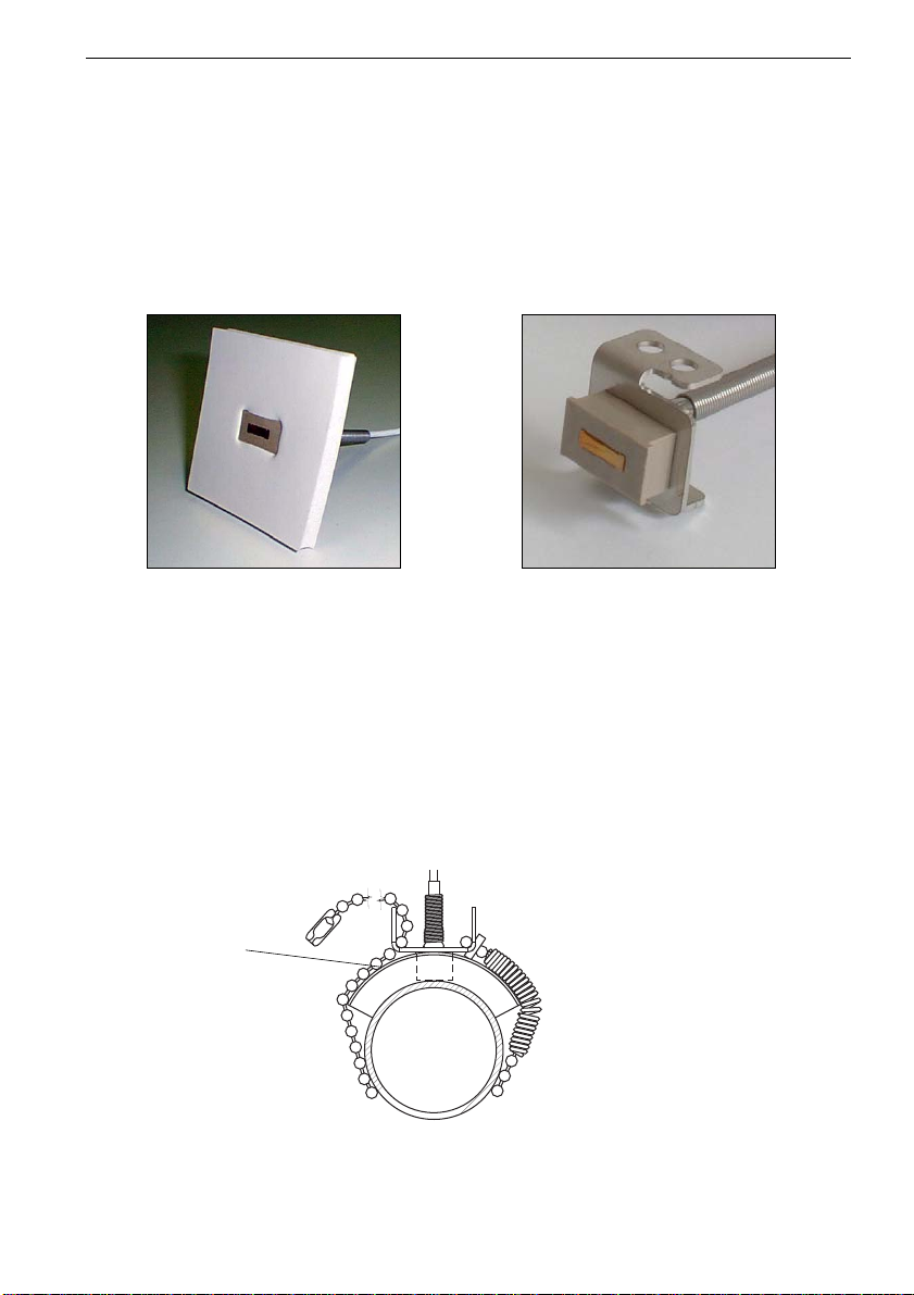
8 Installation of the Temperature Probe (Option)
a)
b)
slot at the upper
side of the
temperature probe
8 Installation of the Temperature Probe (Option)
8.1 Fixing of the Temperature Probe
• Remove rust, insulation material and loose paint to guarantee a good thermal contact.
• Clean the pipe.
• Mount the protection plate and the isolation foam to the temperature probe (see Fig.
8.1).
Fig. 8.1: Temperature probe:
a) with protection plate and isolation foam
b) without protection plate and isolation foam
- Apply a film of thermal conductivity paste (no FLEXIM supply) onto the contact surface of the temperature probe.
- Take the spring end of the ball chain and insert the last ball in one of the slots on the
top of the temperature probe.
- Place the chain around the pipe. Pull the chain firmly and insert it in the second slot
of the temperature probe (see Fig. 8.2).
74 UMG70XV3-4EN 12.01.2009
Fig. 8.2: Installed temperature probe
Page 75
8 Installation of the Temperature Probe (Option)
8.2 Connection of the Temperature Probe
• Connect the temperature probe with the temperature input of the flowmeter.
Tabelle 8.1: Terminal strip KL2 of the flowmeter
terminal connection of
temperature probe
T1a...T4a red red
T1A...T4A red/blue gray
T1b...T4b white/blue blue
T1B...T4B white white
S1...S4 shield shield
connection of
extension cable
UMG70XV3-4EN 12.01.2009 75
Page 76
9 Start-up
FLEXIM FLUXUS
G70X-XXXXXXXX
>PAR< mea opt sf
Parameter
>PAR< mea opt sf
Parameter
-
O
+
O
9.1 Switching on
9.2 Displays
9.2.1 Main Menu
9 Start-up
As soon as the flowmeter is connected with the power supply it will be displayed which transducer has been detected
at which channel.
Afterwards the serial number of the flowmeter will be displayed for a short time.
Data can not be entered while the serial number is displayed.
After initialization, the main menu is displayed in the selected language. The language of the display can be set
(see section 9.4).
The main menu contains the program branches:
• PAR (parameters)
• MEA (measuring)
• OPT (output options)
• SF (special functions)
The selected program branch is displayed in capital letters between arrows. The complete name of the selected program branch is displayed in the lower line.
Select a program branch with key and . Press ENTER.
Note! By pressing key BRK, the measurement will be stopped and the main
Note! In this manual, all program entries and keys are indicated in capital
76 UMG70XV3-4EN 12.01.2009
menu selected.
letters. Program entries are indicated in typewriter characters (PA-
RAMETER). The menu items will be separated from the main menu by
a backslash "\".
Page 77
9 Start-up
parameter
>PAR<
selection of the
measuring channel
pipe parameters
medium parameters
transducer type
extension cable
measuring
>MEA<
selection of the
measuring channel
measuring
point number
sound path
transducer
positioning
measurement
consistency check
output options
>OPT<
selection of the
measuring channel
physical quantity
unit of measurement
damping
measured value
output
special function
>SF<
system settings
1)
instrument
information
print measured
values
delete measured
values
program code
install material
install medium
9.2.2 The Program Branches and their Menu Items
• The pipe and medium parameters will be input in the program branch PARAMETER.
• The steps for the measurement will be processed in the program branch MEASURING.
• Physical quantity and unit of measurement as well as all parameters necessary for the
measured value output will be defined in the program branch OUTPUT OPTIONS.
• All functions that are not directly related with the measurement are in program branch
SPECIAL FUNCTION.
For an overview of the program branches see section 9.2.3. For a detailed overview of
the menu structure see annex B.
9.2.3 Overview of the Program Branches
1
The following menu items are in SYSTEM SETTINGS:
• dialogs/menus
• inputs
• measurement
• gas measurement
• outputs
•storing
• serial output
• miscellaneous
• set clock
•libraries
UMG70XV3-4EN 12.01.2009 77
Page 78
9 Start-up
Parameter
for Channel A:
ON
O
OFF
O
Lining
no >YES<
-
O
+
O
R1=FUNC<typ mode
Function: MAX
-
O
+
O
ON
O
OFF
O
9.2.4 Navigation
If a vertical arrow is displayed, the menu item contains a scroll list. The current list
item is displayed in the lower line.
Scroll with key and to select a list item in the lower line. Press ENTER.
In some menu items, there is a horizontal scroll list in the lower line. The selected list
item is displayed in capital letters between arrows.
Scroll with key and to select a list item in the
lower line. Press ENTER.
In some menu items, there is a horizontal scroll list in the upper line. The selected list
item is displayed in capital letters between arrows. The current value of the list item is
displayed in the lower line.
Scroll with key and to select a list item in the upper line.
Scroll with key and to select a value for the selected list item in the lower line.
Press ENTER.
9.3 HotCodes
A HotCode is a key sequence activating some settings:
• language selection (see section 9.4)
• switching on the SuperUser mode (see chapter 16)
• switching on the FastFood mode (see section 12.6)
• manual input of the lower limit for the inner pipe diameter (see section 12.8)
A HotCode can be entered in the main menu after pressing key C.
78 UMG70XV3-4EN 12.01.2009
Page 79

9 Start-up
FLEXIM FLUXUS
G70X-XXXXXXXX
9.4 Language Selection
The flowmeter can be operated in the languages listed below. The language can be selected with the following HotCodes:
Tabelle 9.1: Language HotCodes
909031 Dutch
909033 French
909034 Spanish
909044 English
909049 German
Depending on the technical data of the flowmeter, some of the languages might not be
implemented.
When the last digit is entered, the main menu will be displayed in the selected language.
The selected language remains activated after switching the flowmeter off and on again.
Hinweis! After initialization of the flowmeter the default language will be set
(key BRK and C when switching on).
9.5 Operation State Indication (G709)
The operation state is indicated by 2 LEDs.
Table 9.2: Operation state indication (LED SIGNAL)
LED off flowmeter offline
LED lights green signal quality of measuring channel sufficient for measurement
LED lights red signal quality of measuring channel sufficient for measurement
Table 9.3: Operation state indication (LED READY)
LED off no measurement
LED lights yellow measurement
LED flashes yellow before a HotCode can be entered, key C has to be pressed
9.6 Interruption of the Power Supply
All current measuring parameters will be stored in a non-volatile cold start resistant EPROM as soon as the measurement begins. The operation of the flowmeter will be interrupted if the power supply fails. All input data remain saved..
After return of the power supply, the serial number will be
displayed for a few seconds.
The stopped measurement will be continued. All selected output options are still active.
The measurement is not continued after return of the power supply if a cold start was
performed.
UMG70XV3-4EN 12.01.2009 79
Page 80

10 Basic Measurement
>PAR< mea opt sf
Parameter
Parameter
for Channel A:
Outer Diameter
100.0 mm
Outer Diameter
1100.0 MAXIMAL
10 Basic Measurement
The pipe and medium parameters will be entered for the selected measuring point (see
chapter 5). The ranges are limited by the properties of the transducers and of the flowmeter.
Note! The transducers have to be connected to the flowmeter during input
of the parameters.
Note! The parameters will be stored only if the program branch PARAME-
TER is finished completely once.
10.1 Input of the Pipe Parameters
Select the program branch PARAMETER. Press ENTER.
Select the channel for which parameters are to be entered. Press ENTER.
This display will not be indicated, if the flowmeter has
only one measuring channel.
10.1.1 Outer Pipe Diameter/Pipe Circumference
Enter the outer pipe diameter. Press ENTER.
It is possible to enter the pipe circumference instead of the outer pipe diameter (see section 15.2.1).
If the input of the pipe circumference has been activated and 0 (zero) is entered for the
OUTER DIAMETER, the menu item PIPE CIRCUMFER. will be displayed. If the pipe circumference is not to be entered, press key BRK to return to the main menu and start the
parameter input again.
80 UMG70XV3-4EN 12.01.2009
An error message will be displayed if the entered parameter is not within the range. The limit will be displayed.
example: upper limit 1100 mm for the connected transducers and for a pipe wall thickness of 50 mm.
Page 81

10 Basic Measurement
Wall Thickness
3.0 mm
Pipe Material
Carbon Steel
c-Material
3230.0 m/s
Lining
no >YES<
Lining
Bitumen
10.1.2 Pipe Wall Thickness
Enter the pipe wall thickness. The range depends on
the connected transducers. Press ENTER.
Note! The inner pipe diameter (= outer pipe diameter - 2x pipe wall thick-
ness) will be calculated internally. If the value is not within the inner
pipe diameter range of the connected transducers, an error message
will be displayed.
It is possible to change the lower limit of the inner pipe diameter for a
given transducer type (see section 12.8).
10.1.3 Pipe Material
The pipe material has to be selected to determine the sound velocity. The sound velocity
for the materials in the scroll list are stored in the flowmeter.
Select the pipe material from the scroll list.
If the material is not in the scroll list, select OTHER MA-
TERIAL. Press ENTER.
The materials to be displayed in the scroll list can be selected (see chapter 14.5).
When the pipe material is selected, the corresponding sound velocity is set automatically. If OTHER MATERIAL is selected, the sound velocity has to be entered.
Enter the sound velocity of the pipe material. Press ENTER.
Note! Enter the sound velocity of the material (i.e. longitudinal or transver-
sal velocity) which is nearer to 2500 m/s.
For the sound velocity of some materials see annex C, Table C.1.
10.1.4 Pipe Lining
If the pipe has an inner lining, select YES. Press EN-
TER.
If NO is selected, the next parameter will be displayed
(see section 10.1.5).
Select the lining material.
If the material is not in the scroll list, select OTHER MA-
TERIAL. Press ENTER.
The materials to be displayed in the scroll list can be selected (see chapter 14.5).
UMG70XV3-4EN 12.01.2009 81
Page 82
10 Basic Measurement
c-Material
3200.0 m/s
Liner Thickness
3.0 mm
Roughness
0.4 mm
Medium
natural gas
If OTHER MATERIAL is selected, the sound velocity has to be entered.
Enter the sound velocity of the lining material. Press
ENTER.
For the sound velocity of some materials see annex C, Table C.1.
Enter the thickness of the liner. Press ENTER.
Note! The inner pipe diameter (= outer pipe diameter - 2x pipe wall thick-
ness - 2x liner thickness) will be calculated internally. If the value is
not within the inner pipe diameter range of the connected transducers, an error message will be displayed.
It is possible to change the lower limit of the inner pipe diameter for a
given transducer type (see section 12.8).
10.1.5 Pipe Roughness
The flow profile of the medium is influenced by the roughness of the inner pipe wall. The
roughness will be used for the calculation of the profile correction factor. As, in most cases, the pipe roughness can not be exactly determined, it has to be estimated.
For the roughness of some materials see annex C, Table C.2. The values are based on
experience and measurements.
Enter the roughness of the selected pipe or liner material.
Change the value according to the condition of the inner
pipe wall. Press ENTER.
10.2 Input of the Medium Parameters
The media to be displayed in the scroll list can be selected (see chapter 14.5).
For the programmed parameters of common media see annex C, Table C.3.
If a medium is selected from the scroll list, the menu item for the input of the medium
temperature is displayed directly (see section 10.2.5).
If OTHER MEDIUM is selected or no data set for the selected medium is stored in the flowmeter (e.g. natural gas, as the parameters depend on the composition of the natural
gas), the medium parameters have to be entered first:
82 UMG70XV3-4EN 12.01.2009
Select the medium from the scroll list.
If the medium is not in the scroll list, select OTHER MA-
TERIAL. Press ENTER.
Page 83

10 Basic Measurement
c-Medium MIN
1400.0 m/s
kinem. Viscosity
1.00 mm2/s
Density
60.00 kg/m3
Gas compr.factor
1.000 factor
• min. and max. sound velocity
• kinematic viscosity
•density
• gas compressibility factor
10.2.1 Sound Velocity
The sound velocity of the medium is used for the calculation of the transducer distance at
the beginning of the measurement. However, the sound velocity does not influence the
measuring result directly. Often, the exact value of the sound velocity for a medium is unknown. A range of possible values for the sound velocity must therefore be entered.
These displays are indicated only if OTHER MEDIUM has been selected.
Enter the min. and max. sound velocity of the medium.
Press ENTER after each input.
10.2.2 Kinematic Viscosity
The kinematic viscosity influences the flow profile of the medium. The entered value and
other parameters will be used for the profile correction. This display is indicated only if
OTHER MEDIUM has been selected or no data set for the selected medium is stored in
the flowmeter (e.g. natural gas).
Enter the kinematic viscosity of the medium. Press ENTER.
10.2.3 Density
The mass flow will be calculated on the base of the density (product of volume flow and
density). This display is indicated only if OTHER MEDIUM has been selected or no data
set for the selected medium is stored in the flowmeter (e.g. natural gas).
Enter the operating density of the medium. Press ENTER.
10.2.4 Gas Compressibility Factor
The gas compressibility factor is needed for the calculation of the standard volume flow
(see section 11.1.1). Take care that the value is selected corresponding to the operating
pressure, the operating temperature and the composition of the gas. This display is indicated only if OTHER MEDIUM has been selected or no data set for the selected medium is
stored in the flowmeter (e.g. natural gas).
Enter the gas compressibility factor. Press ENTER.
UMG70XV3-4EN 12.01.2009 83
Page 84

10 Basic Measurement
Medium Temperat.
20.0 C
Fluid Pressure
60.00 bar
Transducer Type
Standard
Transd. Data 1
35.99
10.2.5 Medium Temperature
At the beginning of the measurement, the medium temperature is used for the interpolation of the sound velocity and thus, for the calculation of the recommended transducer
distance and for the interpolation of the gas compressibility factor.
During measurement, the medium temperature will be used for the interpolation of density and viscosity of the medium.
The value entered here will be used for the calculations if the medium temperature is not
measured and fed to an input of the flowmeter.
Enter the medium temperature. The value must be
within the operating temperature range of the transducers. Press ENTER.
10.2.6 Medium Pressure
The medium pressure will be used for the interpolation of the sound velocity and of the
gas compressibility factor. This display is indicated only if SPECIAL FUNCTIONS\SYS-
TEM SETTINGS\MEASURING\GAS-MEASURING has been activated or if GAS-MEASURING has been deactivated and SPECIAL FUNCTIONS\SYSTEM SETTINGS\DIALOGS/
MENUS\MEDIUM PRESSURE has been activated.
Enter the medium pressure. Press ENTER.
10.3 Other Parameters
10.3.1 Transducer Parameters
If transducers are detected at a measuring channel, input of parameters will be finished.
Press ENTER. The main menu will be displayed.
If no or special transducers are connected, the transducer parameters have to be entered.
Note! If standard transducer parameters are used, FLEXIM can not guaran-
84 UMG70XV3-4EN 12.01.2009
Select STANDARD to use the standard transducer parameters stored in the flowmeter.
Select SPECIAL VERSION to enter the transducer parameters. The parameters have to be provided by the
transducer manufacturer.
Press ENTER.
tee for the precision of the measured values. A measurement might
be even impossible.
If SPECIAL VERSION is selected, enter the 6 transducer parameters specified by the manufacturer. Press ENTER after each input.
Page 85
10 Basic Measurement
Additional cable
65.0 m
par >MEA< opt sf
Measuring
par >MEA< opt sf
NO DATA !
CHANN: >A< B Y Z
MEASUR - .
-
O
+
O
ON
O
Meas. Point No.:
1 ()
10.3.2 Extension Cable
If the transducer cable has to be extended, enter the
additional cable length (e.g. between the junction box
and the flowmeter). Press ENTER.
10.4 Selection of the Channels
The channels on which will be measured can be activated individually. This is only possible if the flowmeter has more than one measuring channel.
Select the program branch MEASURING. Press ENTER.
If this error message is displayed, the parameters are
not complete. Enter the missing parameters in the program branch PARAMETER.
The channels for the measurement can be activated
and deactivated.
This display will not be indicated, if the flowmeter has
only one measuring channel.
The symbols mean:
: the channel is active
–: the channel is not active
•: the channel can not be activated
Note! A channel can not be activated if the parameters are not valid, e.g. if
the parameters in the program branch PARAMETER of the channel
are not complete.
• Select a channel with key and .
• Press key to activate or deactivate the selected channel.
• Press ENTER.
A deactivated channel will be ignored during the measurement. Its parameters will remain unchanged.
If the data memory or the serial interface is activated, the measuring point number has to
be entered:
If arrows are displayed, ASCII text can be entered.
If digits are displayed, only digits, point and hyphen can
be entered.
Enter the measuring point number. Press ENTER.
UMG70XV3-4EN 12.01.2009 85
Page 86

10 Basic Measurement
A
!
A
A < 0
reflection mode, number of sound paths = 2
diagonal mode, number of sound paths = 3
diagonal mode, number of sound paths = 1, negative transducer distance
A: Sound Path
2NUM
10.5 Define Number of Sound Paths
The number of transits of the ultrasonic waves through the medium depends on the
placement of the transducers on the pipe.
If the number of transits is odd (diagonal mode), the transducers will be mounted on opposite sides of the pipe.
If the number of transits is even (reflection mode), the transducers will be mounted on the
same side of the pipe.
An increased number of transits means increased accuracy of the measurement. However, the increased transit distance results in a higher attenuation of the signal.
The reflections on the opposite pipe wall and deposits on the inner pipe wall cause additional amplitude losses of the sound signal.
If the signal is attenuated strongly by the medium, the pipe, deposits, etc., the number of
sound paths has to be set to 1 if necessary.
Note! Exact positioning of the transducers is easier for an even number (re-
86 UMG70XV3-4EN 12.01.2009
Fig. 10.1: Sound path and transducer distance (A)
flection mode) of transit paths than for an odd number (diagonal
mode).
A value for the number of sound paths corresponding to
the connected transducers and the entered parameters
will be recommended. Change the value if necessary.
Press ENTER.
Page 87
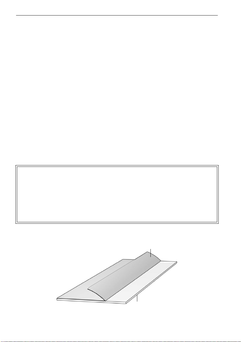
10 Basic Measurement
damping mat
protection sheet
10.6 Installation of the Damping Mats
Before the transducers are mounted, damping mats will be installed. The damping mats
reduce propagation of noise in the pipe wall.
• Select the measuring point according to the recommendations in chapter 5.
• Clean the pipe surface at the selected measuring point:
- Smooth a coat of paint by grinding. The paint does not need to be removed completely.
- Grind rust or loose paint.
- Remove grease or dust. Clean the pipe surface with soap sud.
• Select type and size of the damping mat (see annex A, sectionTechnical Data).
• Select the installation instructions corresponding to the supplied damping mat (see
section 10.6.1 or 10.6.2).
10.6.1 Installation of Self-Adhesive Damping Mats
Observe the operating temperature of the damping mat (see annex A, section Technical
Data).
• Cut the damping mat to size, if necessary (see annex A, section Technical Data).
• Remove a part of the protection sheet and fold it (see Fig. 10.2).
Attention! Wear protective gloves and protective goggles when mounting the
damping mats.
In case of contact with the eyes:
• rinse immediately with plenty of water and
• see an eye specialist.
In case of contact with the skin:
• wash immediately with plenty of water.
• Fix the part of the damping mat where the protection sheet is removed to the pipe.
Fig. 10.2: Protection sheet folded
UMG70XV3-4EN 12.01.2009 87
Page 88

10 Basic Measurement
transducer
damping mat
1
2
• Fix the damping mat to the pipe: remove the protection sheet bit by bit from the damping mat and attach the damping mat to the pipe at the same time.
Note! Air pockets must be avoided.
improvement of adhesion and removal of air pockets:
• Press the roll in the middle of the damping mat along the pipe axis (see 1 in Fig. 10.3).
• Press the roll from the middle to the sides (see 2 in Fig. 10.3).
• Cut the remaining air pockets by a knife.
Fig. 10.3: Installation of the damping mat (reflection mode)
Fig. 10.4: Installation of the damping mat (diagonal mode)
88 UMG70XV3-4EN 12.01.2009
Page 89

10 Basic Measurement
pipe damping mat
reflection point
Note! The damping mat adheres strongly to the pipe. Later alignment is not
possible. The damping mat has to be positioned correctly immediately.
Note! The damping mat can not be reused after removal.
• Depending on the transducer type, another layer of the damping mat is necessary (see
annex A, Technical Data). Repeat the steps for the installation of the damping mat.
• Mount the transducers onto the damping mat. Select the installation instruction corresponding to the supplied transducer mounting fixture (see section 10.7).
• If the measuring point is close to a reflection point (e.g. flange), a damping mat has to
be installed there, if necessary (see Fig. 10.5). Repeat the steps for the installation of
the damping mat.
Fig. 10.5: Installation of the damping mat to the reflection point
Note! Damping mats will be mounted to the complete circumference of the
pipe at the reflection point (see Fig. 10.5).
10.6.2 Installation of non Self-Adhesive Damping Mats
Observe the operating temperature of the damping mat (see annex A, section Technical
Data).
The non self-adhesive damping mats can be reused. They are not suitable for permanent
use.
A water based ultrasound gel will be used for coupling. The ultrasound gel can dry and is
then no longer effective.
UMG70XV3-4EN 12.01.2009 89
Page 90
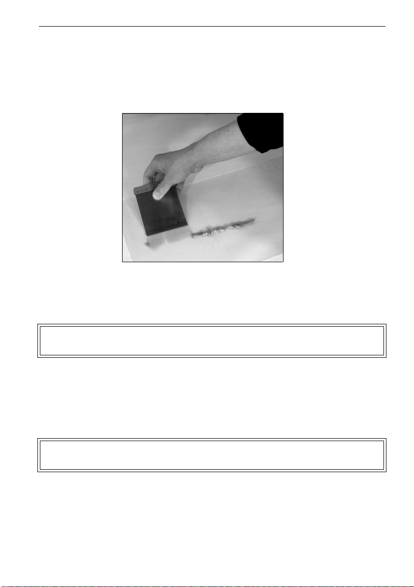
10 Basic Measurement
• Cut the damping mat to size, if necessary (see annex A, section Technical Data).
• Apply the a bead of ultrasound gel along the center line onto the inner side of the
damping mat.
• Spread the ultrasound gel evenly on the surface of the damping mat by means of a
spattle (see Fig. 10.6).
Fig. 10.6: Application of ultrasound gel to the damping mat
• Position the damping mat on the pipe (see Fig. 10.3).
• Remove air pockets by means of the supplied roller.
Note! When measuring in diagonal mode, a damping mat will be fixed addi-
tionally to the opposite side of the pipe (see Fig. 10.4).
• Mount the transducers onto the damping mat. Select the installation instruction corresponding to the supplied transducer mounting fixture (see section 10.7).
• If the measuring point is close to a reflection point (e.g. flange), a damping mat has to
be installed there, if necessary (see Fig. 10.5).
• Repeat the steps for the installation of the damping mat.
Note! Damping mats will be mounted to the complete circumference of the
pipe at the reflection point (see Fig. 10.5).
90 UMG70XV3-4EN 12.01.2009
Page 91

10 Basic Measurement
Transd. Distance
A:54 mm Reflec
10.7 Mounting and Positioning the Transducers
Observe the safety instructions in chapter 2.
The transducers will be fixed to the pipe by means of the supplied transducer mounting
fixture.
• Install the damping mats (see section ).10.6
• Use coupling foil (only if damping mats are not installed) or apply a bead of acoustic
coupling compound along the center line onto the contact surface of the transducers.
• Air pockets must not be between transducer contact surface, damping mat and pipe
wall.
• Make sure that the transducer mounting fixture applies the necessary pressure on the
transducers.
The transducer will be mounted so that the engravings on the transducers form an arrow
(see Fig. 10.7). The transducer cables show then in opposite directions. The arrow indicates the positive flow direction (see section 10.9).
Fig. 10.7: Correct positioning of the transducers
10.7.1 Transducer Distance
A value for the transducer distance is recommended.
Mount the transducers on the pipe adjusting this value
(see section 10.5). Press ENTER.
A - measuring channel
REFLEC - reflection mode
DIAGON - diagonal mode
The transducer distance given here is the distance between the inner edges of the transducers. A negative transducer distance is possible for a measurement in diagonal mode
on very small pipes (see Fig. 10.1).
Note! The accuracy of the recommended transducer distance depends on
the accuracy of the pipe and medium parameters entered.
UMG70XV3-4EN 12.01.2009 91
Page 92

10 Basic Measurement
1
2
1
2
10 Basic Measurement
10.7.2 Mounting the Transducers with Mounting Shoes and Tension
Straps
Mounting the Transducers with Clasps
• Cut the tension straps (pipe circumference + 120 mm).
• Make sure that part (2) of the clasp is on top of part (1) (see Fig. 10.8). The hooks of
part (2) must be on the outer side of the clasp.
• Pull approx. 2 cm of the tension strap through the slot of the clasp (see Fig. 10.9) to fix
the clasp to the tension strap.
• Bend the end of the tension strap back. Push the other end of the tension strap through
the groove on the top of the mounting shoe.
• Place the clasp on the side of the pipe. Turn the tension strap around the pipe (see Fig.
10.10).
Note! The clasp must be in contact completely with the pipe to ensure a
good fixation.
• Place the mounting shoe on the pipe. Hold clasp and mounting shoe with one hand
while pushing the tension strap through parts (2) and (1) of the clasp (see Fig. 10.8).
• Pull the tension strap firmly and engage it in the inner hooks of the clasp.
Fig. 10.8: Clasp
Fig. 10.9: Clasp with tension strap
Note! At pipes with large diameters, use tongs, if necessary, to tense the
tension strap.
92 UMG70XV3-4EN 12.01.2009
Page 93
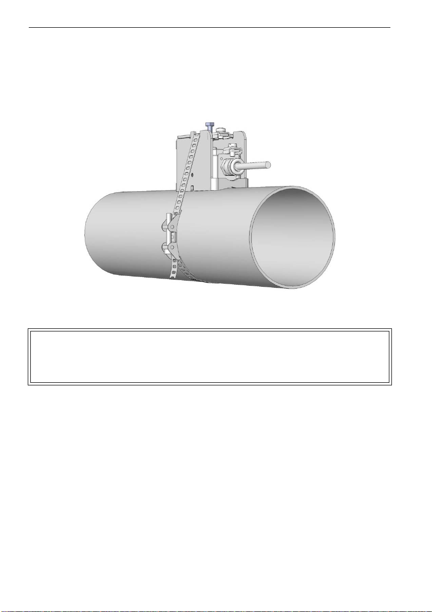
10 Basic Measurement
• Mount the second transducer in the same way. Adjust the displayed transducer distance by means of the measuring tape.
• Tighten the screws of the clasps.
• Push the transducers in the mounting shoes. Press the transducer firmly on the pipe.
There should be no air pockets between transducer surface and pipe wall. Tighten the
screw of the mounting shoe firmly.
Fig. 10.10: Mounted transducer in mounting shoe, fixed by clasp
Note! When the transducers are mounted on a vertical pipe and the flow-
meter is placed lower than the pipe, the cable of the upper transducer
should be fixed to the tension strap by a cable tie to protect the cable
from mechanical strain.
UMG70XV3-4EN 12.01.2009 93
Page 94
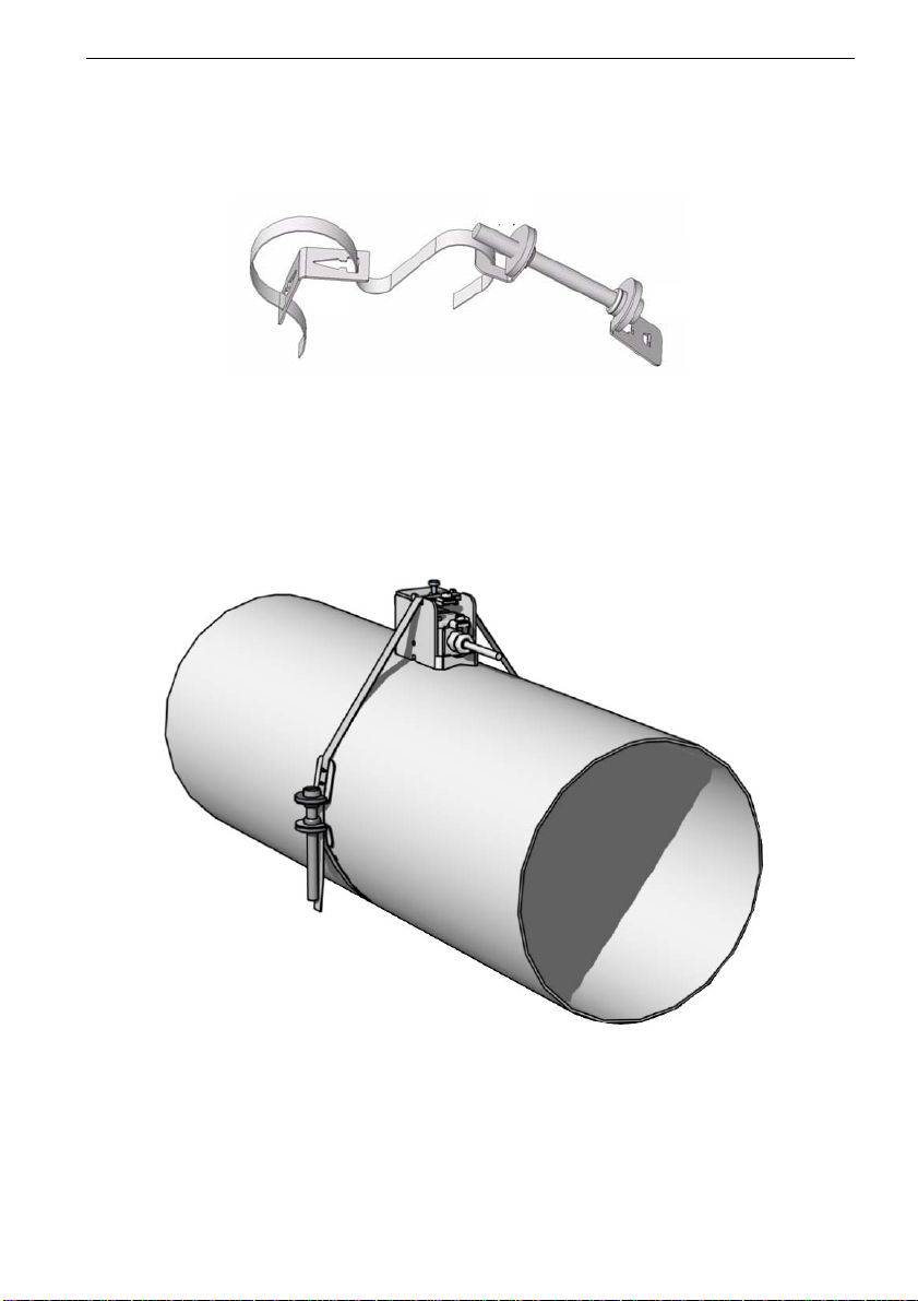
10 Basic Measurement
1
2
3
Mounting the Transducers with FLEXIM Clasps
• Cut the tension straps (pipe circumference + 120 mm).
• Push approx. 2 cm of the tension strap through the slot of the clasp (see Fig. 10.11).
Fig. 10.11: Clasp, metal spring with tension strap
• Push the tension strap through the metal spring (3, see Fig. 10.11).
• Bend the end of the tension strap back. Push the other end of the tension strap through
the groove on the top of the mounting shoe.
Place the clasp on the side of the pipe. Turn the tension strap around the pipe (see Fig.
10.12)
Fig. 10.12: Mounted transducer in mounting shoe, fixed with FLEXIM clasp
94 UMG70XV3-4EN 12.01.2009
Page 95
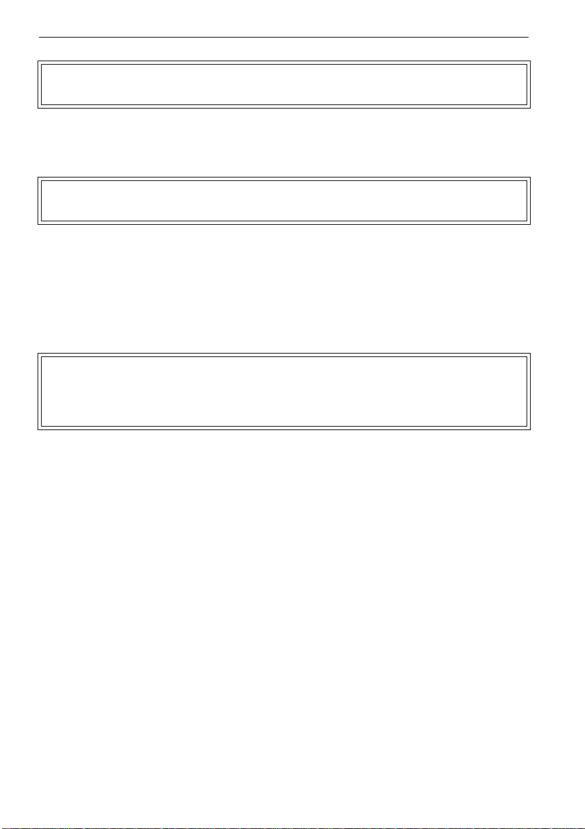
10 Basic Measurement
Note! The clasp and the metal spring must be in contact completely with
the pipe to ensure a good fixation.
• Place the mounting shoe on the pipe. Hold clasp and mounting shoe with one hand
while pushing the tension strap through parts (2) and (1) of the clasp (see Fig. 10.11).
• Pull the tension strap firmly and engage it in the inner hooks of the clasp.
Note! At pipes with large diameters, use tongs, if necessary, to tense the
tension strap.
• Mount the second transducer in the same way. Adjust the displayed transducer distance by means of the measuring tape.
• Tighten the screws of the clasps.
• Push the transducers in the mounting shoes. Press the transducer firmly on the pipe.
There should be no air pockets between transducer surface and pipe wall. Tighten the
screw of the mounting shoe firmly.
Note! When the transducers are mounted on a vertical pipe and the flow-
meter is placed lower than the pipe, the cable of the upper transducer
should be fixed to the tension strap by a cable tie to protect the cable
from mechanical strain.
UMG70XV3-4EN 12.01.2009 95
Page 96
10.7.3 Fine Adjustment of the Transducer Distance
Transd. Distance
A: 54 mm !
S=
A:<>=54 mm!
S=
Q=
trans. 94.0 s
Q=
DISP
DISP
Transd.Distance?
53.9 mm
10 Basic Measurement
If the displayed transducer distance is adjusted, press ENTER.
The positioning procedure is started.
A bar graph S= displays the amplitude of the received sig-
nal.
If the LED of the measuring channel lights green, the signal is sufficient for a measurement (only FLUXUS G709).
If the LED of the measuring channel lights red, the signal is
not sufficient for a measurement (only FLUXUS G709).
Shift a transducer slightly in the range of the recommended transducer distance
• FLUXUS G704: until the bar graph has max. length
(max. 6 squares)
• FLUXUS G709: until the LED of the measuring channel
lights green.
The following can be displayed in the upper line with key
and in the lower line with key :
• transducer distance
• C (signal noise ratio)
If min. one box is displayed, the signal is sufficient for
the measurement. Optimum for the measurement are
three or more boxes.
• bar graph Q= (signal quality), must have max. length
• transit time TRANS. in µs
• bar graph S= (signal amplitude)
If the signal is not sufficient for measurement, Q= UNDEF
will be displayed.
10 Basic Measurement
In case of larger deviations, check if the entered parameters are correct or repeat the
measurement at a different location on the pipe.
Repeat the steps for all channels on which will be measured. The measurement will be
started automatically afterwards.
96 UMG70XV3-4EN 12.01.2009
After the precise positioning of the transducers, the recommended transducer distance is displayed again.
Enter the actual (precise) transducer distance. Press ENTER.
Page 97
10 Basic Measurement
DISP
L=(50.0) 54.0 mm
54.5 m3/h
10.7.4 Consistency Check
If a wide range for the sound speed has been entered in the program branch PARAMETER
or the exact parameters of the medium are not known, a consistency check is recommended.
The transducer distance can be displayed during measurement by scrolling with key .
The optimum transducer distance (here: 50.0 mm) will be
displayed in parentheses in the upper line, followed by the
entered transducer distance (here: 54.0 mm). The latter
value must correspond to the actually adjusted transducer
distance. Press ENTER to optimize the transducer distance.
The optimum transducer distance is calculated on the basis of the measured sound
speed. It is therefore a better approximation than the first value which had been calculated on the basis of the approximate sound speed range entered in the program branch
PARAMETER.
If the difference of optimum and entered transducer distance is less than specified in Table 10.1 or Table 10.2, the measurement is consistent and the measured values are valid. The measurement can be continued.
If the difference is greater, adjust the transducer distance to the displayed optimum value. Afterwards, check the signal quality and the signal amplitude bar graph (see section
10.7.3). Press ENTER.
Table 10.1: Standard values for signal optimization of shear wave transducers
transducer frequency difference between optimum and entered transducer distance [mm]
P8
M10
K15
G20
Table 10.2: Standard values for signal optimization of Lamb wave transducers
transducer frequency difference between optimum and entered transducer distance [mm]
Q -3...+5
P- 6...+10
M -10...+20
K -25...+40
H - 35...+60
G -50...+100
UMG70XV3-4EN 12.01.2009 97
Page 98
10 Basic Measurement
Transd.Distance?
50.0 mm
L=(51.1) 50.0 mm
54.5 m3/h
DISP
DISP
A:Volume(oper.)
31.82 m3/h
A:Volume(norm.)
31.82 m3/h
DISP
A:Volume(oper.)
* 16.22 m3/h
Enter the new adjusted transducer distance. Press ENTER.
Scroll with key again until the transducer distance is
displayed and check the difference between optimum and
entered transducer distance. Repeat the steps if necessary.
Note! Never change the transducer distance during measurement without
having restarted the consistency check.
Repeat the steps for all channels on which will be measured.
10.7.5 Value of the Sound Speed
The sound velocity of the medium can be displayed during measurement by pressing key
.
If an approximate range for the sound speed has been entered in the program branch
PARAMETER and the transducer distance has been optimized afterwards as described in
section 10.7.4, it is recommended to note the sound velocity for the next measurement.
The optimization procedure does not need to be repeated then.
Also note the medium temperature as the sound speed depends on the temperature. The
value can be entered in the program branch PARAMETER or a user defined medium can
be defined for this sound velocity (see section 14.2 and 14.3).
10.8 Start of Measurement
If the standard volume flow is selected as physical quantity during the gas measurement,
the operating volume flow can be displayed, too.
If more than one measuring channel is available/activated, the flowmeter works with an
integrated measuring point multiplexer providing quasi simultaneous measurement on
the different measuring channels.
The flow is measured on one measuring channel for approx. 1 s, then the multiplexer
switches to the next activated channel.
98 UMG70XV3-4EN 12.01.2009
The measured values will be displayed in the lower line.
Press ENTER to return to the fine adjustment of the transducer distance (see section 10.7.3).
Press key to display the standard volume flow.
The character * indicates that the displayed value (here:
operational volume flow) is not the selected physical quantity (here: standard volume flow).
Page 99
10 Basic Measurement
The measuring time depends on the measuring conditions. If, e.g. the measuring signal
can not be detected immediately, the measurement might be > 1 s.
The outputs and the serial interface continuously get the measuring results of the assigned channel. The results will be displayed according to the actually selected output
options (see chapter 11). The default unit of measurement of the volume flow is m
3
/h. For
the selection of the values to be displayed and for setting of the output options see chapter 11. For further measuring functions see chapter 12.
10.9 Detection of Flow Direction
The flow direction in the pipe can be detected with the help of the displayed volume flow
in conjunction with the arrow on the transducers:
• The medium flows in arrow direction if the displayed volume flow is positive (e.g.
• The medium flows against the arrow direction if the displayed volume flow is negative
3
54.5 m
/h).
(e.g. -54.5 m
3
/h).
10.10 Stopping the Measurement
The measurement can be interrupted at any time by pressing key BRK, if not being protected by a program code (see section 12.9).
Note! Be careful not to interrupt a current measurement by inadvertently
pressing key BRK!
UMG70XV3-4EN 12.01.2009 99
Page 100
11 Displaying the Measured Values
par mea >OPT< sf
Output Options
Output Options
for Channel A:
Physic. Quant.
Volume(oper.)
Volume in
m3/h
11 Displaying the Measured Values
The physical quantity will be set in the program branch OUTPUT OPTIONS (see section
11.1).
During measurement, the designation of the physical quantity will be displayed in the upper line, its value in the lower line. The display can be adapted (see section 11.3).
11.1 Selection of the Physical Quantity and of the Unit of
Measurement
The following quantities can be measured:
• sound velocity
• flow velocity: is calculated on the basis of the measured transit time difference
• operating volume flow: will be calculated by multiplying the flow velocity by the cross-
section of the pipe
• standa rd volume flow: will be calculated on the basis of the operating volume flow
(see section 11.1.1)
• mass flow: will be calculated by multiplying the volume flow by the operating density of
the medium
The physical quantity will be selected as follows:
Select the program branch OUTPUT OPTIONS. Press EN-
TER.
Return to the main menu by pressing key BRK. The further menu items of the program
branch OUTPUT OPTIONS are for the activation of the measured value output.
Note! If the physical quantity or the unit of measurement is changed, the
100 UMG70XV3-4EN 12.01.2009
Select the channel for which the physical quantity is to be
entered. Press ENTER.
This display will not be indicated, if the flowmeter has only
one measuring channel.
Select the physical quantity in the scroll list. Press ENTER.
For the selected physical quantity (except for the sound
velocity), a scroll list with the available units of measurement is displayed. The previously selected unit of measurement is displayed first.
Select the unit of measurement for the selected physical
quantity. Press ENTER.
settings of the outputs have to be checked (see section 18).
 Loading...