

Flexiheat Compact ePlus6, Compact ePlus24, Compact ePlus9, Compact ePlus12, Compact ePlus18 Instructions For Installation, Handling Operation And Maintenance
Page 1
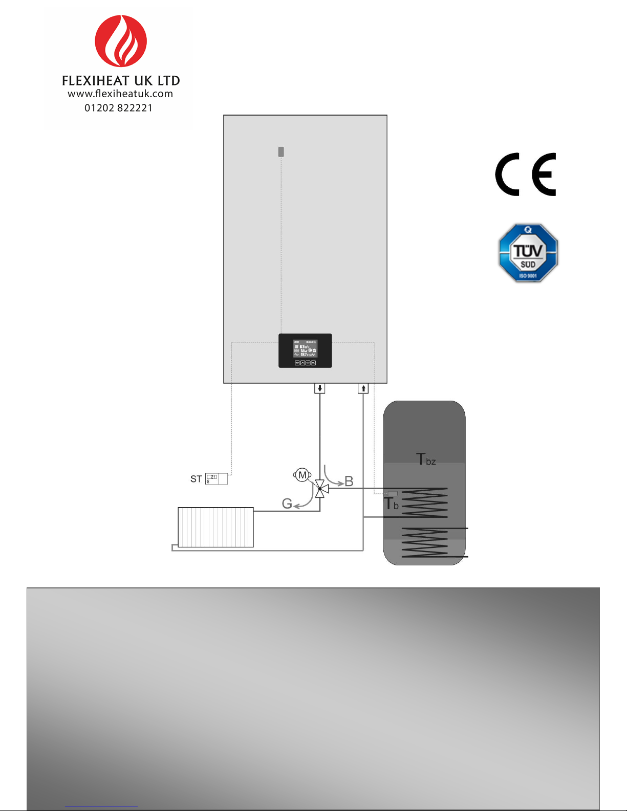
Instructions for installation, handling operation and maintenance – ENG
Compact ePlus
Electric boiler for heating and preparation of sanitary water with processor handling control
Page 2

CONTENT
Content
1. Explanation of symbols
2. Device data
2.1. Overview of types
2.2.1 Declaration of Conformity
2.2.2 Proper use
2.3 Installation instructions
2.4 Instructions for operation
2.5 Use of chemicals
2.6 Norms, regulations and standards
2.7 Tools, materials and auxiliary means
2.8 Minimum spacing and hazardous means
2.9 Product description
2.11 Scope of delivery
2.12 Type panel
2.13 Dimensions and technical data
3. Transport
4. Installing
4.1 Caution when installing
4.2 Distance
4.3 Disassembly of the front cover
4.4 Installation of the boiler
4.5 Introduction of hydraulic connectors
4.6 Filling and checking the installation
4.6.1 Filling the boiler with water and testing
4.6.2 Air discharging of the pump and unblocking
4.6.3 Discharge air from the boiler and installation
5. Electrical connector
5.1 Position of the entry for the introduction of the cable
5.2 Connecting the cable
5.3 Connection scheme
5.4 Power cable connection scheme
5.5 External control of the boiler (room thermostat)
6. Putting into operation
6.1 Before putting into operation
6.2 First putting into operation
6.3 Record on putting into operation
7. Handling operation of the heating regime and the preparation of sanitary water of heating
7.1 Instructions for operation
7.2 Overview of the setting elements
7.2.1 Functions of device
7.2.2 Basic settings
7.2.3 Heating regime
7.2.4 Symbols on the display
7.2.5 Symbols and warning codes
7.2.6 Symbols and error codes
7.3 Heating regulation
7.3.1 Regulator of room temperature
7.3.2 Cease of heating
7.4 Putting the boiler out of operation
7.5 Sanitary water preparation regime
7.6 Regime of heating and preparation of sanitary water
8. Cleaning and maintenance
9. Environmental protection and disposal into waste
10. Faults and their remedy
11. Instructions for designing
Page 3

Explanation of symbols and instructions for safe work
1.
Explanation of symbols and instructions for safe work
1.1 Explanation of symbols
1.2 Instructions for safe work
Instructions and warnings
Warnings are marked with a gray triangle in
the text, and are framed.
The risk of electric shock is indicated by the symbol
of lightning in the triangle, and framed.
Signal words at the beginning of the safety note indicate the
manner and severity of the consequences that threaten
unless there are applied measures to prevent danger.
•
NOTE means that minor material damages may
occur.
•
CAUTION
means that minor or medium-sized injuries
may occur.
•
WARNING
means that serious injuries can occur.
•
DANGER
means that serious injuries can occur.
Important information
Important information, which does not pose a
danger to people or things, is indicated by the
symbol shown in the text below.
They are limited by lines, above and below the text.
Other symbols
Table 1
General safety instructions
Failure to follow the safety instructions can result in serious
injuries - as well as to deadly consequences, material
damages and damage to the environment.
Provide a professional examination of the electrical
installation before installing the device.
All electrical operations must be carried out by a person
authorized to carry out electrical operations, according to
the relevant regulations.
Ensure that putting into operation, as well as
maintenance and repairs are carried out by an
authorized service centre.
Provide technical reception of the installation in
accordance with the relevant regulations.
Danger due to not respecting one's own safety in case of
an emergency, eg. in the event of fire.
Never expose yourself to life threatening situations.
Your
own safety is always a priority
.
Damage caused by wrong handling
Handling errors can lead to injury of persons and/or damage
to the installation.
Make sure that only people who know how to handle
properly the device have access to it.
Installation and putting into operation, as well as
maintenance and repair, must only be carried out
by an authorized service centre with appropriate
authorization for electrical works.
Installation and putting into operation
Leave the installation of the device only to an
authorized service centre.
Always start the boiler only if the installation is at an
appropriate pressure and the operating pressure is correct.
Do
not close the safety valves in any case in order to avoid
damage caused by too high pressure.
During heating,
the water can leak on the safety valve of the hot water
circuit and hot water pipe.
Install the device only in a room where freezing cannot
occur.
Do not store flammable materials or liquids near the
device.
Keep a safe distance according to applicable regulations.
Symbol
Meaning
Step of the action
Guidance to other places in the document or to other
documents.
•
Listing/Entry from the list
–
Listing/Entry from the list (2.)
Page 4

Explanation of symbols and instructions for safe work
Life-threathening danger from electric shock
Leave the introduction of electrical connection to an
authorized service technician. Follow the connection
scheme.
Before all works: disconnect the electric power supply.
Secure youself from accidental turning on.
Do not install this device in wet rooms.
Inspection / maintenance
Recommendation for the user: Make a maintenance
contract with an authorized service centre, that will
perform annual maintenance and control checks.
The user is responsible for the safety and
environmental acceptability of the installation.
Follow the safety instructions for safe work which are to b
found in the chapter
‘Cleaning and maintenance’
.
Original spare parts
No liability can be claimed for damages arising because of
the spare parts which are not supplied by the manufacturer.
Use only original spare parts.
Material damages from freezing
In the event of a risk of freezing, drain the water from the
boiler, tank and pipes of the heating system.
The risk of
freezing does not exist only when the entire installation
is dry.
Instructions for service technicians/centres
Inform the users about the operating mode of the device and
maintenance.
Inform the users that they must not make any changes
or repairs on their own.
Warn the users that children without adult supervision
should not be kept near the heating installation.
Fill in and submit the “Putting into operation” and
“Take-over Minutes” contained in this document.
Hand over the technical documentation to the user.
Disposal into waste
Dispose of packaging in an environmentally acceptable
manner.
Dispose of the device in an environmentally acceptable
manner at an authorized place.
Cleaning
Clean the device with a damp cloth from the outside.
Page 5
Device data
2.
Device data
These instructions contain important information on safe and
professional installation, putting into operation and
maintenance of the boiler.
These instructions are intended for installers who, on the
basis of their expertise and experience, have knowledge in
working with heating installations.
2.4 Instructions for operation
When working with the heating installation, observe the
following instructions:
The boiler should work in the working area up to a maximum
temperature of 80 °C, a minimum pressure of 0.8 bar and a
maximum pressure of 2.2 bar, and should be monitored regularly.
2.1 Overview of types
These instructions apply to the following types:
Compact ePlus
6-24k
W
2.2.1 Declaration of Conformity
We declare that the devices have been tested in
accordance with Directives 2006/95/EC (Low Voltage
Directive, LVD) and 2004/108/EC (Electromagnetic
Compatibility Directive, EMC).
2.2.2 Proper use
The boiler can only be used for heating the heating water and
for the indirect preparation of hot water. In order to ensure
proper use, it is necessary to comply with operating
instructions, data on the factory tile and technical data.
The boiler should only be handled by adults who are familiar
with the instructions and the work of the boiler.
Do not close the safety valve.
Inflammable objects must not be placed on or near
the boiler (within the safety distance).
Clean the surface of the boiler only with non-combustible
materials and agents.
Do not keep inflammable things in the room intended for
installation of the boiler (eg. petroleum, oil).
No cover must be opened during operation.
Keep a safe distance according to the local valid
regulations.
2.3 Installation instructions
2.5
Anti-freezing agents and inhibitors
Use only original spare parts of the manufacturer or
spare parts approved by the manufacturer.
No
liability is assumed for damages arising because
of the spare parts that are not supplied by the
manufacturer.
When installing a heating installation, follow the
following instructions:
•
valid construction regulations
• regulations and norms on the safety and technical
equipment of the heating installation
It is not allowed to use anti-freezing agents or inhibitors.
If
the use of the anti-freezing agent cannot be avoided, there
should be used anti-freezing products that are permitted for
heating installations.
Use of anti-freezing agents
:
shortens the lifetime of the boiler and
its parts
reduces the transfer of heat
• changes at the place of installation in accordance
with applicable regulations
Page 6

Device data
2.6 Norms,
regulations and standards
2.7 Tools, materi
als and auxiliary means
The product is in compliance with the following norms and
regulations:
Fo
r installation and maintenance of the boiler, standard tools
•
EN
50110-1:2003
–
handling and operation with
electrical installations
•
EN
55014:2001
– electromagnetic compatibility
conditions for household devices, electrical devices and
similar devices
•
EN 60
335-1+ed.2:2003
- electrical household
devices
•
EN 60
335-1+ed.2 zm.A
1:2005
- electrical household
devices
•
EN
61000-3-2 ed
.3:2006
- electromagnetic compatibility
(EMC)
– the limit for the harmonic current emission
•
EN
61000-3-3:1997
- electromagnetic compatibility (EMC
)
–
Law on the limitation of voltage fluctuations and
flickering of the low-voltage partition network
Certificates provided by accredited laboratory no.:
LVD standards : 08131402 i.no: I-005 10.01.2014
EMC standards : 071375680 i.no: I-005 10.01.2014
from the field of heating, plumbing and electrical installations
are required.
Page 7
Device data
2.8 Minimum spacing and
flammability of construction
materials
2.9 Product description
The basic components of the boiler are
:
Depending on the applicable regulations, other minimum
distances, other than those mentioned below, may be valued.
Follow the regulations on electrical installations and the
minimum distances in force in the countries concerned.
The minimum distance for heavily flammable and
self-extinguishing materials is 200 mm.
Flammability of component elements
A
non-flammable
A
1:
non-flammable
Asbestos, stone, ceramic wall tiles,
baked clay, mortar, (without organic
additives)
A
2:
with a small
amount of
inflammable
additional
elements (organic
components)
Panels made of plasterboard,
panels made of basac felt,
glass fibres,
panels made of
ACUMIN,
ISOMIN; RAJOIT,
LOGNOS, VELOX
and
HERACLI
T
B
flammable
B
1:
hardly
inflammable
Beech,
oak, veneered wood,
felt,
panels made of HOBREX,
VERZALIT i
UMAKART
B
2:
normally
flammable
Pine, larch and spruce, veneered
wood
B3:flammable
Asphalt, cardboard, cellulosic
materials, waterproofing tape, panels
of chipboard, cork, polyurethane,
polystyrene, polyethylene, floor
fibrous materials
Table 3 Flammability of component elements according to DIN
4102
•
Container of the boiler
with associated components
•
Frame of the device and the shell of the boiler
•
Control unit
•
Pum
p
•
Expansion container (according to capacity)
• Processor board and electronics of the
boiler
•
Water pressure sensor
•
Safety valve
The boiler can be installed as an integral part of the central
heating system, floor heating, and hybrid or accumulation
systems.
The boiler consists of a welded housing made of steel sheet with
thermal insulation. The boiler is fixed to the wall by using a frame and
the delivered installation kit.
Built-in thermal insulation in the shell
of the boiler reduces loss of heat.
At the same time, the
insulation also protects against noise.
The safety elements (valve for discharging of air, fuse of the
control surface, safety temperature limiter) are located at the
top of the boiler.
Depending on the type of boiler, electric heaters of different
power are used. The power of the boiler can be precisely
adjusted. The setting of different levels of power of the
boiler is done by using the buttons on the dashboard. The
number of levels of power is given in the table
(chapter
2.13.2
)
Page 8

Device data
1 UL
return
line of the boiler
2 IZ
starting line of the
boiler
3
Exchanger of the boiler
4
Electric heaters
5
Exspansion container
6
Pump
7
Valve for discharging of air (on the
pump)
8
Power line for the pump
9
Drainage tap
10
Automatic air discharger
11
Automatic fuses
12
Clamp for thermostat
13
Network board
14
Relays of electric heaters
15
Clamps of electric heaters
16
Strain relief connector for electric cable
17
Control panel with display
Page 9
Device data
2.10 Waste disposal
Dispose of packaging in an environmentally acceptable manner.
Take care that the components are replaced in an
environmentally acceptable manner.
2.11 Content of packaging
When delivering the boiler, comply with the following:
Make sure that the packaging is undamaged on
delivery.
Check whether the delivery is complete.
Part
number of pieces
Boiler
Compact ePlus
1
Installation kit
1
Manual
1
2.12 Factory tile
The factory tile is located on the outside of the boiler and contains the following technical data:
•
type of boiler
•
serial number/catalog
number
•
power
•
input power
•
maximum temperature
•
work pressure
•
volume of boiler’s container
•
mas
s
•
electric power supply
•
level of
protection
• manufacturer
Page 10
Device data
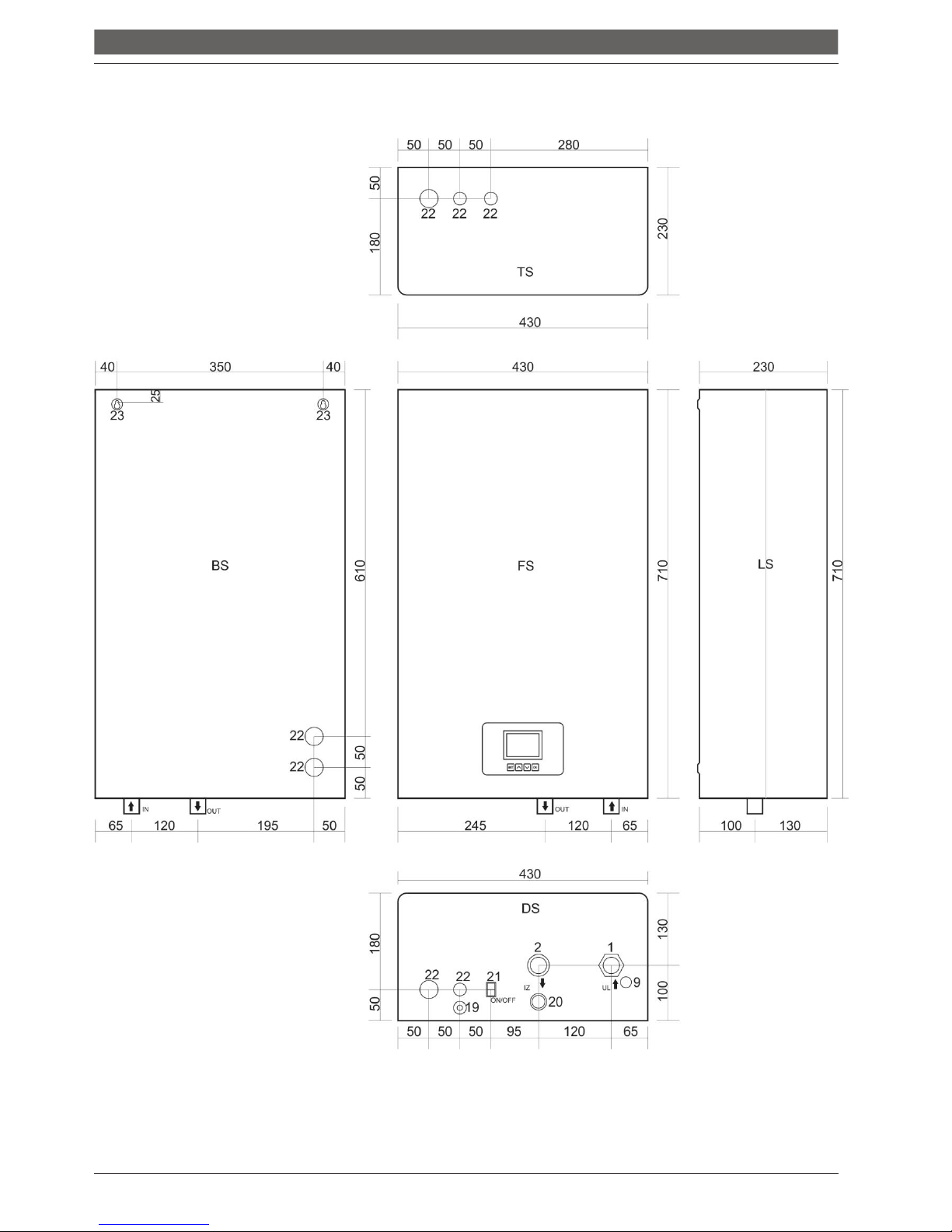
2.13 Dimensions and technical data
2.13.1 Dimensions and technical data for boiler Compact ePlus
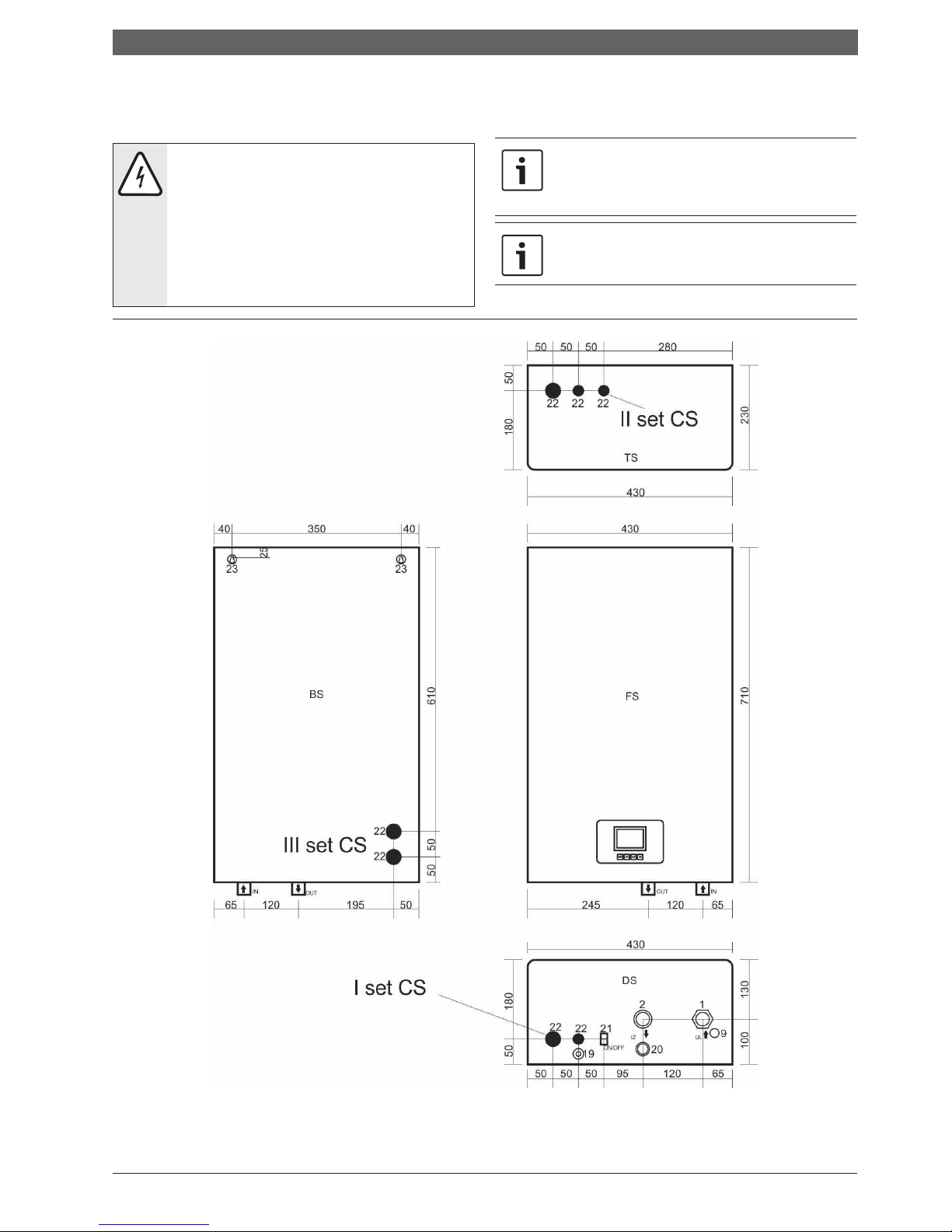
DS – Bottom side; FS – Front side; LS – Left side; TS – Upper side; BS – Back side
Image number 2 Dimensions and connectors
Page 11
Device data
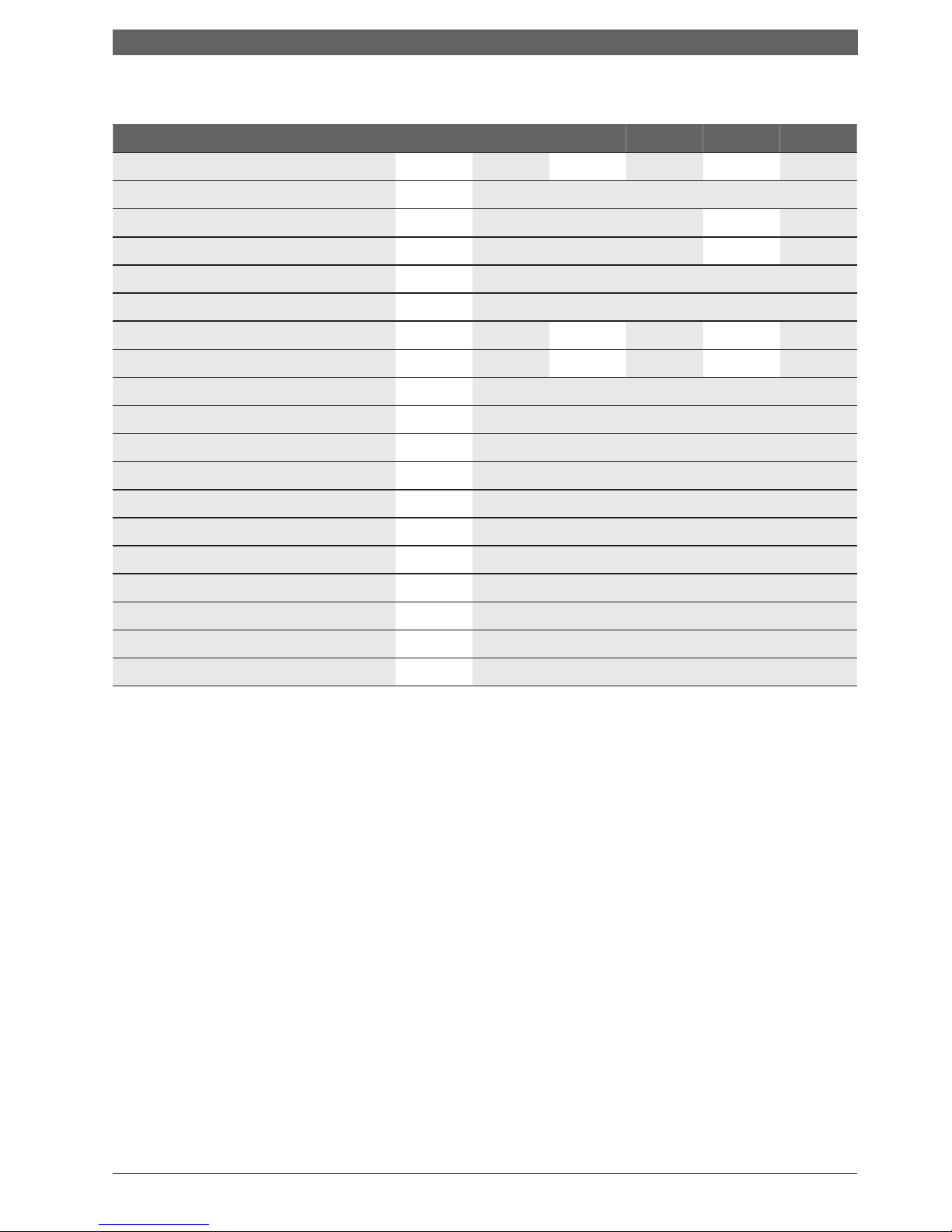
2.13.2 Technical data
Power
Degree of utilization
Number of degrees of power
Division of degrees of power
unit
ePlus
6
k
W
6
%
3
3x2
ePlus
9
ePlus
12
ePlus
18
ePlus
24
9 12 18 24
99
6 6 9 9
6x1,5 6x2 9x2 9x2,7
Network voltage
Protection level
Required fuses
V AC
3x400/230 50Hz
IP40
A
16 20 25 32 40
Minimum intersection of
introductory cable
Safety valve
Max. permissible operating pressure
Min. permissible operating pressure
Max. temperature
of the boiler
Volume of water in the boiler
Volume of expansion container
Connector of starting line
Connector of return line
Mass of device (without water)
mm 5x2,5
bar
bar
bar
˚C
l
l
col
co
l
k
g
5x2,5 5x4 5x4 5x6
3
2,2
0,8
80
12,5
7
G3/
4
”
G3/
4
”
25
Dimen
sions
mm
Processor umit
Table: Technical data of the device Compact ePlus
700x430x230 (HxWxL)
YES
Page 12
Transport
3.
Transpor
t
NOTE:
Transport damage
Pay attention to the transport instructions
that are written on the packaging.
Use a suitable transport vehicle, e.g. trolley for
bags with clamp tape.
The product should be in
the lying position during the transport.
Avoid impacts or crashes.
Put the packed boiler on the trolley for bags, if necessary,
secure it with the clamp strip and transport it to the place
where it will be set.
Remove packaging accessories.
Remove boiler’s packaging material and dispose of
it in an environmentally acceptable manner.
Page 13
Installation of the device
4.
Installation of the device
CAUTION:
Human or material damages
caused by improper installation!
Never install the boiler without an expansion
container (AG) and a safety valve
.
The boiler must not be installed in the protective
zone of the wet area and the area where a bathtub
is located.
NOTE:
Material damages from freezing!
The boiler may only be installed in rooms where
freezing cannot occur.
4.2 Distance
DANGER: Fire hazard due to flammable
materials or liquids!
Do not dispose of flammable materials or
liquids near the boiler.
Inform the user about applicable regulations
of minimum distances from highly flammable
materials ( chapter 2.8, page 7).
4.1 Be careful about the following
before installation
NOTE:
Material damages caused by non-
compliance with further instructions!
Follow the instructions for the boiler and all
installed components.
•
follow the regulations on electrical installations
and the minimum distances which are in force in
the countries concerned.
•
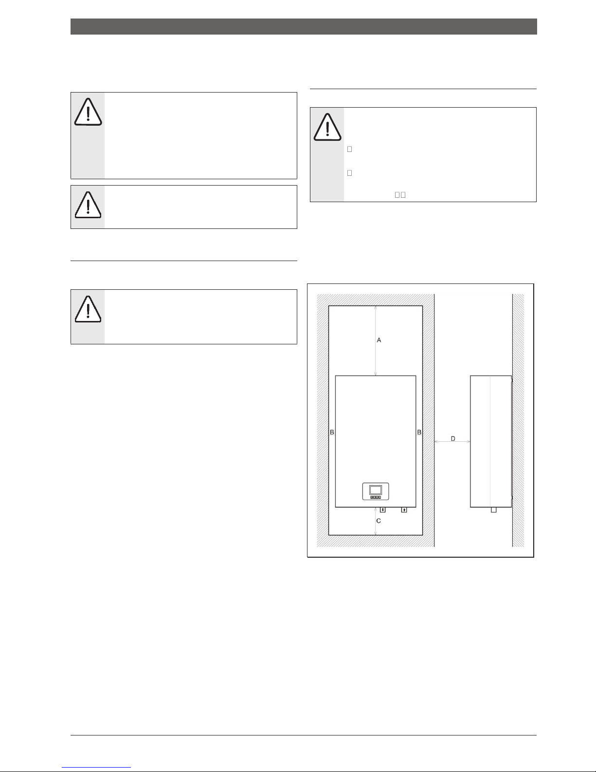
set the boiler on the wall in such a way that there remains the
minimum free space as shown in Image no.3
Before installing, keep an eye on the following
:
•
all electrical connections, protection measures and
fuses should be carried out by an authorized person,
complying with all applicable norms and regulations
as well as local regulations.
•
the electrical connection must be carried out according to
connection schemes.
•
after proper installation of the device, carry
out the grounding.
•
switch off the electric power before opening and
all operations.
•
unprofessional and unauthorized attempts of
connection can cause material damages to the device
and lead to dangerous electric shocks.
A = 500
mm / B = 50mm / C =
200
mm / D =
500
mm
Image number 3 Minimum distances during installation
Page 14
Installation of the device
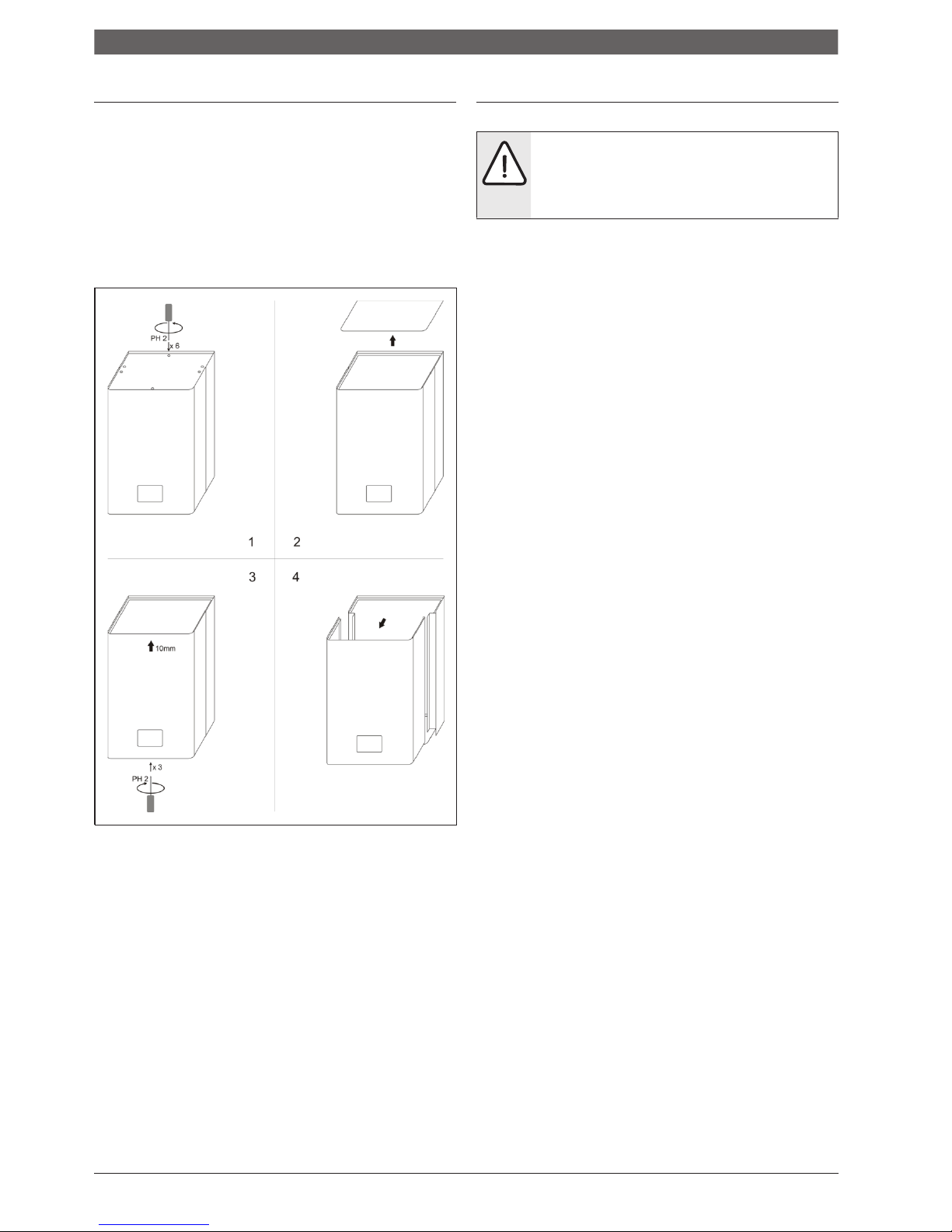
4.3 Disassemble the front cover of the boiler 4.4 Installation of the boiler
The shell of the boiler can be removed for easy handling and
installation.
Unscrew the screws on the top
cover.
Unscrew the screws on the bottom
cover.
With a slight pulling towards you, disassemble the front
shell of the boiler.
NOTE:
Material damages caused by
improper installation onto wall!
Suitable material for fixing should be used
This chapter describes installation of the boiler on the wall.
Draw the positions of openings for drilling for the installation kit
according to the dimensions shown in Image 2.
Take care when marking the openings for the installation
in order to allow the boiler to stand vertically.
Drill the holes in the wall with an adequate drill.
In the drilled holes, place the plastic anchors that are part
of the package of the device (or the anchors that are
adequate for some non-standard type of wall).
Then screw in the bolts that are supplied together with the
anchors (or some other) so that they stick out of the wall
min 5mm and maximum 10mm.
Carefully attach the device to the wall, make sure that the
boiler is installed vertically.
Fix the boiler from the inside with the nuts from the
installation kit.
Image number 4 Opening of the boiler (disassembling of the front shell)
Page 15
Installation of the device
4.5
Introduction of hydraulic connectors
NOTE:
Material damages caused by
throughput connectors!
Install the connection lines without connecting to
the connectors of the boiler.
NOTE:
Damages to the installation due to poor
water quality! Depending on the properties of the
water, the heating installation may be damaged
by corrosion or by the formation of limescale.
Follow the requirements for water for filling
according to VDI 2035, i.e. project documentation
and the catalog.
Connect the heating lines as follows:
Connect the return line to the IN connector.
Connect the starting line to the OU
T
connector
.
Check the pre-pressure of the expansion container.
Open the charging and discharging tap.
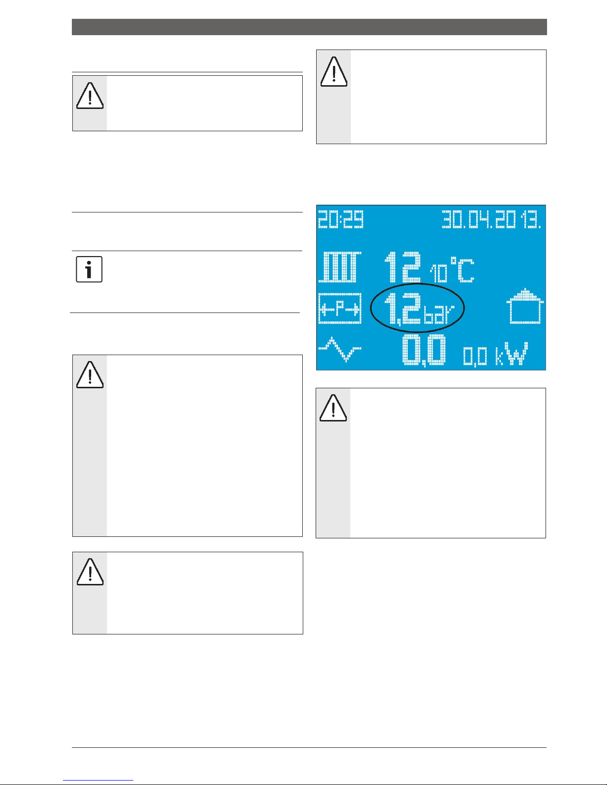
Fill the boiler slowly. Follow the pressure on the display.
4.6 Fill the installation and check the
impermeability.
Before filling the system, the boiler must be connected
to the electrical installation and switched on via the
ON/OFF switch on the bootom side of the boiler to the
STAND BY mode in order to monitor the value of
pressure in the installation.
4.6.1 Fill the boiler with water (demineralized water is
recommended) and test the welds and seals
The impermeability must be tested before putting the boiler into
operation.
DANGER: Injuries and/or material damages
can occur by exceeding the pressure during
the testing of impermeability!
High pressure can damage the control and safety
devices as well as the tank itself.
Fill the boiler with pressure that corresponds to
the pressure of the opening of the safety valve.
Observe the maximum pressure of the built-in
components.
After checking the impermeability, re-open the
valves.
Ensure that all control and safety parts
for pressure control work properly.
DANGER: Danger to health due to mixing
drinking water!
Be sure to follow national regulations
and norms to avoid mixing drinking water
(eg. with water from heating installations).
please follow EN
1717.
Image number 5 Display with highlighted pressure
NOTE:
Material damages caused by
temperature stress.
If you fill the boiler in a warm/hot condition, the
temperature stresses can cause cracks due to
straining. The boiler will start to leak water.
Fill the boiler only in cold condition (the
temperature of starting line may be maximally
40°C).
Fill the boiler only through the quick valve on the
boiler's pipe installation (return line).
Close the tap when the operating pressure is reached.
Discharge the air from the boiler through the valve for air
discharging
(image 5
and image 6).
Discharge the air from the installation via the valve on
the radiator.
When the operating pressure is lowered by discharging of
air, the water must be refilled.
Test the impermeability according to local regulations.
After checking the impermeability, open all the items
that you closed because of the filling.
Make sure all the security elements work correctly
If the boiler is tested for impermeability and no leakage has
been detected, set the correct operating pressure
Page 16
Installation of the device
Remove the hose from the tap for charging and
discharging.
Enter the values of operating pressure and water
quality in the operating manual.
At first or repeated charging or when replacing water
Follow the requirements for water for filling
4.6.2 Air discharging of the pump for heating and unblocking
The pump in this device has an automatic air discharger and
no action is required for air discharging from the pump.
When the heating pump is blocked, do the following:
Unscrew the large central screw on the front side of the pump.
Try carefully to release the shaft by using a screwdriver
which is inserted into the opening that covered the central screw.
Turn a few circles with the screwdriver until the rotor of the pump
starts to rotate slightly.
Return the central screwdriver to its place.
NOTE: With the release of the central screwdriver
there may occur leakage of a small amount of hot
water from the rotor of the pump’s impeller.
Perform these actions on a cold heating system.
4.6.3 Discharge air from the boiler
Carefully, by using the screw on the air discharger,
release the valve and discharge air from the boiler.
This
valve is also automatical so that if you comply with the
rule of slow filling of the installation and the boiler, no
additional manual discharging will be required.
Page 17
Electrical connector
5.
Electrical connector
DANGER: Life danger from electric shock!
Perform electrical works only with the
necessary qualifications.
Before opening the device, disconnect the
network voltage from all poles and ensure
that it is not activated again.
Follow the regulations for installation.
When connecting the boiler to the electrical
installation, take care of the connection scheme
and connection plans. Observe required cable
cross-sections and fuse power outside the boiler.
This device
is intended for connection to a
three-phase network
(3x
400/230
)
5.1 Position of the entry for the introduction of the power cable
I set CS / II set CS / III set CS – Position of the first set of Cable holders
Image number 6 Display of positions of entries of cables on the boiler
Page 18

This device is equipped with three (3) sets of entries for
introduction of power cables.
I set of entries for introduction of power cables (
main
set)
is located on the bottom side of the device.
They are
located on the bottom panel of the device in the rear left
corner. (see image 6)
They are intended for connection of
the device when the power cable comes from the bottom
side of the boiler.
II set of entries for introduction of power cables
is
located
on the upper side of the boiler and also in the
rear left corner (
see image 6). They are intended for
connection of the device when the power cable comes from
the upper side of the device.
.
III set of entries for introduction of power cables
is
placed from the inside of the device
on its
rear side,
and it is intended when cables in
the wall are prepared on time
and when the
place for the boiler is prepared. They allow the
power cable to directly enter from the wall into the
boiler.
When the front cover is removed, in the bottom left
side can be seen two openings of dimensions of 28 mm
and placed one above the other.
This way of connecting
provides only aesthetic function because the cables
are not visible. (see image 6).
Page 19
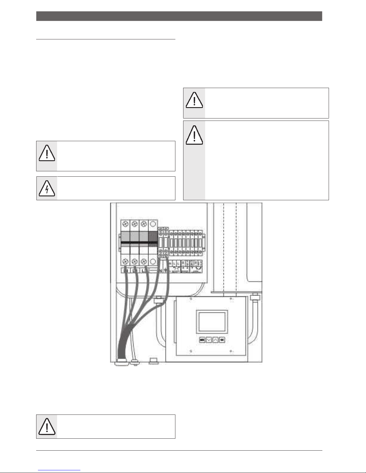
Ele
ctrical connector
5.2 Connecting the cable
- Connection is performed according to the installation
scheme in the image number 7.
- The neutral (zero) line is connected to the corresponding
regular clamp (N) located on the right side of the fuse set with
the voltage trigger.
The regular clamp of zero line is blue.
- Instead of the conventional regular clamp for connecting the
power cable, there are three-pole automatic fuses in the
boiler, into which the power cable is introduced.
The three-pole
set of automatic fuses has been upgraded with a remote voltage trigger
so that a safety circuit is achieved which, in addition to short-term
electricity protection, responds to thermal overload (the signal from the
safety thermostat activates the voltage trigger) and at the same time
interrupts the supply of all three phases into the device.
- The phase conductors are connected to a three-pole fuse (L1, L2,
L3)
ATTENTION! When connecting the phase
conductors, be sure to tighten the screws in the
automatic fuses in order to achieve the best
possible connection between the cable and the
clamp. Pr
ili
kom povezivanja faznih
- Connect the line for grounding to the regular clamp which is marked
with the sign for grounding. The regular clamp of the line for
grounding of the device is green and yellow.
NOTE: The remote voltage trigger is factory-
connected within the safety set of the device
and NO cable is connected to it subsequently.
NOTE:
The room thermostat is connected to the
additional regular clamps (5V, IN) and it interrupts
the voltage of 5V DC which comes from the
processor panel of the boiler.
- It is necessary to use room thermostats with
independent power supply eg. Battery, or Centrometal
room thermostat EST113 R5
DANGER!
If a good connection between the cable
and the clamp is not achieved there may
come to uncontrolled heating of fuses and
their failure.
-
This boiler is not intended to operate without
a room thermostat or an external control unit
Image number 7 Scheme of connection of power cable
- When introducing a power cable into the boiler, through
any selected set of entries for introduction, carefully pull
through the cable to the three-pole automatic fuses to
avoid damaging the cable sets inside the device.
NOTE! The connection of this device must
be carried out by a person that is qualified
to perform this kind of work.
- When you are finished with the connection of the
power cable and room thermostat, it is necessary to lift
the fuse set together with the remote voltage trigger
before closing the device, that is, before installing the
front cover, in order to ensure the power supply to the
boiler.
Page 20
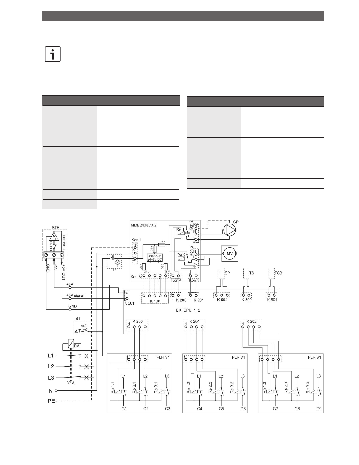
Electrical connector
5.3 Connection scheme
All of the above-mentioned cable cross-sections
are minimum cross-sections.
The sections to be
set depend on the length of the line and the
method of setting.
Dimension the cable cross-sections according to
local regulations.
Legen
d
YES
Remote voltage trigger
3P A
Three-pole automatic fuse
ST
Safety thermostat Klikson
ST
R
Room thermostat
+5V,
+5V ulaz,
GND
Connection clamps of the room
thermostat
ATTENTION: 5V D
C
(only for EST 113 R5)
P
1
Main switch ON/O
FF
Re1/Re2
Rel
ay pump
s / Relay motor valve
CP / MV
Pump / Motor valve
S
P
Pressure sensor
Legen
d
TS/TSB
Temperature sensor of the boiler
OS
1
Electric fuse
230V T500m
A
OS
2
Electric fuse
230V T2
A
OS
3
Electric fuse 8V T
500m
A
OS
4
Electric fuse 24V T
500m
A
Re1.1, Re2.1, Re1.3
Rel
ay heater
on the panel PLR V
1.1
Re2.1, Re2.2, Re2.3
Rel
ay heater on the panel PLR V1.2
Re3.1, Re3.2, Re3.3
Rel
ay heater on the panel PLR V1.3
Table 2: Legend of connection schemes
Compact ePlus
Image number 8 Management scheme for Compact ePlus
Page 21

Page 22
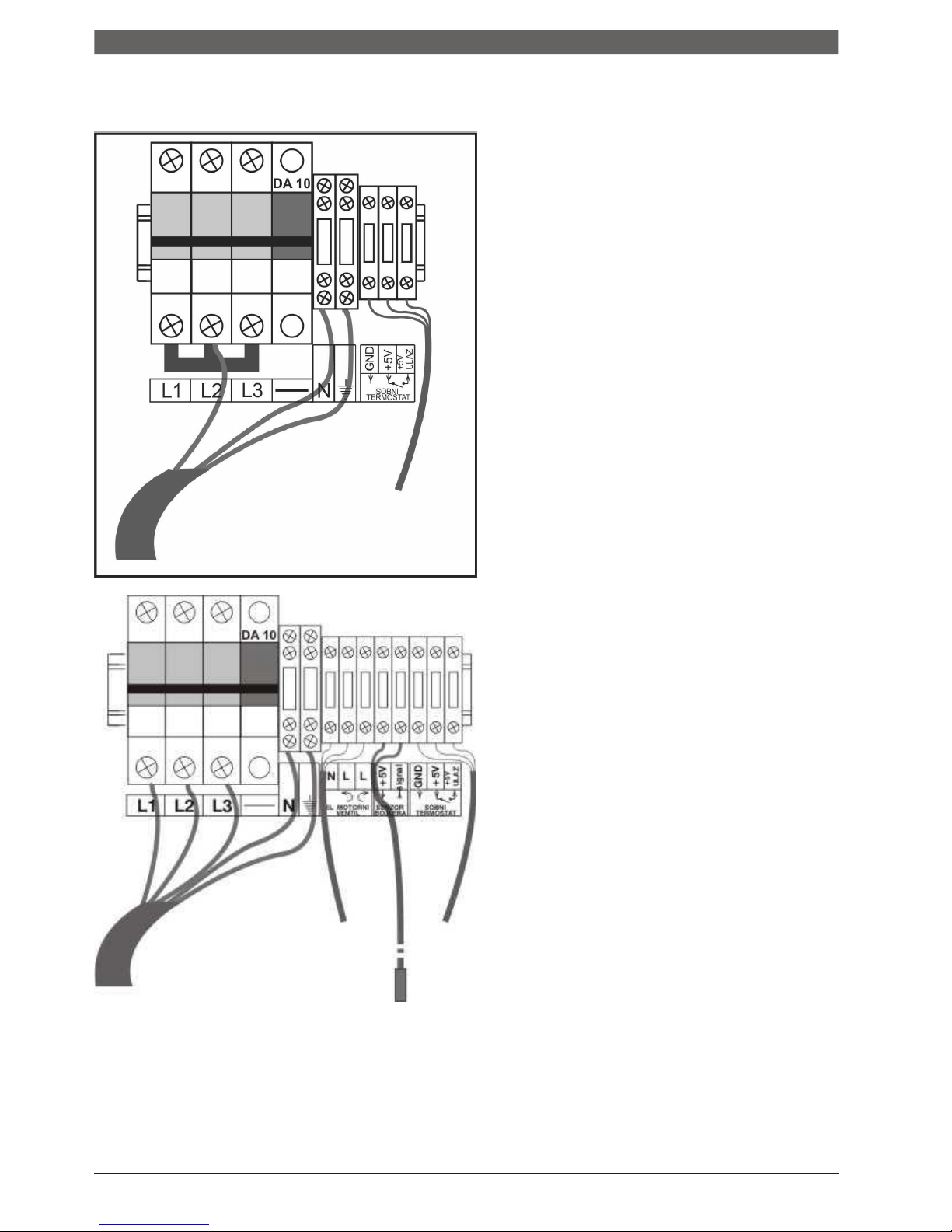
Electrical connector
5.4 Power cable connection scheme
Image of power cable connection sheme.
- Scheme of connection of the
clampsand connection of the boiler to a
single phase power supply
- Only for models:
- Compact ePlus 6kW
- Compact ePlus 9kW
Scheme of the connecting clamp and connection of the device to three-phase power supply
Page 23
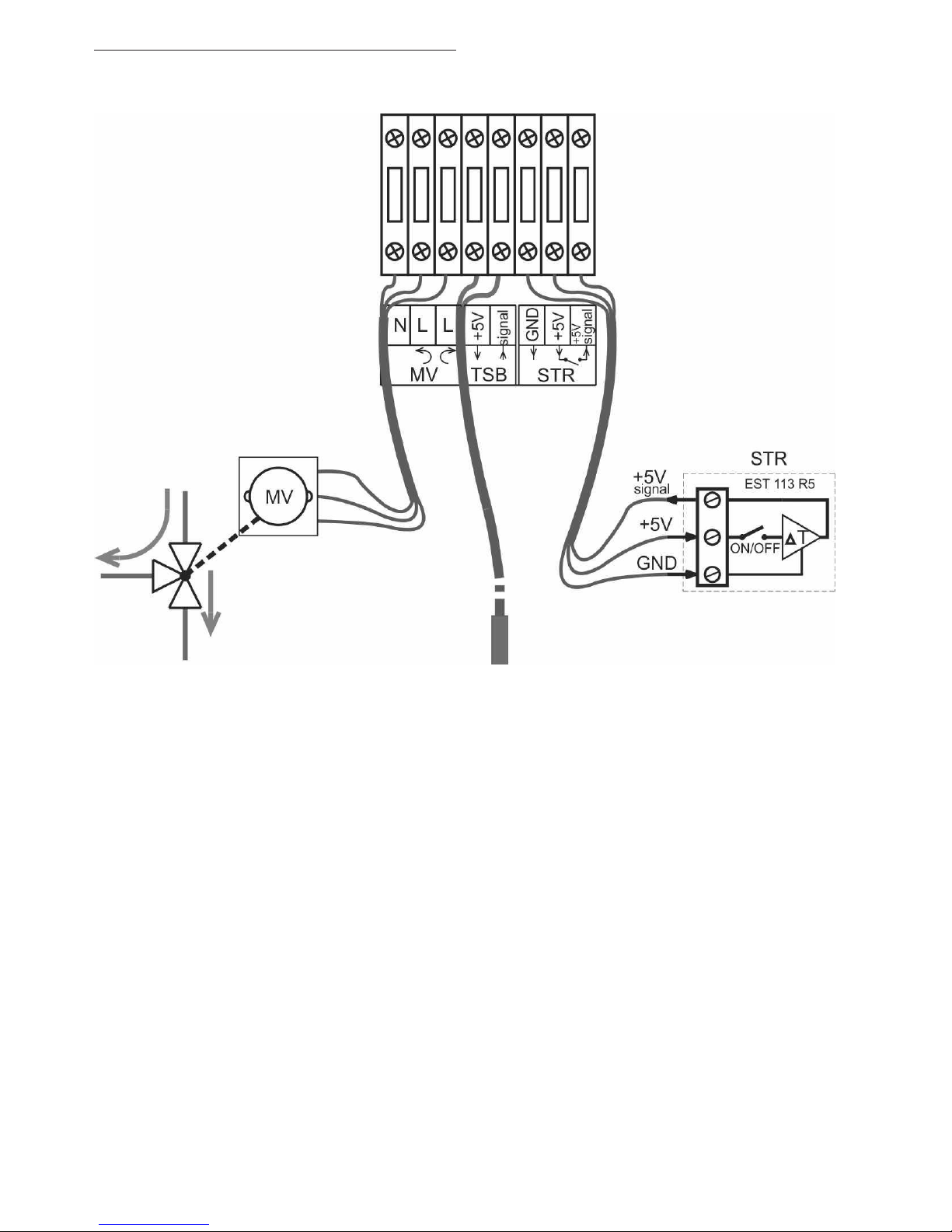
5.5 Connect the external control of
the boiler (room thermostat)
Scheme of connection of room thermostat, probe for measuring the temperature in the boiler and control
of the motor three-way valve.
Note: As shown in the scheme, the room thermostat CENTROMETAL EST 113 R5 is connected, and if
another thermostat is used, the clamp with the GND marking is not connected.
WARNING: Use a room thermostat with zero-voltage contacts.
The management of the preparation of sanitary water is an option.
Page 24
Putting into operation
6.
Putting into operation
After completing the works described below, complete the
report on the putting into operation (chapter 6.3).
6.2 First putting into operation
NOTE: Material
damages caused by
6.1 Before putting into operation
NOTE:
Material damages caused by
unprofessional handling!
Putting into operation without sufficient amount
of water destroys the device.
Always switch on the boiler and use it only if it has
enough water.
The boiler
must work with a minimum pressure of
0.8 bar.
improper handling!
Inform the client/user of the device about
handling with it.
Before first putting into operation, check that the heating
installation is filled with water and air-discharged.
Turn on the main switch (on the bottom side of the device)
All parameters of the heating system and the device itself
will appear on the display
The device is factory set to operate in the heating mode
(preparation of sanitary water is swithched off).
Set values:
temperatu
re of
10°C
and power
of 0 kW
.
Prior to putting into operation, check that the following
elements and connections are properly connected and function
correctly
:
•
Impermeability of the heating installation
,
Only the value of pressure in the installation will be the
one you set on the display when filling the installation with
water.
•
all pipes and armature,
•
all electrical connectors.
6.3 Record on putting into operation
Putting into operation
Page
Measures/values
Notes
1. Boiler type
2. Serial no.
3.
Set thermostatic regulation
4.
Fill and discharge the air from the heating installation and
check the impermeability of all connectors.
16
5.
Establishing operating pressure
•
Check the pressure of the expansion container
__________ bar
__________ bar
6.
Tested security devices
16
7.
Set the electrical connector according to local
regulations
16
8.
Check of the functions of the device
16
9.
Users informed, technical documentation submitted
10.
Confirmation of professional putting into operation
Seal of service technician / signature / date
Table: Record on putting into operation
Page 25

Handling the heating installation
7.
Handling the heating
installation
7.1 Instructions for operation
Safety instructions
Ensure that the boiler is operated only by adults
familiar with the instructions and operation of the
boiler
.
Make sure that children are not kept unattended in the
area of the boiler
.
Do not leave or store easily flammable objects within a
safety distance of 400 mm around the boiler
.
Flammable objects must not be placed on the boiler.
The user must comply with the operating instructions.
The user may only switch on the boiler (except for the first
putiing into operation), set the temperature on the control unit and
put the boiler out of the drive.
All other works must be carried
out by an authorized service technician.
The authorized person who carried out the installation
is obliged to inform the user about the handling and the
correct, safe operation of the boiler.
The boiler must not work in case of danger of explosion,
fire, emission of gases or steam.
Beware of the flammability properties of the components
(
instructions for installation and maintenance).
Page 26
Handling the heating installation
7.2 Overview of handling elements
The boiler can work in four (4) regimes
.
1
Heating
,
2 Preparation of sanitary water,
3 Heating and sanitary water,
7.2.1 Functions of the device
4 Freezing protection regime
We will briefly introduce you to the most important
characteristics of the boiler
Compact ePlus
- Electric boiler Compact ePlus contains all elements of
boiler substations ie. small boiler rooms.
-
Unlike previously known models, this model has many
advanced functions that not only make it easier to work
with the device, but also provide a longer life and safer
operation of the device.
- The temperature sensors and sensors of the hydraulic
pressure of the water in the installation monitor changes in
the system and send information to the processor that
processes them and controls the boiler based on them.
- Communication of users and service technicians (installers) with
the device is facilitated and improved through a display showing all
the essential parameters of the device and the system itself.
7.2.3 Heating regime
- Depending on the power of the boiler, the power can be
adjusted in steps
Pwer of the boiler
steps (kW
)
6 k
W
2+2+2
9k
W 1,5+1,5+1,5+1,5+1,5+1,5
12k
W
2+2+2+2+2+2
18k
W
2+2+2+2+2+2+2+2+2
24k
W
2,7+2,7+2,7+2,7+2,7+2,7+2,7+2,7+2,7
Table 3 Power and steps of adjusting the power
- The setup is facilitated and performed by four buttons
located just below the display.
- The processor takes care of
:
- Even load of phases no matter of the power
on which is set the boiler.
- Even load of output relays and heaters.
- If necessary, the relays and heaters that have been
switched on for a long time are switched off, and relays
and heaters that were inactive switche on instead.
- In this way, the electrical network is symmetrically loaded,
and all elements of the boiler work equally, thus achieving a
longer lifetime of exploitation of the device
.
Operating temperature
-
is set in steps of/from 1 °C
-
The operating temperature range ranges from 10 °C to 80 °C
Switching on and off
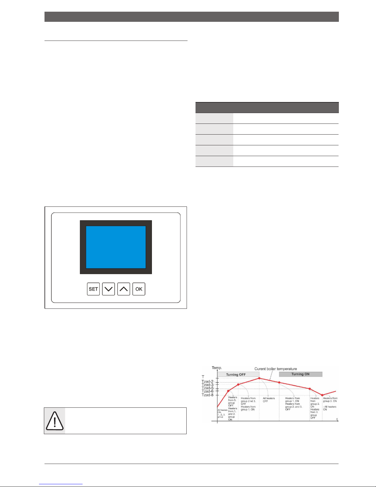
the heaters
-
Image number 9 Display and push-buttons
is carried out periodically with a 3-second intervals with
division of power in three (3) groups which are
temperaturely-shifted by 3 °C.
The overview of switching on and off is given in image 10
7.2.2 Basic settings
- It is necessary to set the operating pressure to 1.2 bar (+
0.4) for normal operation of the device when filling and
discharging air from the heating system.
- If the operating pressure is less than 0.8 bar, a warning will
appear on the display (see table 3 Warning signs) and if
the operating pressure continues to fall and drop below 0.4
bar, the boiler will be switched off with the error information
on the display.
- If the operating pressure is greater than 2.2 bar, a
warning will appear on the display, and if it exceeds 2.6
bar, the boiler will be switched off with the error
information on the display.
ATTENTION!: I
f the operating pressure continues
to increase, the mechanical safety valve will open at
3 bar and release the part of the water from the
boiler, until the pressure drops to the allowed value.
-
The circulation pump has the choice of three (3)
powers of 40W, 59W and 84W.
Image number 10 Switching on and off the heaters
Page 27
Handling the heating installation
Circulation pump WILO MSL 12/5 OEM
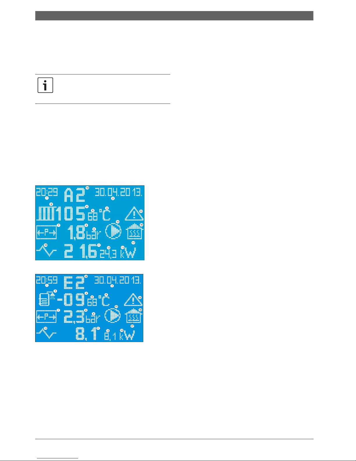
7 The symbol of the container under pressure
-
is switched on on the command of the room thermostat.
-
the room thermostat also switches off the heaters and
the pump when it reads the temperature which is set
in the room.
If the room thermostat does not switch on the
pump for some reason, the heaters will not
switch on as well.
The error message will
appear on the display.
- If the boiler has reached the set water temperature in the
system, the heaters will be switched off and the pump will
continue to work for an additional 2 minutes.
8 Pressure in the system (possible display from 0 to 3.6 bar with one
decimal)
9
Symbol of measuring unit of pressure(bar)
10
Symbol of electricity
11 Current power of the boiler in kW (
display with one decimal
)
12 The set power of the boiler in kW (displayed with one
decimal)
13 Symbol of measuring unit of electricity (kW)
15 Symbol of the circulation pump (appears only when the pump is
switched on
)
Freezing protection regime
:
-
Pump is always switched on
16
Symbol of space that is heated (house)
17 Symbol of switched on room thermostat
-
The power of the boiler is 1/3 of the nominal power and
cannot be changed.
-
Operating temperature is fixed to 10°C
and cannot
be
changed
.
- Sobni termostat nema uticaj na rad kotla.
18 Warning symbols (A0-A4)
or error symbols (E0-E6)
19 Symbol of danger (appears when the value of pressure or
temperature exceeds
the permitted limits
)
7.2.5 Warning symbols (
codes
)
7.2.4 Symbols that may appear on display
A
1
- warning: Approaching the lower limit of the allowed
operating pressure (0.8 bar)
A2- warning:
Approaching the upper limit of the allowed
pressure (
2.2 bar
)
A3- warning:
Approaching the lower
limit of the allowed
temperature (5°C
)
A4- warning:
Approaching the upper
limit of the allowed
temperature (
80°C
)
7.2.6
Error symbols (
codes
)
E0-
error:
The set parameters are not with8in the limits
(this situation is practically impossible if the
eeprom is not empty and the boiler is switched on for the first time)
E1-
error:
Pressure value below the lower limit (0.4 bar) ALL SWITCHED OFF
E2-
error:
Pressure value above the upper limit
(2.6 bar) ALL
SWITCHED OFF
E3-
error:
Temperature value of the boiler equal or bellow the lower
limit (
3°C)
ALL SWITCHED OFF
E4-
error:
Temprature value of the boiler equal or above the
upper
limit (85°C)
ALL SWITCHED OFF
E5-
error:
Temperature value of the boiler equal or bellow the lower limit (3°C)
I
NFORMATIVE
E6-
error:
Temperature sensor of the boiler in break or in short
circuit ALL SWITCHED OFF
E7-
error:
Temperature sensor of the boiler in break or in short
circuit ALL SWITCHED OFF
E8-
error:
Sensor of the pressure in break or in short circuit
ALL SWITCHED OFF
Image number
11 and 12 Symbols on the display
1 Time
2 Dat
e
3 Symbol of radiator (temperature of the system) or symbol of the boiler
4 Current temperature of the system (possible display from -99 to 99 °C)
5 The set temperature of the system (possible display from 10 to 80 °C)
6 Symbol of measuring unit of temperature
(°C
)
Page 28
Handling the heating installation
7.3 Heating regulation
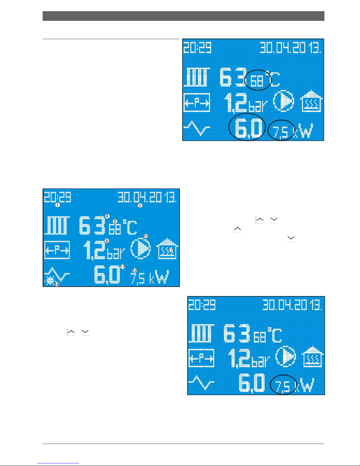
Setting heating parameters
Based on the display on the screen (Image 13), there can be
read
:
1 Time
2
Dat
e
4 Current temperature of the system
5 The set temperature of the system
8 Operating pressure in the system
11
Current power
12 The set power of the boiler
15 Information on operation of the pump
- if the pump symbol is on the screen the PUMP is
SWITCHED ON AND WORKS
17 Information on the status
of
the room thermostat
- if the symbol is on the screen
the
ROOM
THERMOS
TAT IS SWITCHED ON
current set
values
Image 14 Setting the operating temperature of the boiler
Setting the power of the boiler
-
If a change is confirmed after the temperature is set (press OK),
the controller switches to power adjustment. If we do not want to
change the temperature, but only the power, when the value of
the set temperature begins to flash, press the OK button and
switch to the power setting of the boiler.
The set value of power
of the boiler starts to flash, and it is now possible to increase or
decrease it by using the buttons
Each use of the button
increases the power of the
Boiler by 1,5kW, and every use of the button
reduces the
power of the boiler by
1,5kW.
So,
it is possible to set one of
the following values of power of the boiler: 1,5kW; 3kW ;
4,5kW
;6kW ;
7,5kW ; 9kW (FOR BOILER OF 9kW POWER).
The change must be confirmed by pressing the SET button.
If the change is not confirmed, after 15 seconds from pressing any
button (except SET), the controller continues to operate according
to the old value of the set power and exits the setting mode.
Image 13
Setting operating temperature of the boiler
- By pressing the SET button you enter the mode for setting
parameters. The set operating temperature of the boiler is
flashing, which can now be increased or decreased with the
buttons and Each press on the button increases or
decreases the operating temperature of the boiler by one °C.
The change must be confirmed by pressing the SET button.
If
the change is not confirmed, after 15 seconds from pressing any
button (except SET), the controller continues to operate according
to the old value of the set temperature and exits the setting mode.
C
Current power Set power
Image 15 Setting the power of the boiler
Page 29
Handling the heating installation
Setting time and date
In the setting mode of the boiler’s operating mode,that is, by
selecting a function by pressing the OK button you can go
through all the elements that can be set.
When we get to the
time and date, first the hours will start to flash, then the minutes
and then the year, the month and the day. Setting is done by
using the buttons ▼▲.
Change of parameters is confirmed by pressing the SET button.
- Freezing protection regime
is described in item
7.2.3
(
see image 18
)
Image 18 Position of symbols for selection of operating
r
egime of the boiler
Image 16 Setting time and date
By pressing the OK button, this mode is activated in which
the fixed temperature is maintained at 10 °C and the fixed
power of the boiler (1/3 of the minimum power)
The pump is always switched on in this regime and the room
thermostat has no effect on the operation of the boiler.
If the change of operation regime is not confirmed by pressing
OK button, after 15 seconds from pressing any button (except
OK), the controller continues to operate in normal heating
regime.
If the change is confirmed after setting time and date, the
controller switches to setting the operating regime, that is,
selection of normal operating regime or the regime of freezing
protection system.
Warnings on the display (pressure and temperature)
Warnings related to operating pressure
Selection of the operating regime of the boiler
It is carried out by setting the functions of the boiler
- When the operating pressure in the system is less than 0.8
bar or greater than 2.2 bar, the current value of pressure
starts to flash.
- A warning triange, which flashes all the time,
appears
in the upper right side of the display below
the date (image 19)
Image 17 Position of symbols for selection of operating regime
of the boiler (
heating regime)
Image 19 Warnings related to operating pressure
1) This operating regime of the boiler is confirmed by pressing
the
SET
button. Operating regime of heating is
described in item 7.2.3.
- A1
for operating pressure below 0.8 bar
- A2
for operating pressure above 2.2 bar
- And exits the setting mode.
The boiler still works normally. If the pressure drops below
2) If the following button
is pressed, instead
of the snowflake,
0.5 bar or increases above 2.5 bar
there appear the symbol checked or the bin which
flash on the display and show the operating regime
.
Selected regime is confirmed by pressing the SET button.
Page 30
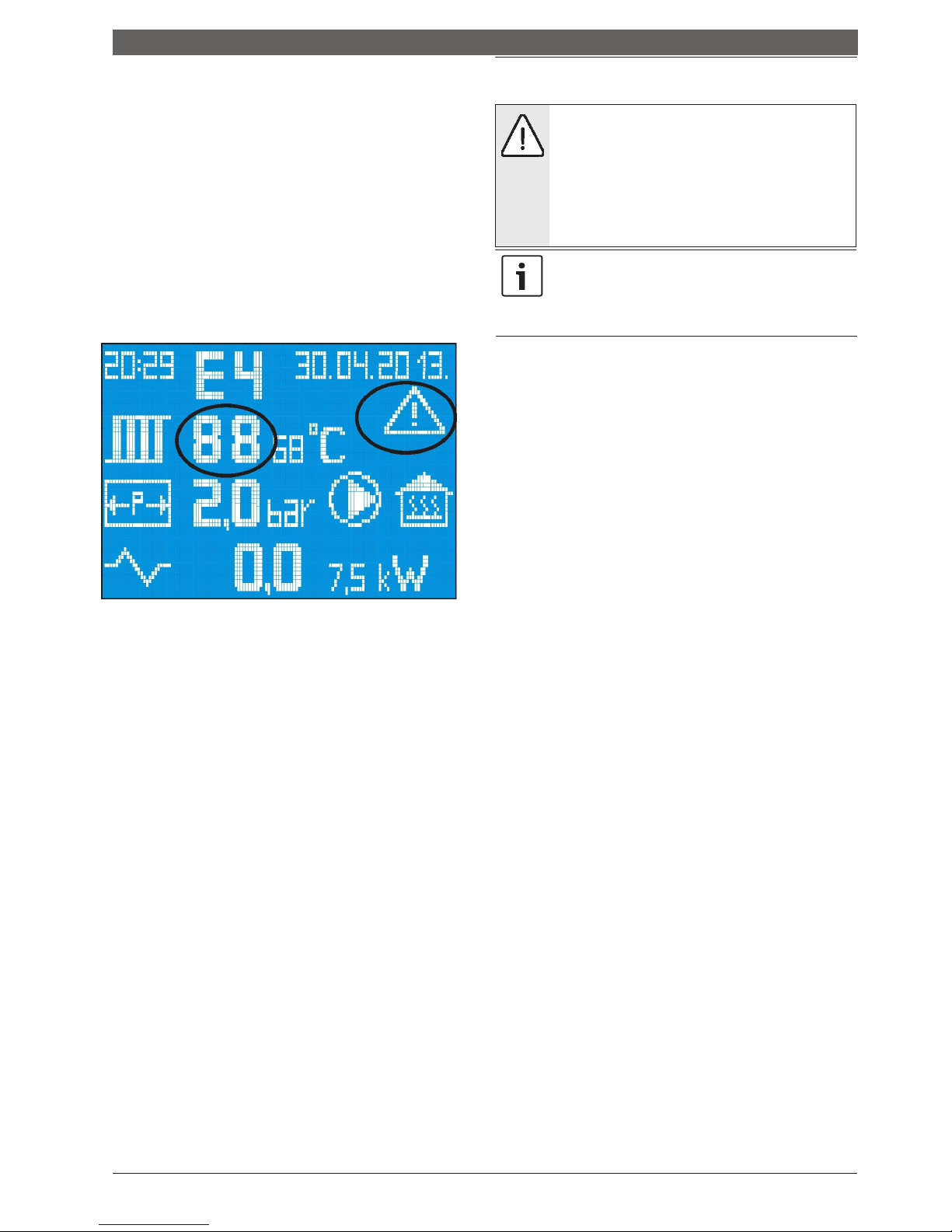
Handling the heating ins
tallation
the heaters switch off, and the warning code shifts
to
error code.
7.4 Putting the boiler out of operation
- E1
for operating pressure below 0.5 bar
- E2
for operating pressure above 2.5 bar
.
WARNING:
Material damages caused by
freezing
!
In order to keep the boiler working, it is necessary to
bring pressure within the normal value limits. Image 19.
Warnings related to temperature
If the heating installation is out of operation, it could
freeze at low temperatures.
Protect the heating installation from freezing.
Empty the installation if there is a risk of freezing
-
When the temperature in the system is less than 5°C or
higher than 80°C, the current value of temperature
starts to flash, and a warning triangle is displayed that
continuously flashes as well as warning codes (Image
20).
and if the boiler is out of operation.
When the device is put out of operation for a long
time, the pump of heating can be blocked.
To
remove the blockage, it is necessary to act as in the
case of discharging of air
(
chapter 4.6.2).
Place the main switch on the control panel in position “0”
(switched off).
Protect the heating installation from freezing.
Empty all lines completely.
Image 20 Warnings related to temperature
- A3
for temperature below 5°C
- A4
for temperature above 80°C
If the temperature drops below 3°C, the heaters and the
pump switch off, and the warning code shifts into the
error code:
- E3
for temperature below 3°C
The heaters will switch off if the temperature rises above 85°C
,
and the pump
works regardless of the room thermostat, and the
warning code shifts to
error code
:
- E4
for temperature above 85°C.
To keep the boiler working, the condition is that the temperature
returns to normal values.
7.3.1 Regulator of room temperature
If the regulator of room temperature is used, it must be
installed in the reference room.
Control of the temperature
of all rooms by the heating system is
carried out by this remote control.
Radiators in the reference room should not be equipped with
thermostatic valves, or they must always be open.
All radiators in
other rooms can be equipped with thermostatic valves.
7.3.2 Cease of heating
The
temperature of the boiler must be lowered
in the short-term
cease of heating by using
boiler’s
thermostatic regulator
.
To prevent
the freezing of the heating installation,
the temperature
Of the boiler must not be set below 5˚C. The boiler
must be put out of
operation in case of longer cease of heating
(
chapter 7.4).
Page 31
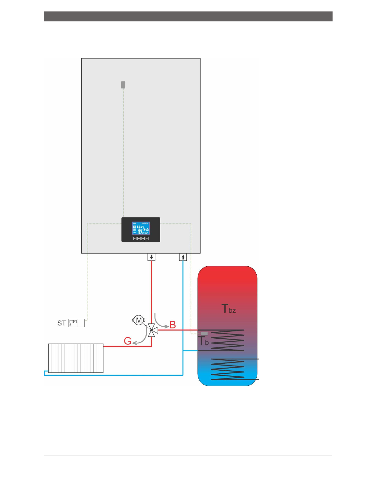
Operating principle of
CompactePlus
Overview of the use of the electric boiler
Compact ePlus in systems of heating and
preparation of sanitary water
NOTE: Perform setting and selecting of the regime in which the boiler will operate only
when the room thermostat does not require heating and when the basic elements of the
boiler, such as pump and heaters, are not included.
Page 32
Setting the operating regime
7.5 Sanitary water preparation regime
The Compact ePlus device has the option of controlling a
three-way motor valve in order to enable the heating of
sanitary water in the boiler with a heat exchanger.
7.5.1 Setting desired regimes
In order to select the desired operating regime of the
device, press and hold the SET button for more than 3
seconds. Then an overview will appear on the display
as in Image 21.
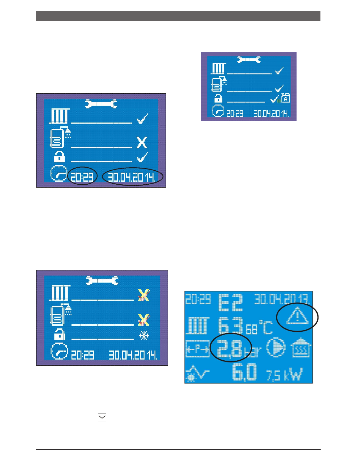
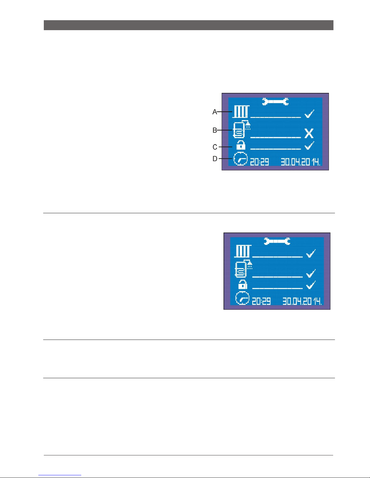
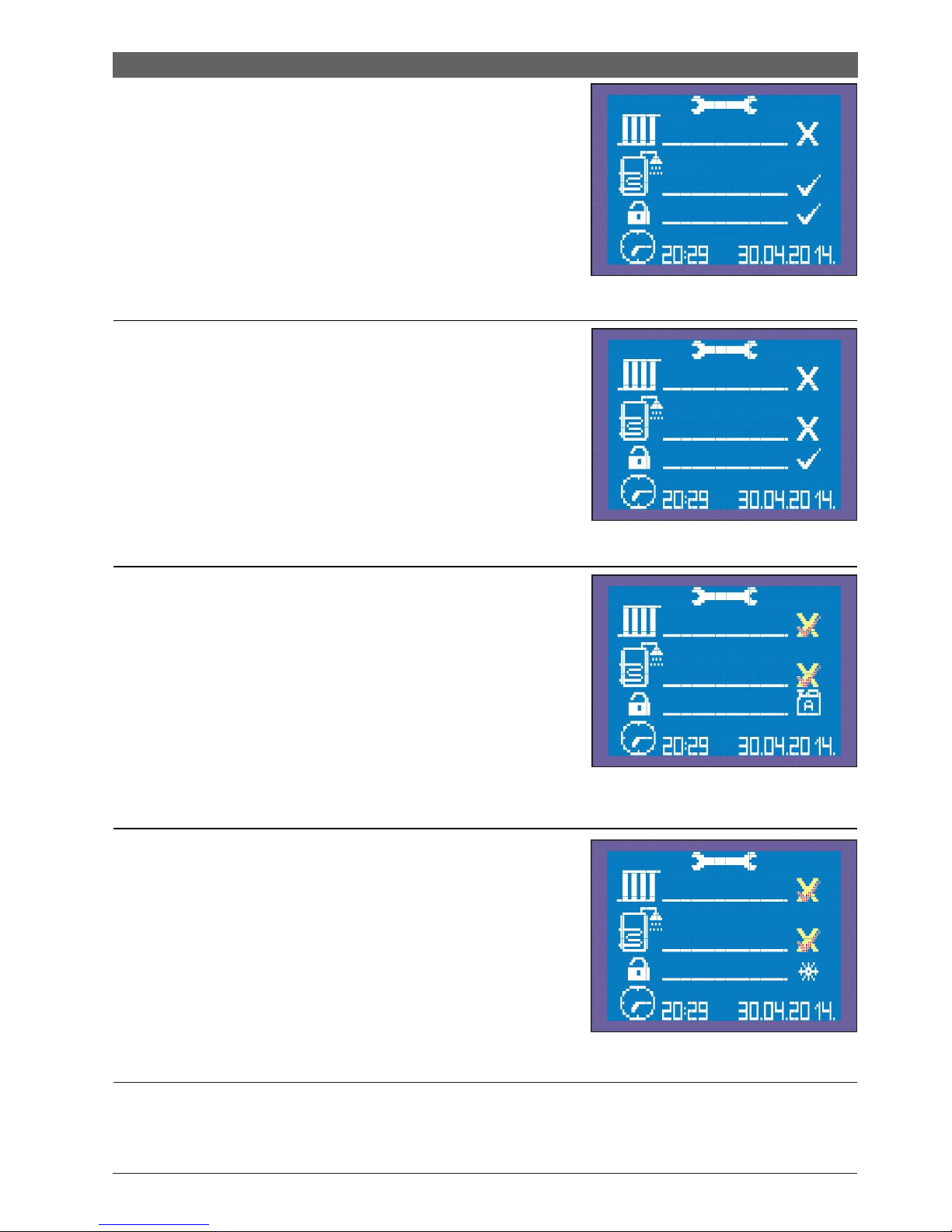
A) Symbol of heating regime
B) Symbol of sanitary water preparation regime
C) Selection of security mode at low temperatures
D) Symbol of clock for setting time and date
Desired regime is chosen by simply selecting the
symbol and its setting (X) SWITCHED OFF (√)
SWITCHED ON
Symbols are changed by pressing the ▲▼buttons.
1. Setting HEATING (ON) – SANITARY WATER (OFF) - Safety STANDARD Image 21 (Above)
2. ALL SWITCHED ON. Regimes of heating and preparation of sanitary water are switched on
Safety: standard setting.
The boiler will operate normally when the room thermostat requires
room heating.
When the room thermostat switches off the boiler, that is, when the
room is warmed, processor reads temperature in the boiler and if it is
lower than the set one it gives the command to the boiler to heat the
sanitary water by the three-way motor valve which is run by the
boiler.
STANDARD Safety – which means that the device is not set to antifreezing mode and that there is ordinary water in the system and not
the thermofluid.
Setting HEATING (ON) – SANITARY WATER (ON) Safety STANDARD
Image 22 (above)
NOTE: Perform setting and selecting of the regime in which the boiler will operate only when the room
thermostat does not require heating and when the basic elements of the boiler, such as pump and heaters,
are not included.
Page 33
Setting the operating regime
3. Heating SWITCHED OFF , preparation of sanitary water
SWITCHED ON. Safety STANDARD.
The device is only allowed to operate the regime of heating the sanitary
water in this regime. The device will control the temperature in the
boiler and will switch on the heaters and the pump if necessary.
The room thermostat has no effect on the operation of the boiler in this
setting.
Setting HEATING (OFF) – SANITARY WATER (ON) - Safety STANDARD image 23 (above)
4. Heating and preparation of sanitary water SWITCHED OFF
Safety STANDARD
The boiler will not work either on heating or on the preparation of
sanitary water in this regime.
Both the room thermostat and the probe for measuring temperature in
the boiler have no effect on the boiler.
Safety at a standard level means that if temperature in the system
drops below 3˚C the boiler will not switch on for safty reasons until the
temperature in the system exceeds 3˚C.
There is a risk of freezing of the installation in this setting.
Setting HEATING (OFF) – SANITARY WATER (OFF) - Safety STANDARD image 24 (above)
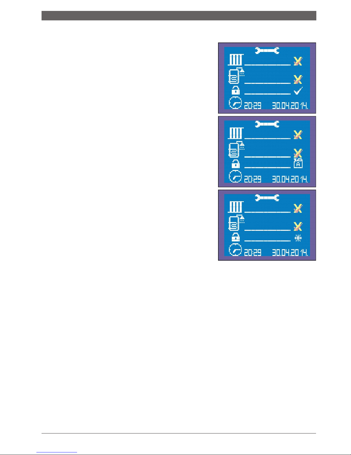
5. Heating and Sanitary water SWITCHED ON OR SWITCHED OFF
Safety BIN
The boiler works normally and controls the set regimes, regardless of
which of the two regimes are in function or both. The heating regime
always has advantage
Safety BIN means that the system is filled with the mixture of water and
thermofluids.
In this setting, if the temperature in the system drops below 3˚C, the
device will work normally when it is required of it.
image 25
Setting HEATING (ON/OFF) – SANITARY WATER (ON/OFF) - Safety THERMOFLUID in the system
6. Heating and sanitary water SWITCHED OFF OR SWITCHED ON
Safety SNOWFLAKE
Anti-freezing regime. The boiler works according to factory-set
parameters (see the description of anti-freezing regime).
The device protects itself and the heating system against low
temperatures.
This mode is also called WINTER HOLIDAY MODE.
image 26
Setting HEATING (ON/OFF) – SANITARY WATER (ON/OFF) - Safety ANTI-FREEZING
NOTE: Perform setting and selecting of the regime in which the boiler will operate only when the
room thermostat does not require heating and when the basic elements of the boiler, such as
pump and heaters, are not included.
Page 34
Setting the operating regime
Description of the SAFETY regime
Checked everything works according to the rules given for the specific
mode defined by the combination of the selected symbols in
the first two items of the menu. The program protects the
heating system from low temperatures by not allowing the
operation of the boiler on temperature of 3˚C or below (which
is measured by the sensor in the boiler) because there is a
risk that the installation is frozen.
Bin a system filled with a mixture of antifreeze and thus protected
from freezing. Everything works according to the rules given
for the specific operating regime which is defined by the
combination of selected symbols in the first two items of the
menu, but a part of the program that blocks the operation of
the boiler at a temperature of 3 °C or lower is switched off. In
other words, operation of the boiler is allowed regardless of
the possible low temperatures in the boiler. Also, there is no
need to warn about approaching to the lower limit of the
allowed temperature, as well as about the low temperature
errors.
Snowflake activated freezing protection regime. This regime is designed
to protect against freezing of the system in a shorter period
(10 days), e.g. during winter, when there is no need for
heating in the house (apartment), but due to low outdoor
temperatures. There is a possibility that the system freezes if
the heating is switched off and the system is not filled with
antifreeze. The pump operates non-stop in this regime,
maintaining the temperature of the system from 7-10˚C by
using 1/3 of the nominal power. The relay of the boiler is
switched off for 20 minutes and switched on again for 10
minutes to protect the heat exchanger in the boiler. When this
regime is selected, the first two items of the menu are
automatically de-checked, and no setting can be made until the
safety mode changes and one of the other two signs (operating
regimes) is selected instead of the snowflake.
Page 35
Setting the operating regime
Operating regime
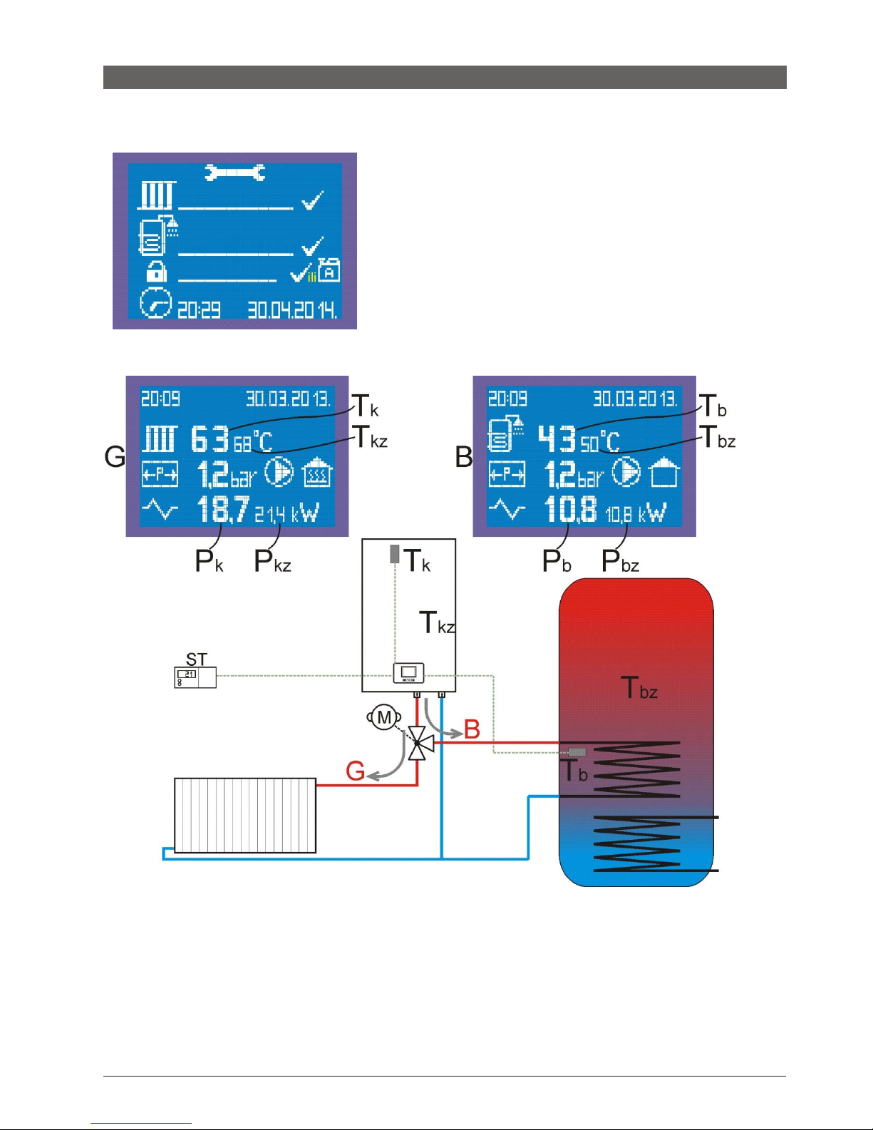
HEATING SWITCHED ON + SANITARY WATER SWITCHED ON SAFETY CHECKED or BIN
- heating has priority, when the room thermostat switches off the sensor of
temperature is in charge in the boiler and if the temperature of the boiler is
lower than the set one, which is reduced by 3˚C, the relay of the boiler is
switched on (the motor valve is switched, which directs the water from the
boiler to the heat exchanger in the boiler), 'b' appears on the display, and if
necessary, relays of the heater switch on or off depending on the temperature.
- when symbol √ is in the safety mode, operation of the boiler is blocked on the
temperature of 3˚C or lower.
- when symbol of bin is in the safety mode (antifreeze mode), there is no
blockade of operation of the boiler regardless of the possible low temperature
of the boiler. Everything else is the same in both cases.
HEATING REGIME
Tkz - The set temperature of the boiler to which the water should be heated in the heating regime
Tk - Current temperature of the boiler in any regime
SANITARY WATER PREPARATION REGIME – BOILER REGIME
Tbz - The set temperature of the boiler to which the water in it should be warmed.
In this regime, the temperature of the boiler to which it needs to heat is calculated as:Tkz = Tbz + 15 C
Tb - Current temperature of the boiler. PUMP WORKS UNTIL Tb = Tbz
Page 36
Setting the operating regime
HEATING REGIME
Tkz - The set temperature of the boiler to be heated in the heating regime
Tk - Current temperature of the boiler in any regime
SANITARY WATER PREPARATION REGIME – BOILER REGIME
Tbz - The set temperature of the boiler to which the water in it should be warmed.
In this regime, the temperature of the boiler to which it needs to heat is calculated as: Tkz = Tbz + 15˚C
Tb - Current temperature of the boiler in any regime
The boiler must reach the Tkz temperature which is calculated according to the above-mentioned formulas and, if
necessary, switch the heaters on or off according to the rules which are already defined. The pump works in this
regime until the current boiler temperature (Tb) reaches the set temperature of the boiler (Tbz).
Check of the set parameters of Heating and Sanitary water preparation
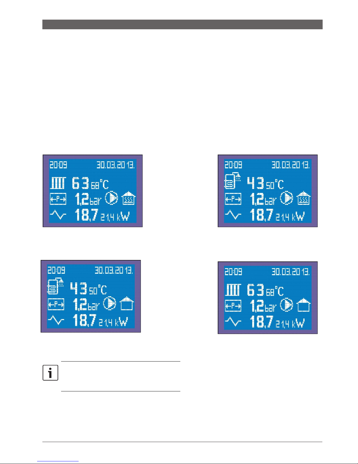
The overview of the
display changes, by
pressing the OK button,
in order to check
parameters which are
set in the sanitary water
regime
→
Overview of the HEATING regime is presented
by the RADIATOR symbol
The set and current
parameters of the
heating system can be
checked by pressing the
OK button, if the device
is in the sanitary water
regime
→
Overview in the HEATING regime is presented by
the BOILER symbol
The changed overview remains on the display
for 15 seconds and after that time it returns to
the basic overview. Another way to change the
overview is to press the OK button.
Page 37

Setting the operating regime
THE SETTING MODE IS ENTERED BY SHORT PRESSING OF THE ‘SET’ BUTTON IN ANY REGIME:
The display shows 'G', the set temperature of heating starts to flash and it can be set in the range of 10 - 80˚C. When it is set by pressing 'OK', it switches to the setting of the following parameter: the set power of heating flashes - after the setting (if
preparation of sanitary water is not activated), if the 'OK' button is pressed, the set heating temperature flashes and thus in
circle. To remember the changes that are made, that is, the new set values and to exit from the setting, the 'SET' button must
be pressed. If the 'SET' button is not pressed within 15 seconds from the last pressing of some of the other buttons, the
processor exits the setting mode and continues to work according to the “old” set values of power and temperature.
The setting is continued after setting the temperature and the power of the heating, if the preparation of sanitary water is
activated as well:
- now, instead of the symbol of radiator, the symbol of boiler appears (overview 'B'). The presented current temperature is the
temperature of the boiler, and the set temperature of the boiler that can be set in the range of 10 - 70˚C starts to flash and it is
taken (increased by 15˚C max. 80˚C) as the temperature to which the boiler is heated while in the sanitary water preparation
regime. If the ‘OK’ button is pressed after setting this temperature, the set power of the boiler for the preparation of the sanitary
water begins to flash, and it should be set taking into account the volume of the boiler, the power of the heat exchanger and the
nominal power of the boiler, that is, choose the optimum power for preparation of hot water in the boiler. To remember the
changes that are made, that is, the new set values and to exit from the setting, the 'SET' button must be pressed. If the 'SET'
button is not pressed within 15 seconds from the last pressing of some of the other buttons, the processor exits the setting mode
and continues to work according to the “old” set values of power and temperature.
Page 38
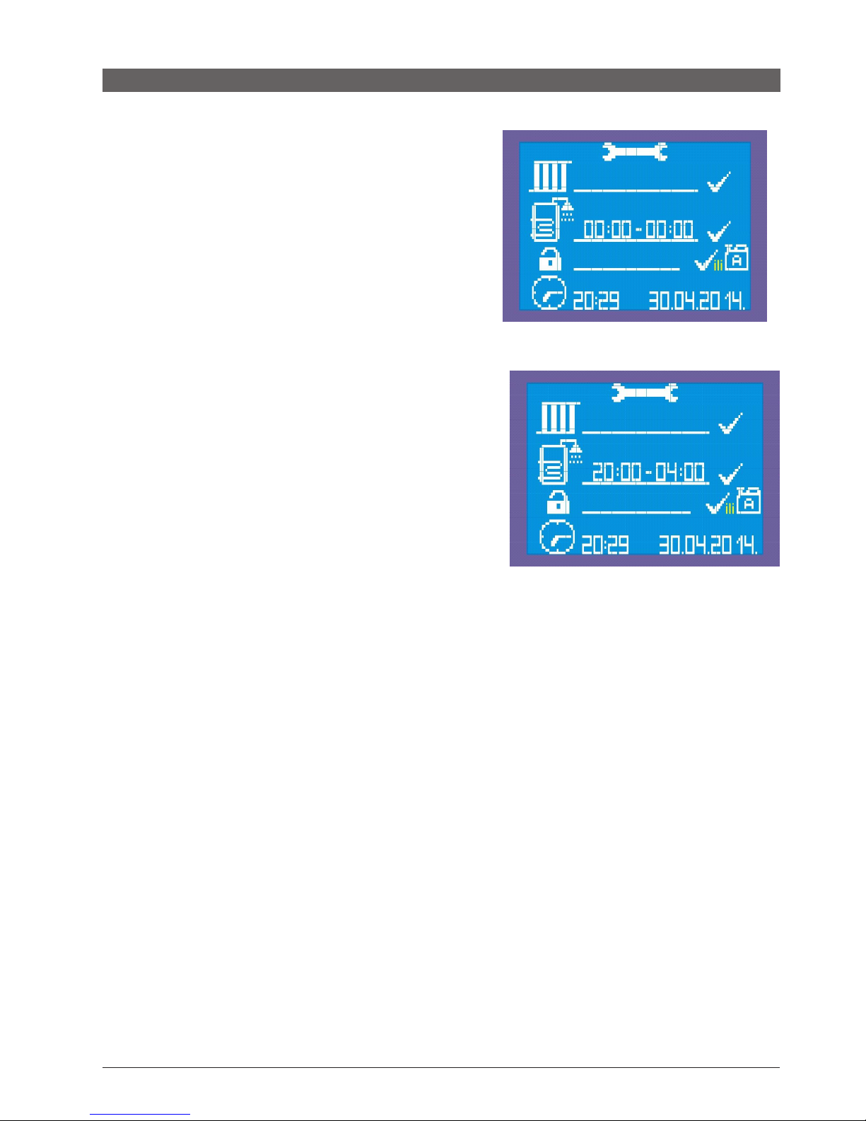
Timer in sanitary water preparation regime
Function of the timer in sanitary water preparation regime
A timer appears on the display next to the symbol of boiler in the setting
mode when the function of sanitary water preparation is enabled. Format
of the timer is 00:00 - 00:00 (24h marking time).
It appears only when the function is CHECKED.
The devices comes as factory-set at 00:00 - 00.00 which means that the
timer allows the preparation of sanitary water throughout the day. If two
times are set, for example: 22:50 - 22:50, the preparation of sanitary
water is still possible throughout the day.
This function is introduced in order to connect the boiler to another
heating system, for example: solar or to solid fuel boiler. It is good then to
set up the preparation of sanitary water in a certain period of time when
there is no sun or when the solid fuel boiler is not charged.
The image shows an example of setting the function of the preparation of
sanitary water for a period of time from 20:00 to 04:00. There is no energy
of the sun in this period, so it is necessary to prepare sanitary water for
use in the evening or in the morning hours.
This setting also allows the preparation of sanitary water in hours of less
expensive electricity.
Setting
When the sanitary water preparation regime is enabled, a timer appears on the display. We go through the setting parameters
by pressing the OK button. Time will start to flash in the following order:
00:00 - 00:00 – hours of switching on are set (for example 20)
20:00 - 00:00 - minutes of switching on are set (for example 30)
20:30 - 00:00 - hours of switching off are set (for example 04)
20:30 - 04:00 - minutes of switching off are set (for example 30)
Means that we set the time to 20:30 - 04:30
Every setting in any regime is confirmed by pressing the SET button.
Page 39
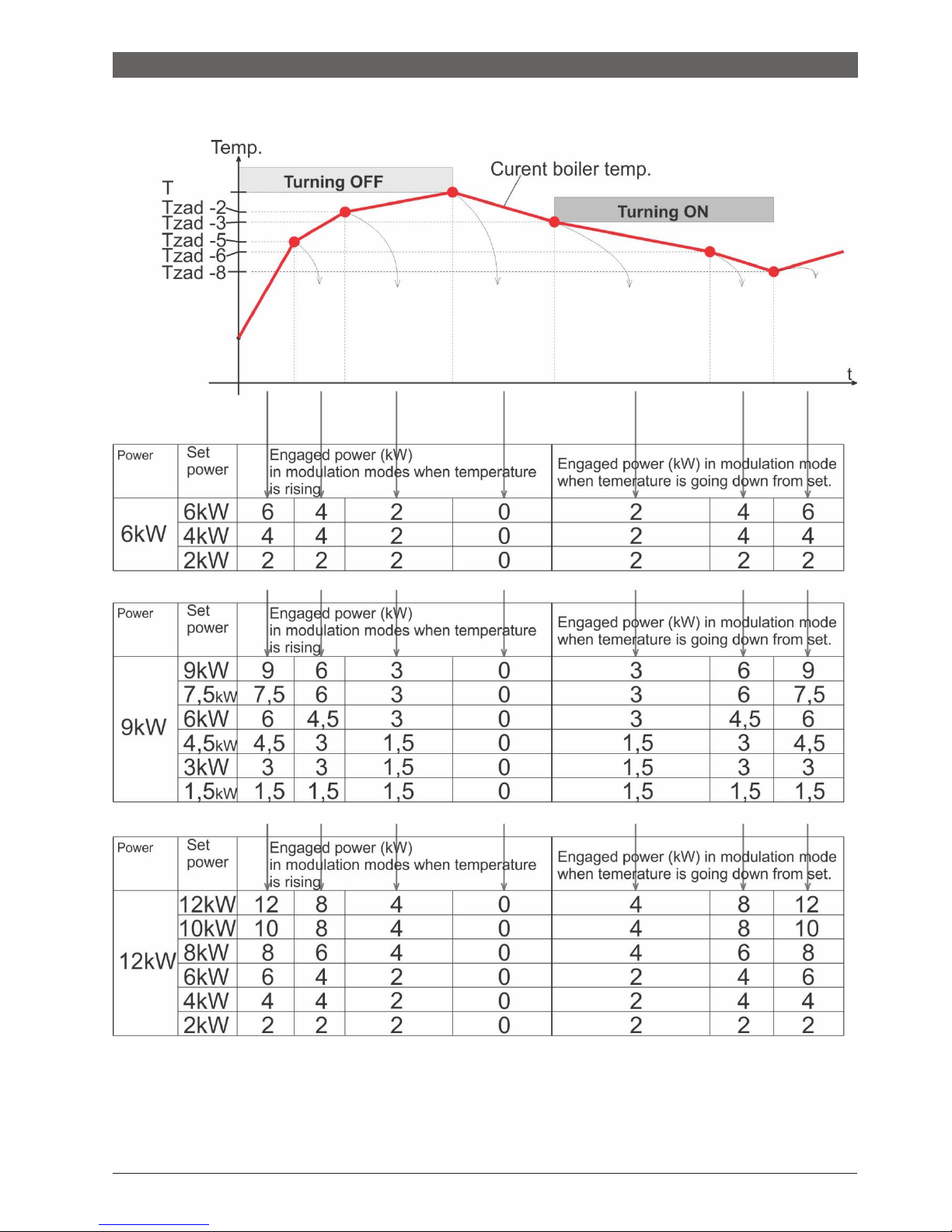
Parameters
Graph and table of Switching heaters on and off in the power mode 6, 9 and 12kW
Note:
when the set power can not be divided into 3 groups, it is divided into 2 groups, (for example, with a boiler with a nominal power
of 6kW and set 4kW, it can only be divided as 2 + 2kW) or, if this is not possible as well, then the complete set power switched
on and off in one degree (for example, with a boiler of nominal power 6kW and set 2kW - it can not be divided into 2 or 3
groups).
Page 40
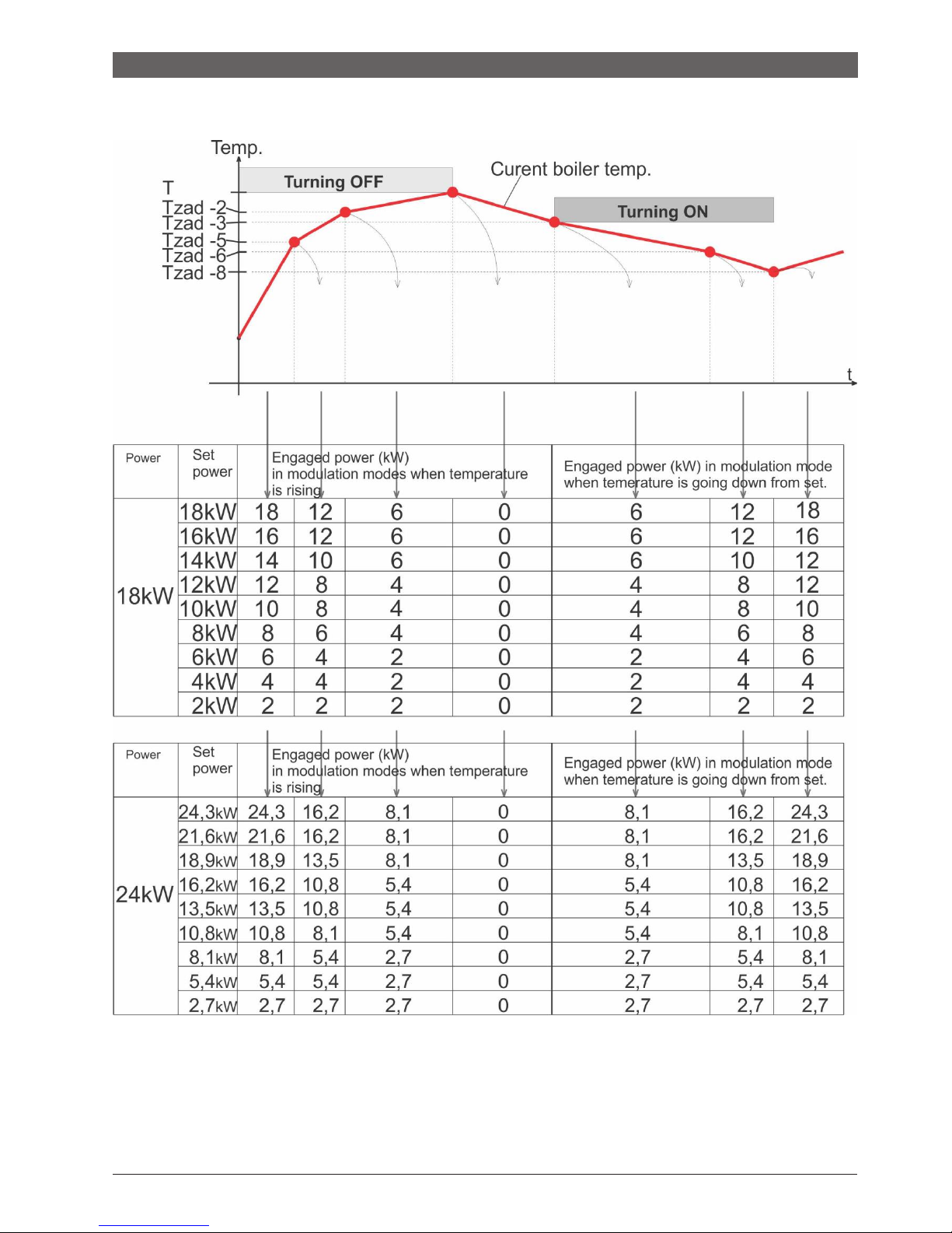
Parameters
Graph and table of Switching heaters on and off in the power mode 18 and 24kW
Note:
The heating group can consist of one heater, or 2, or 3 heaters, depending on the power of the boiler. Also, the heating groups
do not always consist of the same heaters, but are formed from heaters which, at the time of switching on/off, selected by the
microcontroller based on the criteria for the minimum operating time of a particular heater, while respecting the symmetric load
according to phases.
Page 41
CODES
WARNING codes
A0 -
A1 - Warning: approaching the lower limit of the allowed pressure (0.8 bar)
SHOULD BE DONE - Fill the system with water to the necessary pressure
A2 - Warning: approaching the upper limit of the allowed pressure (2.2 bara)
SHOULD BE DONE - Bring the system to the required pressure
A3 - Warning: approaching the lower limit of the allowed temperature (5 degrees) of the HEATING SYSTEM
SHOULD BE DONE - Switch on room thermostat and heaters or activate freezing protection regime
A4 - Warning: approaching the upper limit of the allowed temperature (80 degrees) of the HEATING SYSTEM
SHOULD BE DONE - Lower the power of the boiler, check whether the valves are open
ERROR codes
E0 - Error: the set parameters are not within limits (this is practically impossible
unless the eeprom is empty and the device is switched on for the first time) - all switched off
E1 - Error: reached lower limit of the allowed pressure (0.3 bar) – all switched off
REMEDY – Fill the system with water to the necessary pressure, check the sealing of all connections
E2 - Error: reached upper limit of the allowed pressure (2.6 bar) - all switched off
REMEDY - Bring the system to the required pressure by discharging air and water when needed
E3 - Error: reached lower limit of the allowed temperature (3˚C) - all switched off
E4 - Error: reached upper limit of the allowed temperature (85˚C) – the pump is switched on continuously
REMEDY - Switch off the main fuses for powering the boiler with electricity, call the service center
E5 - Error: reached lower limit of the allowed temperature of the BOILER (3˚C) - INFORMATIVE
E6 - Error: sensor of temperature of the boiler in break or short circuit - all switched off
REMEDY - Switch off the main fuses for powering the boiler with electricity, call the service center
E7 - Error: sensor of temperature of the boiler in break or short circuit – no sanitary water preparation
REMEDY - call the service center
E8 - Error: sensor of pressure in break or short circuit – all switched off
REMEDY - Switch off the main fuses for powering the boiler with electricity, call the service center
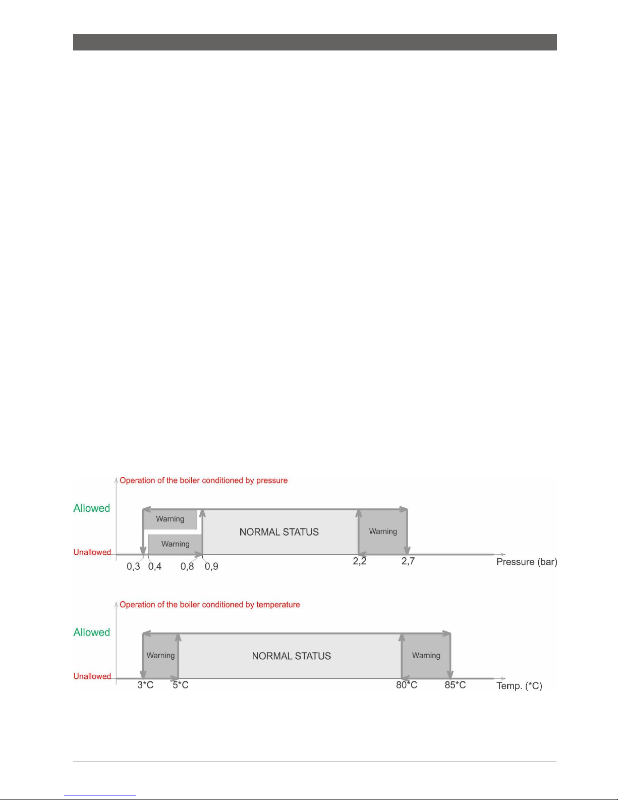
Graphical overview of operation of the device
based on pressure and temperature
Page 42
Cleaning and maintenanace
8
Cleaning and maintenance
8.1 Cleaning the boiler
DANGER: Life danger from
electric shock!
Clean the device on the outside
by a damp cloth.
You can perform electrical works
only if you have
8.2
appropriate qualification
.
Before opening the device: disconnect the
heating system from the power supply
by using the safety switch of the heating
system and disconnect it from the main
networkby using an appropriate fuse.
Secure the heating installation from
involuntary switching on
.
Comply with the regulations for installation.
WARNING:
Material damages caused by
unprofessional maintenance
!
Insufficient
or unprofessional maintenance of
Check the operating pressure, fill with
water and discharge air from the
installation
DANGER: Danger to health due to mixing
drinking water!
Be sure to comply with national regulations and
norms for avoiding the mixing of drinking water
(eg. with water from heating installations).
comply with EN
1717.
Establish the operating pressure of at least 1
bar,
depending on the height of the
installation.
the boiler can lead to damages or destruction
of the boiler, and thus to
loss of warranty right.
Ensure regular, thorough and professional
maintenance of the heating installation.
Protect electrical parts and operating units from
water and moisture.
Use only original spare parts of the manufacturer or
spare parts that are approved by the manufacturer.
No
liability is assumed for damages arising from spare
parts which are not supplied by the manufacturer.
The inspection and maintenance record is
on page 30.
Perform all works according to the inspection and
maintenance record.
Deficiencies need to be repaired immediately.
The volume of newly filled water decreases in the first days after the filling due
to heating.
This creates airbags that create interference in the
heating system.
Inspection of operating pressure
The operating pressure of the new heating installation should
be controlled on a daily basis in the beginning.
If necessary,
add water to the heating system and discharge the air.
After that, check the operating pressure once a month.
If
necessary, add water and discharge air from the heating
system.
Check the operating pressure. If the pressure of
installation drops below 1 bar, it is necessary to fill it with
water.
Add water
.
Discharge air from the heating instalation
.
Check again the operating pressure
.
Page 43
Cleaning and maintenance
8.3 Discharge air from the installation
and fill it with water
WARNING:
Material damages caused by heat
straining. Filling the heating installation in a warm
state can cause cracks due to tension.
Fill the heating installation in cold state
only (temperatur
e of the starting line
maximum 40
°C).
WARNING:
Material damages caused by
frequent filling
!
Due to frequent filling of heating installation with
water,
it can be damaged
by corrosion or by
formation of limescale, depending on the
properties of water.
Inspect the heating installation for
impermeability, and the expansion
container for functionality.
Connect the hose to the water tap
.
Fill the hose with water and attach to the hose
connector of the tap for charging and discharging.
Fasten the hose with the clout of the hose and
open the charging and discharging tap.
Fill the heating installation slowly and monitor
the
overview of pressure (ma
nometer)
.
Discharge the air during the filling process
.
Close the discharging tap when the operating pressure is reached.
Water must be refilled
when the operating pressure
drops due to discharging of air.
Remove the hose from the charging and discharging tap.
Page 44
Cleaning and maintenance
8.4 Record on inspection and
maintenance
Perform maintenance at least once a year, or
when the inspection shows
the state of
installation that requires maintenance.
The record on putting into operation, inspections and
maintenance serves as an attachment for copying.
The performed inspections should be verified by signature and
date.
Inspection and maintenance works according to need
Page
Date: ______
Date: ______
Date: ______
1.
Check the condition of installation
2. Perform visual and functional inspection
4.
Establishing operating pressure
•
Examine the pre-pressure of expansion container
•
Operating pressure is set to
•
Discharging air from the heating installation.
•
Check of the safety valve for heating
5.
Clean the water filter
6.
Check for damages to electrical lines
7.
Check whether the electrical connectors for
operating the boiler and the used elements stand
firmly, and tighten them if necessary.
8.
Check the functions of the thermostatic regulator on the
boiler
9. Check the function of
safety parts
10.
Check the function of the remote control
11.
Check the insulation of the rod heaters
12. Check the function of connector for grounding
13.
Check the isolation of the electrical switchboard
14. Check the function of the pump for heating
15.
Make a final control of the inspection works and
document the results of the measurement and testing
16.
Confirmation of a professionally conducted inspection
Seal / Signature
Seal / Signature
Seal / Signature
Table: Record on inspection and maintenance
Page 45

Environmental protection / disposal into waste
9
Environmental protection /
disposal into waste
Environmental protection is one of the basic principles of business.
Product quality, cost-effectiveness and environmental protection represent
equally worthwhile goals.
It is necessary to strictly comply with the laws and regulations
on environmental protection. We use only the best
technique and materials for the purpose of protecting the
environment and respecting economic principles.
Packaging
When packing, we comply with recycling systems that are specific
in certain countries and which ensure optimum recycling.
All used
packaging materials do not harm the environment and can be
recycled.
Old devices
Old devices contain valuable recyclable materials. The
assemblies can easily be separated and the plastic
materials are marked. In this way, the assemblies can be
sorted and taken for recycling, that is, disposal.
Page 46
Faults and their remedy
10 Faults and their remedy
Remedy of faults on
the regulation and
hydraulics must be carried out by an
authorized company.
Use only original parts for repairs.
fault
: description
:
cause
:
measure
:
The boiler does not
react after switching on
the main switch
The display does not
respond, the other
components do not
working
- boiler is disconnected from electricity
- the fuses on the bottom panel are
switched off
-
possible disappearance of the control
phase
- fault of the main switch ON / OFF
-
Ensure power supply voltage
- switch on the fuses
- check on the fuses if there are all
three phases at the exit
- Replace the defective part
The boiler does not heat
or does not heat
enough / the heating
pump works
Everything on the
display is in the
recommended limits,
but the boiler does not
deliver hot water
- Lack of 1 or 2 phases
- The power of the boiler is too low
-
Fault in one of the relays
- Fault in one of the heaters
- Check if all three phases come into
the boiler
- Check the set power of the boiler.
- Replace the defective part
- Replace the defective part
The boiler heats but it is
very noisy
Increased noise level
during operation
- Air in the system
- Too low water flow
- Possible occurrence of
limescale on the heater
-
Check if the air is discharged
from the system and
discharge it
- Check the valves below the boiler
and open them.
-
Clean the filter in front of the boiler
-
Remove heaters and clean them
(this is not considered as a
complaint within the warranty period)
The boiler is quickly
switching off
It reaches the desired
temperature too quickly
and stops working
- Closed valves under the boiler
-
The pump’s fuse has stopped working
- Stuck pump
- Defective pump
-
Open the valves
- Replace the defective part
- Start the rotor of the pump
- Replace the defective part
Large oscillations of the
operating pressure
Too fast and too large
changes in the
operating pressure
- One valve is closed
- Pressure in the expansion
container is inadequate
- Defective container
-
Open the valve
- Check the pressure
in the
expansion container and pump
the container to an adequate
value if it is necessary
- Replace the defective part
Page 47
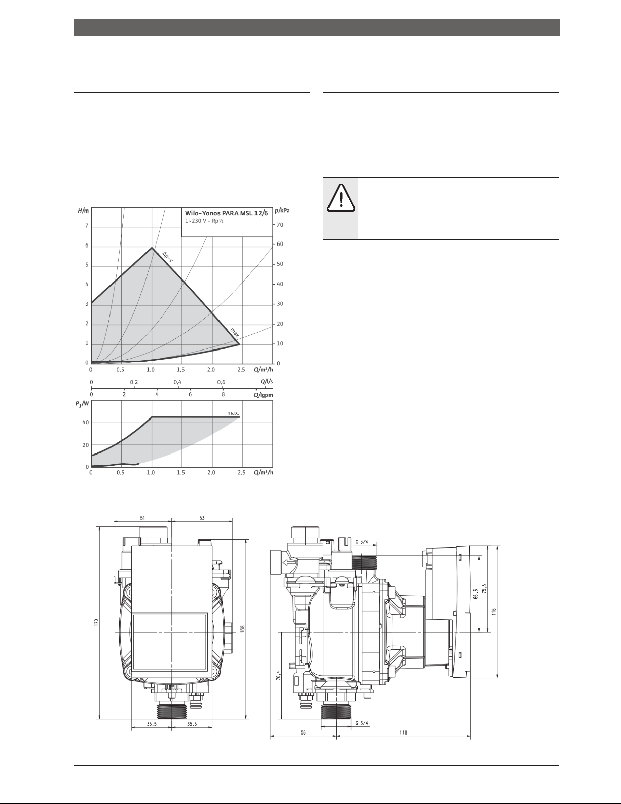
Instructions for designing
11. Instructions for designing of pump WILO Yonos Para full Erp
11.1 Total height of the water column
of the heating pump
11.2 The systems on which the Compact
ePlus boiler can be connected
The total height of the water column of the internal heating
pump is shown in the following diagram with the respective
upper and lower limit values.
Characteristics of the heating pump
- All systems for space heating that are designed to
80/60 temperature regime (or lower)
- Closed heating systems
.
- Systems where there exists a solid fuel boiler
YONOS PARA
ATTENTION! : When connecting the boiler
to such as system, it is obligatory
to take
care that both pumps in the system push
water in the same direction so that the
flows do not collide.
Possible too high
hydraulic straining of the system
and
breaking of some components as well.
Technical drawing by WILO Intec Gmbh
- It can be used as a device for heating sanitary water in
accumulation boilers through an exchanger.
- It may also be used in certain technological processes provided
that there is no need for water temperature over 60 °
It must not be used for direct heating of sanitary wate
060526
Page 48

 Loading...