

Page 1
RS70 manual GB 2009 www.flexiforce.com
1
manual
GB
rev.0 Feb-09
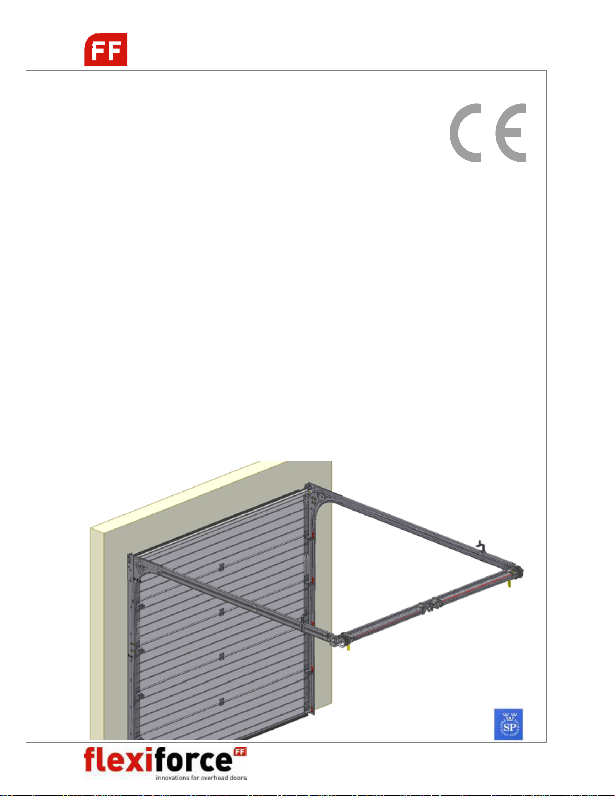
RS70
Hardware system for
residential (garage)
overhead doors
Built-in height 86mm, springs in rear
INSTALLATION / MAINTENANCE / USAGE
© All rights reserved. FlexiForce® 2009
Page 2
RS70 manual GB 2009 www.flexiforce.com
2
manual
GB
rev.0 Feb-09
ATTENTION! GENERAL WARNING!
To install, use and maintain this door system safely, a number of precautions
must be taken. For the safety of all concerned, pay heed to the warnings and
instructions given below! If in doubt, contact your supplier.
SPECIAL SAFETY WARNINGS OR REMARKS IN THIS MANUAL ARE INDICATED
WITH THIS SYMBOL. READ THESE WARNINGS CAREFULLY!
This manual has been written for use by experienced fitters and as such is not suitable for
d.i.y. purposes or for use by trainee fitters.
This manual describes the installation of the hardware set components, door sections
(panels) and refers to installation manuals of the electrical operator. Be sure to
supplement this manual if needed with instructions for any additional components not
described in this manual.
Before starting, read this manual carefully!
Certain components may be sharp or have jagged edges. As such you are advised to wear
safety gloves.
All the components which have been supplied are designed for use with this specific
overhead door. Replacement or adding additional components may have an adverse effect
on the safety of, and the guarantee on, the door. Also the CE-approval which has been
granted to this door will be cancelled when components are changed or installation is not
done according to this manual! Installer is responsible for this.
Ensure that there is sufficient light during installation. Remove obstacles and dirt. Make
sure that there is no one else present other than the fitters. Other people (children!) may
get in the way or endanger themselves during the installation.
GUARANTEE, CONDITIONS AND TERMS
The general terms and conditions of delivery and payment issued by the Metaalunie and designated as
METAALUNIE CONDITIONS are fully applicable to all our quotations, contracts and their
implementation. We expressly reject all other terms and conditions. On request we will send you a copy
of these terms and conditions free of charge. A copy may also be downloaded from our website
www.flexiforce.com
.
FlexiForce strives to deliver 100 % in conformance with the order. In practice, in spite of all our controls,
this is not always possible. However we will rectify any errors as quickly as possible, in order to minimise
the inconvenience caused to you or the user. As such, it is important that you inform us as soon as possible
about any problem with the delivery (include the order number and week of production) and give us the
opportunity to offer a suitable solution.
FlexiForce will only reimburse third party costs if we have given explicit permission for this in advance. The
reimbursement is based on normal rates and travelling expenses over distances of 1 hour away at most.
For large-scale projects we strongly advise you to first install 1 door completely before installing the other
doors. In this way, any errors can be detected early on and rectified comparatively cheaply.
This manual does not confer any rights. Technical modifications may be made without written notice.
FlexiForce has endeavoured to design and put together this hardware set in conformance with the
applicable CE-norms. However, we recommend to check our configuration against any local national
specification.
Page 3
RS70 manual GB 2009 www.flexiforce.com
3
manual
GB
rev.0 Feb-09
FlexiForce has applied the mandated INITIAL TYPE TESTING for doors described in this manual, at the
SP-Institute in Sweden (as Notified Body Nr. 0402). The INITIAL TYPE TESTING REPORT that has been
rewarded, can be transferred to the door producing company. This is needed to complete your CE files
according to product standard EN13241-1. Contact FlexiForce for acquiring this report.
APPLICATION RANGE
FlexiForce has developed a new hardware system for garage overhead doors. The system includes the
following features:
• Suitable for single and double garages, Wmax = 5.000 mm, Hmax = 3.000 mm.
• The horizontal track set is standard reinforced with side plate RX560L/R with pulley system
• Advised max door weight is 165 kg. Each spring break device is approved to 125kg.
• CE approved when selecting the proper FlexiForce components.
We wish you every success with the installation of this hardware set. If anything is unclear or should
you have queries, you should of course contact Flexi-Force B.V. or your supplier.
This set has to be completed with the assembled door sections. Panels brands and types according to
the list of approved panels.
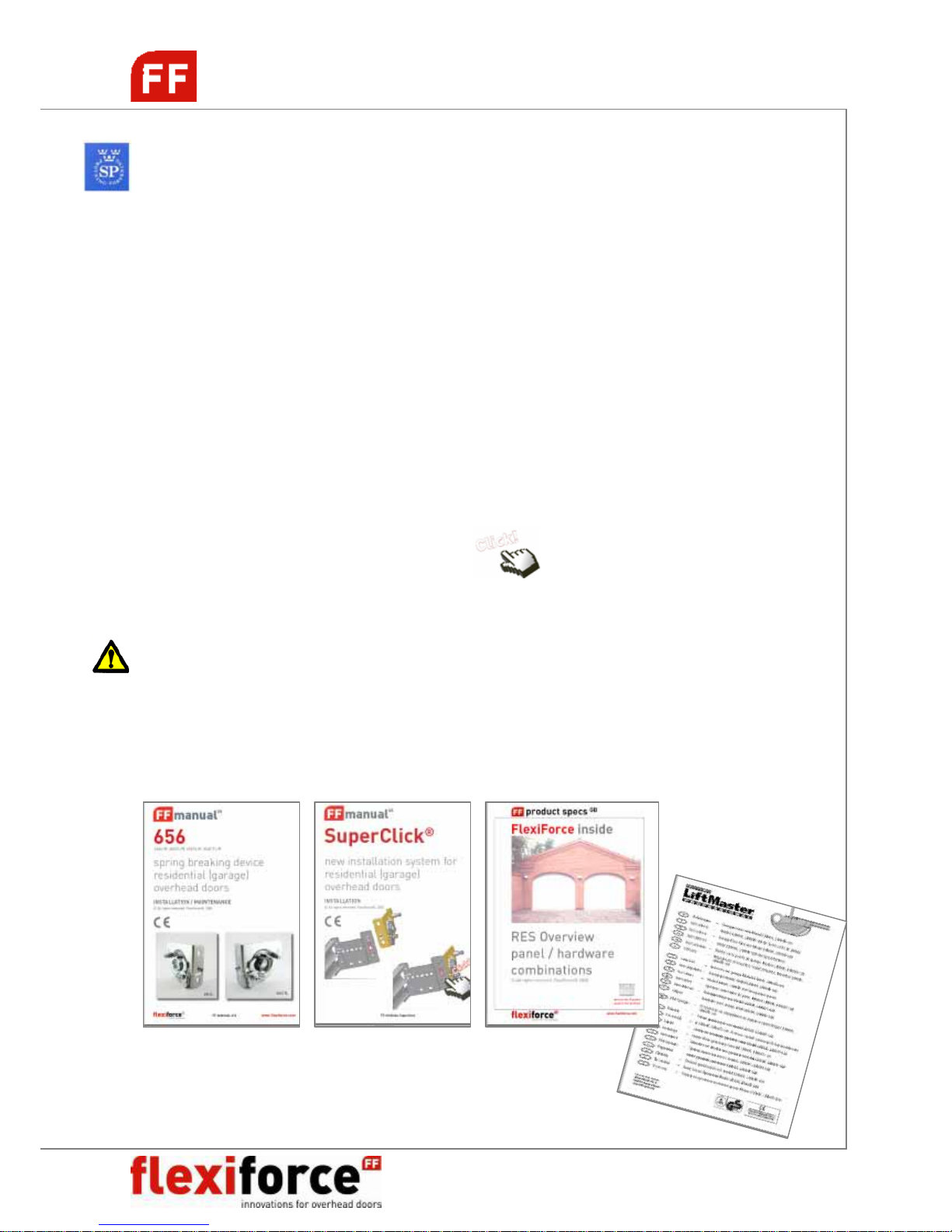
NB! FlexiForce has introduced a new system for shaft installation, so called SUPERCLICK®.
There is a separate manual available for this system (attachment). In this manual, the
SuperClick® system is marked with this sign:
NB! FlexiForce recommends to apply our “light” hardware range for garage doors. In this manual
only “light” components are selected.
Attention! In this set, the fixing material required to install the track set to the building is not
included. It is the responsibility of the qualified door installer to make sure that the building
(stone, concrete, wood, etc.) is strong enough at the points of fixation to ensure a reliable
construction. The door installer has to select proper fixing materials.
RECOMMENDED ADDITIONAL MANUALS
Page 4
RS70 manual GB 2009 www.flexiforce.com
4
manual
GB
rev.0 Feb-09
IN THIS MANUAL:
- Attention, general warnings 2
- Guarantee, terms and conditions 2
-
Application range 3
-
Recommended additional manuals 3
-
Tools for correct and rapid assembly 5
-
Applied fixation materials 5
-
RS70 System overview 6
-
Installing vertical track system 7
-
Installing horizontal track system 8
-
Shaft system installation 11
-
Panel <> Hardware installation 14
-
Cables & Torsion springs 17
-
Finishing the door 19
-
Optional: E-operation 23
-
Panel assembly 24
-
Troubleshooting 27
-
Dismantling the overhead door 28
-
Maintenance and replacement of parts 29
Page 5
RS70 manual GB 2009 www.flexiforce.com
5
manual
GB
rev.0 Feb-09
TOOLS FOR CORRECT AND RAPID ASSEMBLY
(Battery) drill with Bit 4,0 mm
Bit 4,5 mm
Bit 6,5 mm
Plug 10 mm
Plug 13 mm
Hexagonal key 4 mm
Socket screw spanner 8mm (in)
Ring /open ended spanner 10 mm
Ring /open ended spanner 13 mm
Ring /open ended spanner 15 mm
Ring /open ended spanner 17 mm
Socket wrench with ¼” square
Wrench
Gluing clamp
Cord
Water level (hose)
2 blocks of ca. 20 en 40mm in height
Measuring equipment
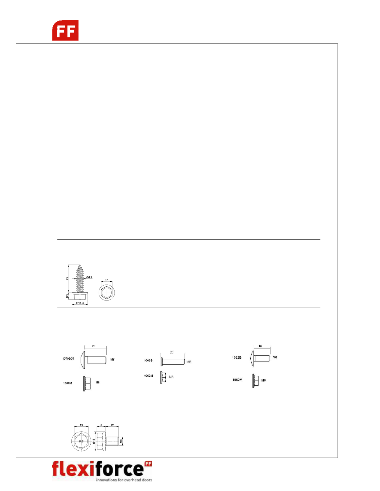
APPLIED FIXATION MATERIALS
The applicable fixation material is described in the drawings of this manuals. Below an overview
of the applied fasteners and optional alternatives.
1055BV, self-tapping screw Alternatives: 1055D, screw, 6,3x25mm, with drill-point
Max torque 10Nm, key 10 1053BV, screw 6,3x35mm
1053D, screw 6,3x35mm, with drill-point
1054-25, 1054-35, screw with socket hex cap, drill point
1054W-25, 1054W-35, screw with socket hex cap (RAL9010)
Optional: 1055CAP10, white (RAL9010) cover for screws (key 10)
1070B35, bolt M8x25 1006B, press bolt 1062B, bolt M6x16
1068M, nut M8 1062M, nut M6 1062M, nut M6
Max. torque 13Nm, key 13 Max. torque 9,1Nm, key 10 Max. torque 5,3Nm, key 10
1071BC, bolt M8x12, SuperClick® secure bolt NB! Fixation material for installing to wall and
Max. torque 10Nm, key 13 ceiling is not included in this manual!
Page 6
RS70 manual GB 2009 www.flexiforce.com
6
manual
GB
rev.0 Feb-09
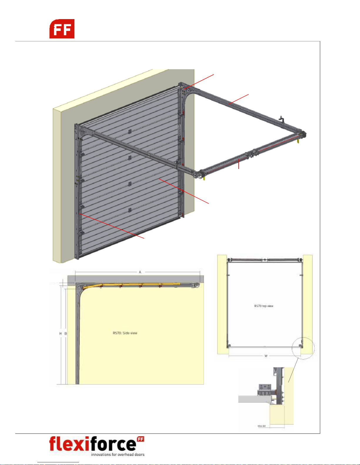
RS70 SYSTEM OVERVIEW
B = H – 70mm for manual operated doors
B = H – 0mm for e-operated doors (NB! See Chapter E-operation!!!)
Shaft system
with torsion springs, spring break devices
drums, spring fittings, cables, etc.
RS70H10etc.
Horizontal double track set
RSV10etc
Vertical set with track, side seal and
vertical angle
Door panels, sections
With end caps, hinges, bottom
brackets, bottom astragal and seal,
top roller carriers, windows, etc.
Pulley system
Leading the cables to the drums at
the rear end of the horizontal
double track
Min 86
Page 7
RS70 manual GB 2009 www.flexiforce.com
7
manual
GB
rev.0 Feb-09
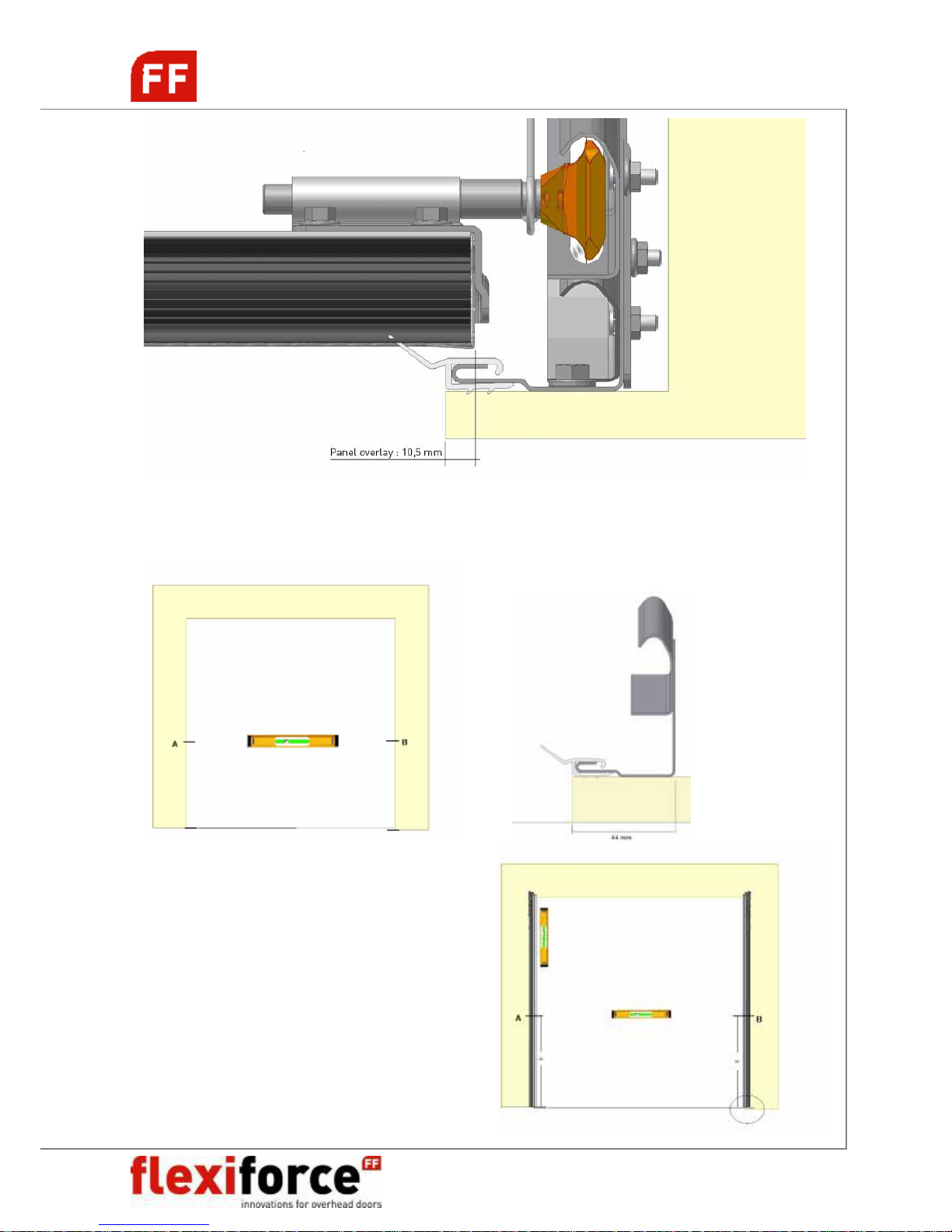
INSTALLING VERTICAL TRACK SYSTEM
Page 8
RS70 manual GB 2009 www.flexiforce.com
8
manual
GB
rev.0 Feb-09
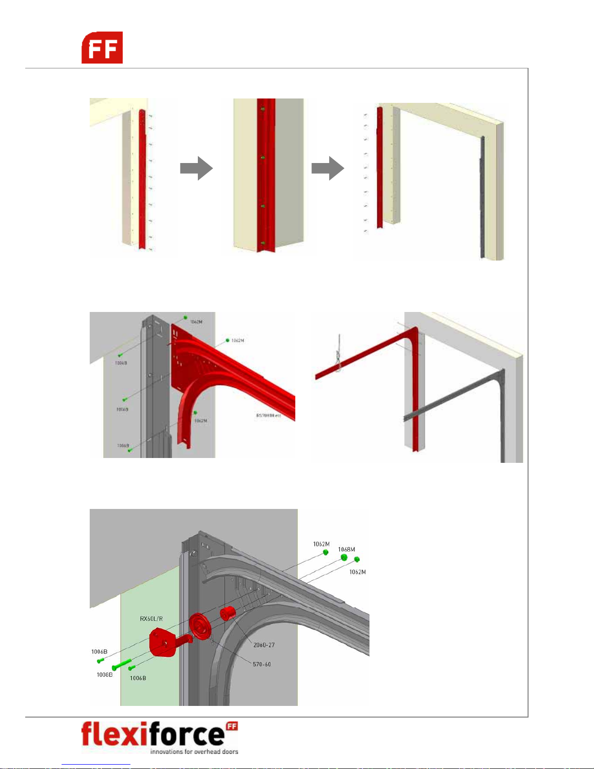
VERTICAL TRACK SET
HORIZONTAL TRACK SET
PULLEY SYSTEM INSTALLATION
NB! Optional installation of RX80L/R
and 570-80 pulley.
Page 9
RS70 manual GB 2009 www.flexiforce.com
9
manual
GB
rev.0 Feb-09
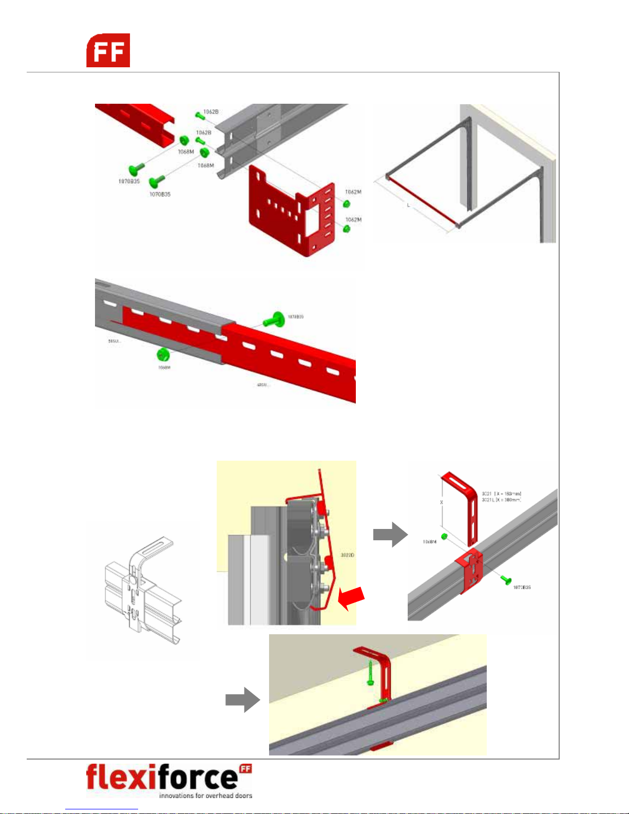
CONNECTION HORIZONTAL TRACKS
L = days opening width + 134mm
SUSPENSION HORIZONTAL TRACK TO CEILING
CLICK!
Page 10
RS70 manual GB 2009 www.flexiforce.com
10
manual
GB
rev.0 Feb-09
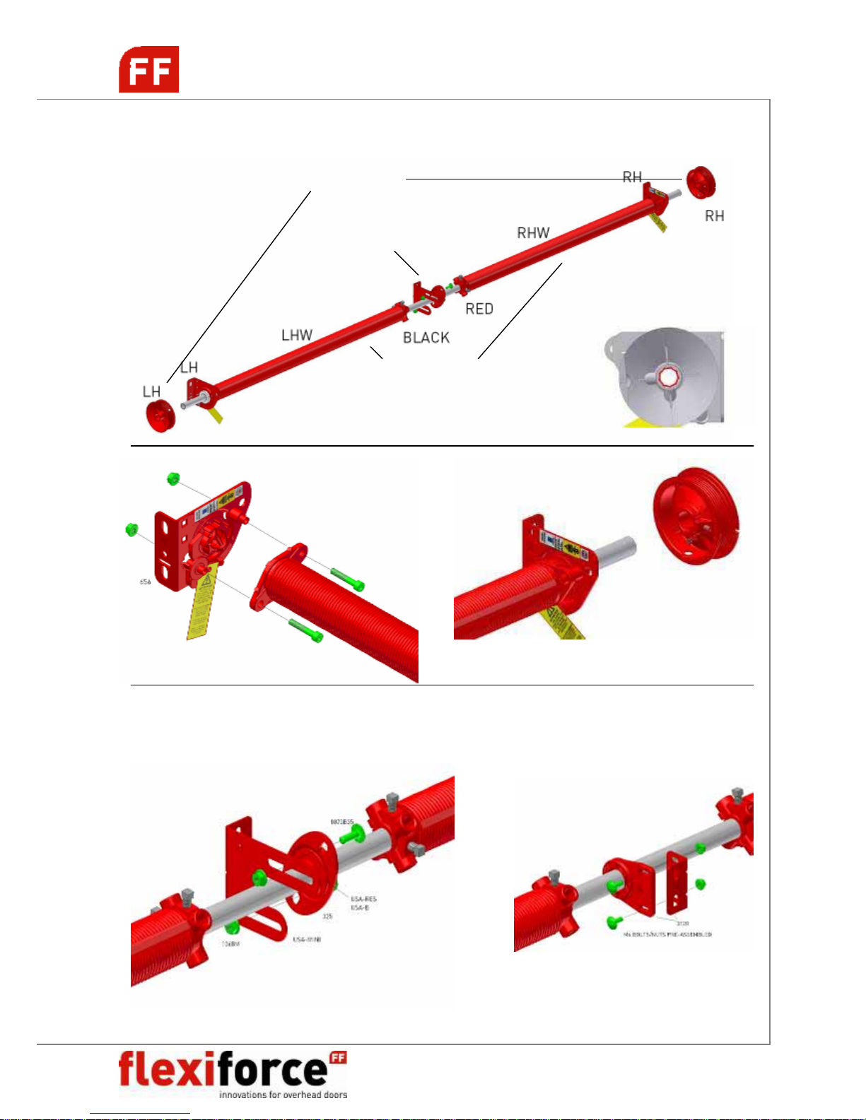
SHAFT SYSTEM INSTALLATION
DOOR W<3000mm
CENTRAL SHAFT SUSPENSION (2 ALTERNATIVES)
USA-MINI 312R
Central shaft suspension
Torsion springs
with spring fittings and spring break devices
Cable drums
No key-way: FF4X8, FF400-8(S), FF0402
Without key-way
tube shaft
Page 11
RS70 manual GB 2009 www.flexiforce.com
11
manual
GB
rev.0 Feb-09
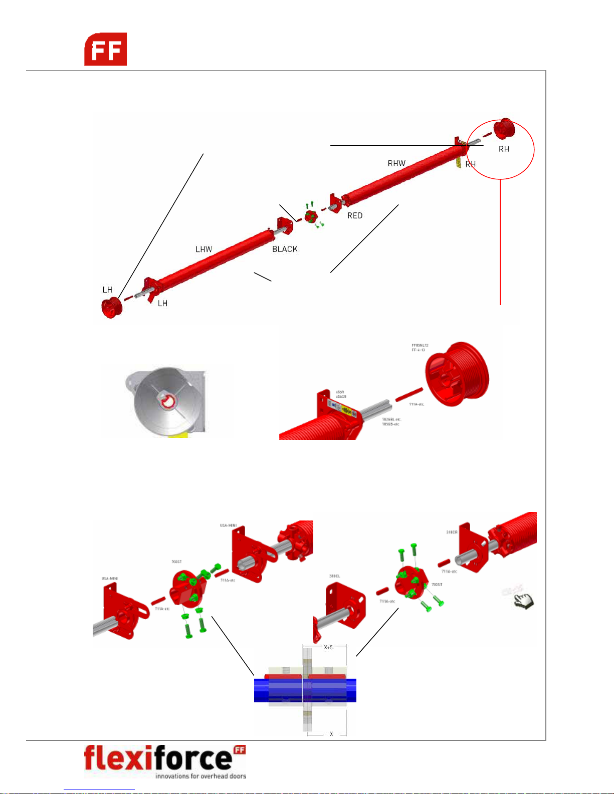
SHAFT SYSTEM INSTALLATION
DOOR W>3000mm (double doors)
CENTRAL SHAFT SUSPENSION (W>3000mm)
Traditional installation SuperClick® installation
Torsion springs
with spring fittings and spring break devices
Cable drums
With key-way: FF-4-13, FF05NL12 etc.
Central shaft suspension
With coupler and 2 bearing plates
(310CL/CR or USA-MINI)
With key-way
tube key-wayed shaft
Max 23 Nm
Page 12
RS70 manual GB 2009 www.flexiforce.com
12
manual
GB
rev.0 Feb-09
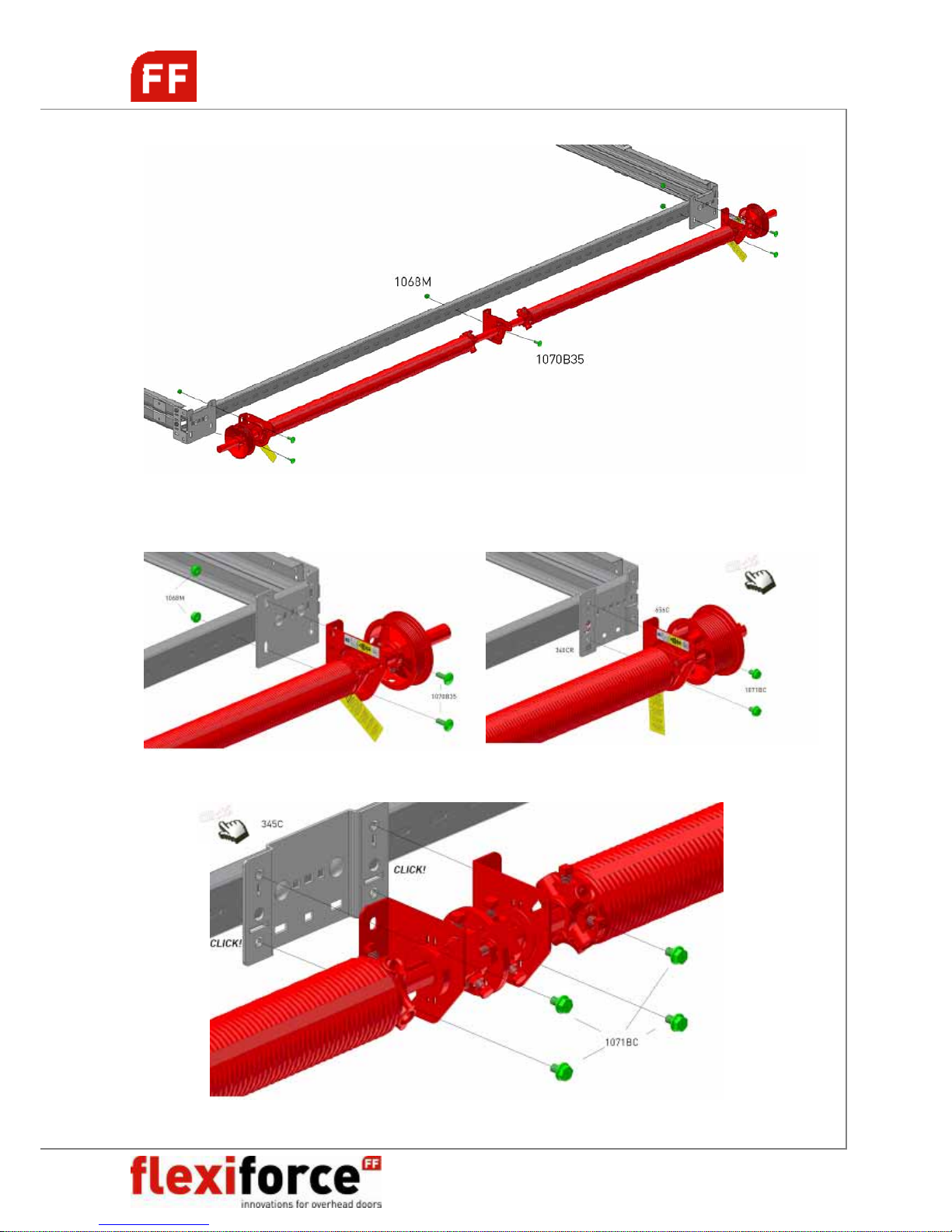
FIXATION TO TRACKS
Traditional installation SuperClick® installation
Page 13
RS70 manual GB 2009 www.flexiforce.com
13
manual
GB
rev.0 Feb-09
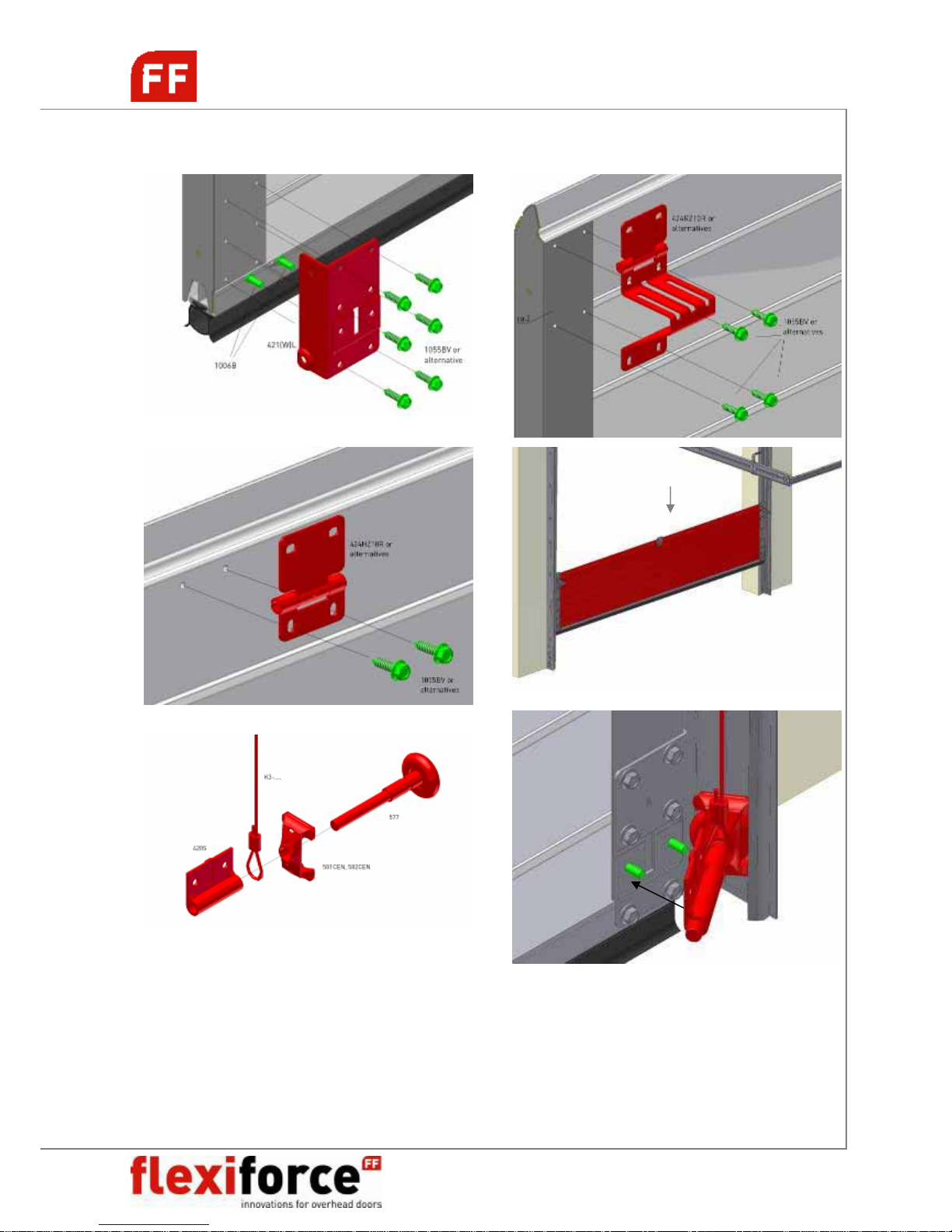
PANEL <> HARDWARE INSTALLATION
Page 14
RS70 manual GB 2009 www.flexiforce.com
14
manual
GB
rev.0 Feb-09
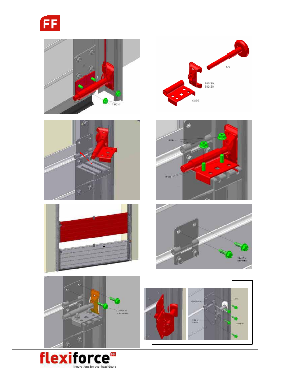
Alternative hinges: 411-series
Page 15
RS70 manual GB 2009 www.flexiforce.com
15
manual
GB
rev.0 Feb-09
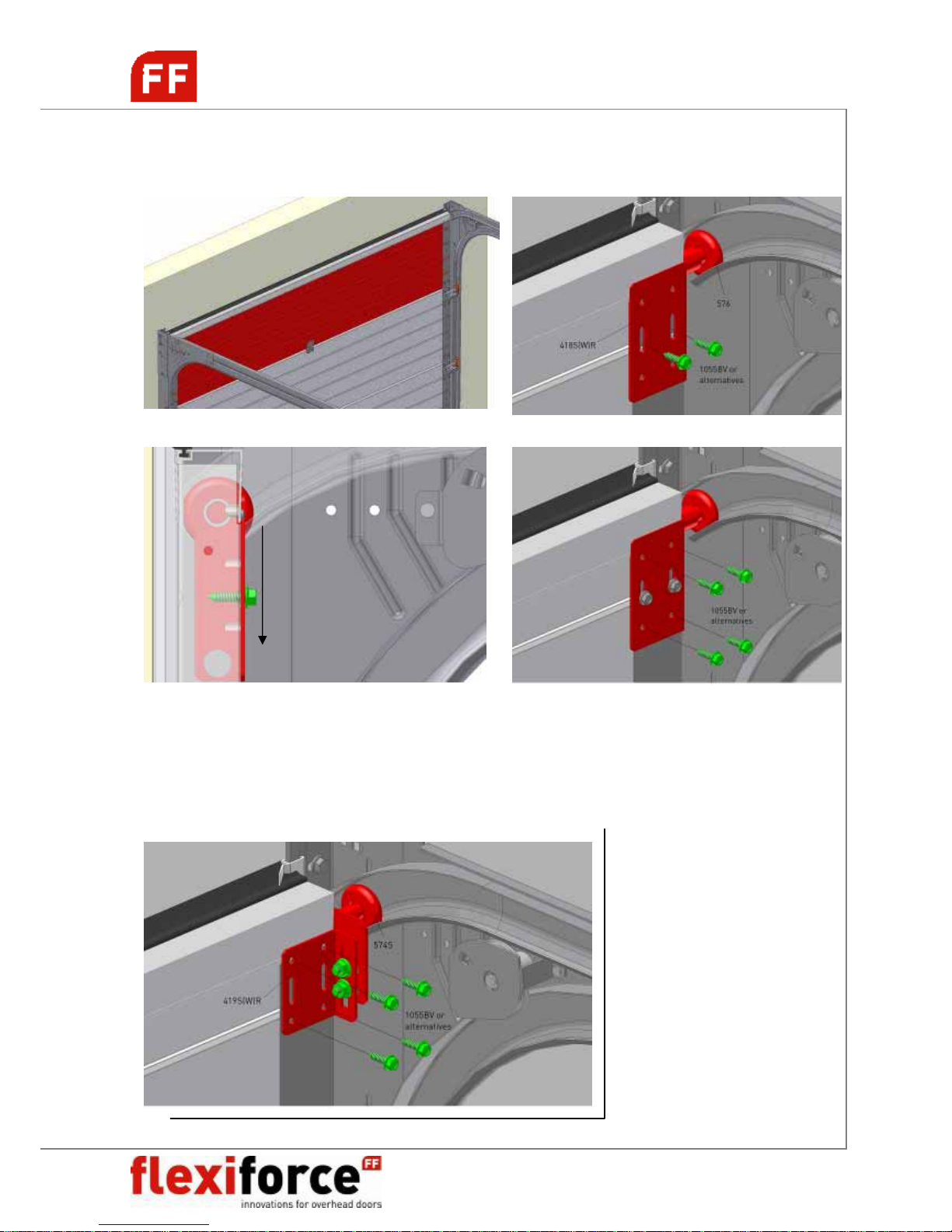
INSTALLATION TOP PANEL / TOP ROLLER CARRIER
Close the door and secure the door panel. Loosen the two self-tapping screws (1055BV) securing the
top roller holder (418SL/R) so that it can be displaced with a slight tick. Press the top panel against
the side (upper) seal and slide the top roller holder as far as possible downwards and fix all screws.
(minimum play between door panel and seal). The bearing roller lies snugly in the rounding of the
bearing tracks.
Alternative top roller carrier: adjustable 419S-series
Page 16
RS70 manual GB 2009 www.flexiforce.com
16
manual
GB
rev.0 Feb-09
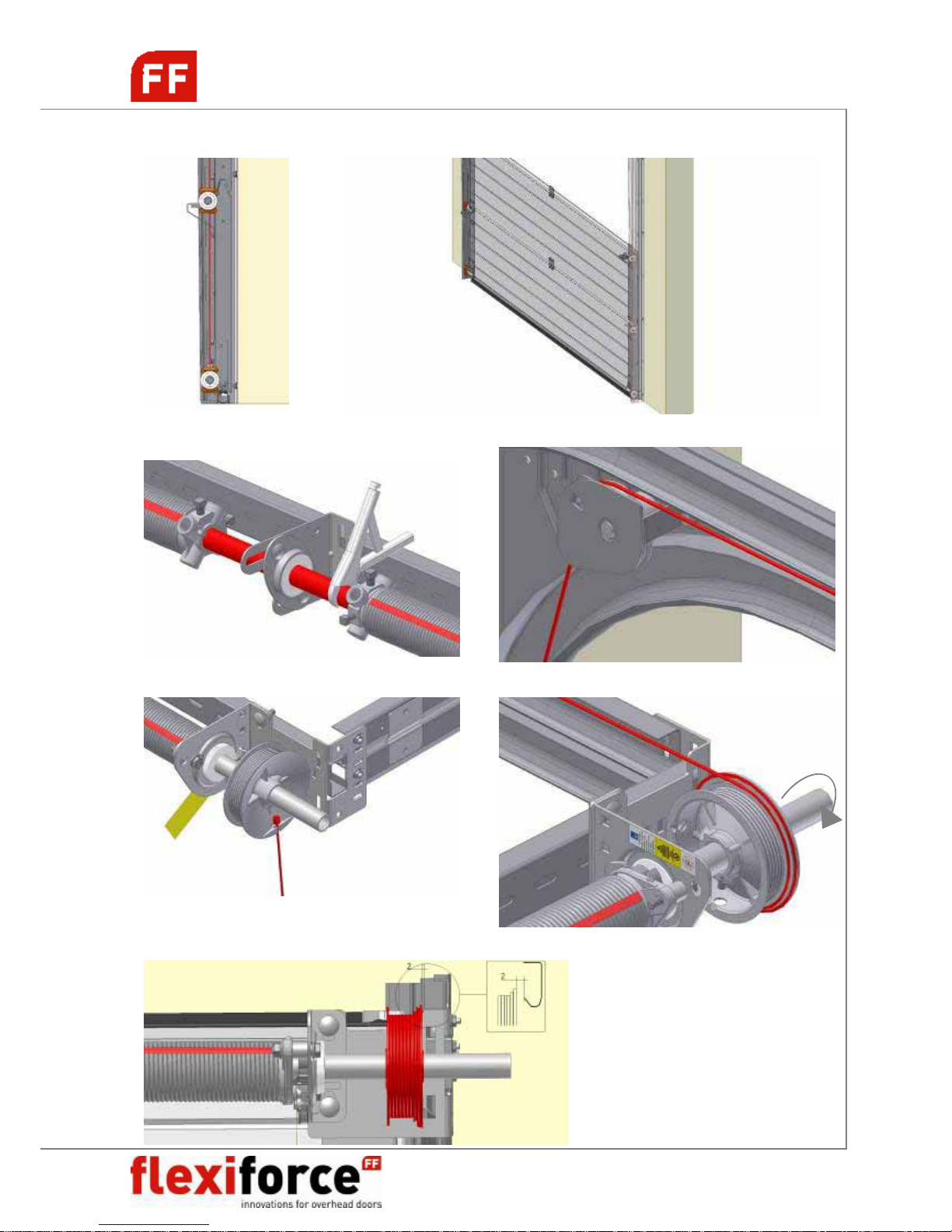
CABLES & TORSION SPRINGS
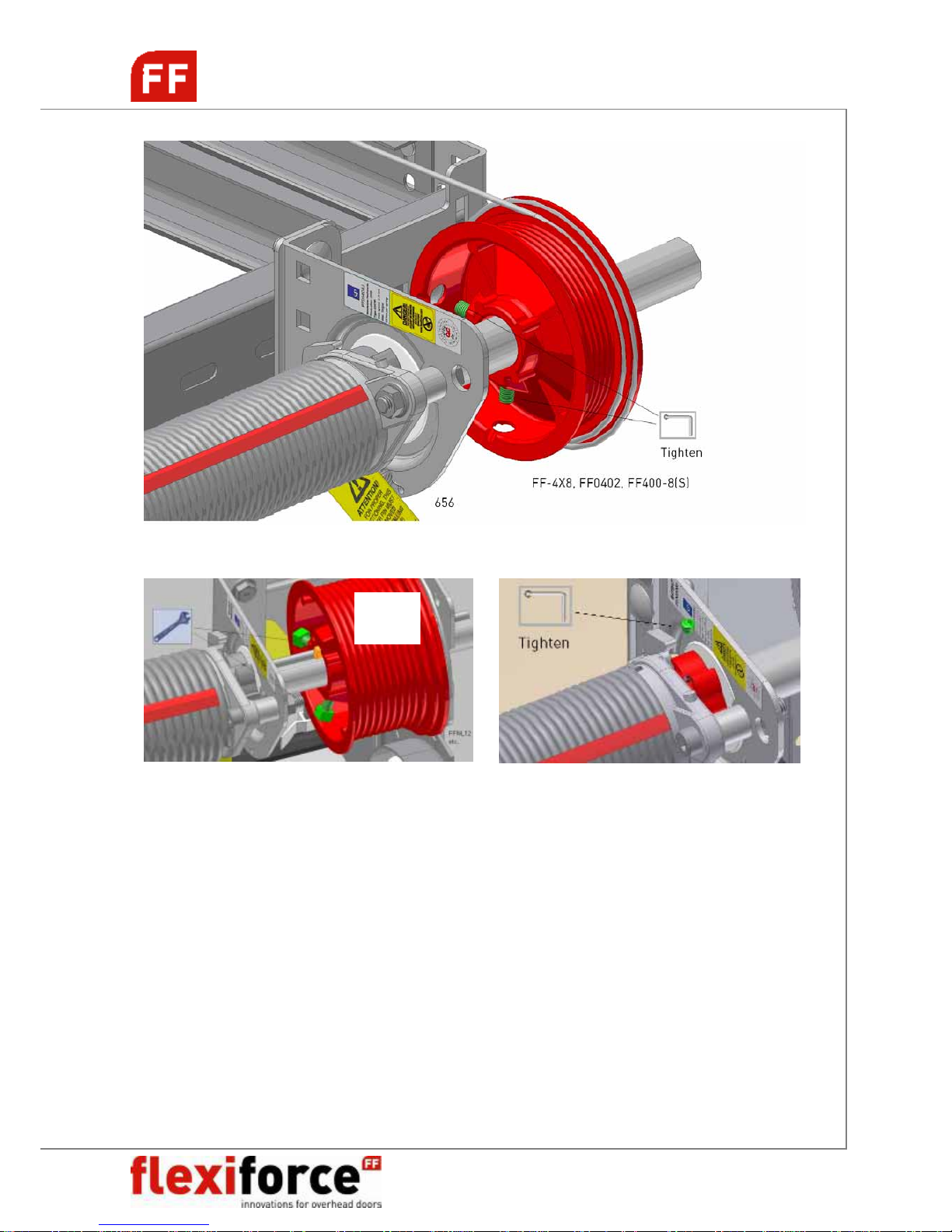
! Cable running behind the rollers to the cable drums
Without key-way: Fix shaft with clamp. Bring cable trough pulley system to rear.
Hook in the cable end in the drum. Rotate the drum for winding the cable.
Position the drum on the shaft.
Page 17
RS70 manual GB 2009 www.flexiforce.com
17
manual
GB
rev.0 Feb-09
With key-way:
NB! See separate manual spring break device installation: 656Manual GB.pdf
Max 10Nm
Max
23 Nm
Page 18
RS70 manual GB 2009 www.flexiforce.com
18
manual
GB
rev.0 Feb-09
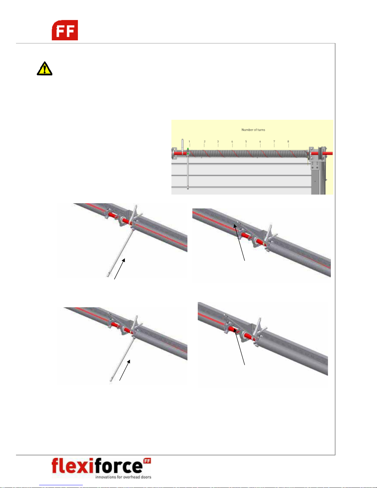
TORSION SPRING TENSIONING
CAUTION!
Torsion springs are subject to considerable tension! Proceed at all times with extreme caution.
Installation, maintenance and repair should be carried out only by experienced and properly trained
overhead door fitters. Use correctly fitting and properly maintained tension levers (FlexiForce
code RES-TB).
Number of turns on the torsion springs:
Height (H) 4 panels 5 panels
2000mm 7.1 turns 6.8 turns
2125mm 7.6 turns 7.3 turns
2250mm 8.0 turns 7.7 turns
2375mm 8.4 turns 8.7 turns
2500mm 8.5 turns 9.2 turns
5 panels 6 panels
2750mm 9,4 turns 9,2 turns
3000mm 10,3 turns 10,0 turns
Insert the 1st tension lever completely into the slot. Turn the 1st tension lever a quarter turn such
that the spring is tensioned.
Insert the 2
nd
lever completely into the next slot. Take over the tension of the spring from the 1st tension
lever to the 2
nd
tension lever. Remove the 1st tension lever from the slot. Turn the 1st tension lever a
quarter turn such the spring is tensioned. Repeat until number of turns is achieved. Then fix the spring
plug to the shaft. Check the door balance and adjust the springs if necessary (equally both springs!)
Page 19
RS70 manual GB 2009 www.flexiforce.com
19
manual
GB
rev.0 Feb-09
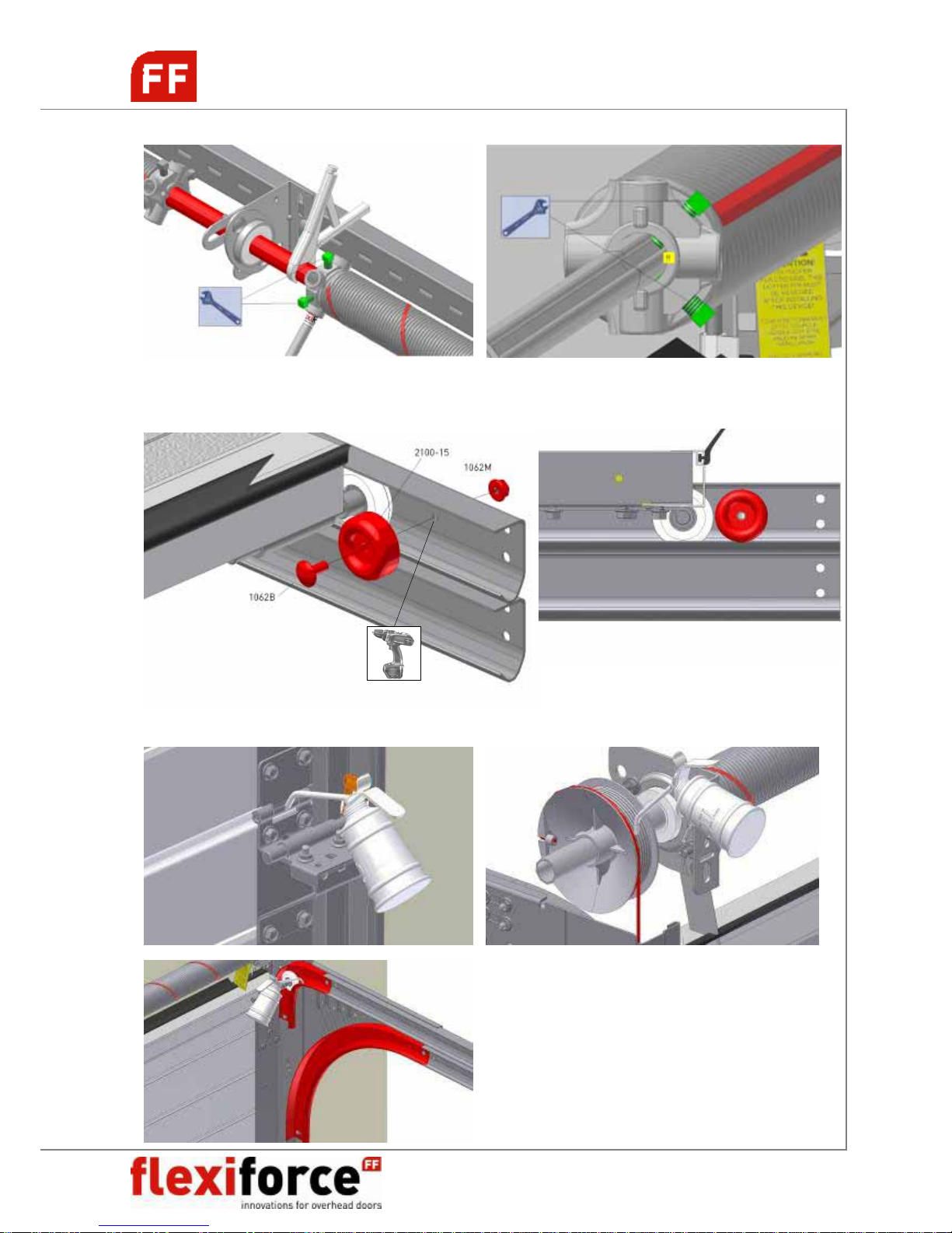
FINISHING THE DOOR
GREASING DOOR PARTS
Max 25 Nm
Page 20
RS70 manual GB 2009 www.flexiforce.com
20
manual
GB
rev.0 Feb-09
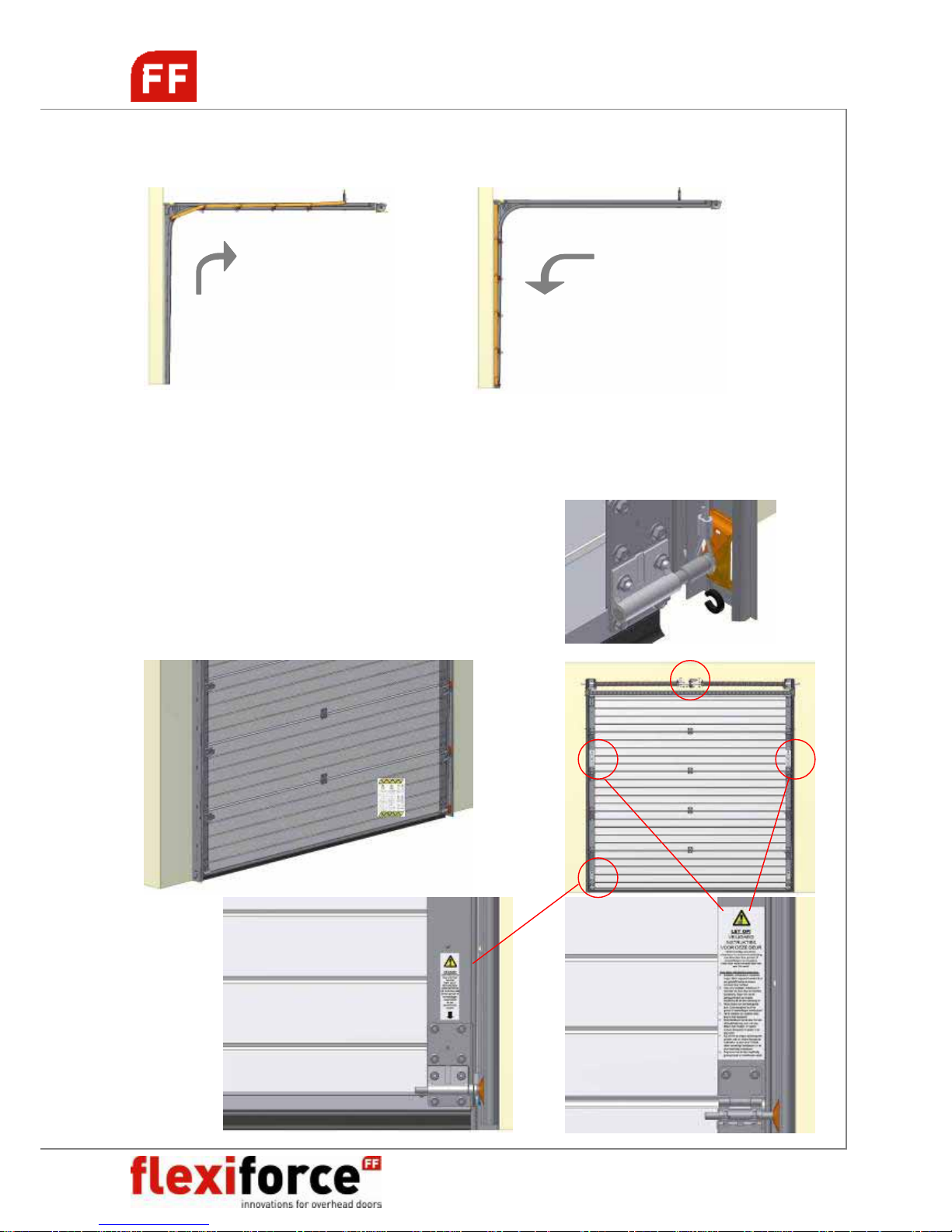
RE-ADJUSTING THE DOOR
Open and close the door for checking all the settings.
When the door panel is not hanging completely horizontally in the lifting cables in (almost) closed
conditions there are several options for fine adjustment.
A. Loosen the securing bolts of the cable drum and the drum relative to the tube shaft.
B. When a coupling is employed this may be adjusted to ensure a better horizontal setting.
Horizontal movement of the door can be limited
(to max. 5mm) by installing 2065 distance rings on the
roller shafts.
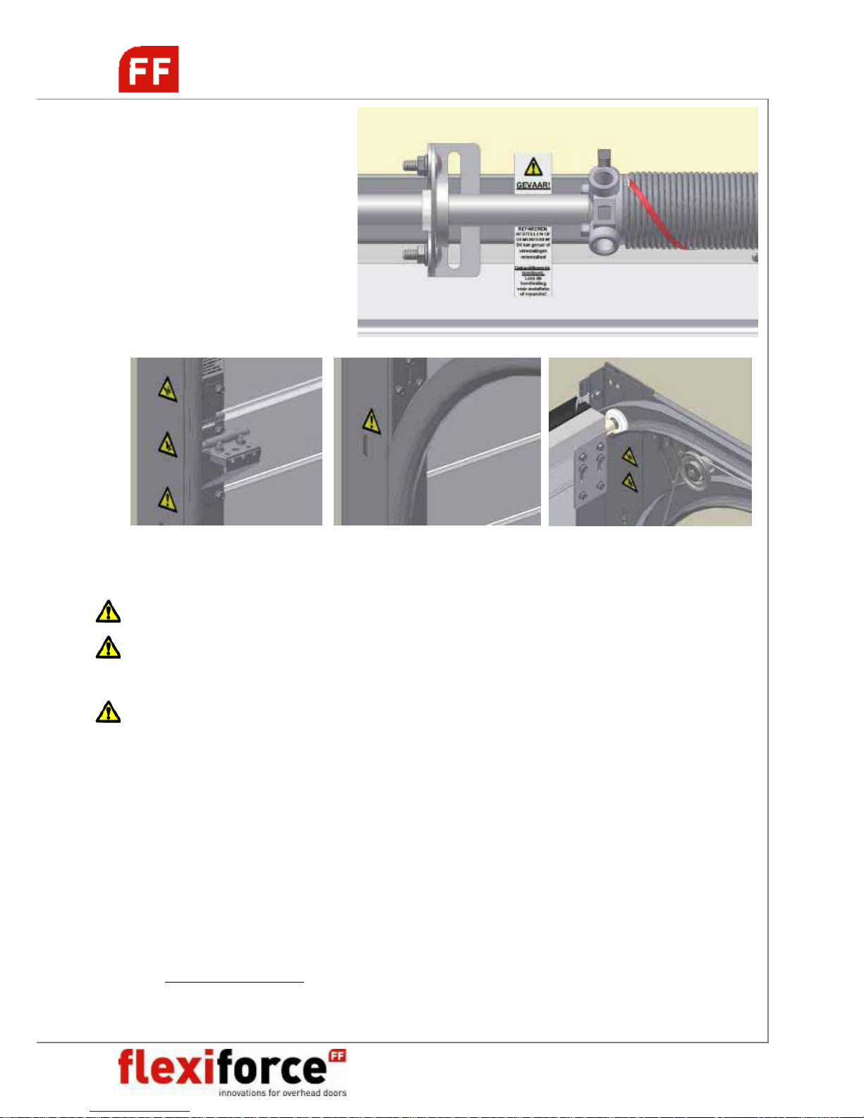
SAFETY LABELS ON THE DOOR
LABEL-GB etc.
A
Page 21
RS70 manual GB 2009 www.flexiforce.com
21
manual
GB
rev.0 Feb-09
Install any additional accessories that you have ordered separately such as:
Handgrip, lock, etc. See separate instructions in product packaging.
NB! A lock may not be fitted to an electrically driven door.
NB! A manually operated door should always be equipped with a hand grip,
installed at a safe location on the door.
NB! Do NOT INSTALL a pull rope with a power operated door at any time!! This
can cause serious injuries or danger to the user of the door!
Place your CE identification plate on the door (mandated!!) together with any
warning labels required.
Hand over necessary documents to the end-user:
o User manual
o Dismantling instructions (included in this manual)
o Maintenance instructions (included in the user manual)
o Service log book
o Declaration of conformity IIa declaring the door is according to
EN-13241-1.
Visit www.flexiforce.com for the most recent update of information on your
obligations towards handing over a safe-to-use door.
A
Page 22
RS70 manual GB 2009 www.flexiforce.com
22
manual
GB
rev.0 Feb-09
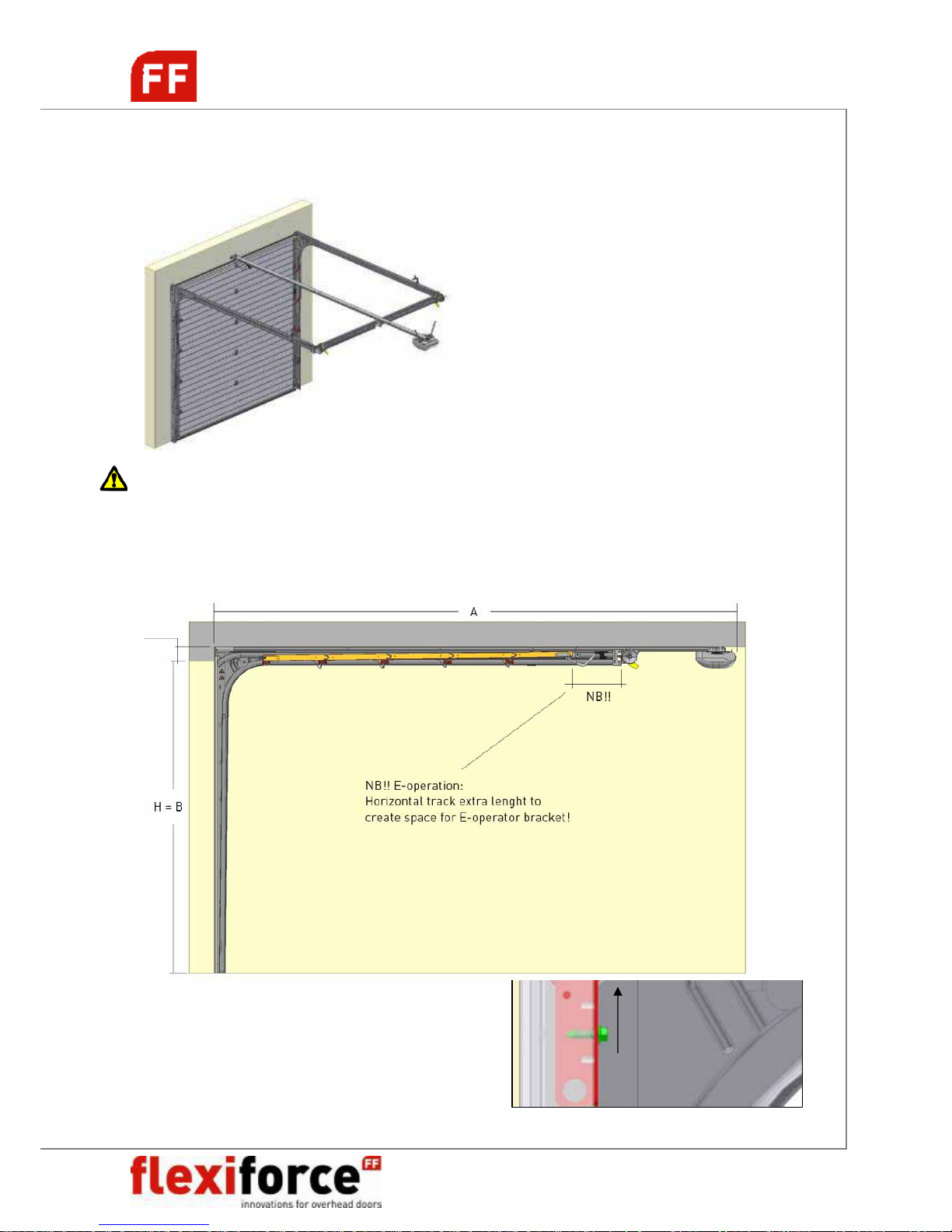
OPTIONAL: E-OPERATION
When you have selected an electrical
operator drive (LIFTMASTER LM60K/R or
other), then this should be assembled in
conformity with the handbook supplied
with this operator and above displayed
instructions. You should clearly follow the
instructions for electrical operation in this
handbook.
In order to maintain the closing peak force
of the door within the CE-standards the
attachment point of the drawbar should be
fixed at the proper position. Ask your
supplier for the correct position!
NB! The person installing the door must check thoroughly if the combination between this
door and the selected operator is safe to use (ITTR-approval report). Keep in mind the
max. peak force that is allowed when closing the door. People could get hurt if the
adjustment of the operator software, or the installation of the operator or the selected
operator on this door, are not checked correctly!!
So combinations: RSV10 + RS70H30
RSV20 + RS70H40
RSV30 + RS70H50
RSV40 + RS70H60
RSV50 + RS70H60
RSV60 + RS70H70
Page 23
RS70 manual GB 2009 www.flexiforce.com
23
manual
GB
rev.0 Feb-09
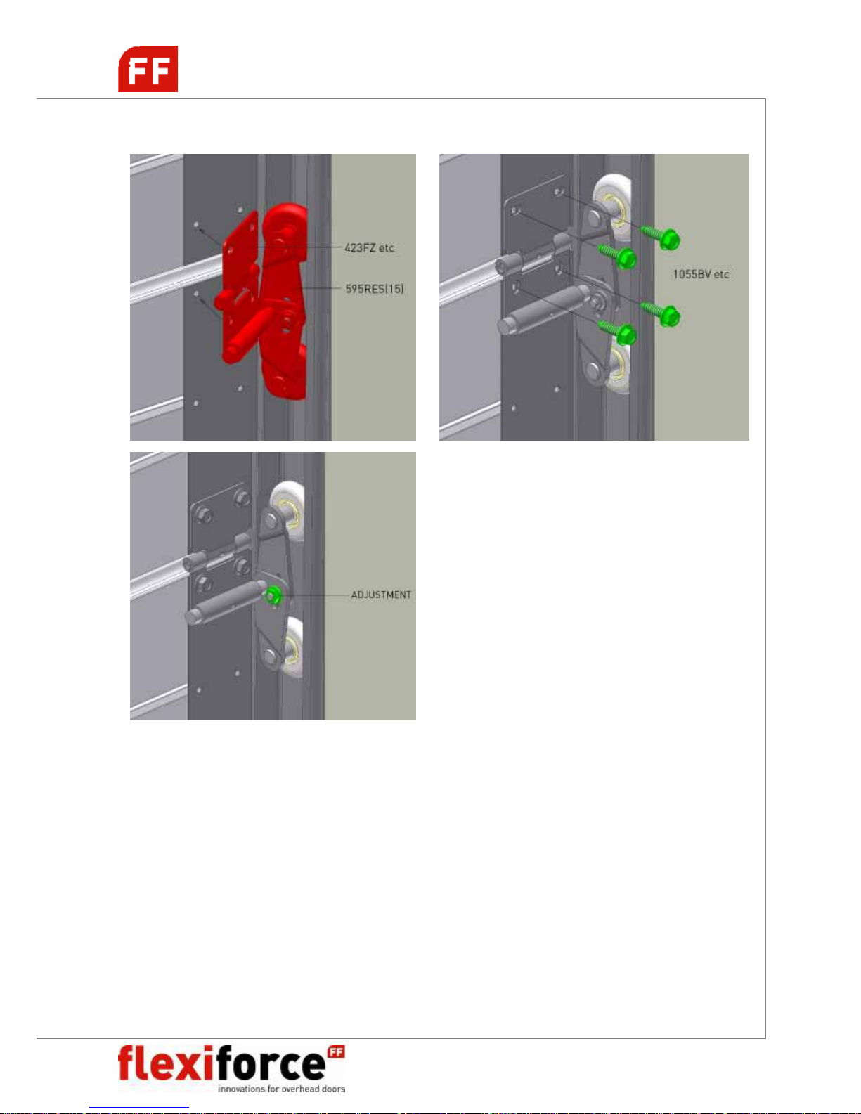
OPTIONAL: TANDEM ROLLERS
Page 24
RS70 manual GB 2009 www.flexiforce.com
24
manual
GB
rev.0 Feb-09
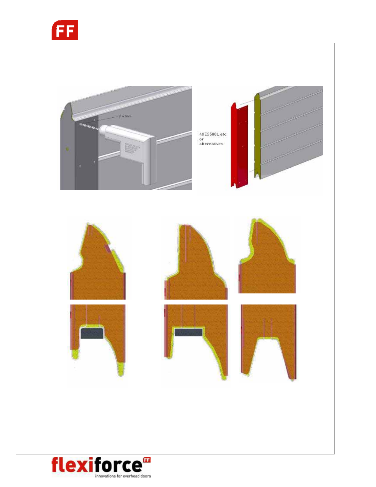
PANEL ASSEMBLY
INSTALLING END CAPS
POSITIONING OF END CAPS PER PANEL BRAND
Kingspan panel Tecsedo panel Metecno panel
40ES500L/R, 40ES610L/R 40TS500L/R, 40TS610L/R 40FS500L/R, 40FS610L/R
40ES500WL/R, 40ES610WL/R (RAL9010) 40TS500WL/R, 40TS610WL/R 40FS500WL/R, 40FS610WL/R
40EM500L/R, 40EM610L/R 40TM500L/R, 40TM610L/R 40FM500L/R, 40FM610L/R
40EM500WL/R, 40EM610WL/R (RAL9010) 40TM500WL/R, 40TM610WL/R 40FM500WL/R, 40FM610WL/R
Page 25
RS70 manual GB 2009 www.flexiforce.com
25
manual
GB
rev.0 Feb-09
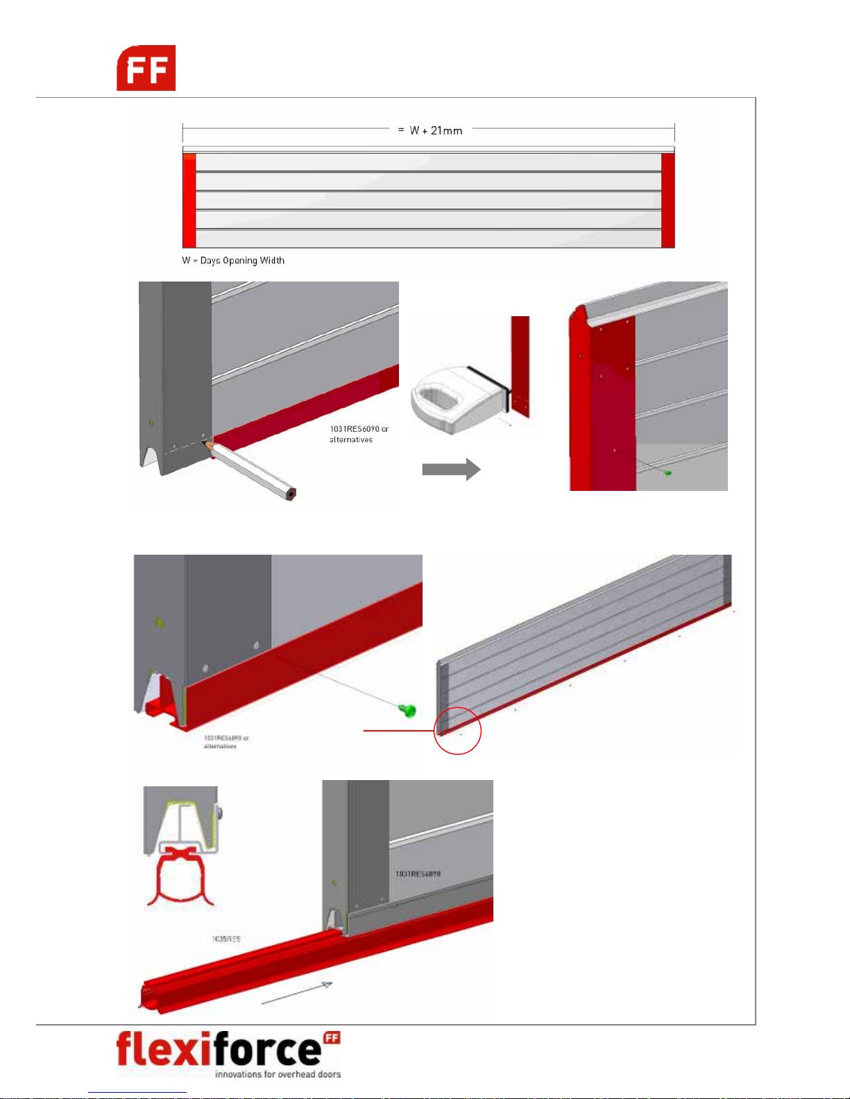
INSTALLING BOTTOM ALU + SEAL
Page 26
RS70 manual GB 2009 www.flexiforce.com
26
manual
GB
rev.0 Feb-09
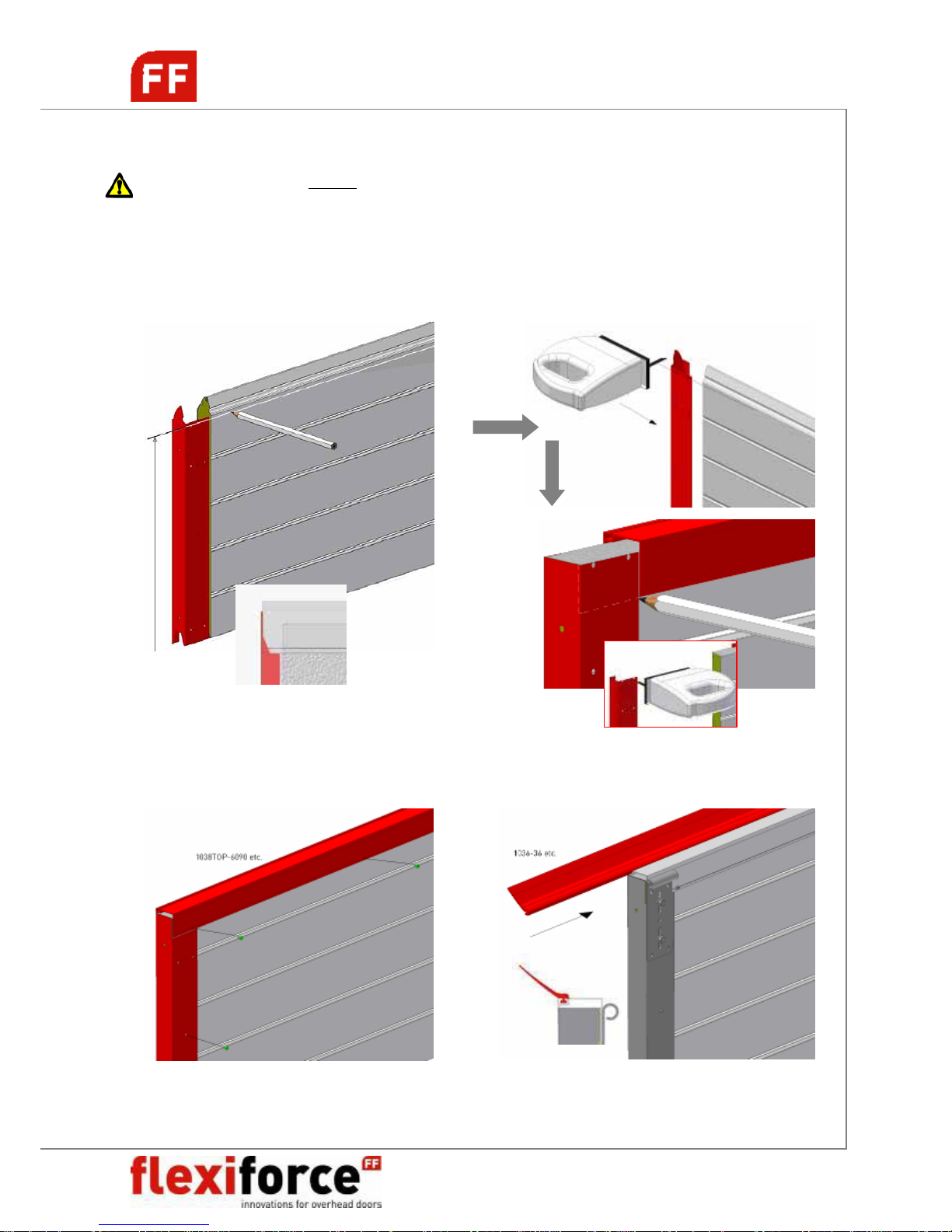
CUTTING / FINISHING TOP PANEL
NB! Make sure that the bottom panel will not be cut for adjusting the panel or door height.
This should be done with the top section only! The attachment of the bottom bracket,
which is holding the complete door weight, is relying on the construction of the panel.
Danger can occur if the panel is cut at this point.
Total door panel height = Days Opening Height (H) + 15mm
Page 27
RS70 manual GB 2009 www.flexiforce.com
27
manual
GB
rev.0 Feb-09
TROUBLESHOOTING
What should be checked if the door is not balanced properly?
When a door is not well in balance, then it is necessary to check first the following details :
1. Is the given information correct :
- weight of the door leaf (including hardware)
- is the division of the weight equal on each panel, or are there panels with a different
weight than the others, for instance by the application of different panels (glass, pass
door with heavy profiles).
2. Are the correct parts supplied and fitted?
especially the drums and springs are important :
- are the correct dimensions supplied ?
3. Is the door properly installed?
- horizontal tracks really horizontally and not with inclination.
4. Were modifications made afterwards ?
- check if any changes were made during the fitting, or if a pass door was fitted later, or
any reinforcement profiles fitted etc.
5. Is the e-operator installed and selected properly?
- Is the installed e-operator suitable for this door?
- Is the e-operator power adjusted properly for this door? (See installation
manual operator)
- Is the connection of the drawbar to the top-panel on the right position? (See
attachment and manual operator).
WHAT TO DO AFTER CABLE BREAK OR SPRING BREAK?
NB! Also make sure to instruct the user about this.
After spring breaking
the door will be stopped by the 656-series spring break devices. The end
user must contact immediately a qualified overhead door mechanic. The spring breaking device
is a so called “one-shot” device. After it has acted, it must be replaced, together will all other
possibly damaged components of the door, such as torsion springs, spring plugs, bearing plates
etc. The door has to be inspected thouroughly. See separate manual 656 spring break device.
After cable breaking
, the door will be stopped by the second cable, which is designed to be
strong enough to hold the weight of the door. Again, qualified overhead door mechanics must
inspect the door and replace all possibly damaged components, such as: bottom brackets,
cable, roller carriers, rollers, etc.
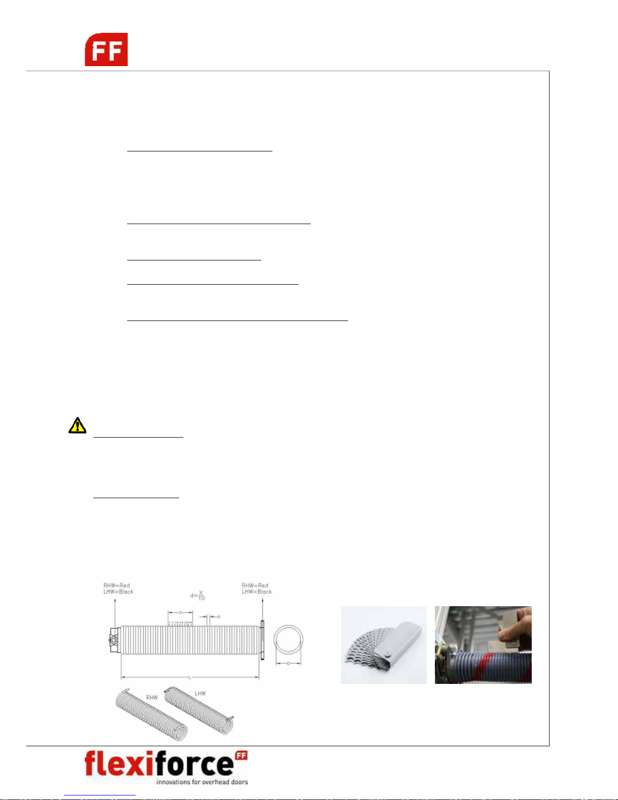
SPRING IDENTIFICATION
FlexiForce® spring gauge: WGD10
Page 28
RS70 manual GB 2009 www.flexiforce.com
28
manual
GB
rev.0 Feb-09
DISMANTLING THE OVERHEAD DOOR
ATTENTION! WARNING!
To dismantle an existing overhead door, a number of precautions must be taken. For the safety
of all concerned pay heed to the warnings and instructions given below! If in doubt, contact your
supplier.
Dismantling should only be carried out by experienced fitters. This manual is not suitable for
d.i.y. purposes or for use by trainee fitters.
This manual only describes the installation/dismantling of hardware for overhead doors and as
such must be supplemented with instructions for any additional components.
FOR ANY DETAILS ON THESE DISMANTLING
INSTRUCTIONS, WE REFER TO THE INSTALLATION
CHAPTERS OF THIS MANUAL WHERE DRAWINGS AND DETAILS ARE DISPLAYED.
STEP 1. De-tensioning the torsion spring(s)
CAUTION ! Torsion springs and bottom brackets are under high tension. Exercise at all times great
caution. Use properly fitting and maintained tension irons (see drawing).
Start dismantling of the door by closing the door and securing its movement with a clamp on the
vertical track. First the tension on the torsions springs and cable has to be released. Do this by
following these instructions :
1 Insert the 1
st
tensioning iron fully into the tensioning aperture.
2 Take over the tension of the spring with this tensioning iron.
3 Loosen the bolts in the tensioning plug and remove the key.
4 Turn the 1
st
tensioning iron in the direction required.
5 Insert the 2
nd
tensioning iron fully into the next tensioning aperture.
6 Take over the tensioning of the spring from the 1
st
tensioning iron with the 2nd tensioning iron.
7 Remove the 1
st
tensioning iron from the aperture.
8 Turn the 2
nd
tensioning iron a quarter turn in the direction required.
9 Insert the 1
st
tensioning iron fully into the tensioning aperture.
10 Take over the tensioning of the spring from the 2nd tensioning iron with the1
st
tensioning iron.
11 Repeat steps 4 through 10 until all tension is released.
12 Remove the last tensioning iron.
STEP 2. Disconnect the electrical operator. Follow any instructions given in the separate manual of
the operator.
STEP 3. Loosen the cable drums and remove the keys. Act carefully, there might be some tension left
on the cable. Check if the cable is slack. Remove the cable by disconnecting it from the bottom bracket
and cable drum.
STEP 4. Dismantle the horizontal track construction.
STEP 5. Remove the panels one by one from the vertical track construction, starting with the top
panel. Do this by loosening the hinges and rollers first.
STEP 6. Remove the shaft construction from the lintel, after you have dismantled the E-operator from
the shaft. If the shaft is divided and connected with a coupler, first disconnect the coupler and
carefully remove both halves of the shaft system.
Attention ! Watch out for parts that might slide of the shaft, such as cable drums, bearings or
keys.
STEP 7. Remove vertical tracks and angles from the building construction.
STEP 8. Make sure that you remove all the parts and panels in an environment kindly way. Check with
your local authorities where and how you can leave this as garbage.
Page 29

RS70 manual GB 2009 www.flexiforce.com
29
manual
GB
rev.0 Feb-09
MAINTENANCE AND REPLACEMENT OF PARTS
RESIDENTIAL DOORS
An overhead door should be maintained and checked regularly to ensure safe operation and
use. This is described in the EN-norms.
GENERAL:
1 Torsion springs, brackets and other components which are attached to the springs
and cables, are under extreem tension. If not handled properly, injuries or damages
might occur!
So, working on these components may only be carried out by qualified
overhead door mechanics!
2 Replacement of broken or weared components should always be done by qualified
overhead door mechanics.
3 When checking the door, always disconnect the electrical main power supply. Make
sure that it is blocked against re-engaging without you knowing it.
REGULAR MAINTENANCE:
After installation:
1. Grease running part of the tracks MECHANIC
2. Grease the bearings of the rollers MECHANIC
3. Grease the shafts of the rollers MECHANIC
4. Grease the bearings of the shaft MECHANIC
5. Grease the hinge pins MECHANIC
6. Grease the lock MECHANIC
7. Protect the panels with carwax USER
8. Grease the rubbers slightly with vasaline USER
After 3 months:
1. Complete inspection visualy MECHANIC
2. Check balancing system and adjust if needed MECHANIC
3. Grease all the above mentioned points if needed MECHANIC
Every 6 months (or after every 750 cycles):
1. Check side seals on damage or wear and tear USER
2. Check top seal on damage or wear and tear USER
3. Check bottom seal on damage or wear and tear USER
4. Grease all above mentioned points USER
5. Clean the panels USER
6. Clean the windows (only water wash, do not use cloth) USER
7. Remove dirt and waste from the door or its surroundings USER
Every 12 months (or after every 1500 cycles):
1. Check or test the fixation of the springs to the fittings MECHANIC
2. Check the balance of the door and adjust if needed MECHANIC
3. Check the cables for damage or wear and tear MECHANIC
4. Check the cable connection points on drums and bottom bracket MECHANIC
5. Check the roller on wear and free moving space MECHANIC
6. Check the hinges on breaking MECHANIC
Page 30

RS70 manual GB 2009 www.flexiforce.com
30
manual
GB
rev.0 Feb-09
7. Check the panels on damage, wear and roust MECHANIC
8. Check the spring breaking device acc. to instructions in manual MECHANIC
9. Check and test the safety edge system with operator MECHANIC
10. Check the manual operation of the door MECHANIC
11. Grease the springs MECHANIC
After two years (or after every 3000 cycles):
1. Grease all the above mentioned points MECHANIC
2. Check or test the fixation of the springs to the fittings MECHANIC
2. Check the balance of the door and adjust if needed MECHANIC
3. Check the cables for damage or wear and tear MECHANIC
4. Check the cable connection points on drums and bottom bracket MECHANIC
5. Check the roller on wear and free moving space MECHANIC
6. Check the hinges on breaking MECHANIC
7. Check the panels on damage, wear and roust MECHANIC
8. Check the spring breaking device acc. to instructions in manual MECHANIC
9. Check and test the safety edge system with operator MECHANIC
10. Check the manual operation of the door MECHANIC
11. Grease the springs MECHANIC
12. Check side seals on damage or wear and tear MECHANIC
13. Check top seal on damage or wear and tear MECHANIC
14. Check bottom seal on damage or wear and tear MECHANIC
` 15. Check the shaft on wear and tear or damage MECHANIC
16. Check the bottom bracket on wear and tear and damage MECHANIC
17. Check the connection of the drum to the shaft (keys!) MECHANIC
18. Check and re-fix the bolt of the coupler MECHANIC
19. Check the connections of the track system MECHANIC
20. Check the suspension of the door to the lintel and ceiling MECHANIC
Use for greasing : PTFE or SAE20 or WD40
Use for cleaning : Soft soap with water. Do not use aggressive soap or cloth.
 Loading...