

Page 1
PF7 Peristaltic Filler User Manual
m-PF7-Peristaltic Filler User
Manual-02:PB0439/2
1
Contents
1 Declaration of conformity 3
2 Declaration of incorporation 4
3 Safety notes 5
4 Peristaltic pumps - an overview 8
5 When you unpack your pump 9
5.1 Unpacking your pump 9
5.2 Packaging disposal 9
5.3 Inspection 9
5.4 Components supplied 9
5.5 Storage 9
6 Pump operation 10
6.1 Keypad 10
6.2 Glossary of icons 10
6.3 Switching the pump on for the first time 11
6.4 Switching the pump on in subsequent power cycles 15
6.5 Menu navigation 16
6.6 Recipe Mode 16
6.7 Priming and continuous pumping mode 18
6.8 Calibrate mode 19
6.9 Dispense Mode 21
6.10 Reports mode 26
6.11 Settings mode 26
7 Setting up the fluid path 30
7.1 Tube selection 30
7.2 Placing the product container 31
7.3 Y-connector selection 32
7.4 Loading the tube 32
EN EN EN EN EN EN EN EN EN EN EN EN EN EN EN EN EN
Page 2

2
m-PF7-Peristaltic Filler User
Manual-02:PB0439/2
8 Good pump installation practice 34
8.1 General recommendations 34
8.2 Dos and don'ts 34
9 Connecting to a power supply 35
10 Control wiring 36
11 Pump specifications 38
11.1 Specification ratings 38
12 Troubleshooting 39
13 Pump maintenance (including cleaning) 40
13.1 Service 40
13.2 Cleaning 40
13.3 Pumphead Removal 40
14 Warranty 41
15 Information for returning pumps 42
16 Name and address of manufacturer 42
17 Disclaimers 42
Page 3
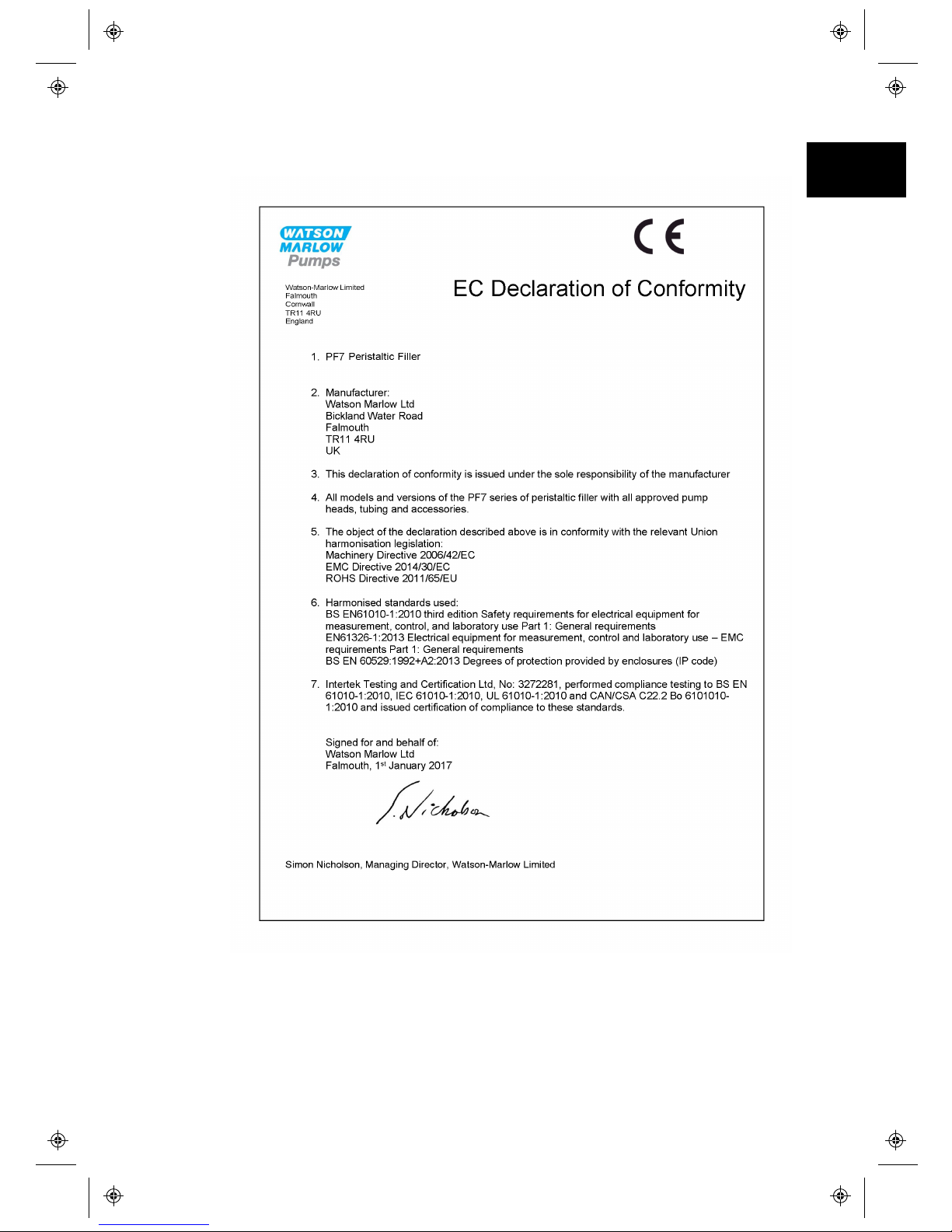
1 Declaration of conformity
m-PF7-Peristaltic Filler User
Manual-02:PB0439/2
3
EN EN EN EN EN EN EN EN EN EN EN EN EN EN EN EN EN
Page 4
4
m-PF7-Peristaltic Filler User
Manual-02:PB0439/2
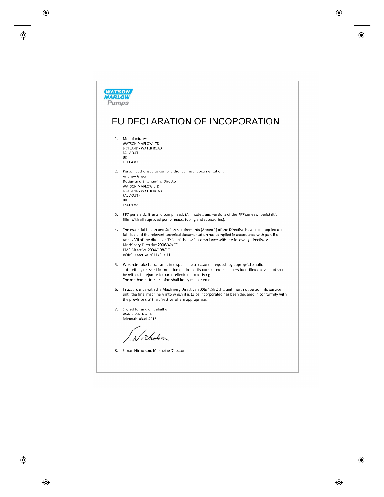
2 Declaration of incorporation
Page 5
3 Safety notes
This safety information should be used in conjunction with the rest of this operating
manual.
In the interests of safety, this pump and pumphead should only be used by
competent, suitably trained personnel after they have read and understood the
manual and considered any hazard involved. If the pump is used in a manner not
specified by Watson- Marlow Ltd, the protection provided by the pump may be
impaired. Any person who is involved in the installation or maintenance of this
equipment should be fully competent to carry out the work. In the UK this person
should also be familiar with the Health and Safety at Work Act 1974.
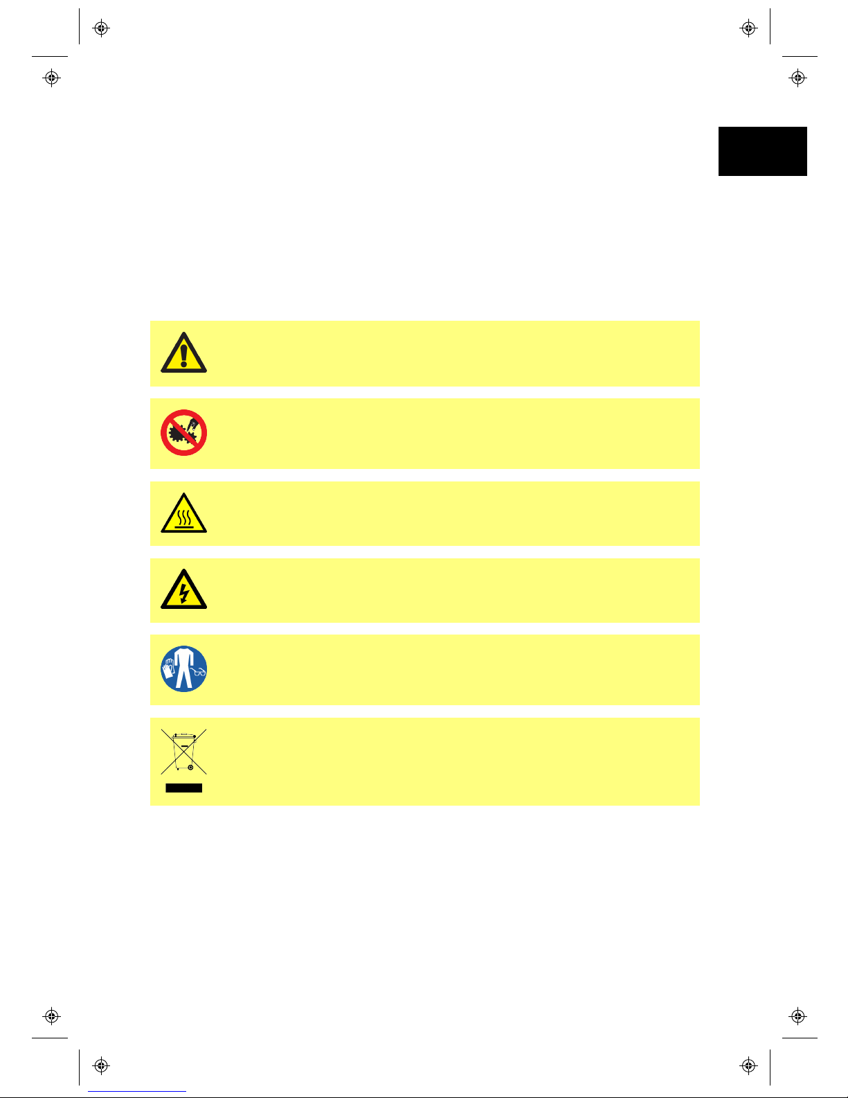
This symbol, used on the pump and in the manual, means: Caution,
refer to accompanying documents.
This symbol, used on the pump and in the manual, means: Do not
allow fingers to contact moving parts.
This symbol, used on the pump and in the manual, means: Caution,
hot surface.
This symbol, used on the pump and in the manual, means: Caution,
risk of electric shock.
This symbol, used on the pump and in the manual, means: Personal
Protective Equipment (PPE) must be worn.
This symbol, used on the pump and in the manual, means: Recycle
this product under the terms of the EU Waste Electrical and Electronic
Equipment (WEEE) Directive.
m-PF7-Peristaltic Filler User
Manual-02:PB0439/2
5
EN EN EN EN EN EN EN EN EN EN EN EN EN EN EN EN EN
Page 6
6
m-PF7-Peristaltic Filler User
Manual-02:PB0439/2
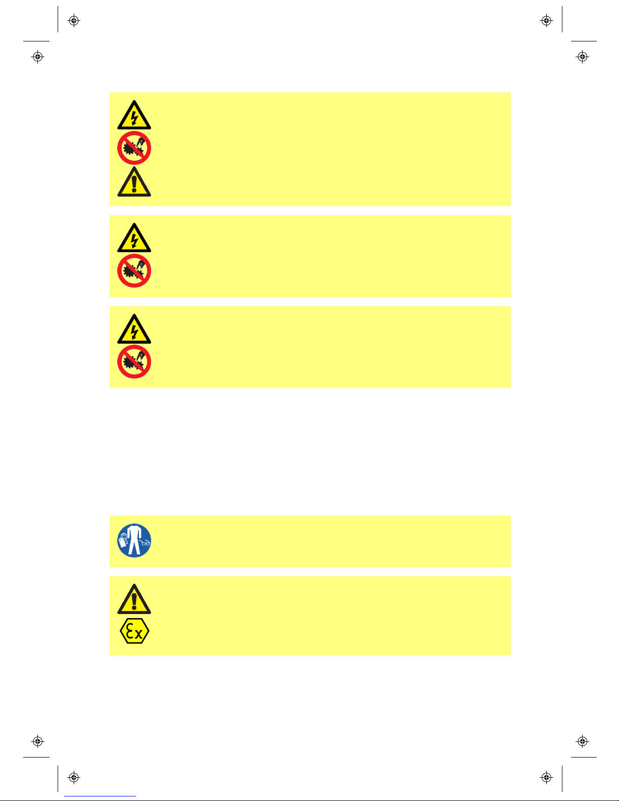
Fundamental work with regard to lifting, transportation, installation,
starting-up, maintenance and repair should be performed by qualified
personnel only. The unit must be isolated from mains power while
work is being carried out. The motor mus t be secured against
accidental start-up.
There is a user-replaceable type fuse in the fuse holder above the
power input connector at the back of the pump . In some countries, the
mains power plug contains an additional replaceable fuse.
There are no user-serviceable fuses or parts inside this pump.
This pump must be used only for its intended purpose.
The pump must be accessible at all times to facilitate operation and maintenance.
Access points must not be obstructed or blocked. Do not fit any devices to the drive
unit other than those tested and approved by Watson-Marlow Ltd. Doing so could
lead to injury to persons or damage to property for which no liability can be
accepted.
The pump's main plug is the disconnecting device (for isolating the motor drive
from the mains supply in an emergency). Do not position the pump so that it is
difficult to disconnect the mains plug.
If hazardous fluids are to be pumped, safety procedures specific to
the particular fluid and application must be put in place to protect
against injury to persons.
This product does not comply with the ATEX directive and must not be
used in explosive atmospheres.
Page 7
The PF7 contains a non- replaceable Manganese Dioxide Lithium Battery (Li/MnO2),
IEC CR2032, with a typical capacity of 225mAh, containing 0.07g of Lithium.
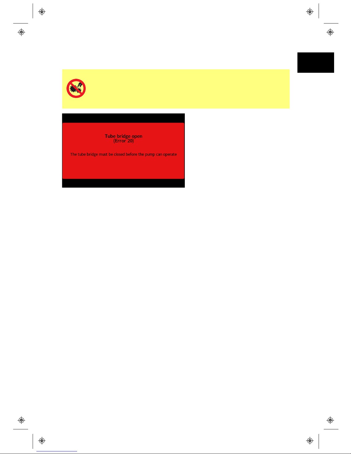
Primary operator protection from rotating parts of this pump is
provided by isolating the pump from mains power before opening the
pump head tube bridge. The pump also provides a tube bridge open
indicator. If the tube bridge is opened, the tube bridge open screen is
displayed.
The tube bridge must be closed for the warning screen to clear and the pump to
start.
m-PF7-Peristaltic Filler User
Manual-02:PB0439/2
7
EN EN EN EN EN EN EN EN EN EN EN EN EN EN EN EN EN
Page 8

8
m-PF7-Peristaltic Filler User
Manual-02:PB0439/2
4 Peristaltic pumps - an overview
Peristaltic pumps are the simplest possible pump, with no valves, seals or glands to
clog or corrode. The fluid contacts only the bore of a tube, eliminating the risk of the
pump contaminating the fluid, or the fluid contaminating the pump.
How they work
A compressible tube is squeezed between a roller and a track on an arc of a circle,
creating a seal at the point of contact. As the roller advances along the tube, the
seal also advances. After the roller has passed, the tube returns to its original
shape, creating a partial vacuum which is filled by fluid drawn from the inlet port.
Before the roller reaches the end of the track, a second roller compresses the tube
at the start of the track, isolating a packet of fluid between the compression points.
As the first roller leaves the track, the second continues to advance, expelling the
packet of fluid through the pump’s discharge port. At the same time, a new partial
vacuum is created behind the second roller into which more fluid is drawn from the
inlet port.
Backflow and siphoning do not occur, and the pump effectively seals the tube when
it is inactive. No valves are needed.
The principle may be demonstrated by squeezing a soft tube between thumb and
finger and sliding it along: fluid is expelled from one end of the tube while more is
drawn in at the other.
Animal digestive tracts function in a similar way.
Suitable applications
Peristaltic pumping is ideal for most fluids, including viscous, shear- sensitive,
corrosive and abrasive fluids, and those containing suspended solids. They are
especially useful for pumping operations where hygiene is important.
Peristaltic pumps operate on the positive displacement principle. They are
particularly suitable for metering, dosing and dispensing applications. Pumps are
easy to install, simple to operate and inexpensive to maintain.
Page 9

5 When you unpack your pump
5.1 Unpacking your pump
Unpack all parts carefully, retaining the packaging until you are sure all
components are present and in good order. Check against the components supplied
list, below.
5.2 Packaging disposal
Dispose of packaging materials safely, and in accordance with regulations in your
area. The outer carton is made of corrugated cardboard and can be recycled.
5.3 Inspection
Check that all components are present. Inspect components for damage in transit.
If anything is missing or damaged, contact your distributor immediately.
5.4 Components supplied
• PF7 pump drive unit, fitted with QC12 pumphead
• A QC12 pumphead tube clamp set
• The designated power cable
• Product manual
5.5 Storage
This product has an extended shelf life. However, care should be taken after
storage to ensure that all parts function correctly. Please observe the storage
recommendations and use- by dates which apply to tubing you may wish to bring
into service after storage.
m-PF7-Peristaltic Filler User
Manual-02:PB0439/2
9
EN EN EN EN EN EN EN EN EN EN EN EN EN EN EN EN EN
Page 10
10
m-PF7-Peristaltic Filler User
Manual-02:PB0439/2
6 Pump operation
6.1 Keypad
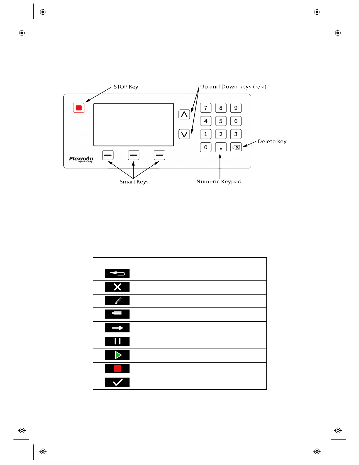
The STOP key will immediately stop the pump, regardless of what screen is
currently displayed. If the pump is stopped part way through a fill, a message
stating this will be displayed.
6.2 Glossary of icons
The PF7 uses a range of graphical icons to help navigation, in both the smart key
function indicator area and the screen info bar area.
Smart key icons
BACK TO PREVIOUS SCREEN
NO / CANCEL
EDIT
MODE
NEXT
PAUSE
RUN
STOP
YES/CONTINUE
Page 11
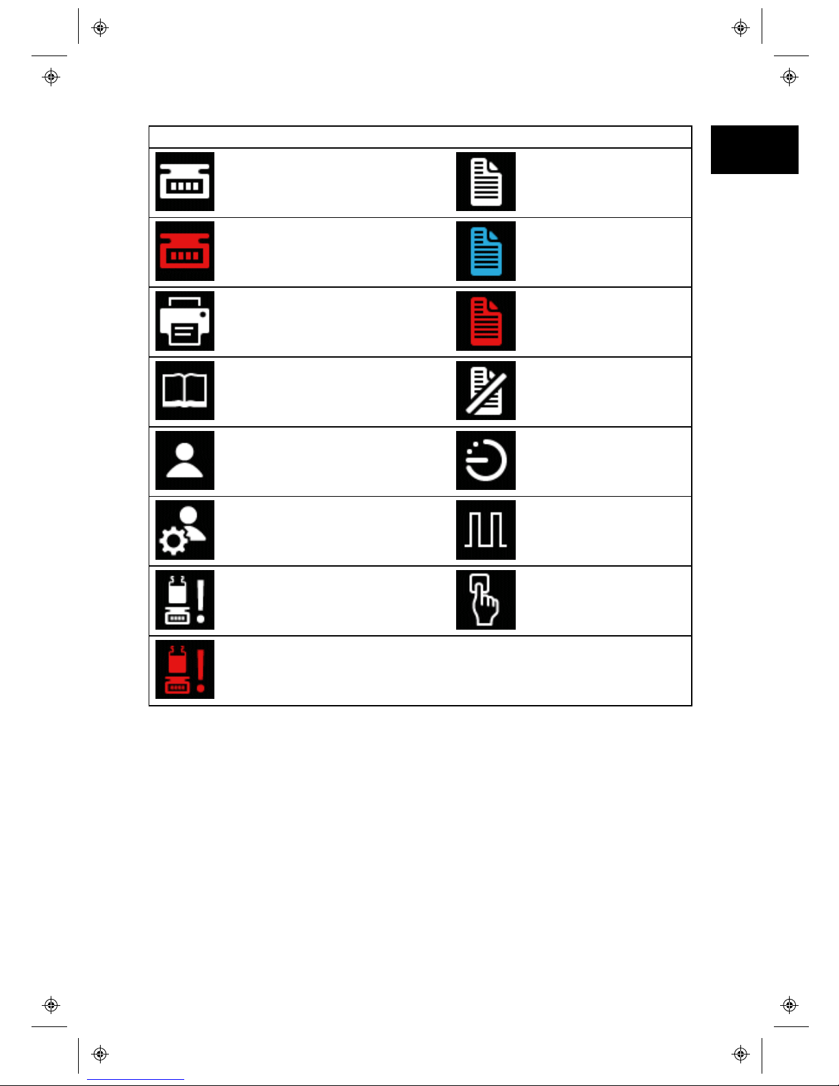
Screen info icons
BALANCE CONNECTED (White Icon)
REPORTING ON (White
Icon)
BALANCE CONNECTED
BUT NOT USABLE (Red Icon)
REPORTING IN PROGRESS
(Blue Icon)
PRINTER CONNECTED
REPORTING ERROR
(Red Icon)
RECIPE REPORTING OFF
USER
FILL ACTIVATION BY TIME
DELAY
ADMINISTRATOR
FILL ACTIVATION BY
EXTERNAL INPUT
RECALIBRATION REMINDER
FILL ACTIVATION BY
KEYPAD
RECALIBRATION REQUIRED
(Red Icon)
6.3 Switching the pump on for the first time
Powering up
Power up the pump. The pump displays the start-up screen with the Flexicon logo.
m-PF7-Peristaltic Filler User
Manual-02:PB0439/2
11
EN EN EN EN EN EN EN EN EN EN EN EN EN EN EN EN EN
Page 12
12
m-PF7-Peristaltic Filler User
Manual-02:PB0439/2
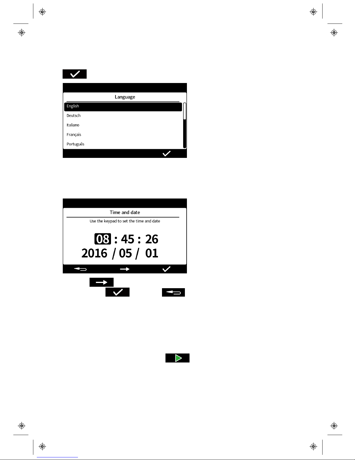
Language selection
Select the display language using the up and down keys ( ∧ / ∨) and then the
.
Setting the time and date
Enter the time and date using the numeric keypad. The time format is hh/mm/ss
and the date format is yyyy/mm/dd. The time is 24hr format.
Pressing will move the selection forward. Once the time and date is
correct, press . Pressing at any point returns to the previous
screen.
Setting the filling method
The filling method defines how each fill will be started.
Time delay between fills, the next fill starts automatically at a set time delay
after the previous fill ends.
Keypad to start each fill, requires to be pressed to start every fill.
External input to start each fill , starts a fill whenever a signal is received
through the start input pin.
Page 13
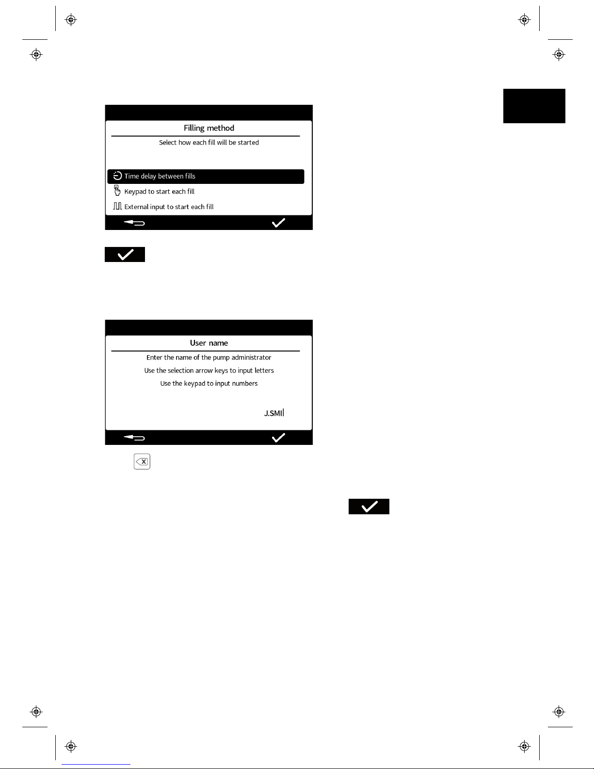
The Filling method icon will be displayed in the screen info bar area.
Select the display language using the up and down keys ( ∧/ ∨) and then press
. The filling method can be reset in settings mode
Setting the pump administrator
Enter a username for the pump administrator. The default username is USER1.
Press to delete characters.
Use the up and down keys (∧/∨) to scroll through the available characters. After 1
second of inactivity the next character can be entered. Use the numeric keypad to
enter numbers. Once the username is correct, press .
Additional users can be set up in settings mode.
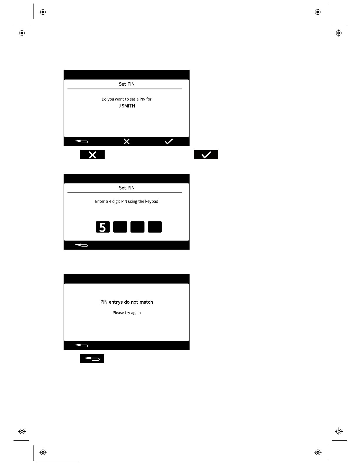
Setting a PIN
By setting a PIN number, a 4 digit number will be required to log in as the pump
administrator. A log in is required whenever the pump is powered on or a user has
logged out.
m-PF7-Peristaltic Filler User
Manual-02:PB0439/2
13
EN EN EN EN EN EN EN EN EN EN EN EN EN EN EN EN EN
Page 14
14
m-PF7-Peristaltic Filler User
Manual-02:PB0439/2
Ensure you keep a record of PIN numbers. If you lose them contact your local
Watson-Marlow Ltd or Flexicon representative.
Press if a pin is not required or press if a PIN is required
If a pin is required, enter a 4 digit number using the numeric keypad
Re-enter the PIN when requested.
If the entry’s don’t match, the following screen will be displayed.
Press to return to the first PIN entry screen.
Page 15
6.4 Switching the pump on in subsequent power cycles
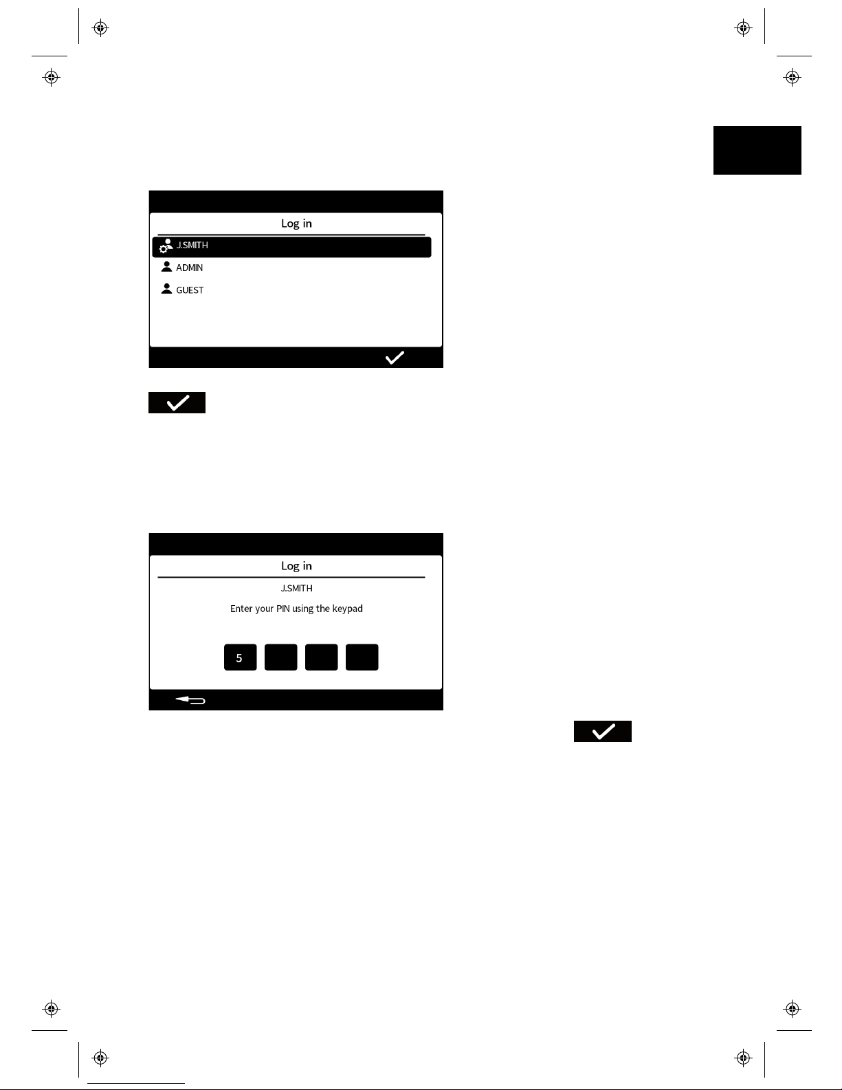
Subsequent power- up sequences will show the initialisation screen and then the
Log-in screen.
Select the desired username using the up and down keys ( ∧/∨) and then press
.
The icon by the username indicates the type of user; either a pump administrator or
a user.
Entering your PIN number
If a PIN has been set for the selected user the following screen will be displayed.
Enter a 4 digit number using the numeric keypad and then press .
If an incorrect PIN is entered "Incorrect PIN, please try again" will be displayed.
m-PF7-Peristaltic Filler User
Manual-02:PB0439/2
15
EN EN EN EN EN EN EN EN EN EN EN EN EN EN EN EN EN
Page 16
16
m-PF7-Peristaltic Filler User
Manual-02:PB0439/2
6.5 Menu navigation
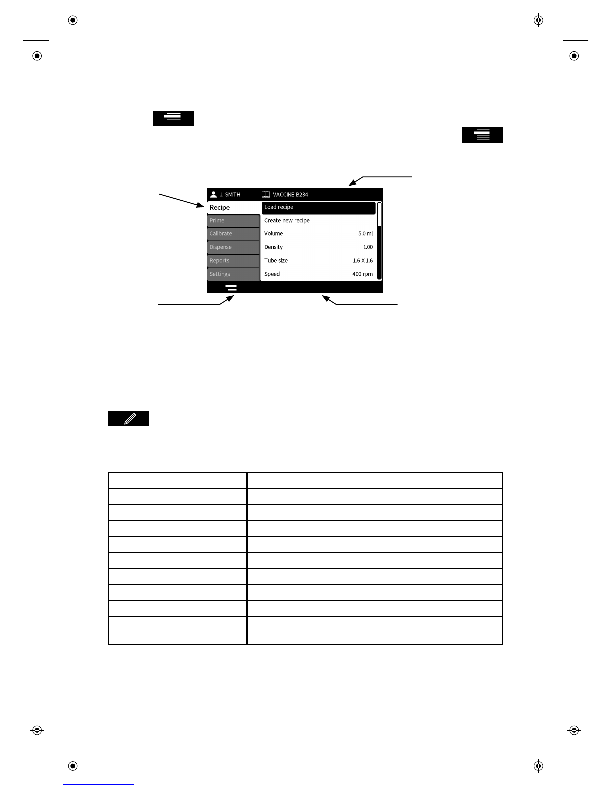
Pressing scrolls through the PF7’s different modes. The active mode is
shown by the highlighted tab. The mode can be changed whenever the
icon is displayed. The PF7 has three smart keys, these change functionality
depending on the screen being displayed.
MODE tabs
MODE Icon Smart key icon bar
Screen info bar
6.6 Recipe Mode
Up to 200 recipes and 50 users can be stored in memory.
Editing a recipe
Select the Recipe tab to enter the recipe details.
Navigate through the recipe items using the up and down arrows (∧/∨) and press
to edit the value.
Each recipe item has clear entry instructions on the screen on how to edit or enter
details.
Recipe Item Description
Load recipe Load a recipe from a li st of stored recipes
Create a new recipe Create a new recipe using the recipe items set
Volume Fill vol ume
Density Fluid density
Tube size Tube size selection
Speed Pumphe ad rotor speed
Acceleration Rate at which the motor accelerates
Deceleration Rate at which the motor decelerates
Anti-drip Relative amount at which the motor reverses at the end
of each dispense
Page 17
Recipe Item Description
Start delay Length of time from the pump rece iving a sta rt signal
and the fill starting, (keypad or external input)
End delay Length of time from the motor stopping and the pump
being ready to start the next fill
First Fill delay The time betwee n a start signal and the first fill starting
Betwe en fill delay The time betwee n one fill endi ng and the next fill
starting
Recalibrati on reminder Peri od between recalibra tions after which a reminder
will be displayed
Recalibrati on pause Period between recalibrations after which the batch will
be paused until a recalibration is performed
Protected recipe If a recipe is set to be protected then it cannot be edited
in any way
Save recipe Saves the current filling paramete rs under a recipe
name
Print recipe Prints the current filling paramete rs
Dele te recipe Dele tes a saved reci pe
Creating a new recipe
When the Create new recipe option is used, some of the recipe parameters are
automatically generated to give the recommended values for that fill. However, all
recipe parameters can be edited after the new recipe has been created.
Remember that filling accuracy can also be influenced by the length of the tubing
and the position of the product tank.
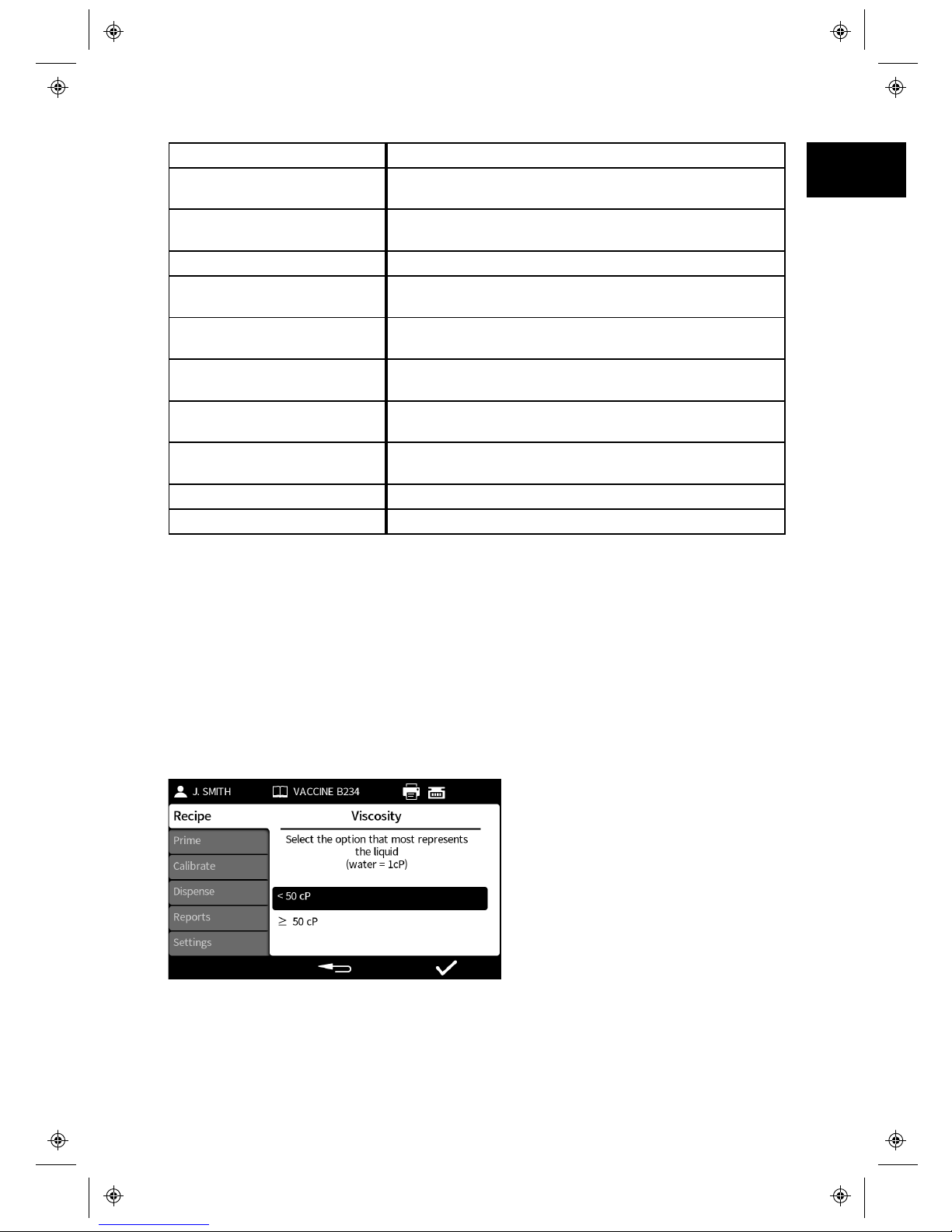
Whilst creating a new recipe, you will be asked if the viscosity of your liquid is most
closely represented by the range (less than) <50cP or by the range (greater than)
>50cP.
m-PF7-Peristaltic Filler User
Manual-02:PB0439/2
17
EN EN EN EN EN EN EN EN EN EN EN EN EN EN EN EN EN
Page 18
18
m-PF7-Peristaltic Filler User
Manual-02:PB0439/2
6.7 Priming and continuous pumping mode
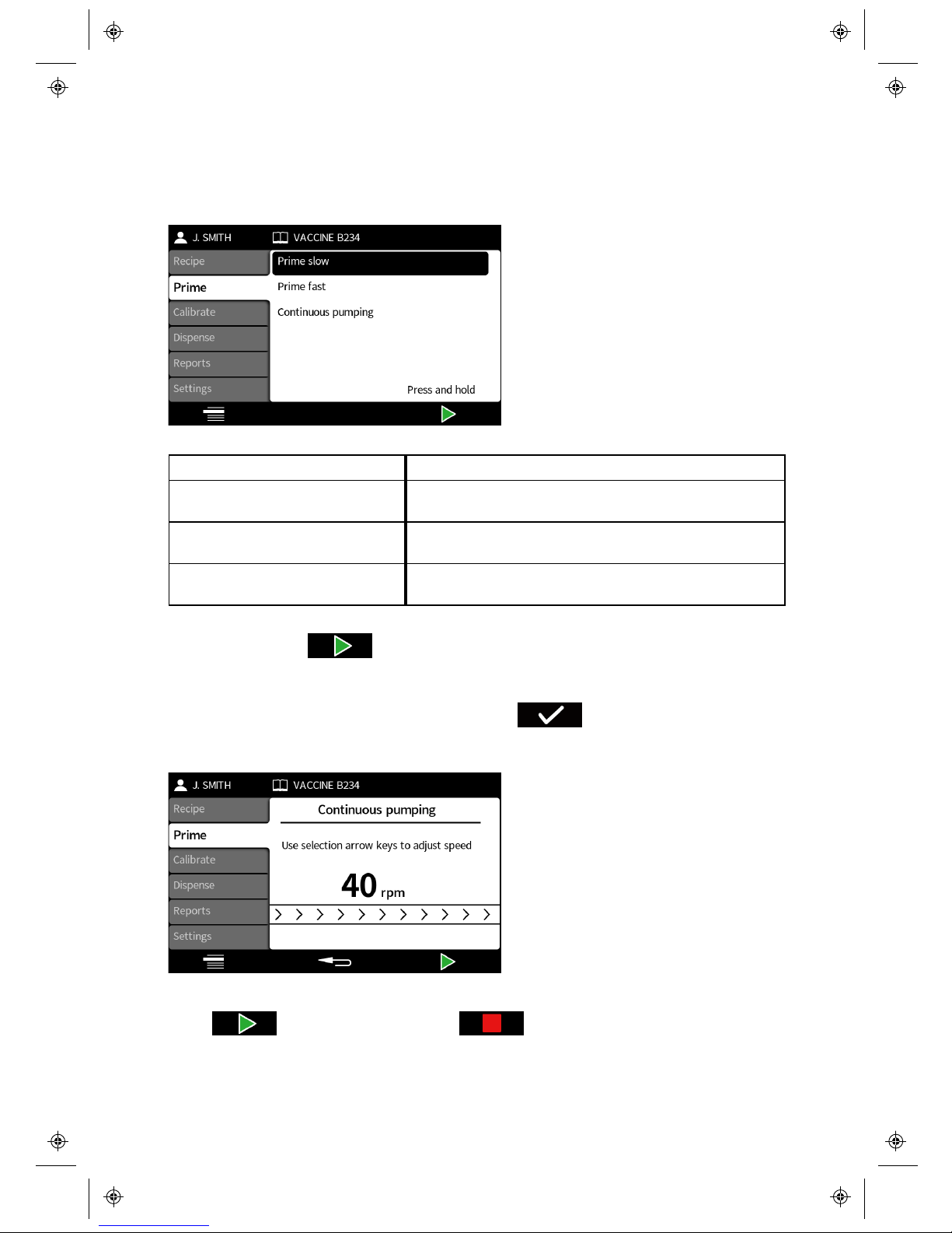
The Prime mode allows you to prime the pump or run the pump continuously.
Navigate through the prime items using the up and down keys (∧/∨).
Prime item Description
Prime slow The pump will run forwards (slowly) as long as the
key is held down
Prime fast The pump will run forwards (fast) as long as the key
is held down
Continuous pumping The pump will run forwards at the set speed until the
stop key is presse d
Press and hold the key to prime the pump when using prime slow or prime
fast. The speed of the prime slow and prime fast can be adjusted in the settings
menu.
If continuous pumping is highlighted and the is selected the continuous
pumping screen is displayed. This allows you to select the speed the pump runs at
when continuously pumping.
Adjust the pump speed using the up and down keys (∧/∨).
Press to Start pumping. Press or the Stop key to stop pumping.
Page 19
6.8 Calibrate mode
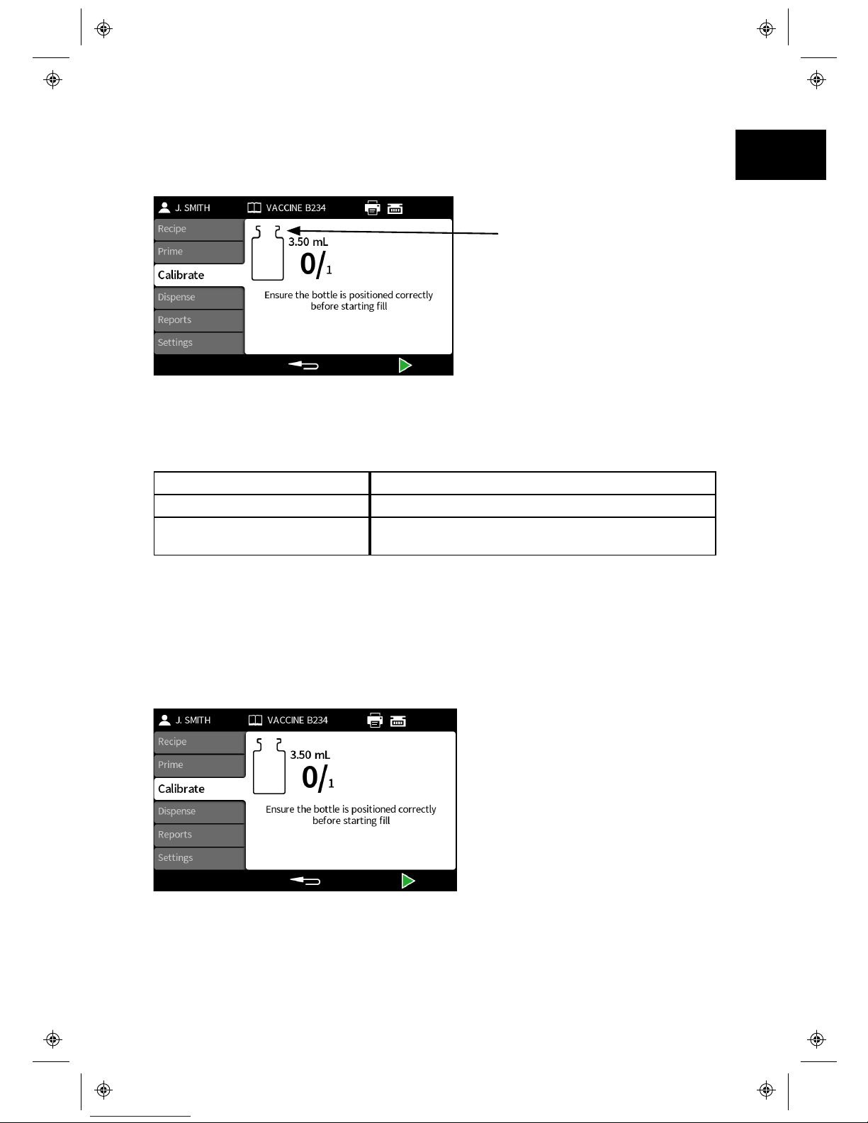
Calibrating the pump before starting a batch and following any change to the recipe
or fluid path is recommended to achieve the optimum filling accuracy.
Calibration icon: The number
within the vial shows how
many calibration fills have
been carried out since the last
batch or recipe parameters
change
The pump uses the current recipe parameters during the calibration process, i.e.
volume, density, tube size, speed, acceleration, deceleration, and anti-drip. The
units used in calibration can be volume or mass and are set through the settings
tab.
Calibrate item Description
Single fill cal ibration A calibration is done using a single fill
Multi-fill calibration A calibration is done using an average value
calculated from all the fill s taken (2 and 99 fills)
If Multi-fill calibration is selected, a screen will be displayed to enter the number of
fills that will be used to create an average fill calibration value.
If a balance is being used, it should be tared (set to zero) using the bottle(s) that
will be used for the calibration fill(s)
Calibration fill(s)
How the fill(s) are started depends on the selected filling method.
m-PF7-Peristaltic Filler User
Manual-02:PB0439/2
19
EN EN EN EN EN EN EN EN EN EN EN EN EN EN EN EN EN
Page 20
20
m-PF7-Peristaltic Filler User
Manual-02:PB0439/2
Time delay between fills - Press or use the external input to start the
first calibration fill. If doing a Multi- fill calibration, any further fills will start
automatically after the Between fill delay has elapsed.
Keypad to start each fill - Press to start the first calibration fill. If doing
a Multi-fill calibration, press to start any further fills.
External input start each fill - Press or use the external input to start
the first calibration fill. If doing a Multi-fill calibration, press or use the
external input to start any further fills.
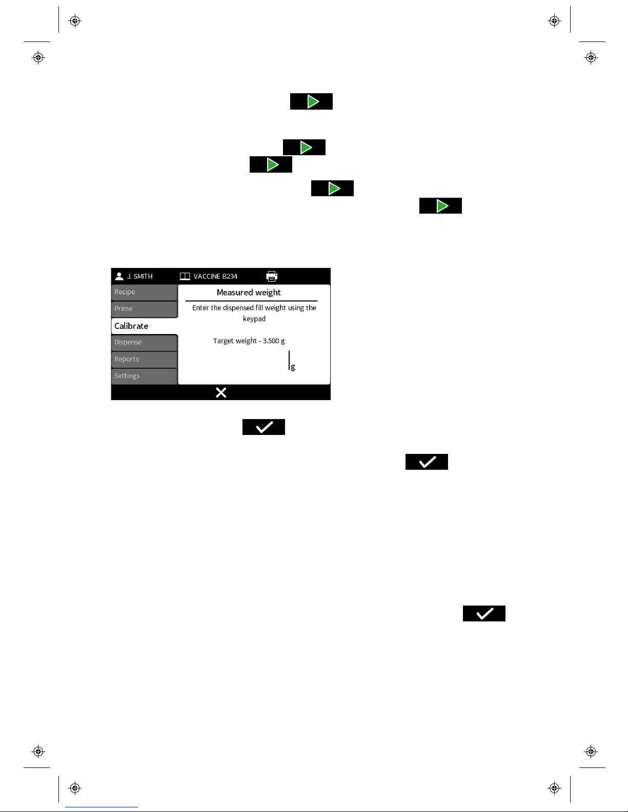
Calibration value entry
If not using a balance connected to the pump, enter the dispensed value using the
numeric keypad and press .
If a balance is connected to the pump, the balance value will be automatically
displayed. Place the filled bottle(s) on the balance and press .
If a multi-fill calibration has been performed, the entered value should be the total
value of all fills.
Calibration outside an acceptable level
If the calibration value entered is outside of the acceptable calibration range a
warning screen will be displayed.
Calibration summary
A calibration summary will be displayed. If the values are correct, press to
complete the calibration process.
Page 21
6.9 Dispense Mode
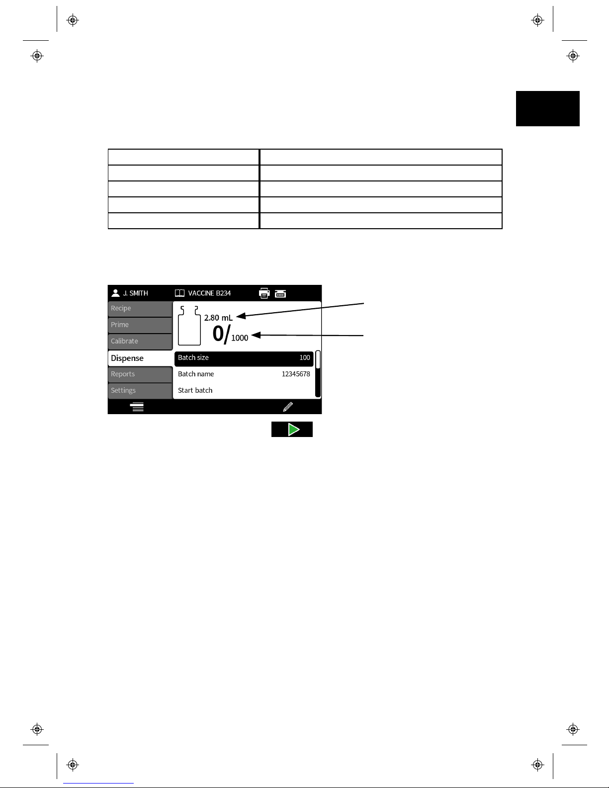
Within the Dispense menu it is possible to start a batch, define the size of the batch
required, give the batch a unique name and carry out a test fill.
Dispense item Description
Batch size Enter the number of fills to be done in the batch
Batch name Name given to the batch
Start batch Starts the batch
Test fill Dispense a single fill without creating a batch report
Before a batch is dispensed, ensure that your recipe items are correct, your pump
has been primed, calibrated and any additional settings are correct for your
process.
Target volume
Batch Progress icon:
The left hand number
is the number of
dispenses completed,
the right hand number
is the batch size
If Start batch is highlighted press to start the batch. If reporting is On, a
batch report will be created.
How the fills are started depends on the selected filling method.
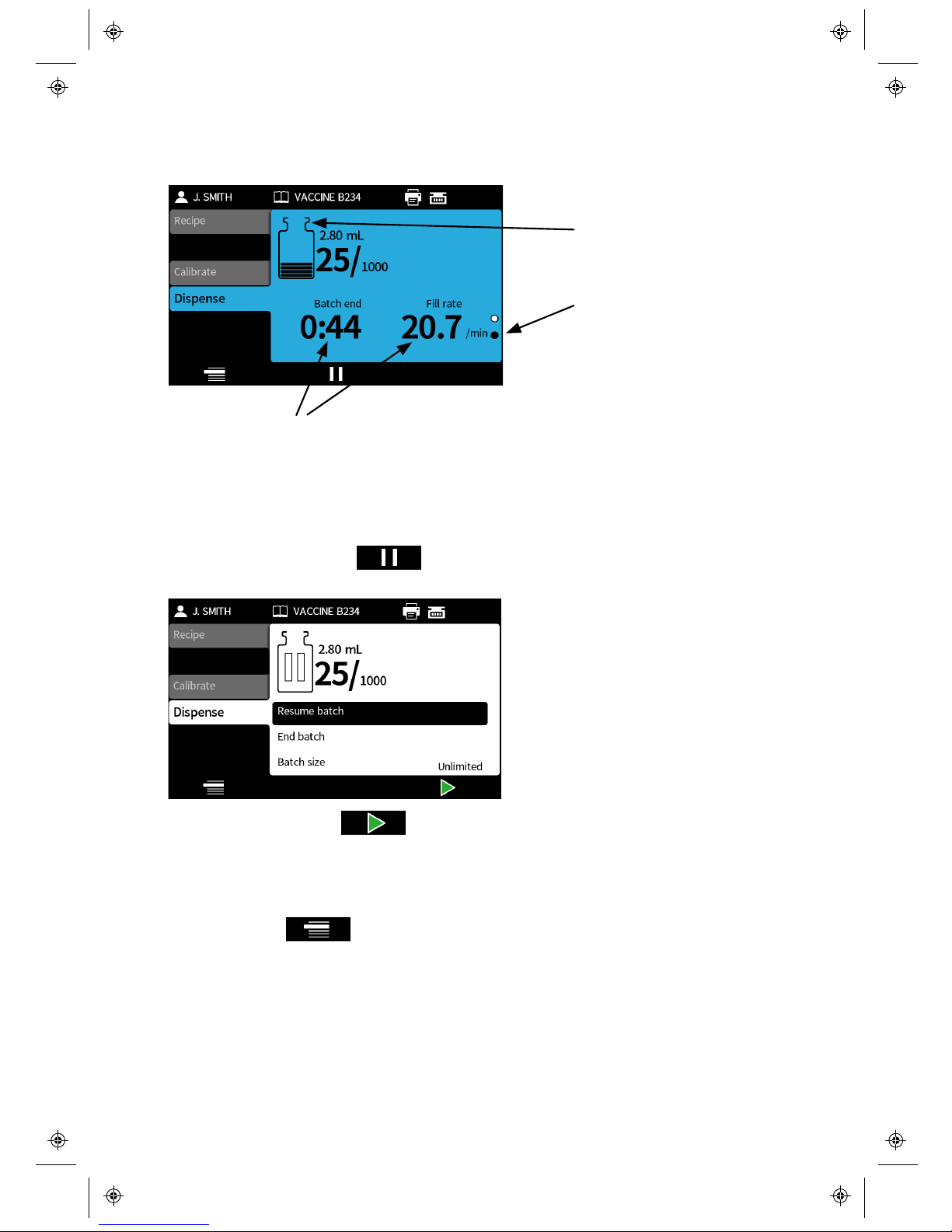
When the pump is dispensing or ready to dispense, the screen background colour
is blue.
m-PF7-Peristaltic Filler User
Manual-02:PB0439/2
21
EN EN EN EN EN EN EN EN EN EN EN EN EN EN EN EN EN
Page 22
22
m-PF7-Peristaltic Filler User
Manual-02:PB0439/2
If the stop key is pressed at any point, the pump will stop immediately and a fill
interrupt screen will be displayed.
Dispense icon
Page indicator icon
Batch information
Use the up and down keys (∧/∨) to change the information that is displayed whilst a
batch is running.
Pausing a batch
To pause a batch press . Once the current fill has been completed, the
batch will pause.
To resume filling press .
Recipe changes whilst dispensing
It is possible to change a selection of recipe items (if active in the recipe tab) during
a batch. Press to access recipe mode, this can be done regardless of
whether the batch is filling or paused.
Page 23
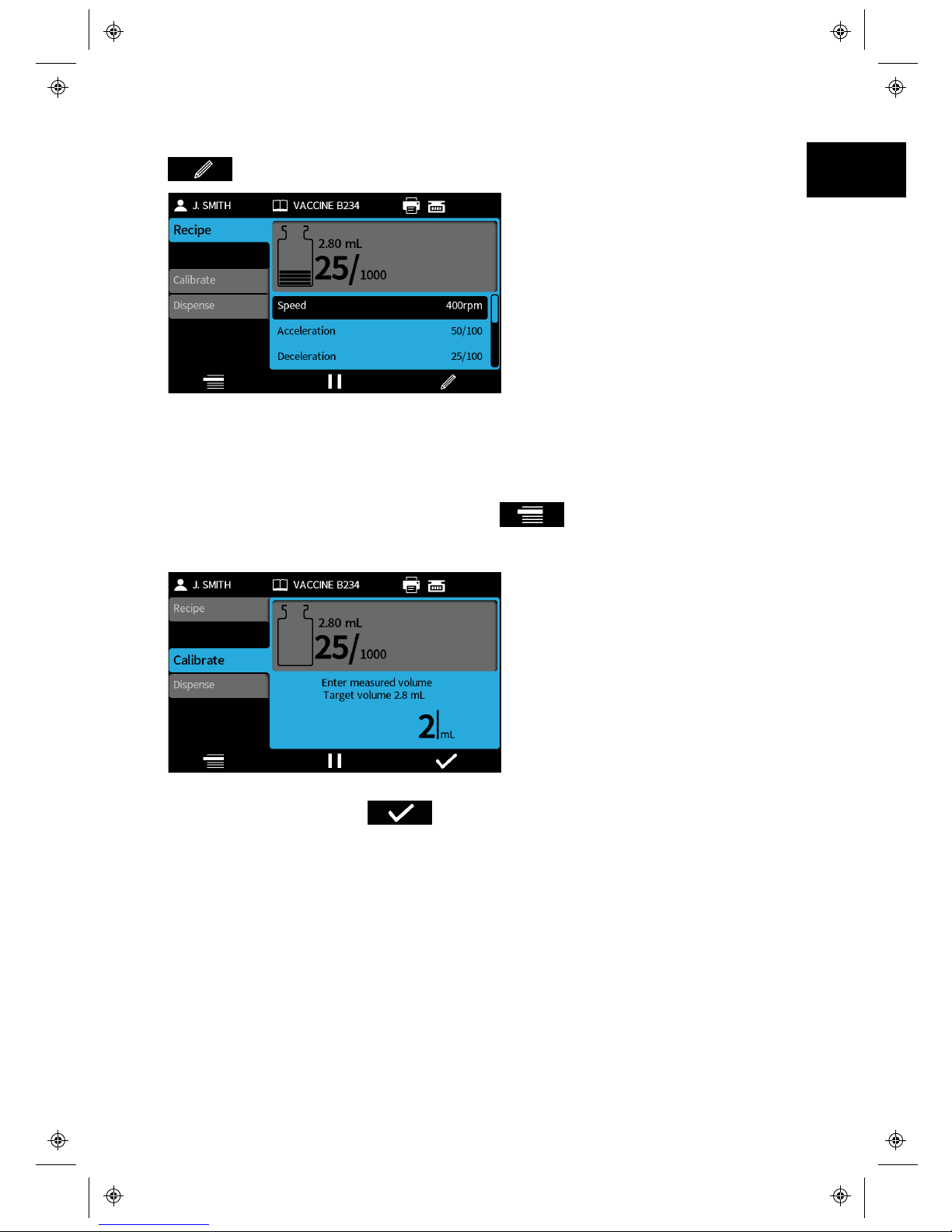
Navigate through the recipe items using the up and down arrows (∧/∨) and press
to edit the value.
If a recipe item is changed, the new value will be used for the next fill. If reporting
is On, any changes will be included in the batch report.
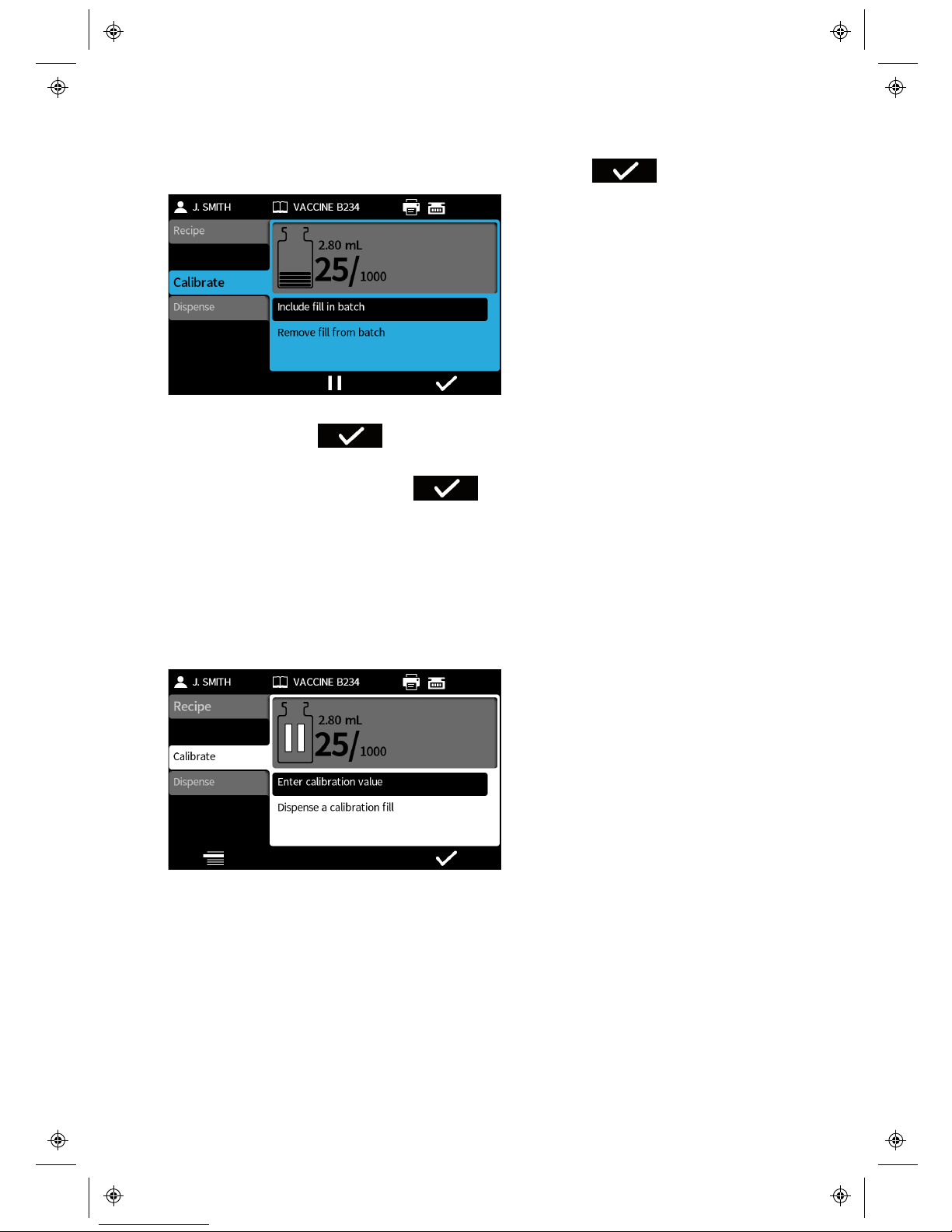
Calibration whilst dispensing
To calibrate the pump whilst filling, press to access calibrate mode. If
using a balance, ensure it was tared (set to zero) using the bottle to be filled before
filling.
If not using a balance connected to the pump, enter the calibration value using the
numeric keypad and press .
m-PF7-Peristaltic Filler User
Manual-02:PB0439/2
23
EN EN EN EN EN EN EN EN EN EN EN EN EN EN EN EN EN
Page 24
24
m-PF7-Peristaltic Filler User
Manual-02:PB0439/2
If a balance is connected to the pump, the balance value will be automatically
displayed. Place the filled bottle on the balance and press .
If the bottle used for calibration should be included in the batch, highlight Include
in batch and press .
If the bottle used for calibration should not be included in the batch, highlight
Remove from batch and press . A fill will then be removed from the total
completed.
If reporting is On, the new calibration value will be included in the batch report.
Calibration whilst paused
If the batch is paused and calibrate mode is accessed, either the calibration value
can be entered without filling, or a calibration fill can be dispensed before the
calibration value is entered.
Page 25
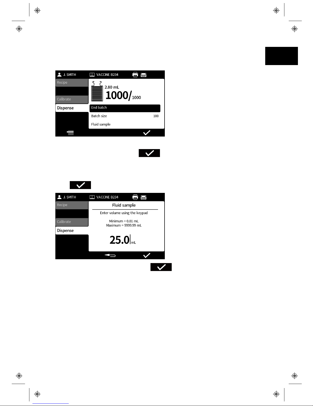
Ending a batch
If a Batch size has been entered, the batch will pause automatically when the
number of fills completed equals the batch size.
If End batch is highlighted press to end the batch. If reporting is On, the
batch report will be completed.
Fluid sample
To take a fluid sample. Pause the batch, highlight Fluid sample and
Press .
Enter the desired value and press . The fluid sample can then be
dispensed.
m-PF7-Peristaltic Filler User
Manual-02:PB0439/2
25
EN EN EN EN EN EN EN EN EN EN EN EN EN EN EN EN EN
Page 26
26
m-PF7-Peristaltic Filler User
Manual-02:PB0439/2
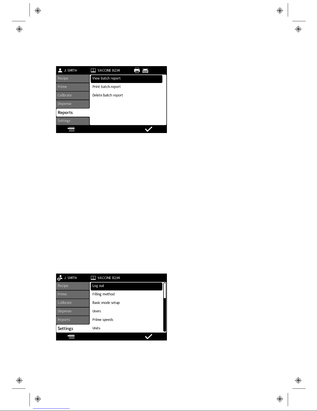
6.10 Reports mode
Batch reports can be viewed, printed or deleted from the reports tab.
The report data stored and output by the PF7 are the values for the following:
l Software Version l Tube size
l Batch number - unique ID l Acceleration
l Start time and date l Deceleration
l User name l Anti-drip
l Batch name l Start delay
l Recipe name l End delay
l Volume l Between fill delay
l Density l Batch size
l Calibration values when reporting is
turned on
l Speed
l Recipe setting changes while
dispensing, when reporting is turned on
6.11 Settings mode
The Settings menu gives the user access to a number of general settings, navigate
through the items using the up and down keys (∧/∨).
The full settings list is as follows:
Page 27
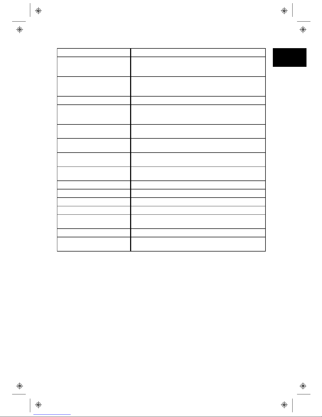
Settings item Description
Log out Selecting log out will return the pump to the Log in
screen seen after a power cycle. The user PIN wi ll nee d
to be entered if set to Log in.
Filling method How each fill is started. Either; Time delay between fills,
Key press to start each fill or External input to start
each fill.
Basic mode setup Set which functions are availabl e to users.
Users Setti ng up new pump users, editing existing pump users
and deleting users. Users can be set as either Users or
Administrators.
Prime speeds Setting the prime slow, prime fast and fluid recovery
speed levels.
Units Selecting the desired units for recipe and cal ibration
modes.
First calibration value Select how much of the recipe volume should be
dispensed duri ng the first cali bration fill.
Reporting Allowing the setting on or off, for the following;
reporting, auto-printing and auto-dele ting.
Default recipe Setting up the default recipe va lues.
Printer and balance List of printers and balances supported by the PF7.
Language Language selection.
Time and date Setting the time and date.
Pump info Software version, pump run hours, website and model
number.
Sound level Setting sound volumes.
Backup and reset Allowing the deleting of all recipes, the deleting of all
reports or carry out a factory reset.
Log out
A user can log in and out of the pump to give security when the pump is
unattended. If Log out is selected the pump will display the log in screen.
m-PF7-Peristaltic Filler User
Manual-02:PB0439/2
27
EN EN EN EN EN EN EN EN EN EN EN EN EN EN EN EN EN
Page 28
28
m-PF7-Peristaltic Filler User
Manual-02:PB0439/2
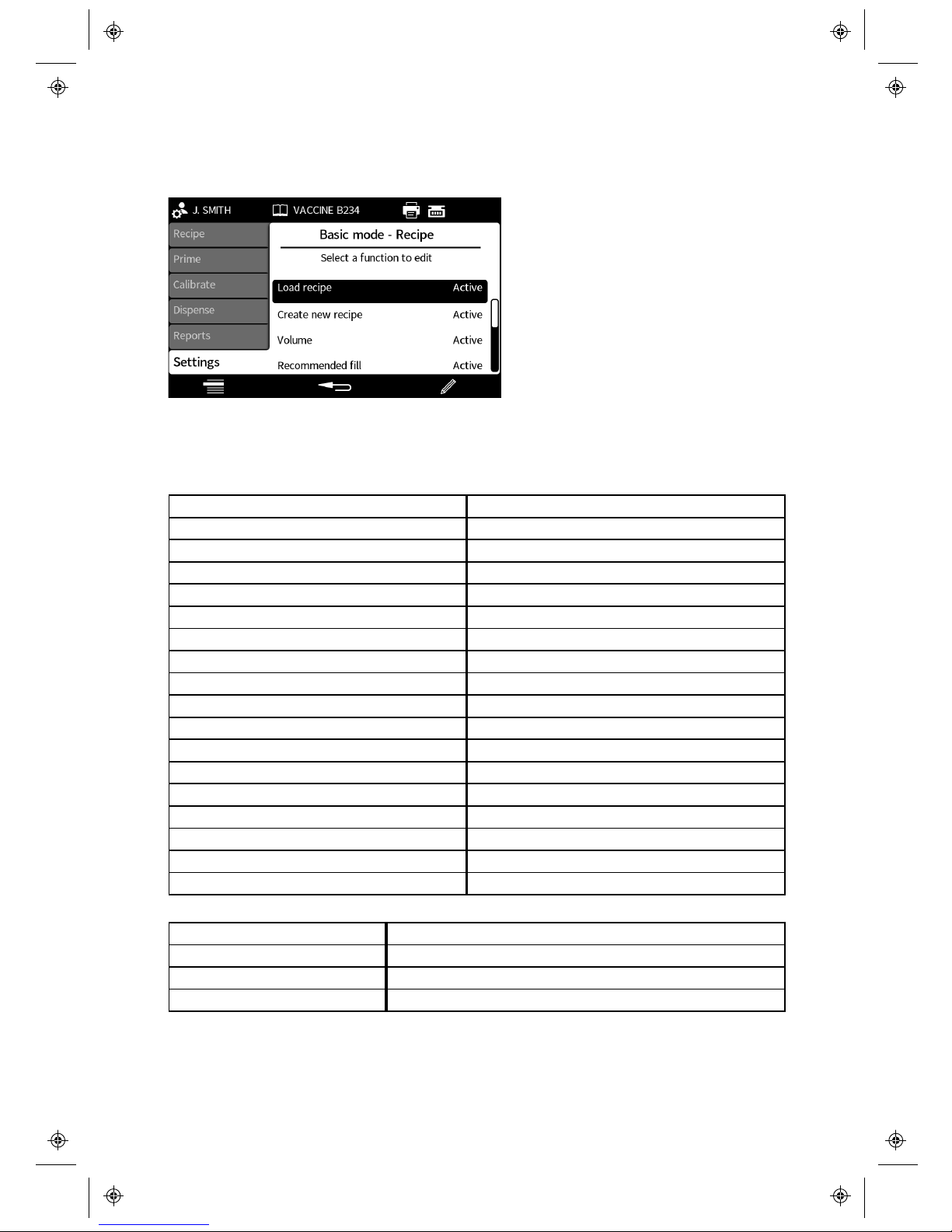
Basic mode setup
Basic mode setup allows an administrator to customise each menu tab for users.
Each menu tab can be active or hidden. Some items can also be customised as view
only. When an item is selected as active, the item is both viewable and editable.
The options for each tab item are shown in the tables below:
Recipe tab item Description
Load recipe Active/hidden
Create new recipe Active/hidden
Volume Active/view only/hidden
Density Active/view only/hidden
Tube size Active/view only/hidden
Velocity Active/view only/hidden
Acceleration Active/view only/hidden
Deceleration Active/view only/hidden
Anti-drip Active/view only/hidden
Start delay / First fill delay Active/view only/hidden
End delay / Between fill delay Active/view only/hidden
Recalibration reminder Active/view only/hidden
Recalibration pause Active/view only/hidden
Recipe editable Active/view only/hidden
Save recipe Active/hidden
Print recipe Active/hidden
Delete recipe Active/hidden
Prime tab item Description
Prime slow Active/hidden
Prime fast Active/hidden
Continuous pump Active/hidden
Page 29
Calibrate tab item Description
Single-fill calibration Active/hidden
Multi-fill calibration Active/hidden
Dispense tab item Description
Test fill Active/hidden
Index filling machine Active/hidden
Reports tab item Description
Print Active/hidden
View Active/hidden
Delete Active/hidden
Settings tab item Description
Filling method Active/hidden
Units Active/hidden
Language Active/hidden
Backup and reset
The backup and reset functions allow the user to delete all recipes, delete all
reports or carry out a factory reset.
If a factory reset is performed the pump will erase all customised settings, recipes
and reports and reset the pump to factory settings.
m-PF7-Peristaltic Filler User
Manual-02:PB0439/2
29
EN EN EN EN EN EN EN EN EN EN EN EN EN EN EN EN EN
Page 30
30
m-PF7-Peristaltic Filler User
Manual-02:PB0439/2
7 Setting up the fluid path
7.1 Tube selection
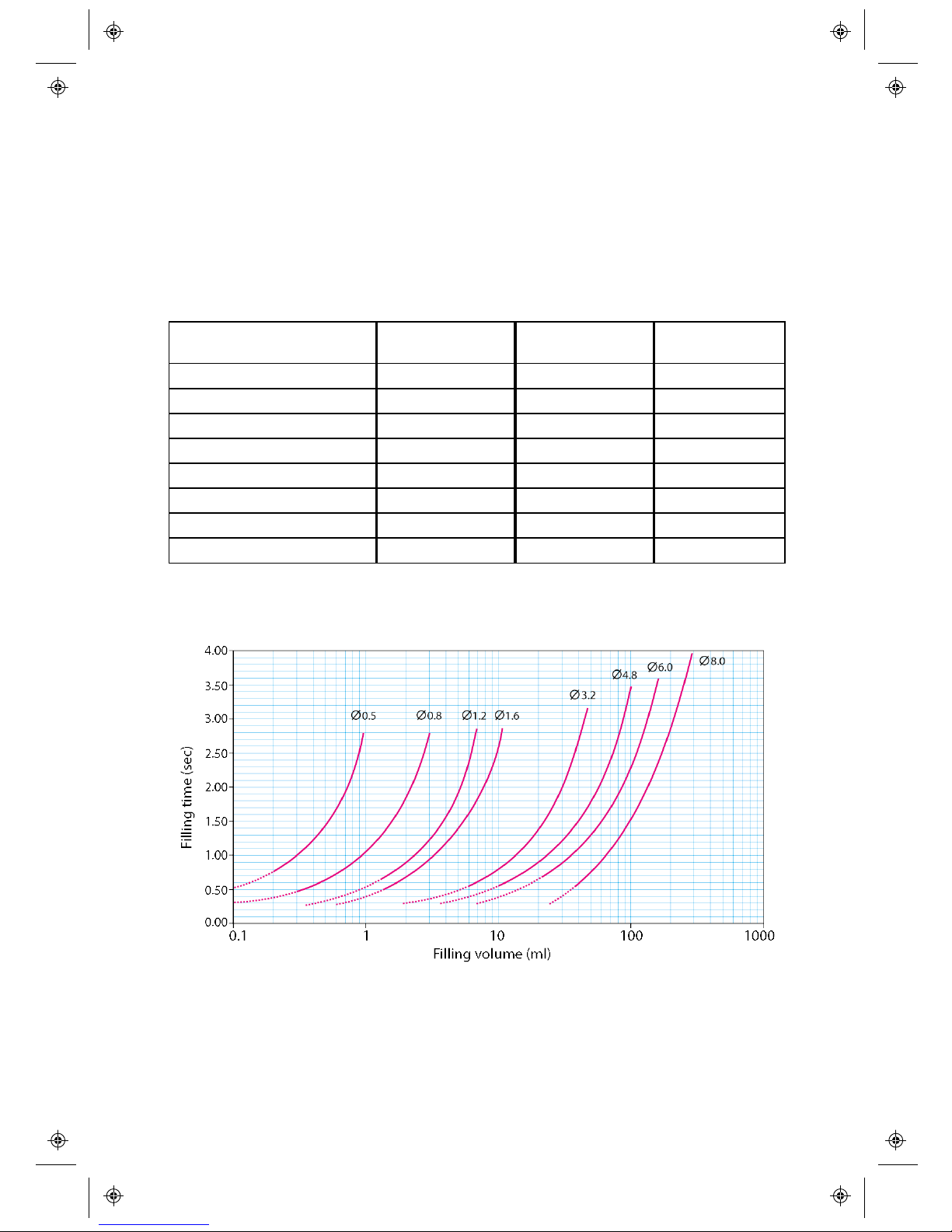
Tubes must be selected according to the application and volume to be filled. Use the
table shown below for choice of tubes according to minimum volume to be filled.
In order to obtain stable and good results, the choice of tubing can be made
according to the following guideline:
Volume (ml) Filling Nozzle
(mm i.d.)
Tubing
(mm i.d.)
Y-Connector
(mm i.d.)
<0.50 0.6 0.5 1.2
0.50 - 1.00 1.0 0.8 1.2
1.00 - 1.70 1.0 1.2 1.8
1.70 - 7.00 1.6 1.6 1.8
7.00 - 12.0 3.2 3.2 3.6
12.0 - 22.0 4.5 4.8 4.8
22.0 - 35.0 6.0 6.0 4.8
> 35.0 8.0* 8.0 7.5
* use non-return valve
Page 31
7.2 Placing the product container
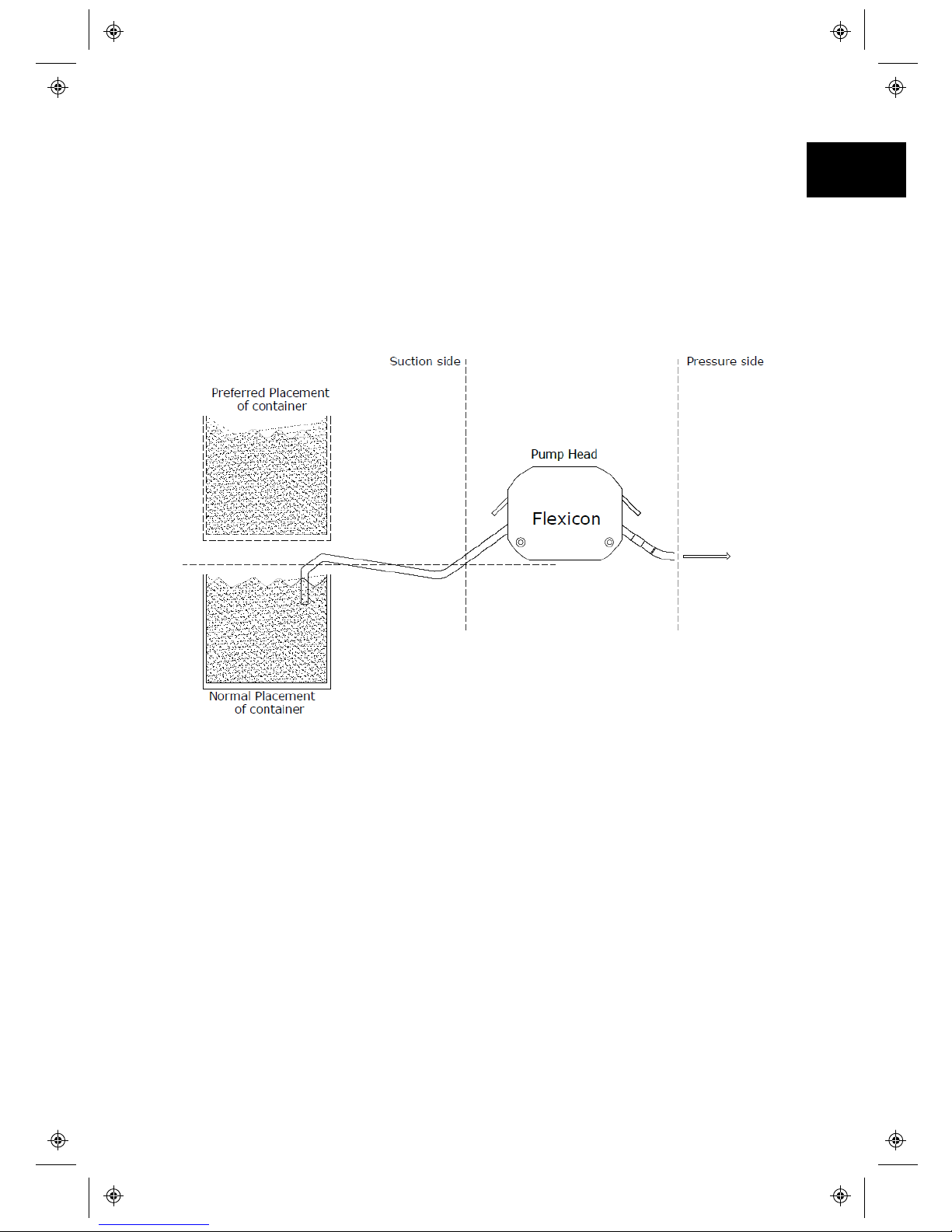
In order to get an optimal filling; i.e. best accuracy, long periods between each
calibration and the best capacity, the product container should be placed at the
same level as pump head or preferably above the pump head level. The length
between container, pump head and filling nozzle must be as short as possible.
Placing the container higher than pump head level provides positive product
support and may reduce the calibration interval. It is also recommended to place
the container as close as possible to the pump on suction side.
Ensure there are no tight bends or obstructions which could reduce the fluid flow in
the tube line.
m-PF7-Peristaltic Filler User
Manual-02:PB0439/2
31
EN EN EN EN EN EN EN EN EN EN EN EN EN EN EN EN EN
Page 32
32
m-PF7-Peristaltic Filler User
Manual-02:PB0439/2
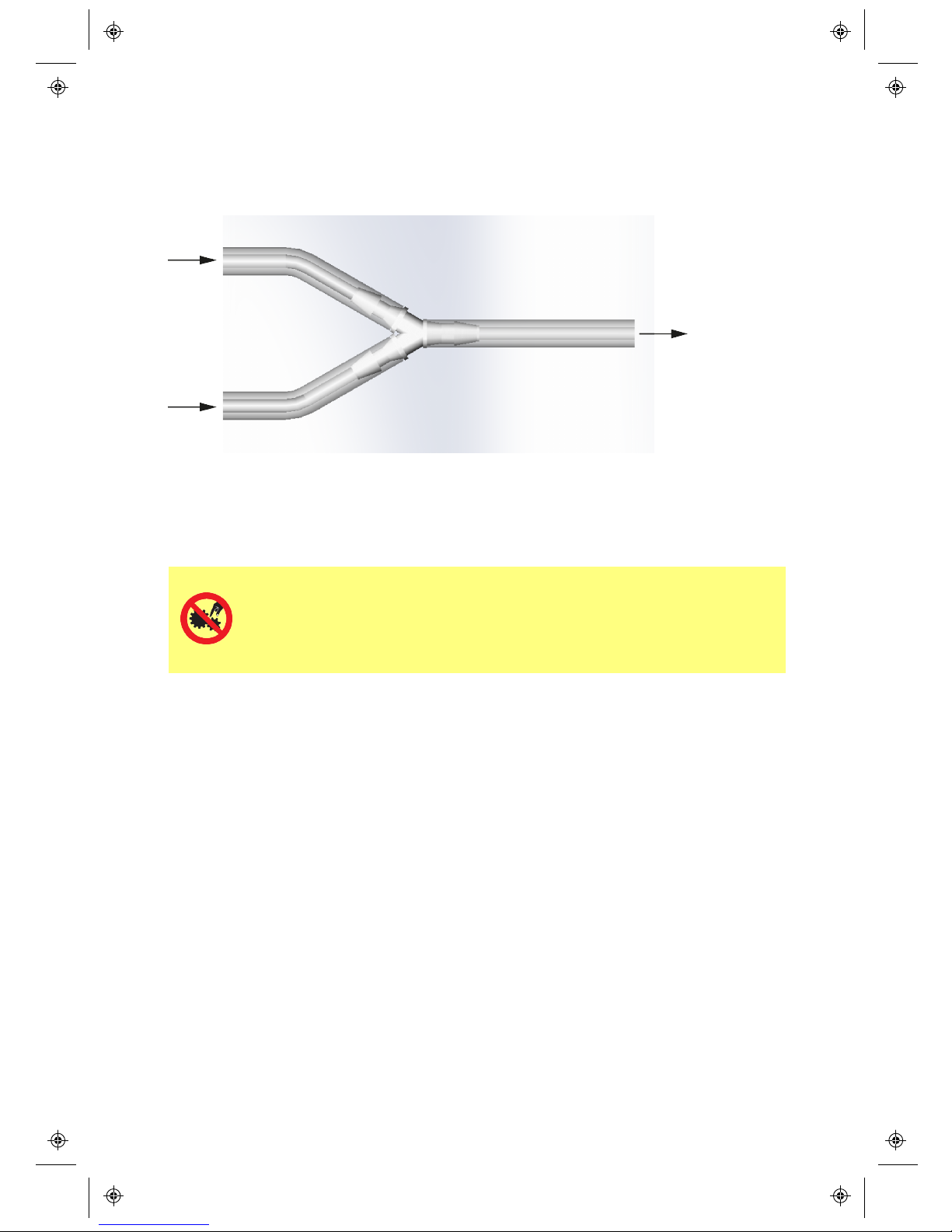
7.3 Y-connector selection
Before mounting the tubes in the dispenser head the tubes must be assembled with
a Y-connector.
When the Y-connector has been assembled, mount the tubes in the dispenser head
as shown below.
7.4 Loading the tube
Primary operator protection from rotating parts of this pump is
provided by isolating the pump from mains power before opening the
pump head tube bridge. The pump also provides a tube bridge open
indicator. If the tube bridge is opened, the tube bridge open screen is
displayed.
Page 33
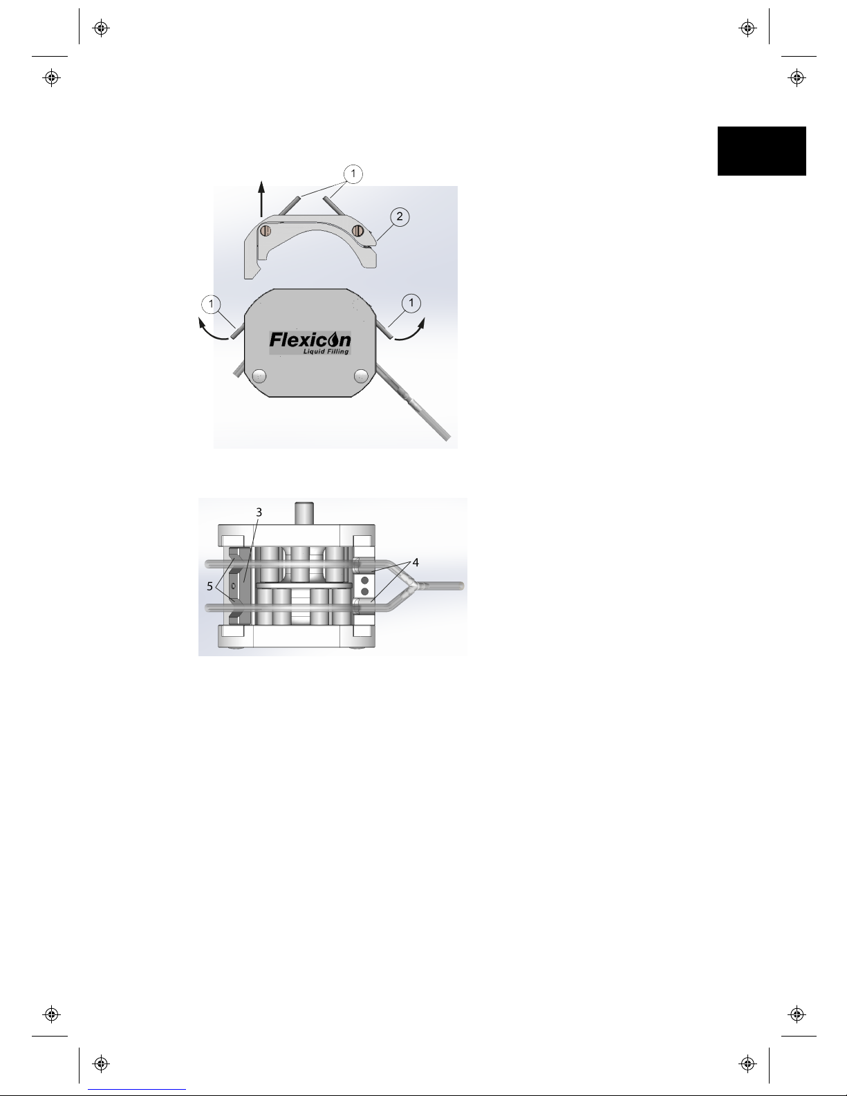
1. Open the dispenser head by lifting each of the two locking levers up (1) and
lift the tube bridge (2).
2. Mount the correct tube lock (3) on its dowel pin and place the correct tubes
in the dispenser head.
3. Looking towards the pump head from the front. The Y-connector must be
situated to the right of the dispenser head.
It is important that the tubes are situated in the two notches (4+5).
4. Place the tube bridge (2) in its tracks and press down the two locking levers
(1).
Never leave the dispenser mounted with tubes overnight.
At least lift the locking levers (1) up in order to relieve the pressure in the
tube.
m-PF7-Peristaltic Filler User
Manual-02:PB0439/2
33
EN EN EN EN EN EN EN EN EN EN EN EN EN EN EN EN EN
Page 34

34
m-PF7-Peristaltic Filler User
Manual-02:PB0439/2
8 Good pump installation practice
8.1 General recommendations
It is recommended that the pump is sited on a flat, horizontal, rigid surface, free
from excessive vibration, to ensure the correct pumphead operation. Allow a free
flow of air around the pump to ensure that heat can be dissipated. Ensure that the
ambient temperature around the pump does not exceed the recommended
maximum operating temperature.
Peristaltic pumps are self-priming and self-sealing against backflow. No valves are
required in inlet or discharge line, except those specified as below.
8.2 Dos and don'ts
l Do not build a pump into a tight location without adequate airflow around the
pump.
l Do keep delivery and suction tubes as short and direct as possible - though
ideally not shorter than one metre - and follow the straightest route. Use bends
of large radius: at least four times the tubing diameter. Ensure that connecting
pipework and fittings are suitably rated to handle the predicted pipeline
pressure. Avoid pipe reducers and lengths of smaller bore tubing than the
pumphead section, particularly in pipelines on the suction side. Any valves in the
pipeline must not restrict the flow. Any valves in the flow line must be open when
the pump is running.
l Do ensure that on longer tube runs at least one metre of smooth bore, flexible
tubing is connected to the inlet and discharge port of the pumphead to help to
minimise impulse losses and pulsation in the pipeline. This is especially
important with viscous fluids and when connecting to rigid pipework.
l Do use suction and delivery pipes equal to or larger than the tubing diameter
bore. When pumping viscous fluids use pipe runs with a bore several times
larger than the pump tube.
l Do site the pump at or just below the level of the fluid to be pumped if possible.
This will ensure flooded suction and maximum pumping efficiency.
l Do run at slow speed when pumping viscous fluids. Flooded suction will enhance
pumping performance, particularly for materials of a viscous nature.
l Do recalibrate after changing tubing, fluid or any connecting pipework. It is also
recommended that the pump is recalibrated periodically to maintain accuracy.
l Do not pump any chemical not compatible with the tubing or pumphead.
l Do not run the pump with no tube or element fitted to the pumphead.
l Do not strap the control and mains cable together.
Page 35
9 Connecting to a power supply
A well regulated electrical mains supply is required along with cable connections
conforming to the best practice of noise immunity. It is not recommended to site
these drives alongside 'dirty' electrical mains devices, such as 3-phase contactors
and inductive heaters without special attention being paid to unacceptable mainsborne noise. Make suitable connection to an earthed single-phase mains electricity
supply.
The PF7 uses a standard IEC socket and a country specific cord set. Ensure that all
power supply cables are adequately rated for the equipment.
Set the voltage selector to 115V for 100-120V 50/60Hz supplies or
230V for 200-240V 50/60Hz supplies. Always check the voltage
selector switch before connecting to the mains supply or the pump
will be damaged.
m-PF7-Peristaltic Filler User
Manual-02:PB0439/2
35
EN EN EN EN EN EN EN EN EN EN EN EN EN EN EN EN EN
Page 36
36
m-PF7-Peristaltic Filler User
Manual-02:PB0439/2
10 Control wiring
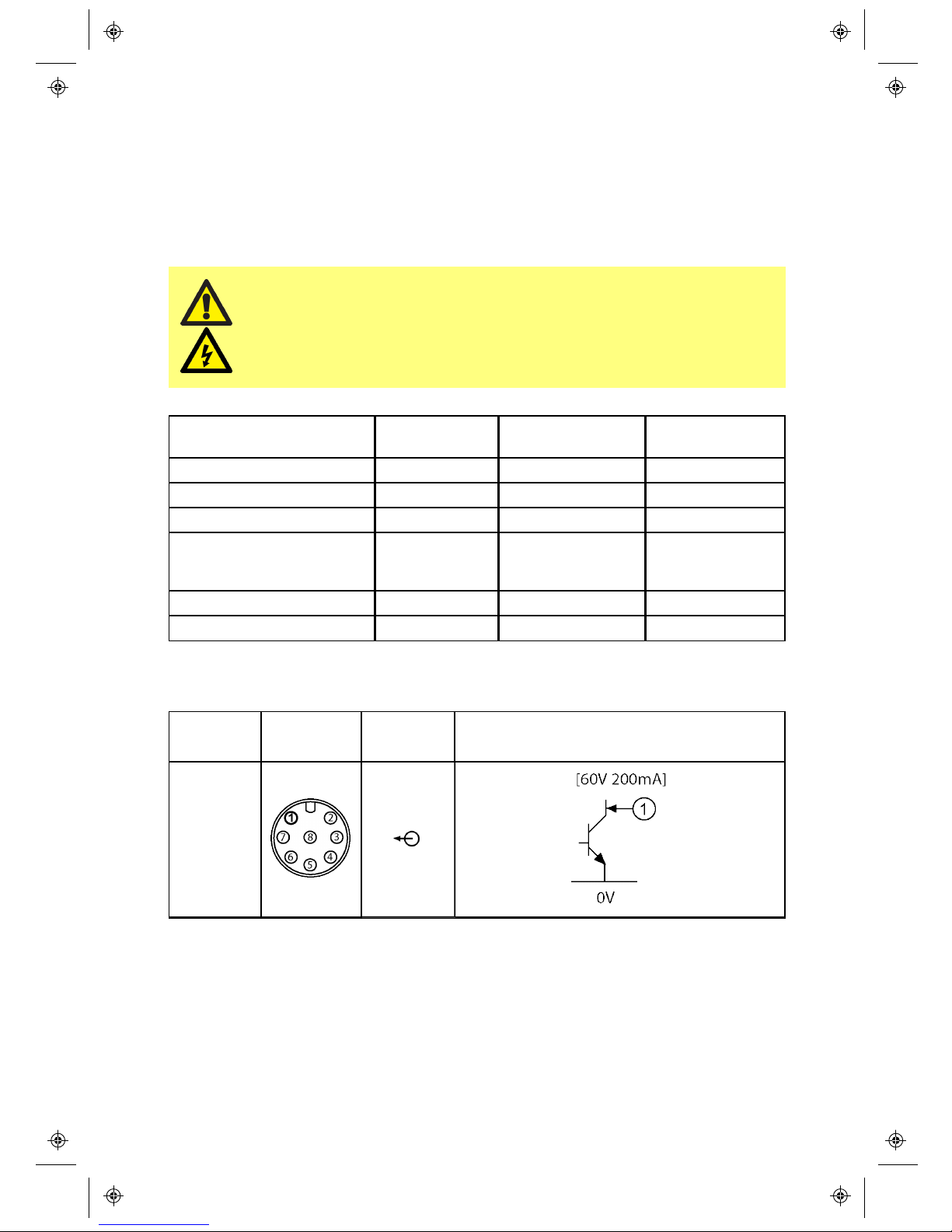
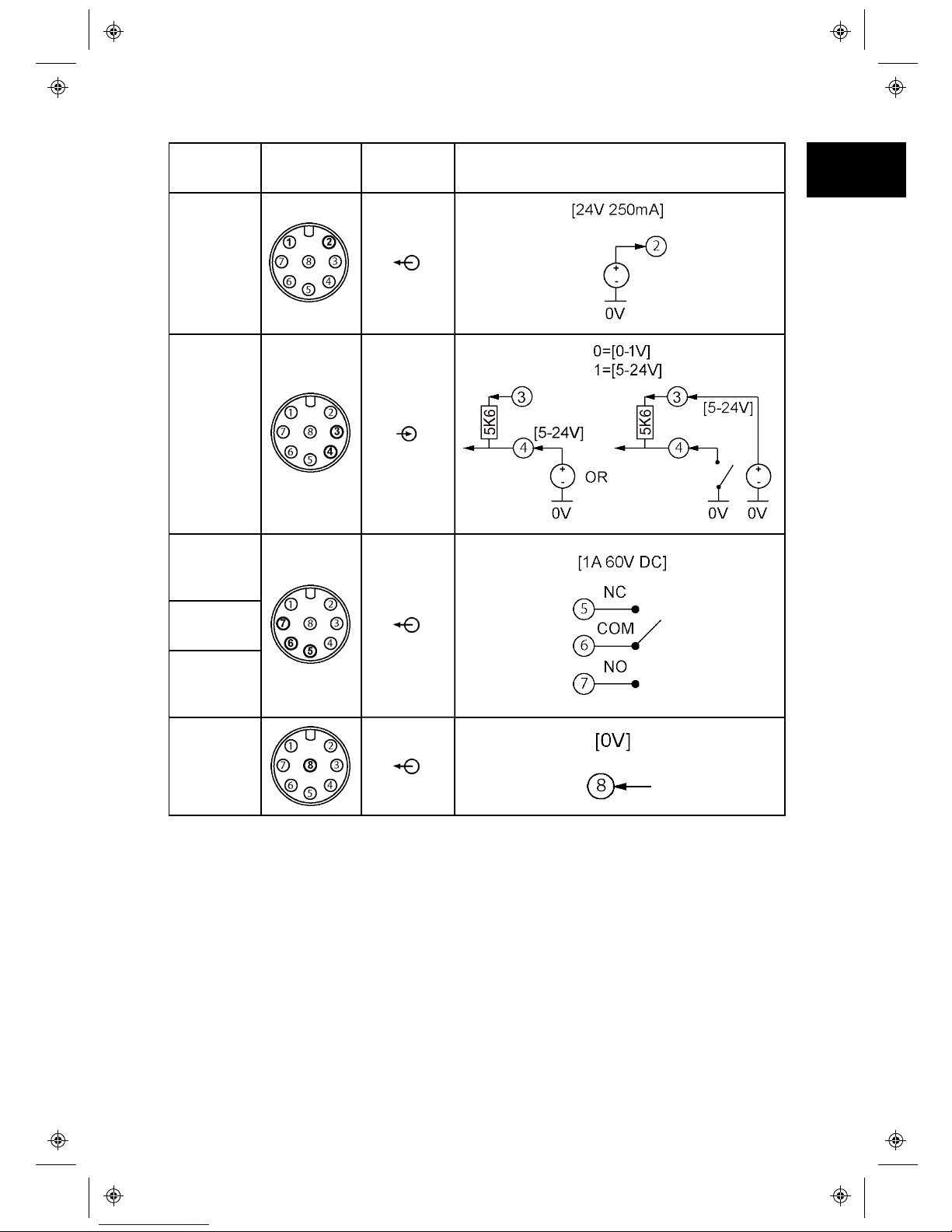
There are two off, M12 8-pin connectors on the rear of the PF7 unit; these contain
pins that allow both inputs and outputs. Both connectors have the same pin
configuration. The use of each pin is shown in the tables below, along with the pin
function and the signal response.
Never apply mains power to the M12 connectors. Apply the correct
signals to the pins shown. Limit signals to the maximum values
shown. Do not apply voltage across other pins. Permanent damage,
not covered by warranty, may result.
Pin Type Pin(s) CONNECTOR 1
Functionality
CONNECTOR 2
Functionality
Input 4 Start (5-24V) Prime (5-24V)
Input pull-up 3
Volta ge output (24V) 2 Active Active
Discrete output (Open
Drain)
1 Active when filling
(Start delay +
filling + end delay)
Inactiv e when
filling
Relay output 5, 6 & 7 Gene ral error Paused
Ground 8
Function
Pin
number
Input/
Output
Signal respons e
Discrete
Output
(Open
Drain)
Page 37
Function
Pin
number
Input/
Output
Signal respons e
Volta ge
Output
(24V)
Input
Relay
(Normally
Closed)
Relay
(Common)
Relay
(Normally
Open)
Signal and
Power
Return
m-PF7-Peristaltic Filler User
Manual-02:PB0439/2
37
EN EN EN EN EN EN EN EN EN EN EN EN EN EN EN EN EN
Page 38
38
m-PF7-Peristaltic Filler User
Manual-02:PB0439/2
11 Pump specifications
11.1 Specification ratings
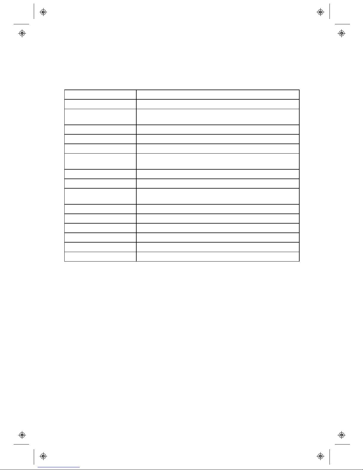
Operating temperature 5C to 40C (41F to 104F)
Storage temperature
-40C to 70C (-40F to 158F)
Humidity (noncondensing)
80% up to 31C (88F) decreasing linearly to 50% at 40C
(104F)
Maximum alti tude 2000m (6560ft)
Power consumption
140VA
Supply volta ge Filtered 100-120V/200-240V 50/60Hz 1pH
Maximum voltage
fluctuation
+/-10% of nominal voltage.
Full load current
<0.6A@ 230V; <1.25A @ 115V
Fuse rating
Ceramic, 5x20mm, 2.5A, 250V AC, Time Delay
Installation category
(overvoltage category)
II
Pol lution degree 2
IP IP32 to BS EN 60529
dB rating
<70dB (A) @ 1m
Control ratio
30-400rpm (3700:1)
Maximum spe ed
400rpm
Weight 12.5kg
Page 39

12 Troubleshooting
If the pump display remains blank when the pump is switched on, make
the following checks:
• Check that the mains power is available to the pump.
• Check the fuse in the wall plug if one is present.
• Check the position of the voltage selector switch.
• Check the mains power switch at the rear of the pump.
• Check the fuse holder in the centre of the switch plate at the rear of the pump.
If the pump runs but there is little or no flow, make the following
checks:
• Check that fluid is supplied to the pump.
• Check for any kinks or blockages in the lines.
• Check that any valves in the line are open.
• Check that the tube and rotor are in the pumphead.
• Check that a tube is not split or burst.
• Check that the correct wall-thickness tube is being used.
• Check the direction of rotation.
• Check that the rotor is not slipping on the drive shaft.
m-PF7-Peristaltic Filler User
Manual-02:PB0439/2
39
EN EN EN EN EN EN EN EN EN EN EN EN EN EN EN EN EN
Page 40
40
m-PF7-Peristaltic Filler User
Manual-02:PB0439/2
13 Pump maintenance (including cleaning)
13.1 Service
There are no user serviceable parts inside the pump. The unit should be returned
to a Watson Marlow Ltd or Flexicon approved service centre for service. For any
additional service requirements, including help with scheduled maintenance of
pump heads when included with any system please contact your nearest Watson
Marlow Ltd or Flexicon representative.
13.2 Cleaning
Always isolate the pump from the mains power supply before opening
any guard or track, or performing any positioning, removal or
maintenance operation.
Remove the tube bridge and the tubes before cleaning the pump.
Acceptable cleaning agents
regime
Cleaning precautions
Hydrogen peroxide vapour Please follow all the Safety Data Sheet
(MSDS) precautions.
Ethyl Alcohol 70% Please follow all the Safety Data Sheet
(MSDS) precautions.
Surface disinfectant containing
Formaldehyde
Please follow all the Safety Data Sheet
(MSDS) precautions.
6% concentration of hydrogen
peroxide in water for injection
(WFI)
Please follow all the Safety Data Sheet
(MSDS) precautions.
13.3 Pumphead Removal
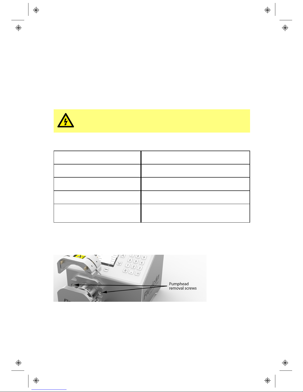
To remove the pumphead from the PF7, remove the tube bridge. Using a 5mm Hex
key, remove the two pumphead mounting screws as shown below.
Page 41

14 Warranty
Watson-Marlow Limited ("Watson- Marlow") warrants this product on behalf of
Flexicon to be free from defects in materials and workmanship for five years from
the date of shipment, under normal use and service.
Watson-Marlow's sole responsibility and the customer's exclusive remedy for any
claim arising out of the purchase of any product from Watson-Marlow is, at WatsonMarlow's option: repair, replacement or credit, where applicable.
Unless otherwise agreed in writing, the foregoing warranty is limited to the country
in which the product is sold.
No employee, agent or representative of Watson-Marlow has the authority to bind
Watson-Marlow to any warranty other than the foregoing unless in writing and
signed by a director of Watson-Marlow. Watson-Marlow makes no warranty of the
fitness of its products for a particular purpose.
In no event:
i. shall the cost of the customer's exclusive remedy exceed the purchase price
of the product;
ii. shall Watson- Marlow be liable for any special, indirect, incidental,
consequential, or exemplary damages, however arising, even if WatsonMarlow has been advised of the possibility of such damages.
Watson-Marlow shall not be liable for any loss, damage, or expense directly or
indirectly related to or arising out of the use of its products, including damage or
injury caused to other products, machinery, buildings, or property. Watson-Marlow
shall not be liable for consequential damages, including without limitation, lost
profits, loss of time, inconvenience, loss of product pumped, and loss of
production.
This warranty does not obligate Watson-Marlow to bear any costs of removal,
installation, transportation, or other charges which may arise in connection with a
warranty claim.
Watson-Marlow shall not be responsible for shipping damage of returned items.
Conditions
oProducts must be returned by pre-arrangement to Watson-Marlow, or a Watson-
Marlow or Flexicon approved service centre.
oAll repairs or modifications must have been made by Watson- Marlow, or a
Watson- Marlow or Flexicon approved service centre or with the express
permission in writing of Watson- Marlow, signed by a manager or director of
Watson-Marlow.
oAny remote control or system connections must be made in accordance to
Watson-Marlow recommendations.
Exceptions
oConsumable items including tubing and pumping elements are excluded.
oPumphead rollers are excluded.
oRepairs or service necessitated by normal wear and tear or by lack of reasonable
and proper maintenance are excluded.
m-PF7-Peristaltic Filler User
Manual-02:PB0439/2
41
EN EN EN EN EN EN EN EN EN EN EN EN EN EN EN EN EN
Page 42

42
m-PF7-Peristaltic Filler User
Manual-02:PB0439/2
oProducts which, in the judgement of Watson- Marlow, have been abused,
misused, or subject to malicious or accidental damage or neglect are excluded.
oFailure caused by electrical surge is excluded.
oFailure caused by incorrect or sub-standard system wiring is excluded.
oDamage by chemical attack is excluded.
oAncillaries such as leak detectors are excluded.
oFailure caused by UV light or direct sunlight.
oAny attempt to disassemble a Watson-Marlow product will invalidate the product
warranty.
Watson-Marlow reserves the right to amend these terms and conditions at any time.
15 Information for returning pumps
In compliance with the UK Health and Safety at Work Act and the Control of
Substances Hazardous to Health Regulations, you are required to declare the
substances which have been in contact with product (s) you return to WatsonMarlow Ltd or it subsidiaries or distributors. Failure to do so will cause delays.
Please ensure that you email us this information and receive a RGA (Returned Goods
Authorisation) before you despatch the product(s). A copy of the RGA form must be
attached to the outside of the packaging containing the product(s).
Please complete a separate decontamination certificate for each product and attach
it to the outside of the packaging containing the product (s). A copy of the
appropriate decontamination certificate can be downloaded from the WatsonMarlow Ltd website at www.wmftg.com
You are responsible for cleaning and decontaminating the product(s) before return.
16 Name and address of manufacturer
Watson Marlow Ltd
Falmouth, Cornwall
TR11 4RU
UK
Telephone: +44 (0) 1326 370370
Fax: +44 (0) 1326 376009
Email: [email protected]
www.wmftg.com
17 Disclaimers
The information contained in this document is believed to be correct but WatsonMarlow Ltd Fluid Technology Group accepts no liability for any errors it contains and
reserves the right to alter specifications without notice.
WARNING: This product is not designed for use in and should not be used for,
patient-connected applications.
 Loading...