

Page 1

INSTRUCTION HANDBOOK
FF20
FF20 IH EN 74-215-051 v1.02.doc Version: 1.02 Page 1 of 21
FF20
(example; exact model may vary)
This instruction handbook is for the daily users of the equipment.
Page 2

INSTRUCTION HANDBOOK
FF20
FF20 IH EN 74-215-051 v1.02.doc Version: 1.02 Page 2 of 21
1 Table of Contents
1 Table of Contents .................................................................................................................... 2
2 Introduction ............................................................................................................................. 3
2.1 FF20 ....................................................................................................................................... 3
2.2 Abbreviations in this manual ................................................................................................... 3
2.3 Symbols on the machine ......................................................................................................... 3
2.4 Caution and employee safety .................................................................................................. 4
2.5 Essential training before daily use ........................................................................................... 4
2.6 References ............................................................................................................................. 4
2.7 Dismantling and disposal ........................................................................................................ 4
3 General information ................................................................................................................. 5
3.1 Unpacking and inspection ....................................................................................................... 5
3.2 Receiving and storing the FF20............................................................................................... 5
3.3 Mounting of inlet and outlet trays ............................................................................................. 5
3.3.1 Side infeed .............................................................................................................................. 5
3.3.2 Front infeed ............................................................................................................................. 5
3.4 Mounting of filling stand .......................................................................................................... 8
3.5 Technical specifications .......................................................................................................... 9
3.5.1 Dimensions with front infeed ................................................................................................... 9
3.5.2 Dimensions with side infeed .................................................................................................. 10
3.5.3 Services ................................................................................................................................ 11
3.5.4 Bottles and trays ................................................................................................................... 11
3.5.5 Ingress protection ................................................................................................................. 11
3.5.6 Weight ................................................................................................................................... 11
3.5.7 Materials of construction ....................................................................................................... 11
3.5.8 Optional fillers and capping machines ................................................................................... 11
4 Installation ............................................................................................................................. 12
4.1 Connections .......................................................................................................................... 12
5 Control panel ......................................................................................................................... 13
6 Daily Use .............................................................................................................................. 14
6.1 Starting-up and running ......................................................................................................... 14
6.2 Adjustments .......................................................................................................................... 14
6.2.1 Adjusting the round table inner bottle rail .............................................................................. 14
6.2.2 Adjusting the bottle sluice...................................................................................................... 14
6.2.3 Adjusting the inlet sensor ...................................................................................................... 15
6.2.4 Adjustment of the filling stand ............................................................................................... 15
6.3 Production START and STOP ............................................................................................... 16
6.4 Stepping bottles .................................................................................................................... 16
6.5 Removing bottles from outlet / collection tray ........................................................................ 16
7 Malfunctioning ....................................................................................................................... 17
7.1 Function errors / Trouble shooting ......................................................................................... 17
8 Cleaning ................................................................................................................................ 18
8.1 Cleaning Frequency .............................................................................................................. 18
8.2 Preparations for cleaning ...................................................................................................... 18
8.3 Cleaning Guidance................................................................................................................ 18
8.4 Detergents or cleaning agents .............................................................................................. 18
9 Maintenance & service .......................................................................................................... 19
9.1 Maintenance ......................................................................................................................... 19
9.1.1 Tension of toothed belt .......................................................................................................... 19
9.1.2 Alignment of bottle disc (round table) .................................................................................... 19
9.1.3 Alignment of trays ................................................................................................................. 20
9.2 Service .................................................................................................................................. 20
9.3 Methods and frequency of inspections for safety functions .................................................... 20
10 Change of voltage ................................................................................................................. 20
11 Declaration of conformity....................................................................................................... 21
Page 3
INSTRUCTION HANDBOOK
FF20
FF20 IH EN 74-215-051 v1.02.doc Version: 1.02 Page 3 of 21
2 Introduction
All the photographs in the handbook are photo examples and may vary slightly from the exact model; i.e.
type of bottle used on the photograph, type and guiding on the inlet and outlet trays etc.
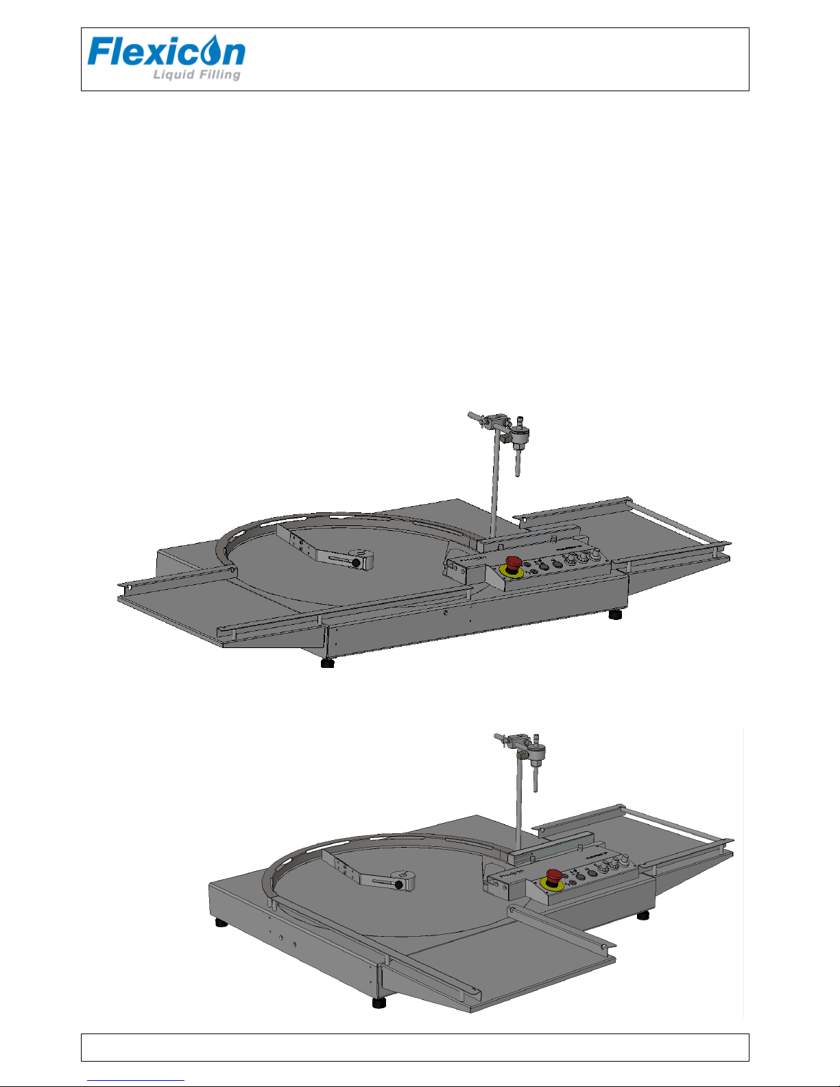
2.1 FF20
FlexFeed 20 is a rotary bottle handling system.
A rotary table moves the bottles from the inlet area to the bottle sluice, from which each bottle is moved
further on by a bottle pusher.
Filling is performed automatically when a bottle is present below the filling nozzle.
After filling, the bottle is pushed towards the outlet tray.
FF20 is delivered without an external filler.
In order to perform fillings, a filler must be connected. (See further information in section 3.5)
2.2 Abbreviations in this manual
App.
Approximately
e.g.
As example
Hz
Hertz
IH
Instruction Handbook
L/min
Litres per minute
Max.
Maximum
SOP
Standard Operating Procedure
VAC
Volt Alternating Current
WMF
Watson-Marlow Flexicon a/s
2.3 Symbols on the machine
Warning against touching Warning against high voltage
Page 4

INSTRUCTION HANDBOOK
FF20
FF20 IH EN 74-215-051 v1.02.doc Version: 1.02 Page 4 of 21
2.4 Caution and employee safety
This manual should be read before using the FF20.
It is strongly advised that:
• Power is disconnected and secured before any kind of maintenance or cleaning of the machine is
carried out.
• Unauthorised / non-trained personnel should not open any cover or maintain the electrical parts.
• The machine much be placed on a stable bed plate and in such a way, that it is not exposed to
high humidity, high temperatures or other abnormal operating environment. It is not to be used in
explosion hazardous environment.
• Always remember that the FF20 must be earthed through the power supply plug.
2.5 Essential training before daily use
Read the section with Daily Use, thoroughly before using the machine.
Protective equipment and protective devices are installed:
• If fingers are placed in front of the inlet bottle sensor, the bottle ejector will move automatically.
If the ejector meets too much resistance, it will return to start position.
• In manual mode the ejector will not move back.
To protect operator fingers from damage the railing is spring loaded so it will be pushed back.
• Always respect the warning symbols on the machine.
• Cleaning must be performed as described in this Instruction Handbook.
2.6 References
N/A
2.7 Dismantling and disposal
Prior to dismantling, it must be observed that all services are disconnected, and connections to other
equipment are removed.
WM-Flexicon machines may not be disposed using normal refuse collection.
The machines must be collected and disposed separately as they may contain
electrical components such as batteries, electrolyte capacitors, liquid crystal
displays and printed circuit boards.
Further information is available on www.wmflexicon.dk.
*
* (WEEE) DS/EN 50419
Page 5
INSTRUCTION HANDBOOK
FF20
FF20 IH EN 74-215-051 v1.02.doc Version: 1.02 Page 5 of 21
3 General information
3.1 Unpacking and inspection
Please check that all ordered items have been received and that no items are damaged during transport.
In case of any defects or omissions, please contact WMF or your supplier immediately.
Note: FF20 is delivered with a communication cable to be used with WM-Flexicon pumps, only.
3.2 Receiving and storing the FF20
Before unpacking or storing of the FF20 it should be checked if the crate is damaged.
In case of long-term storage of the FF20 before installation, the machine must be stored in the crate, and
placed in a dry room. The crate is not water resistant.
3.3 Mounting of inlet and outlet trays
If the inlet tray or outlet tray have been removed during shipping they must be mounted as shown below.
Use the supplied bolts and fasten them as shown below.
3.3.1 Side infeed
3.3.2 Front infeed
Page 6

INSTRUCTION HANDBOOK
FF20
FF20 IH EN 74-215-051 v1.02.doc Version: 1.02 Page 6 of 21
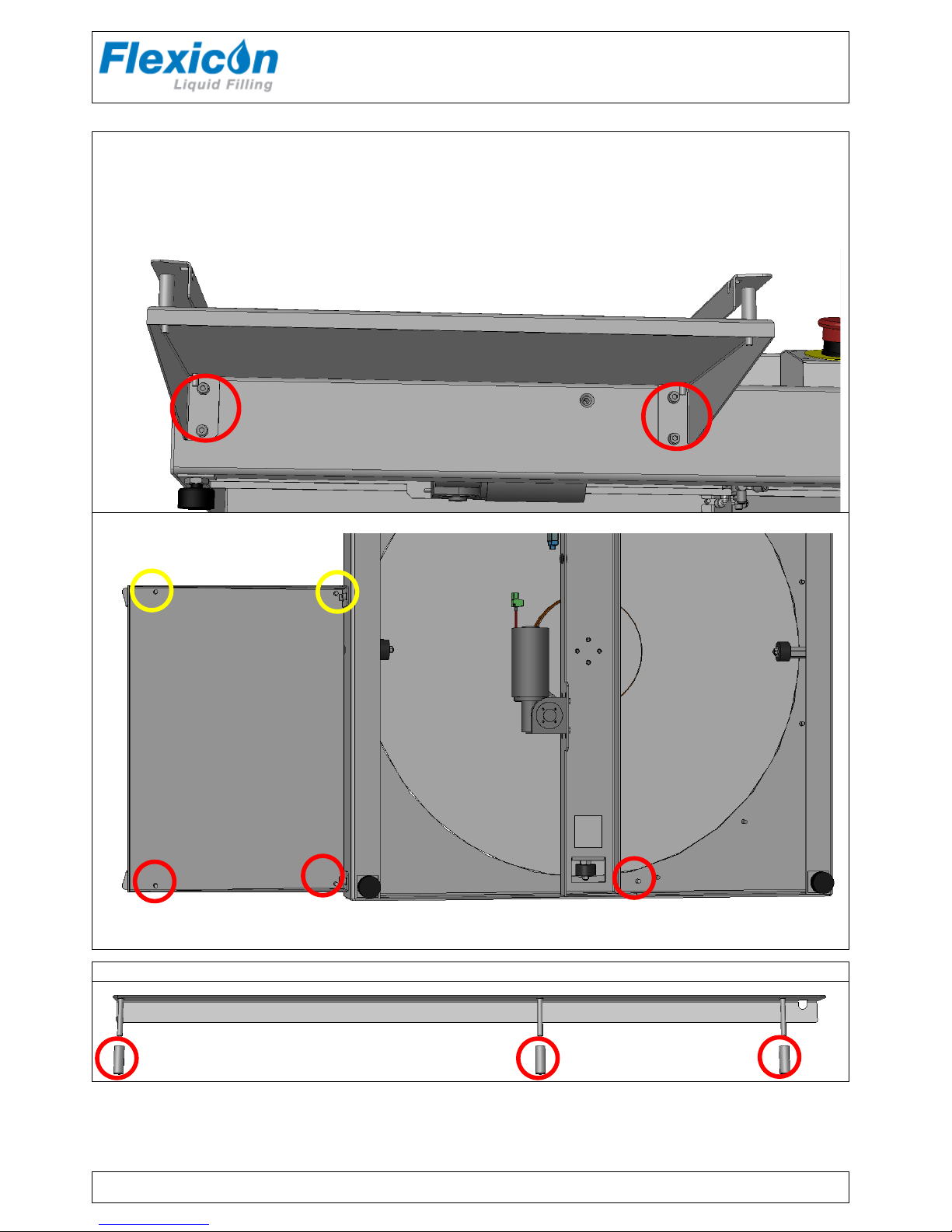
3.3.2.1 Mounting as side infeed tray
• Position tray as shown on page 5.
• Mount the screws as shown in the red circles and tighten them loosely.
• Adjust the the tray so it is flush with the top surface of the FF20.
• Tighten the screws.
3.3.2.2 Mounting the long railing for side infeed.
The FF20 comes with a short railing mounted on the infeed tray- yellow circles.
There are 2 long railings: 1 for side infeed and 1 for front infeed.
Railing for side infeed with spacers
• Position the railing with spacers in the aligning holes – red circles above.
• Add nuts and tighten loosely.
• Align the end of the long railing to the cirkular railing.
• Tighten the nuts.
Page 7
INSTRUCTION HANDBOOK
FF20
FF20 IH EN 74-215-051 v1.02.doc Version: 1.02 Page 7 of 21
3.3.2.3 Mounting as front infeed tray
• Position tray as shown on page 5.
• Mount the screws as shown in the red circles and tighten them loosely.
• Adjust the the tray so it is flush with the top surface of the FF20.
• Tighten the screws.
3.3.2.4 Mounting the long railing for side infeed.
The FF20 comes with a short railing mounted on the infeed tray- yellow circles.
There are 2 long railings: 1 for side infeed and 1 for front infeed.
Railing for front infeed with spacers
• Position the railing with spacers in the aligning holes – red circles.
• Add nuts and tighten loosely.
• Align the end of the long railing to the circular railing.
• Tighten the nuts.
Page 8

INSTRUCTION HANDBOOK
FF20
FF20 IH EN 74-215-051 v1.02.doc Version: 1.02 Page 8 of 21
3.3.2.5 Mounting Outlet tray
• Position tray as shown on page 5.
• Mount the screws as shown in the red circles and tighten them loosely.
• Adjust the the tray so it is flush with the top surface of the FF20.
• Tighten the screws.
3.4 Mounting of filling stand
If the filling stand has been removed during shipping it is mounted as shown on the picture.
Fasten the bolt underneath the
base plate.
The filling stand must be
stable and immovable
Mount the nozzle holder on the stand
Page 9

INSTRUCTION HANDBOOK
FF20
FF20 IH EN 74-215-051 v1.02.doc Version: 1.02 Page 9 of 21
3.5 Technical specifications
3.5.1 Dimensions with front infeed
Page 10

INSTRUCTION HANDBOOK
FF20
FF20 IH EN 74-215-051 v1.02.doc Version: 1.02 Page 10 of 21
3.5.2 Dimensions with side infeed
Page 11

INSTRUCTION HANDBOOK
FF20
FF20 IH EN 74-215-051 v1.02.doc Version: 1.02 Page 11 of 21
3.5.3 Services
All electrical systems are placed underneath the base plate.
3.5.3.1 Power supply:
3.5.3.2 Compressed air supply:
Note:
Only authorised personnel can gain access to the installations.
The main power cable must be removed completely from power supply before the installations are
touched.
3.5.4 Bottles and trays
Bottle sizes
Diameter From Ø12 mm to Ø78 mm.
Tray size inlet / outlet
Inlet Outlet
Length / width 307 mm / 366 mm 307 mm / 366 mm
Height of rail 30 mm 30 mm
3.5.5 Ingress protection
Ingress protection IP32
3.5.6 Weight
Weight: app. 40 kg
3.5.7 Materials of construction
AISI304 stainless steel
Anodised aluminium
3.5.8 Optional fillers and capping machines
FF20 must be connected to a peristaltic filler in order to perform indexing of bottles.
Optional WMF fillers when filling are:
- PF6 or PF22 Peristaltic filler
- MC12 with PD12 or PD22 peristaltic filler
- 520 Di peristaltic filler
Page 12

INSTRUCTION HANDBOOK
FF20
FF20 IH EN 74-215-051 v1.02.doc Version: 1.02 Page 12 of 21
4 Installation
4.1 Connections
FF20 must be placed on a stable and horizontal bedplate.
The mains cable (1) is connected
to a single-phase power supply
with earth.
The filler is connected to (2)
See section 3.5.8
A UP20 can be connected to (3).
Flexnet from the pump is
connected to (4).
Compressed air is connected to
(1) by use of the supplied quick
release clutch.
All exhaust air is collected and
exhausted through the exhaust
filter (2)
Page 13

INSTRUCTION HANDBOOK
FF20
FF20 IH EN 74-215-051 v1.02.doc Version: 1.02 Page 13 of 21
5 Control panel
Emergency
Switch
Stops the machine immediately and ventilates the compressed air.
Power Indicator; lights when power is on.
Sensor
Bottle sensor indicator.
Lights when a bottle is present in front of the sensor.
Manual mode /
Automatic mode
Manual mode = Each bottle is moved through the filling area manually.
See “Release”
Automatic mode = Each bottle is moved through the system automatically
Release
Is used together with manual mode, only
When release is pressed the ejector will move once and push the bottles one
step further in the bottle sluice.
Round-table
Speed
Potentiometer for setting the speed of the round table.
1 = slow 10 = fast
Filling Delay
Potentiometer for adjusting the delay between each filling
1 = minimum time (~ fast process of bottles),
10 = maximum time (~ slow process)
E.g. if filling volume is small a high delay value can be an advantage.
Ejector Speed
Regulates the speed of the ejector.
Faster: Turn counter clockwise
Slower: Turn clockwise.
If the speed is too high, narrow bottles may fall over in the sluice.
Page 14

INSTRUCTION HANDBOOK
FF20
FF20 IH EN 74-215-051 v1.02.doc Version: 1.02 Page 14 of 21
6 Daily Use
6.1 Starting-up and running
Installation section must be carried out before this chapter can be performed.
When the main switch is pressed, an initial procedure starts and secure that the machine is ready for
production. The POWER ON light will turn on when the machine is ready.
6.2 Adjustments
Before starting up and running, the machine must be set up to the correct bottle size.
6.2.1 Adjusting the round table inner bottle rail
Adjust the inner bottle rail by loosening the
bolts and move the rail in or out; depending on
bottle size. The bottles should be stopped by
the rail in such a way that only one bottle at a
time can pass the space between the inner and
outer rail.
6.2.2 Adjusting the bottle sluice
The sluice consists of two guides.
• An adjustable guide (2) which can be adjusted for bottle size.
• A safety guide (4) which can’t be adjusted but can be moved along the yellow arrow in order to
prevent fingers from being damaged.
• Loosen the fastening screw.
• Move the guide (2) in. (downwards in picture)
• Place a bottle in each end of the sluice (3).
• Move the (2) out until there is about 1mm of room on each side of the bottle.
• Fasten the Screw (1)
1 2 3
4
Page 15

INSTRUCTION HANDBOOK
FF20
FF20 IH EN 74-215-051 v1.02.doc Version: 1.02 Page 15 of 21
6.2.3 Adjusting the inlet sensor
• Place a bottle so it is resting in the corner of the sluice rail (1).
• Loosen the sensor screw (2) and move it to the right.
• Watch the sensor indicator (see 5 - Control panel) and move the sensor to the left.
• When the sensor light goes on – fasten the sensor screw (2).
• Move the bottle back (up in picture) and control that the sensor light does not go on before the
bottle is resting against the sluice railing (1).
• If the sensor goes on too early – move it a little to the right.
• If the senor does not go on – move it a little to the left.
6.2.4 Adjustment of the filling stand
Adjust the filling stand and the filling nozzle over the centre of the second bottle in the sluice.
The nozzle tip should only be a few millimetres above the bottle top to minimise spill and spray.
second bottle in outlet sluice
1
2
Page 16

INSTRUCTION HANDBOOK
FF20
FF20 IH EN 74-215-051 v1.02.doc Version: 1.02 Page 16 of 21
6.3 Production START and STOP
FF20 is ready for production start when:
• bottles are placed on the round table/inlet tray
• the sluice is set up to the exact bottle size
• inlet sensor is adjusted
• the filling stand and nozzle are adjusted
• the external filler is connected and ready
• the “filling delay” is set, if necessary*
• control panel is set on “automatic mode”
• and the FF20 Power signal is ON
Set the speed of the round table; this will make the table move.
When a bottle is detected in the corner of the inlet sluice the bottle pusher will move it one step and filling
will begin.
*The time/pause between 2 fillings can be adjusted on the “filling delay”.
If filling volume is small a high “filling delay” value can be an advantage
Stopping during production can be done by turning the round table speed button to 0 or by changing to
manual mode.
6.4 Stepping bottles
First manual mode has to be selected.
Pressing the release button will perform one push of the bottle pusher causing all bottles in the outlet
sluice to move one bottle size forward, without filling.
Release is only available if the manual mode is selected.
6.5 Removing bottles from outlet / collection tray
When the outlet tray is full the operator can choose to stop the machine and empty the tray or to empty
the tray when production is ongoing and the tray is not packed.
Page 17

INSTRUCTION HANDBOOK
FF20
FF20 IH EN 74-215-051 v1.02.doc Version: 1.02 Page 17 of 21
7 Malfunctioning
7.1 Function errors / Trouble shooting
FF20 is a relatively simple machine to operate and normally errors will be due to incorrect adjustment of
certain functions.
In the table below, the most common faults are described and what causes it.
Description of fault
Possible cause
The bottles tip over when pushed into the
round table
- The inlet tray must be adjusted
See section 3.3
- The bottle disc must be adjusted
See section 9.1.2
The bottles do not enter the inlet of the
sluice, and stay on the round table
- The inner bottle rail must be adjusted
See section 6.2.1
The filling is not performed directly into the
present bottle
- Adjust the filling stand
See section 6.2.4
- Adjust the sluice
See section 6.2.2
Filling is not performed at all
- Control that the cable is connected.
- Consult the manual of the filler
- “Disp.” hasn’t been pressed on filler controller before
pressing “START” on FF20.
Press “DISP.” On filler controller.
AND If a bottle is ready under the filling station press
then press “GO” on the filler controller.
More than 1 filling is performed in the
same bottle.
- F6 (Batch Size) has been set to more than 1 on filler
controller.
Set F6 to 1.
The bottles tip over in the outlet
- Adjust the sluice railing
See section 6.2.2
- Adjust the speed of the ejector
See section 5
The ejector does not push the bottle
through the sluice
- Control that compressed air is connected
- Adjust the inlet sensor
See section 6.2.3
- Machine is in “manual mode”
See section 5
The bottles tip over when pushed into the
outlet tray
- The outlet tray must be adjusted
See section 3.3
The round table does not run steady
- The toothed belt needs tension
See section 9.1.1
Ejector speed doesn’t change when the
regulator is turned.
- The knob has been turned too far to the left.
Lift the knob off.
Press the regulator down and screw it back onto its
threading (clockwise).
Set the speed to the lowest desired speed and press the
knob back on.
Page 18

INSTRUCTION HANDBOOK
FF20
FF20 IH EN 74-215-051 v1.02.doc Version: 1.02 Page 18 of 21
8 Cleaning
8.1 Cleaning Frequency
As FF20 is not in direct contact with the dispensed product, daily cleaning might not be necessary.
Cleaning might be determined by local SOP’s and cleaning validations; but must never be with
detergents more potent than the ones below.
8.2 Preparations for cleaning
Before cleaning the machine:
Turn off the power
Remove the filling nozzle and the filling tubes
8.3 Cleaning Guidance
Correct cleaning of the FF20 is carried out by washing it off with water or detergents, using a lint-free
firmly wrung cloth or lint-free paper towel; subsequently the machine is wiped off with a dry cloth.
8.4 Detergents or cleaning agents
Normal cleaning agents such as tepid/medium hot water, ethyl alcohol (ethanol) 70% and may be used
all over the machine.
The FF20 consists of stainless steel and anodized aluminium, and can be cleaned in several ways:
Cleaning of parts
made of:
Can be
autoclaved
Can be cleaned with ethyl
alcohol 70%
Can be cleaned with
water and afterwards
wiped off with dry a cloth
Stainless steel X X
X
Anodized aluminium X X
X
Plastic parts X
X
Nylon
(Compressed Air tubes)
X
Optical sensors* X
X*
*Optical Sensors can be cleaned with alcohol, but over time this can cause a milky surface
Either avoid cleaning the sensor optics with solvents or be sure to wipe them immediately afterwards with a soft dry
cloth.
Recommendation: Keep a log on the cleaning.
Page 19

INSTRUCTION HANDBOOK
FF20
FF20 IH EN 74-215-051 v1.02.doc Version: 1.02 Page 19 of 21
9 Maintenance & service
9.1 Maintenance
9.1.1 Tension of toothed belt
If the toothed belt is slipping it needs to be tightened.
Turn of power, remove all connections to other equipment and tip
the FF20 to gain access to the toothed belt.
Loosen the 4 bolts
underneath and move the
motor to the left until the belt
is tense again.*
*Note - The toothed belt must not be stretched by use of tools while tensioning is being performed.
9.1.2 Alignment of bottle disc (round table)
If the bottle disc has become out of alignment with the inlet tray and the bottle sluice, the bottles will not
glide easily.
The bottle disc can be aligned from underneath the FF20 via the 4 conically shaped plastic rollers.
Turn of power, remove all connections to other equipment and tip the FF20 to gain access to the
plastic rollers.
Loosen the small bolt on the outside of the FF20 and adjust on the hexagon pole inside.
Do not loosen the bolt on top of the roller.
When the bottle disc is aligned all the loosened bolts must be tightened again.
Page 20

INSTRUCTION HANDBOOK
FF20
FF20 IH EN 74-215-051 v1.02.doc Version: 1.02 Page 20 of 21
9.1.3 Alignment of trays
If the inlet tray or the outlet tray have become out of alignment the bottles will not glide easily.
The trays can be aligned as described in the installation section, see section 3.3.2.1, 3.3.2.3 or 3.3.2.5.
9.2 Service
Should service be needed, please contact W-M Flexicon or your local supplier.
9.3 Methods and frequency of inspections for safety functions
Safety functions should be tested once a year:
Emergency switch
When pressed the entire machine and the peripherals connected through the 2 power outlets are
turned completely off. Compressed air is switched off and released.
Ejector Safety Beam
The ejector safety beam can be pushed back without use of force.
Keep a log and read the previous log recordings to present an overview of the machines state.
After testing the safety functions the results must be recorded in the log.
10 Change of voltage
FF20 can be converted to accept another supply voltage.
The conversion is carried out inside the control box by moving the cables of the transformer clamps, to
the position indicated in the picture below.
Change of voltage
Page 21

INSTRUCTION HANDBOOK
FF20
FF20 IH EN 74-215-051 v1.02.doc Version: 1.02 Page 21 of 21
11 Declaration of conformity
We WM-Flexicon A/S
Frejasvej 2-6
DK-4100 Ringsted
Declare on our sole responsibility that the product:
Bottle handling system Item no.
FF20 92-170-000
To which this declaration relates is in conformity with the following standard(s):
DS EN/ISO 12100
Safety of machinery - Basic concepts, general
principles of design
DS/EN 60204
Safety of machinery – Electrical equipment of
machines
According to the provisions in the Directives:
2006/42/EC
On the approximation of the laws of the Member
States relating to machinery
2006/95/EC
On the harmonization of the laws of Member
States relating to electrical equipment designed
for use within certain voltage limits
2004/108/EC
On the approximation of the laws of the Member
States relating to electromagnetic compatibility
July 2016
Ringsted, Denmark
Signature:
Jørn Jeppesen, Development Manager
 Loading...