

Page 1
RGB+W M8 Remote Control & Receiver
User Guide
COLOR CHANGING + WHITE M8
LED Remote Control & Receiver
INTRODUCTION
The M8 remote control and receiver for RGBW LED strip lights uses the most advanced RF wireless transmission technology. The system consists
of 2 parts: the handheld remote control and the in-line receiver.
Featuring a fully programmable remote control which allows you to quickly choose red, green, blue or white, cycle through 6 preset colors, 6 preset
modes, create and save color schemes and alter the brightness of your strips. In addition, it includes a wall mount to easily place the remote control
on a nearby wall.
This unit is compatible with any of the Flexfire LEDs RGB+W LED strip light.
SAFETY AND WARNINGS
Install in accordance with the National Electric Code, and local regulations.
•
This product should be installed and serviced by a qualified electrician.
•
Do not connect directly to high voltage 120V AC power.
•
This product is rated for indoor installation and is not protected against moisture.
•
Proper heat dissipation will prolong the working lifespan of this product. Install in a well ventilated area.
•
Only install compatible LED drivers and fixtures. Contact Technical Support or visit the product page for compatible accessories.
•
Ensure applicable wire is installed between driver, fixture, and any controls in between. When choosing wire, factor in voltage drop, amperage
•
rating, and type (in-wall rated, wet location rated, etc). Inadequate wire installation could overheat wires and cause fire.
Utilize the wiring diagrams in this installation guide for basic setups.
•
JUMP3
JUMP7
5
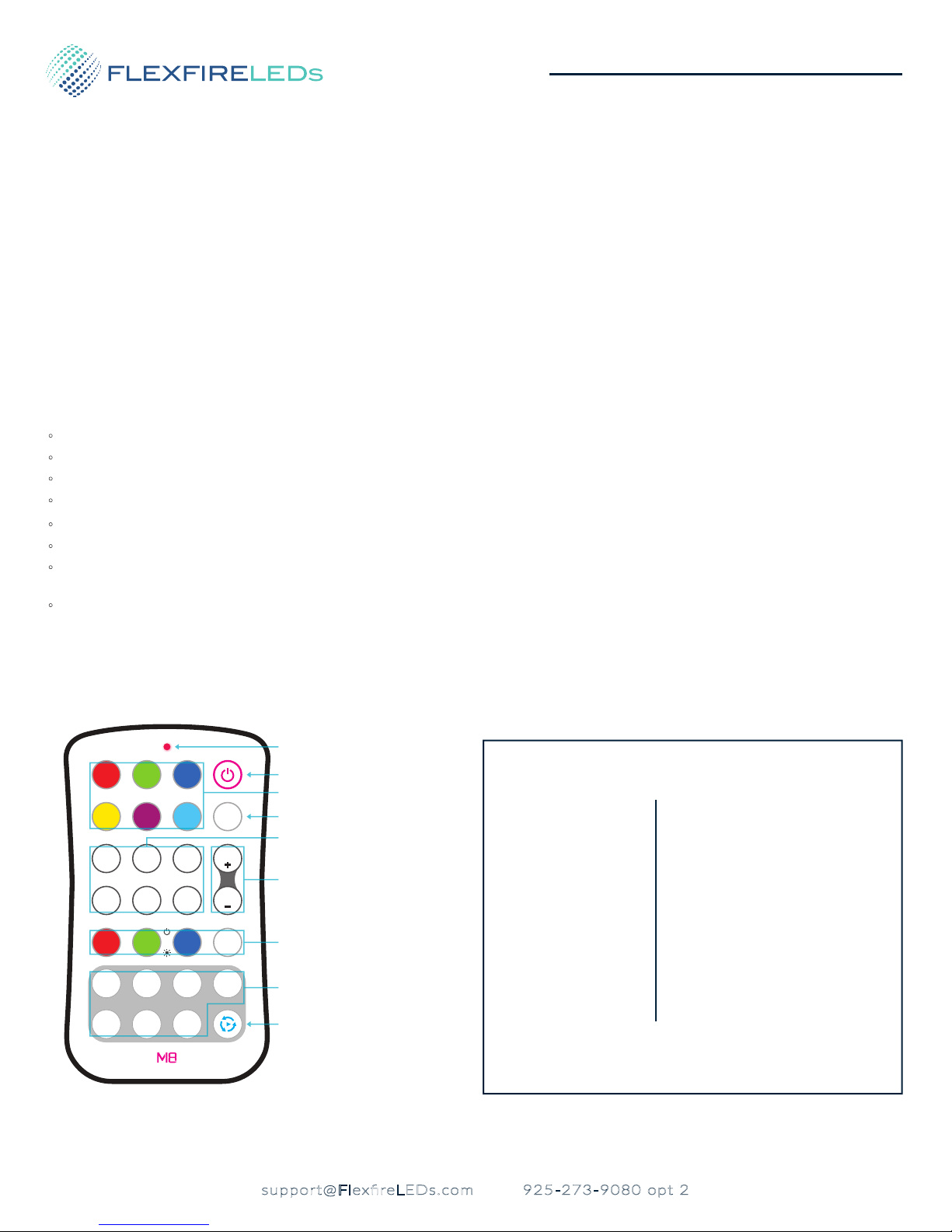
REMOTE CONTROL
Signal Indicator LED
BLUEGREENRED
PURPLEYELLOW
AUTOCYAN
B/S
FLASHFADE3
FLASH7FADE7
B/S
WBGR
I
2
I
I
6
I
I
RF WIRELESS
4
3
I
I
7
I
I
On/Off Button
Color Shortcuts
6 Mode Auto Play
Mode Shortcuts
Brightness/Speed
(color/mode shortcuts)
Custom Color Commands
(press and hold each color to dim)
Custom Color Save
Switch and Play
(switch or play saved colors 1-7)
Details
SKU:
Working Voltage:
Working Frequency:
Max. Signal Range:
Working Temp:
Dimensions:
Weight:
Warranty:
*Replace with CR2032 battery (Standard watch battery
from local hardware store)
**Comes with a wall mount for easy storage
RGBW-CTRL-M8
3V (CR2032 battery)*
433.92MHz
130ft (40m)
-4°F ~ 131°F (-20°C ~ 55°C)
H: 4 1/4” (104mm) W: 2 5/16” (59mm)
D: 3/8” (9mm)**
1.48oz (42g)
5 years
RGBW-CTRL-M8
support@FlexfireLEDs.com 925-273-9080 opt 2
1page
V.2018.11.01
Page 2
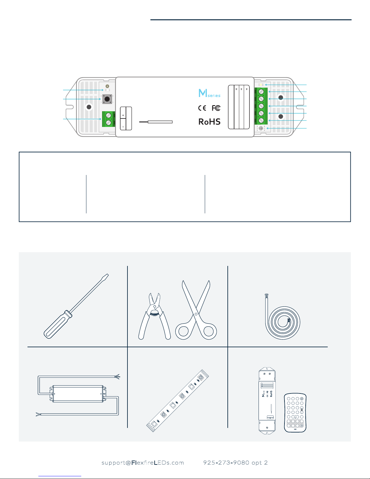
Power Indicator LED
Sync Button
Power Input Terminal
Details
SETTING
ADRESS
LED CONTROLLER
RF WIRELESS REMOTE CONTROL
MODEL: M4-5A
POWER INPUT: DC5V-DC24V
DC DC
OUTPUT: 5Ax4CH MAX:20A
POWER
8mm wire preparation
1-2.5º / 17-13 AWG
RECEIVER
V
W
OUTPUT
W
W
V
WW
NC
WW
NW
User Guide • RGB+W M8
White Indicator LED
V
WG
B
R
Positive Channel
White Channel (Negative)
Blue Channel (Negative)
Green Channel (Negative)
Red Channel (Negative)
RGB Color Indicator LED
SKU:
Input Voltage:
Max Current Load:
Max Output Power:
YOU’LL NEED
Small flat-head screwdriver (4mm) Wire strippers or scissors 5-wire stranded low voltage wire for
RGBW-CTRL-M8
5V-24V DC
5A x 4CH
12V: 240W, 24V: 480W
Working Temp:
Dimensions:
Weight:
Warranty:
-22°F ~ 131°F (-30°C ~ 55°C)
H: 6 15/16” (176mm) W: 1 3/4“ (45mm) D: 1 3/16” (30mm)
4.23oz (120g)
5 years
extended runs (consult an electrician for
wire gauge advice)
Low voltage non-dimmable
power supply
DCAC
support@FlexfireLEDs.com 925-273-9080 opt 2
RGBW-CTRL-M8
ColorBright™ RGBW LED strip Remote control & receiver
V
R
WG
V
NCBWW
WNWV
WWWW
OUTPUT
BLUEGREENRED
CYAN
PURPLE
AUTO
YELLOW
B/S
JUMP3
LED CONTROLLER
RF WIRELESS REMOTE CONTROL
MODEL: M4-5A
POWER INPUT: DC5V-DC24V
ADRESS
SETTING
DC DC
OUTPUT: 5Ax4CH MAX:20A
8mm wire preparation
POWER
1-2.5º / 17-13 AWG
FLASHFADE3
B/S
JUMP7
FLASH7FADE7
WBGR
I
3
2
I
I4I
I
5
7
6
I
I
I
RF WIRELESS
2page
V.2018.11.01
Page 3
User Guide • RGB+W M8
INSTALLATION
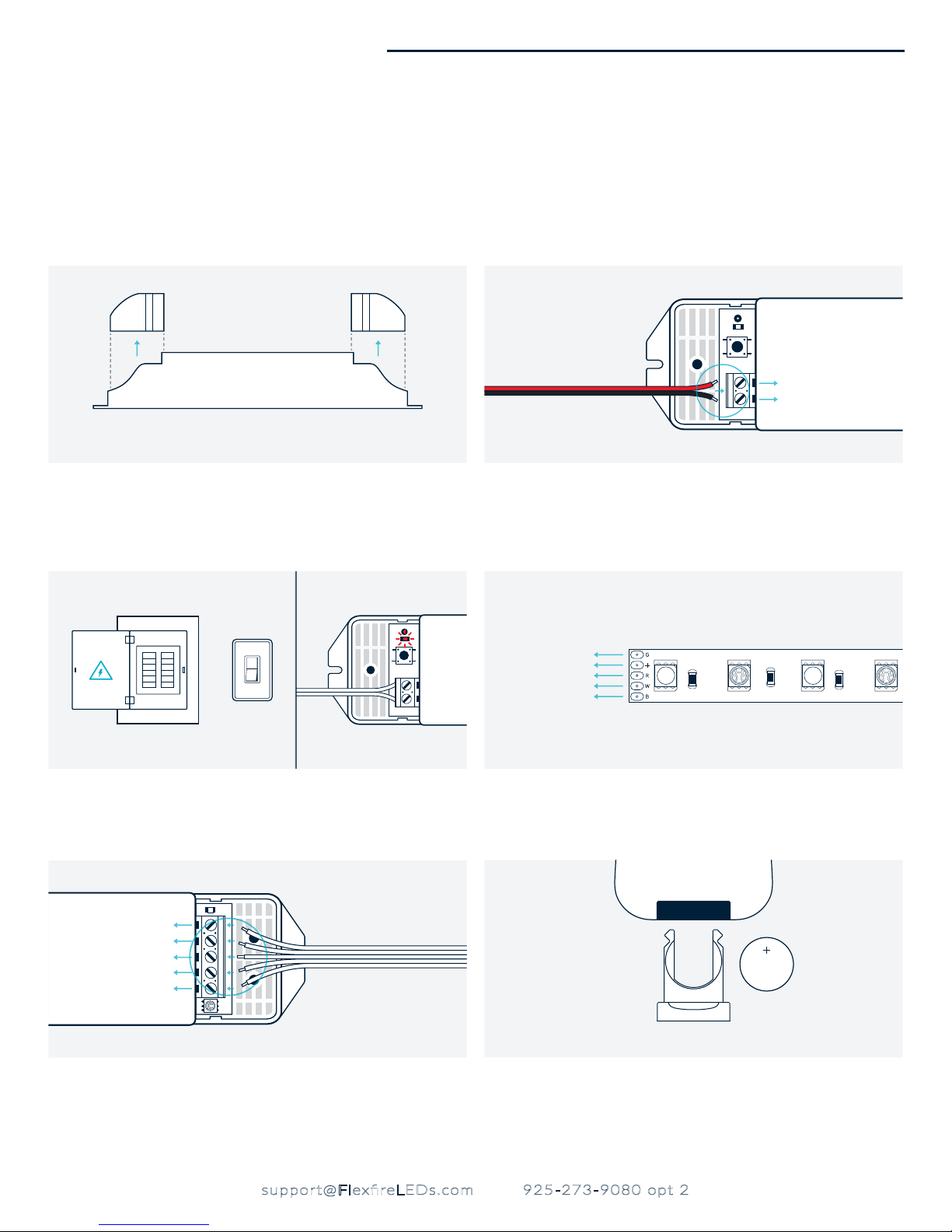
Always pre-test your LED setup prior to permanent installation. This will ensure all components work correctly. Be sure to check the amperage
rating of the LED strip you’ve purchased so the receiver isn’t overloaded (max 5 amps per channel). Turn off the main AC breaker for the line you’ll
be using before installing your low voltage power supply. If you experience any issues at all with your test set up, please be sure to contact us at
After Sales Support.
1. 2.
Positive (DC+)
Negative (DC-)
Unscrew the left and right cover plates on the receiver. This will expose
the Input and Output Power Terminals.
3. 4.
or
Turn the main breaker for the AC line back on to power your non-dimmable power supply. The red Power Indicator LED on the receiver will
start flashing slowly demonstrating that it’s getting power.
5. 6.
V+
W
B
G
R
Loosen the Power DC+ and DC- screws and insert the black wire from
your low voltage non-dimmable power supply in the DC- channel and
secure the screw. Then insert the red wire from the power supply in the
DC+ channel and secure the screw.
Green
Positive (+)
Red
White
Blue
ColorBright™ RGBW
Look at your LED strip carefully and identify the positive (+), R, G, B and
W channels.
CR2032
3V
Loosen the Output V+, R, G, B, and W screws. Then connect the + wire
from the LED strip to the V+ channel in the receiver and secure the
screw. Do the same to match the rest of the letters to their respective
channels.
support@FlexfireLEDs.com 925-273-9080 opt 2
RGBW-CTRL-M8
Open the tray on the back of the remote and make sure the battery
doesn’t have the protective plastic.
3page
V.2018.11.01
Page 4
B/S
AUTOCYAN
YELLOW
FLASHFADE3
JUMP3
BLUE
PURPLE
GREENRED
BLUEGREEN
RED
B/S
B/S
AUTO
CYAN
PURPLE
YELLOW
FLASHFADE3
JUMP3
FLASH7FADE7
JUMP7
BLUEGREEN
RED
I
7. 8.
B/S
AUTO
FLASH
CYAN
BLUE
FADE3
PURPLE
GREEN
YELLOW
RED
4
WBGR
B/S
FLASH7
FADE7
JUMP7
JUMP3
I
7
I
3
RF WIRELESS
I
6
I
2
I
5
I
I
*Long Beep*
User Guide • RGB+W M8
BLUEGREENRED
2
I
6
I
RF WIRELESS
AUTOCYANPURPLE
B/S
FLASHFADE3
B/S
FLASH7FADE7
WBGR
3
I4I
7
I
YELLOW
JUMP3
JUMP7
I
I
5
I
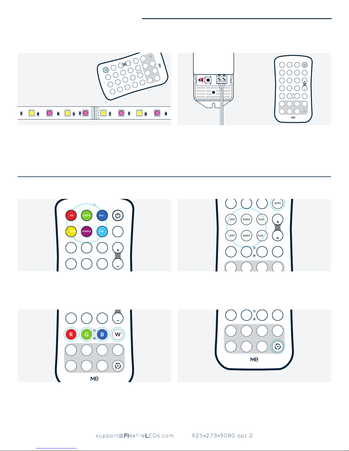
Press the Power Button on the remote control, the LED strip will turn on.
Press the black Sync Button on the receiver once and the the Power
Indicator LED will remain static, then quickly press any button on the
remote and the Power Indicator LED will flash faster then continue
flashing at a slower pace as before. The remote is synced. (To reset the
receiver and try again, press and hold the sync button until it beeps
twice (about 10 seconds). The receiver is reset)
ADDITIONAL FEATURES
BLUE
GREENRED
YELLOW
JUMP3
JUMP7
PURPLE
AUTOCYAN
FLASHFADE3
FLASH7FADE7
B/S
B/S
Preset Colors Preset Modes
There are 6 preset colors on the remote, Red, Green, Blue, Yellow, Purple
and Cyan. Use the B/S+ or B/S- to control the brightness for these preset
colors.
There are 6 preset modes on the remote, Jump3, Fade3, Flash, Jump7, Fade7 and
Flash7. Use the B/S+ or B/S- to control the speed for these preset modes . Use the
AUTO button to scroll through all the preset modes.
YELLOW
JUMP3
JUMP7
I
I
PURPLE
2
I
FLASH7FADE7
CYAN
FLASHFADE3
AUTO
B/S
B/S
WBGR
4
3
I
I
JUMP7
FLASH7FADE7
I
I
5
I
2
I
6
I
B/S
WBGR
4
3
I
I
7
I
Create A Custom Color
The R, G, B and W buttons are used to adjust the brightness on the red, green,
blue and white channels independently. Simply press and hold each relative
button to create any color and brightness desired. Then save by pressing and
holding the number (1-7) you’d like to save the color to for 2 seconds. In the
future simply quick press the number it was saved to access the color you
created.
RGBW-CTRL-M8
support@FlexfireLEDs.com 925-273-9080 opt 2
WBGR
I
2
I
I
5
6
I
I
RF WIRELESS
4
3
I
I
7
I
Scroll Through Your Custom Colors
Use the Switch and Play button to scroll through your custom colors saved in 1-7
by pressing and selecting the mode you wish the colors to go through (Jump,
Fade or Flash).
V.2018.11.01
4page
Page 5
DC
AC
RF
DC
AC
RF
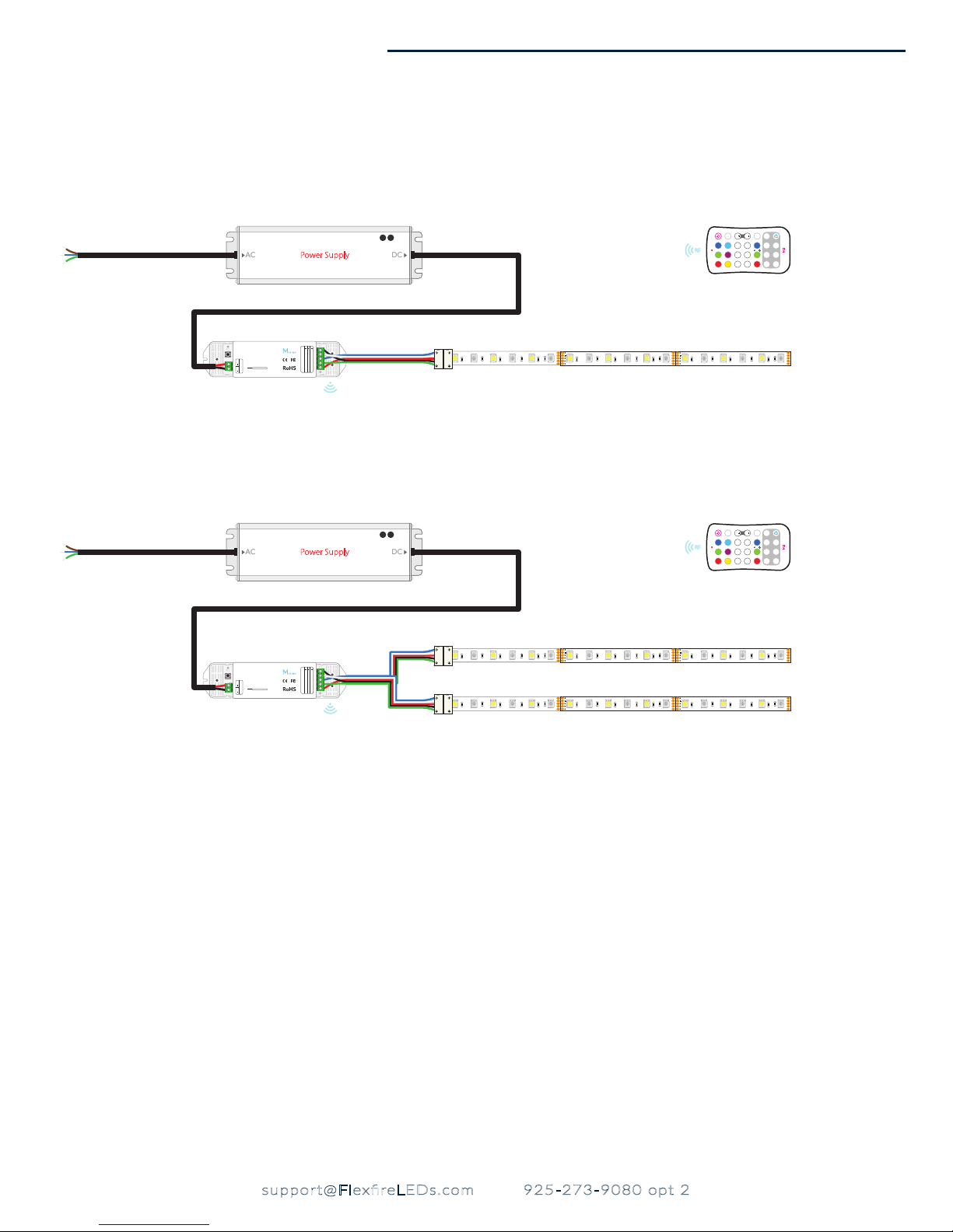
WIRING DIAGRAM
1. In Series Wiring
2. Parallel Wiring
SETTING
ADRESS
DC DC
POWER
LED CONTROLLER
RF WIRELESS REMOTE CONTROL
MODEL: M4-5A
POWER INPUT: DC5V-DC24V
OUTPUT: 5Ax4CH MAX:20A
8mm wire preparation
1-2.5º / 17-13 AWG
Power Supply
V
V
V
WG
WW
B
W
NC
OUTPUT
W
WW
R
W
NW
LED Area 1
User Guide • RGB+W M8
I
I
4
B/S
B/S
WBGR
AUTO
I3I
BLUE
CYANPURPLEYELLOW
GREEN
RED
7
FLASHFADE3JUMP3
FLASH7FADE7
I2I
RF WIRELESS
6
III
5
JUMP7
SETTING
ADRESS
DC DC
POWER
LED CONTROLLER
RF WIRELESS REMOTE CONTROL
MODEL: M4-5A
POWER INPUT: DC5V-DC24V
OUTPUT: 5Ax4CH MAX:20A
8mm wire preparation
1-2.5º / 17-13 AWG
Power Supply
V
V
V
WG
WW
B
W
NC
OUTPUT
W
WW
R
W
NW
LED Area 1
I
I
4
B/S
B/S
WBGR
AUTO
I3I
BLUE
CYANPURPLEYELLOW
GREEN
RED
7
FLASHFADE3JUMP3
FLASH7FADE7
I2I
RF WIRELESS
6
III
5
JUMP7
RGBW-CTRL-M8
support@FlexfireLEDs.com 925-273-9080 opt 2
5page
V.2018.11.01
Page 6

User Guide • RGB+W M8
TROUBLESHOOTINGTROUBLESHOOTING
- If your lights are not turning on or ickering:
• Check that the red Power Indicator LED on the Power Input side of the receiver is flashing. If it’s not flashing the receiver isn’t getting power,
make sure the polarity of the power supply wires match the polarity of the channels on the Power Input Terminal.
• If the red Power Indicator LED on the Power Input side is flashing normally, check the polarity on the Power Output side. Make sure you have
matched the markings on the LED strip to the channels on the receiver.
• Make sure all the connections (solderless connectors, solder joints, terminal blocks, wire-nuts and spliced wires) are secure and making correct
contact.
• Check that you have a compatible power supply, low voltage non-dimmable power supply that is big enough to handle the load of the LED
strips you are using.
If you are missing color temperatures or they don’t match:
-
• Check the connections on the Power Output (LED side) of the receiver, the brown, yellow and white wires need to match the letters on each of
the channels V+, B, G, R and W. Make sure the wires are properly stripped and contact in the screw terminals is done on the metal wire and not
on the plastic insulation.
• If you have soldered the connection, make sure none of the solder points are touching each other, this will make the the channels that are
touching work simultaneously.
• If you are using solderless connectors, apply preasure on the connector. If the issue is resolved with preassure change that connector. It could
be faulty.
• Make sure you follow the letters indicating polarity on the LED strip throughout your setup when cutting the strip to avoid changing the color
temperature from one section to another.
If you can’t sync the receiver with the remote:
-
• Revise the previous sync instructions to sync, assign zones and reset the receiver or remote.
WARRANTY
Limited Warranty on Purchased Items:
All products sold by Flexfire LEDs and shipped within the 50 United States, Canada, and Mexico come with a limited warranty. This limited warranty
does not include product failures that are the result of:
1. Not using a voltage regulated driver to connect the LED product or controls;
2. Connecting LED products to the wrong Output Voltage;
3. Improper connection of drivers, LED products, or controls;
4. Connecting LED products or controls directly to any AC power source;
5. Connecting drivers backwards to an AC power source;
6. Using products in an extremely hot or cold environment and/or without adequate ventilation as overheating will cause the LEDs and transform-
ers to fail more quickly;
7. Water damage to products not specifically sold as waterproof products;
8. Electrical power surges;
9. Damage from hail, flooding, tornado, fire, wind, earthquake, lightning, electrical storm, or any other natural disaster;
10. Damage caused by a vehicle or other accident;
11. Damage caused when transporting the item;
12. Damage to any products that were modified by the user, used for purposes other than as intended or directed, or connected to LED systems
or components not purchased from Flexfire LEDs.
This limited warranty also expressly excludes coverage for excessive wear and tear and/or physical or accidental abuse, loss, or theft. Improper repair
or warranty service performed by someone other than Flexfire LEDs will void this warranty. Buyer is responsible for the safe transport of any item
sent to Flexfire LEDs for warranty service.
If you have an item you believe to be faulty, contact Flexfire LEDs immediately and request tech support. You may be required to provide photos,
videos, and/or descriptions of the item(s) not performing properly. It is Flexfire LEDs goal to troubleshoot thoroughly to eliminate any unnecessary
time or hassle on behalf of the customer. Failure to comply and provide the information requested by Flexfire LEDs will result in a void of warranty.
If a product is deemed faulty by a technician/representative, then a return shipping label and a Return Merchandise Authorization (RMA) form will
be sent out immediately. Once Flexfire LEDs receives the product, we will test the item(s) to better understand where the fault in the product lie(s).
RGBW-CTRL-M8
support@FlexfireLEDs.com 925-273-9080 opt 2
6page
V.2018.11.01
Page 7

User Guide • RGB+W M8
Flexfire LEDs will NOT provide replacement items before the original items have been returned, tested, and deemed faulty. If you need a replacement item while the return process is taking place, then you can repurchase that item. Once the testing process is complete and assuming the
product is faulty, a refund will be issued for the purchase price of the product. Flexfire LEDs will not refund shipping costs on replacement items
If the product is found to be working properly and the error lies in the installation, or with other non-Flexre LEDs products being used, then the
product will be returned to the customer via our standard shipping method paid by the customer. If the customer has paid for a replacement item
while the return process is being processed and the original product is found to be working properly, then the customer will receive the original
product back and no refund.
Buyer’s sole right under this warranty is for repair or replacement of the defective item.
This warranty is not transferable and applies only to the original purchaser of such items, provided that products purchased from an authorized
Flexfire LEDs reseller will also include the above limited warranty. Proof of purchase may be required.
Warranty Period:
In the event of a product defect or malfunction, Flexfire LEDs will cover the cost of the return shipping. This is only valid during the product’s
warranty period stated by Flexfire LEDs. In this case a prepaid shipping label will be issued to the client via our standard shipping method.
• If the item is faulty, Flexfire LEDs will ship out a replacement at no charge.
• If the item is not faulty (still works), the client will need to pay for the shipping to get the product back to them.
RGBW-CTRL-M8
support@FlexfireLEDs.com 925-273-9080 opt 2
7page
V.2018.11.01
 Loading...