

Page 1
FlexDSL Telecommunications AG
Steinackerstrassse 31
8902 Urdorf
Switzerland
Page 1/9
Tel: +41 44 741 52 90
Fax: +41 44 741 52 93
Email: info@flexdsl.ch
Web: www.flexdsl.ch
Ddd
The FlexDSL Orion3 product family offers a broad range of products, which are based on the latest SHDSL.bis standards
(ITU-T G.991.2 & ETS TS 101 524) The FlexDSL Orion3 supports TC-PAM16/32 and the new TC-PAM4/8/64/128 line coding.
The FlexDSL Orion3 allows symmetrical data and voice transmission at speeds up to 15.2Mbps over a single pair of copper.
In addition, the FlexDSL Orion3 supports DSL channel bonding for up to 4 copper pairs in order to achieve speeds to
60.8Mbps. The SFP module (available on selected models) allows Ethernet data transmission over mixed Copper and Fiber
media.
FlexDSL Orion3 SHDSL.bis Extended modems can provide up to 2 E1 interfaces, which support framed and unframed
services (G.703/G.704). An integrated 2 or 4 port Ethernet layer 2 managed Switch with VLAN support (10/100BaseT)
ensures connectivity to IP services. Beside of E1 and Ethernet the additional Nx64 interfaces can be configured as V.35, V.36,
X.21, V.28, or RS232/RS485 interface (cable selectable).
Like all FlexDSL Orion products, the Orion3 SHDSL.bis modems family is based on industrial components, have extended
temperature range, advanced surge protection and produced in Switzerland.
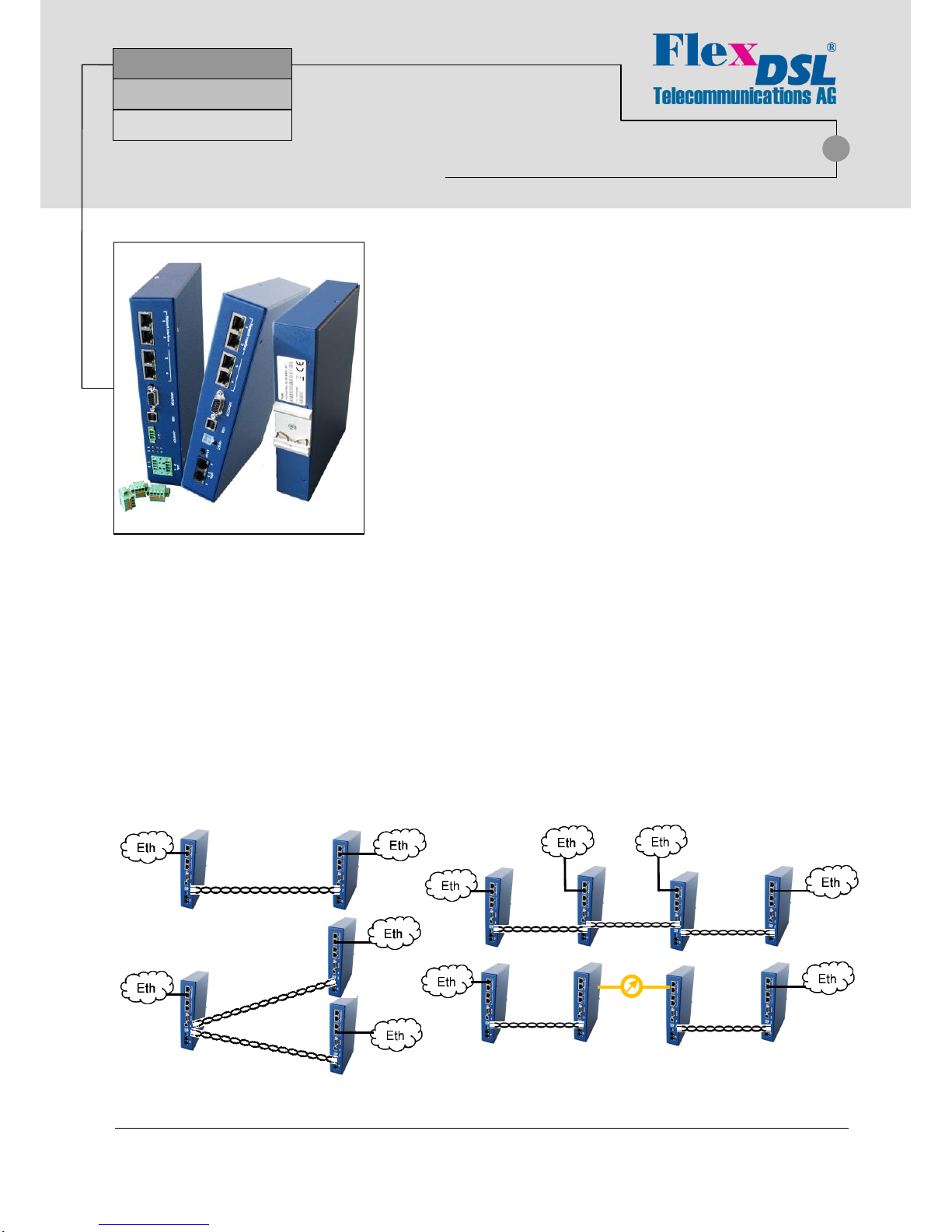
Possible Applications
SHDSL.bis
Up to 60Mbps
E1 / Nx64 /Ethernet
FlexDSL Orion3
Features
• Up to 15Mbps Data Transmission per Copper Pair
• SHDSL and SHDSL.bis, TC-PAM16/32
• Additional TC-PAM4/8/64/128 Available
• 1, 2 or 4 Copper Pairs Support
• 2 or 4 Port Ethernet Switch (10/100BaseT)
• SFP connector for mixed Copper and Fiber applications
• QoS, VLAN and RSTP Support
• E1 (G.703/704, Balanced/Unbalanced)
• Nx64 (V.35, V.36, X.21, V.28) and RS-232/485
• Multi-Service Operation
• Point-to-Point and Point-to-Multipoint Operation
• Console Port, Telnet, Web, SNMP Management
• 24/48VDC Powered, Low Power Consumption
• Included Primary Protection
• Robust DIN-Rail Metal Enclosure
d)
a) Ethernet Transmission Point-to-Point
b) Ethernet Transmission Point-to-Multipoint
c) Ethernet Add/Drop over a Long Copper Line
d) Ethernet Transmission over Copper and Fiber
a)
b)
c)
Page 2
FlexDSL Telecommunications AG
Steinackerstrassse 31
8902 Urdorf
Switzerland
Page 2/9
Tel: +41 44 741 52 90
Fax: +41 44 741 52 93
Email: info@flexdsl.ch
Web: www.flexdsl.ch
Quick Installation Guide
Enter an Orion3 Device
You can use the Monitor (Local Craft Terminal, RS-232) interface with Hyper Terminal (or any equal program) or you can
address the device with Telnet through the Ethernet interface.
Monitor (LCT, RS-232 or USB) Interface:
Configure the COM port: Bits per second:9600, Data bits: 8, Parity: None, Stop bits: 1, Flow control: None
Press <ENTER>.
Telnet through Ethernet Interface:
Type in command line <Telnet 192.168.0.235> and press <ENTER>. This is the default Ethernet Address for Orion3
devices.
After a successful entering the main menu of the device will be displayed.
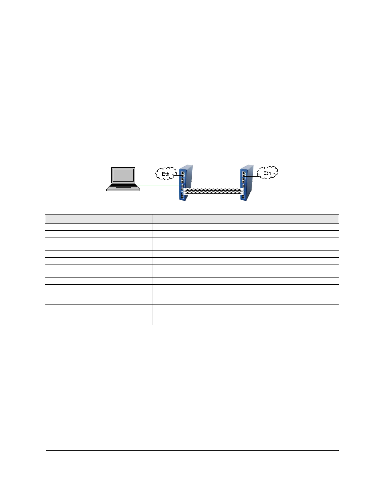
Configure an Orion3 Device
A first installation example with the most important commands and points to care about is shown below. We just like to have
an Ethernet transmission between the two devices over 2 SHDSL copper pairs with a speed of 11.4Mbit/s. The pairs should
aggregate (bundle) the data traffic and in case of any SHDSL pair failure, the remaining pairs should continue to work.
Enter in device 1 with the Monitor (LCT, RS-232 or USB) or Telnet interface.
Type following commands
Description
3 <>
Go to Configuration Management (CM)
<DEFAULT EVERYTHING> <>
Set everything to default configuration
<MASTER ON 1> <>
Configure SHDSL 1 as MASTER
<MASTER ON 2> <>
Configure SHDSL 2 as MASTER
<PAYLOAD WAN 1> <>
Configure Ethernet over SHDSL 1
<PAYLOAD WAN 2> <>
Configure Ethernet over SHDSL 2
<NET> <>
Go to NET menu
<SETIP 10.0.2.200> <>
Set the IP-address of the device
<NETMASK 255.0.0.0> <>
Set the subnet mask
<GATEWAY 10.0.0.101> <>
Set the default gateway
<M> <>
Go to Configuration Management (CM)
<M> <>
Go to Main Menu
2 <>
Go to Fault and maintenance management (FMM)
<APPLY ALL> <>
Apply all configurations (written in the running config.)
<CONFIRM> <>
Confirm all configurations (written in the startup config.)
In Menu Configuration Management (CM) you can type <CONFIG> to see the following picture:
CO_CM>CONFIG
--------------------------------------------------------------------------------
Running Line Configuration
--------------------------------------------------------------------------------
xDSL DSL1 DSL2
Mode : Master(HTU-C) Master(HTU-C)
Extended rates: OFF OFF
Line coding : PAM32 PAM32
Baserate : 89 89
Annex : B B
Payload : WAN WAN
Clock source : Int Int
GS compatible : OFF
NM threshold : OFF
LA threshold : OFF
--------------------------------------------------------------------------------
CO_CM>
Device 1
Device 2
Computer
Page 3
FlexDSL Telecommunications AG
Steinackerstrassse 31
8902 Urdorf
Switzerland
Page 3/9
Tel: +41 44 741 52 90
Fax: +41 44 741 52 93
Email: info@flexdsl.ch
Web: www.flexdsl.ch
Enter in device 2 with the Monitor (LCT, RS-232 or USB) or Telnet interface.
Type following commands
Description
3 <>
Go to Configuration Management (CM)
<DEFAULT EVERYTHING> <>
Set everything to default configuration
<MASTER OFF 1> <>
Configure SHDSL 1 as SLAVE
<MASTER OFF 2> <>
Configure SHDSL 2 as SLAVE
<PAYLOAD WAN 1> <>
Configure Ethernet over SHDSL 1
<PAYLOAD WAN 2> <>
Configure Ethernet over SHDSL 2
<NET> <>
Go to NET menu
<SETIP 10.0.2.201> <>
Set the IP-address of the device
<NETMASK 255.0.0.0> <>
Set the subnet mask
<GATEWAY 10.0.0.101> <>
Set the default gateway
<M> <>
Go to Configuration Management (CM)
<M> <>
Go to Main Menu
2 <>
Go to Fault and maintenance management (FMM)
<APPLY ALL> <>
Apply all configurations (written in the running config.)
<CONFIRM> <>
Confirm all configurations (written in the startup config.)
In Menu Configuration Management (CM) you can type <CONFIG> to see the following picture:
CP_CM>CONFIG
--------------------------------------------------------------------------------
Running Line Configuration
--------------------------------------------------------------------------------
xDSL DSL1 DSL2
Mode : Slave(HTU-R) Slave(HTU-R)
Extended rates: OFF OFF
Line coding : PAM32 PAM32
Baserate : 89 89
Annex : B B
Payload : WAN WAN
Clock source : Int Int
GS compatible : OFF
NM threshold : OFF
LA threshold : OFF
--------------------------------------------------------------------------------
CP_CM>
The idea is the following: the default settings help any device to be in an initial state, then the MASTER/SLAVE mode is
enabled on the modem, then the transmit data is configured, then the network settings are configured (IP address, default
subnet mask and default gateway) and finally, these settings are applied and then are written in the EEPROM.
ATTENTION
DON’T FORGET TO WRITE THE CONFIGURATION IN THE STARTUP CONFIGURATION WITH
THE FOLLOWING COMMANDS:
2 <>
Go to Fault and maintenance management (FMM)
<APPLY ALL> <>
Apply all configurations (written in the running config.)
<CONFIRM> <>
Confirm all configurations (written in the startup config.)
Page 4

FlexDSL Telecommunications AG
Steinackerstrassse 31
8902 Urdorf
Switzerland
Page 4/9
Tel: +41 44 741 52 90
Fax: +41 44 741 52 93
Email: info@flexdsl.ch
Web: www.flexdsl.ch
Connector Description
SHDSL Technical Specification
SHDSL Connector Specification
Specification
ITU-T G.991.2 G.shdsl and G.shdsl.bis
Pin No
Description
Line Code
TC-PAM16/32, Extended: TC-PAM4/8/64/128
1
NC (not used)
Impedance
135
2
NC (not used)
Transmit Power
13.5 (Annex A) or 14.5 (Annex B) dBm @ 135
3
SHDSL interface B *
Number of Pairs
2 or 4 4 SHDSL interface A
Bit Rate
192 to 5704kbit/s, Extended: 128 to 15232kbit/s
5
SHDSL interface A
Overvoltage Protection
ITU-T Rec. K.20/K.21
6
SHDSL interface B *
Connector Type
RJ-45 Female, 8 pin
7
NC (not used)
8
NC (not used)
* only used in V84
Specification
ITU-T G.991.2 G.shdsl and G.shdsl.bis
1
SHDSL interface B (2)
Line Code
TC-PAM16/32, Extended: TC-PAM4/8/64/128
2
SHDSL interface B (2)
Impedance
135
3
SHDSL interface D (4)
Transmit Power
13.5 (Annex A) or 14.5 (Annex B) dBm @ 135
4
SHDSL interface D (4)
Number of Pairs
4 5 SHDSL interface A (1)
Bit Rate
192 to 5704kbit/s, Extended: 128 to 15232kbit/s
6
SHDSL interface A (1)
Overvoltage Protection
ITU-T Rec. K.20/K.21
7
SHDSL interface C (2)
Connector Type
Phoenix Mini Combicom MCD 1,5/4-G1F-3,81
8
SHDSL interface C (2)
Female, 8 pin
only used in V84I, V84IS
Matching Type for Cable
FK-MCP 1,5/ 4-STF-3,81
For AWG 16-28
Area 0.14–1.5 mm2 or Diameter 0.42-1.4 mm
Ethernet Technical Specification
Ethernet Connector Specification
Standard:
IEEE-802.3, VLAN/QoS IEEE-802.1q/p
Pin No
Description
Number of Interfaces
2/4 1 Tx+ (transmit data)
Data Rate
10/100BaseT, Full/Half Duplex
2
Tx- (transmit data)
Protocols
Data, Telnet, SNMP, WEB
3
Rx+ (receive data)
Signal Level
Ethernet
4
NC (not used)
MDI/MDI-X auto crossover
Supported
5
NC (not used)
Auto Negotiation
Supported
6
Rx- (receive data)
Connector Type
RJ45 Female, 8 pin,
7
NC (not used)
8
NC (not used)
100Base-FX Ethernet (V84S, V84IS)
SFP Connector
Standard:
IEEE-802.3, VLAN/QoS IEEE-802.1q/p
Data Rate
100BaseT, Full/Half Duplex
Signal Level
Ethernet
Connector Type
Type –SFP Tyco 1658391-1, only V84S
Type –SFP Amphenol UE78-B1126 only V84IS
Recommended 155Mbps SFP Transceiver (Fast Ethernet, OC-3, STM-1):
LS38-A3S-TC-N
XGSF-03-1503-80
E1 (G.703) Technical Specification
E1 (G.703) Connector Specification
Specification
ETS 300 166, ITU-T Rec. G.703, G.704
Pin No
Description
Number of Interfaces
2 1 E1 Input → CH1/2 Wire A
Line Code
HDB3 2 E1 Input → CH1/2 Wire B
Impedance
either 120 or 75
3
NC (not used)
Jitter
ITU-T Rec. G.823, ETSI TS 101 135
4
E1 Output → CH1/2 Wire A
Bit Rate
2048kbit/s ± 50 ppm
5
E1 Output → CH1/2 Wire B
ESD Protection
8kV (Air discharge)
6
NC (not used)
Connector Type
RJ45 Female, 8 pin
7
NC (not used)
8
NC (not used)
Page 5

FlexDSL Telecommunications AG
Steinackerstrassse 31
8902 Urdorf
Switzerland
Page 5/9
Tel: +41 44 741 52 90
Fax: +41 44 741 52 93
Email: info@flexdsl.ch
Web: www.flexdsl.ch
Nx64 Interface
DB-26H Connector Specification
Specification
V.35/V.36/X.21/V.28
Pin No
V.35/36/28
X.21
Data Rate
1..128x64kbps (synchronous) for V.35/V.36/X.21
1
Mode Sel 2
1..3x64kbps (synchronous) for V.28
2
Mode Sel 1
Connector Type
DB26 high density female
3
Mode Sel 0
Cable Connector Type
V.35 ISO2593 (34 Pin MRAC)
4
DTE/DCE
V.36 ISO4902 (37 Pin Dsub)
5
LLoopback
X.21 ISO4903 (15 Pin Dsub)
6
TXD(A)
Ta
ESD Protection
8kV (Air discharge)
14
TXD(B)
Tb
19
RXD(A)
Ra
10
RXD(B)
Rb
24
RTS(A)
Ca 15
RTS(B)
Cb
26
CTS(A)
Ia 17
CTS(B)
Ib 18
DSR(A)
9
DSR(B)
16
DTR(A)
25
DTR(B)
8
DCD(A)
7
DCD(B)
22
TTC(A)
Xa 13
TTC(B)
Xb 21
TXC(A)
12
TXC(B)
20
RXC(A)
Sa 11
RXC(B)
Sb 23
SGND (Ground)
4x RS-232(V24) Interface
DB-26H Connector Specification
Specification
RS-232/485
Pin No
4x RS-232
Data Rate
1200..256000 bps (asynchronous)
1
TXD-1
Format RS-232/RS-485
Bits: 5… 8
2
RTS-1
Stop bits: 1/1.5/2
3
TXD-2
Parity: odd/even/odd/mark/space
4
RTS-2
Connector Type
DB26 high density female
6
RXD-1
ESD Protection
8kV (Air discharge)
7
CTS-1
8
RXD-2
9
CTS-2
11
PGND (Protection Ground)
12
PGND (Protection Ground)
13
PGND (Protection Ground)
14
SGND (Ground)
15
CC (Cable Connected)
19
TXD-3
20
RTS-3
21
TXD-4
22
RTS-4
23
RXD-3
24
CTS-3
25
RXD-4
26
CTS-4
27
PGND (Protection Ground)
28
PGND (Protection Ground)
Page 6

FlexDSL Telecommunications AG
Steinackerstrassse 31
8902 Urdorf
Switzerland
Page 6/9
Tel: +41 44 741 52 90
Fax: +41 44 741 52 93
Email: info@flexdsl.ch
Web: www.flexdsl.ch
RS-232(V24)/RS-485 Interface
DB-26H Connector Specification
Specification
RS-232/485
Pin No
RS-232
RS-485
Data Rate
1200..256000 bps (asynchronous)
1
DTR
Format RS-232/RS-485
Bits: 5… 8
2
DSR
Stop bits: 1/1.5/2
3
CTS
Parity: odd/even/odd/mark/space
6
DCD
Connector Type
DB26 high density female
7
RXD
TXD+
Cable Connector Type
RS-232 EIA/TIA-574
8
RTS
ISO2110 (9 Pin or 25 Pin Dsub)
9
TXD
RXD+
ESD Protection
8kV (Air discharge)
11
PGND (Protection Ground)
12
PGND (Protection Ground)
13
PGND (Protection Ground)
14
SGND (Ground)
15
CC (Cable Connected)
16 TXD-
18 RXD-
Monitor/Local Craft Terminal Technical Specification
Monitor/LCT Connector Specification
Specification
EIA-232 / V.28
Pin No
Description
Data Rate
9600 baud, asynchronous
1
Urgent Alarm Output
Protocol
8 bit, no parity, 1 stop bit , no flowcontrol
2
TXD (Transmit Data)
no linefeed with carriage return
3
RXD (Receive Data)
Signal Level
V.28 4 NC (not used)
Alarm Output Spec
Load Driver
5
SGND (Ground)
Max. Switching Voltage
60VDC
6
NC (not used)
Max. Switching Current
150mA
7
NC (not used)
Connector Type
DB9 Female
8
NC (not used)
9
Not Urgent Alarm Output
Monitor/Local Craft Terminal Technical Specification
Monitor/LCT Connector Specification
Specification
USB V2.0 full and low speed
Pin No
Description
Data Rate
12Mbit/s
1
+5V
Protocol
Master/Slave, Uses the USB communication
2
Data +
device class (CDC) drivers to take advantage of
3
Data -
the installed PC RS-232 software to talk over the
4
SGND
USB
Connector Type
USB Type B Female connector
Power Supply Technical Specification
Power Supply Connector Specification
Specification
ETSI ETS 300 132-2
Pin No
Description
Voltage
38-230VDC local power, remote power
1
Negative power terminal 1
Voltage (-24V models)
18-230VDC local power, no remote power
2
Protection ground
Voltage (V84S3 model)
18-300VDC local power, no remote power
3
Negative power terminal 2
Power Consumption
Typically 4/6 Watts if 2/4 DSL pairs
4
Positive power terminal
Connector Type
Molex Mini-Fit 39-01-2040
All units except V84I, V84IS
Specification
ETSI ETS 300 132-2
1
Negative power terminal 1
Voltage (-24V models)
18-230VDC local power, no remote power
2
Protection ground
Power Consumption
Typically 6 Watts if 4 DSL pairs
3
Positive power terminal
Connector Type
Phoenix Mini Combicom MC 1,5/3-GF-3,5
only used in V84I, V84IS
Female, 3 pin
Matching Type for Cable
FK-MCP 1,5/ 3-STF-3,5
For AWG 16-28
Area 0.14–1.5 mm2 or Diameter 0.42-1.4 mm
Page 7

FlexDSL Telecommunications AG
Steinackerstrassse 31
8902 Urdorf
Switzerland
Page 7/9
Tel: +41 44 741 52 90
Fax: +41 44 741 52 93
Email: info@flexdsl.ch
Web: www.flexdsl.ch
Panel Description
Connector
LED
RED
GREEN
AMBER
OFF
xDSL 1 (DSL No 1)
Left
DSL not working
DSL normal operation
xDSL 1 (DSL No 3, only V84)
Right
DSL not working
DSL normal operation
xDSL 2 (DSL No 2)
Left
DSL not working
DSL normal operation
xDSL 2 (DSL No 4, only V84)
Right
DSL not working
DSL normal operation
G.703 1 or G.703 2 (NI 3 V81)
Left E1 normal operation
Failure / no E1 Signal
G.703 1 or G.703 2 (NI 3 V81)
Right
E1 Alarm
E1 normal operation
Ethernet (NI 1/2 V83, 1..4 on V84)
Left Blinking = Data
Connection not active
Ethernet (NI 1/2 V83, 1..4 on V84)
Right
100 Mbit/s data rate
10 Mbit/s data rate
* NI means NETWORK INTERFACE
Panel Description V84S (Version with SFP interface)
Connector
LED
RED
GREEN
AMBER
OFF
xDSL 1 (DSL No 1)
Left
DSL not working
DSL normal operation
xDSL 1 (DSL No 3)
Right
DSL not working
DSL normal operation
xDSL 2 (DSL No 2)
Left
DSL not working
DSL normal operation
xDSL 2 (DSL No 4)
Right
DSL not working
DSL normal operation
Ethernet (NI 1/2)
Left Blinking = Data
Connection not active
Ethernet (NI 1/2)
Right
100 Mbit/s data rate
10 Mbit/s data rate
SFP
n/a
Panel Description V84I (Special Industrial Version)
Connector
LED
RED
GREEN
AMBER
OFF
xDSL 1 (DSL No 1)
1
DSL not working
DSL normal operation
xDSL 1 (DSL No 3)
3
DSL not working
DSL normal operation
xDSL 2 (DSL No 2)
2
DSL not working
DSL normal operation
xDSL 2 (DSL No 4)
4
DSL not working
DSL normal operation
Ethernet (1..4)
Left Blinking = Data
Connection not active
Ethernet (1..4)
Right
100 Mbit/s data rate
10 Mbit/s data rate
Page 8

FlexDSL Telecommunications AG
Steinackerstrassse 31
8902 Urdorf
Switzerland
Page 8/9
Tel: +41 44 741 52 90
Fax: +41 44 741 52 93
Email: info@flexdsl.ch
Web: www.flexdsl.ch
Panel Description V84IS (Special Industrial Version with SFP interfaces)
Connector
LED
RED
GREEN
AMBER
OFF
xDSL 1 (DSL No 1)
1
DSL not working
DSL normal operation
xDSL 1 (DSL No 3)
3
DSL not working
DSL normal operation
xDSL 2 (DSL No 2)
2
DSL not working
DSL normal operation
xDSL 2 (DSL No 4)
4
DSL not working
DSL normal operation
Ethernet (1/2)
Left Blinking = Data
Connection not active
Ethernet (1/2)
Right
100 Mbit/s data rate
10 Mbit/s data rate
SFP 1
1 Blinking = Data
Connection not active
SFP 1
3
100 Mbit/s data rate
SFP 2
2 Blinking = Data
Connection not active
SFP 2
4
100 Mbit/s data rate
Panel Description (Version with Serial Interface)
Connector
LED
RED
GREEN
AMBER
OFF
xDSL 1 (DSL No 1)
1
DSL not working
DSL normal operation
xDSL 1 (DSL No 3)
n/a
xDSL 2 (DSL No 2)
2
DSL not working
DSL normal operation
xDSL 2 (DSL No 4)
n/a
Ethernet (1..2)
Left Blinking = Data
Connection not active
Ethernet (1..2)
Right
100 Mbit/s data rate
10 Mbit/s data rate
Serial (3)
n/a
Environment, EMC and Safety
Storage:
ETS 300 019-1-1 Class 1.2
(-40C … +70C) Extended Temperature
Transportation:
ETS 300 019-1-2 Class 2.3
(-40C … +70C)
Operation:
ETS 300 019-1-3 Class 3.2
(-25C … +70C) Extended Temperature
When inside outdoor rack:
ETS 300 019-1-3 Class 3.3/3.4 partly over -25°C … +80°C
Dimension:
216(W)x165(D)x43(H) mm
Weight
< 1.0kg in Metal DIN-Rail Enclosure
Standards:
EN 60950-1:2006+A11:2009+A1:2010+A12:2011+A2:2013
EN 300 386 V1.6.1:2012
EN 61000-4-3:2006/A1:2008/A2:2010
EN 50121-4:2006/AC:2008
EN 61000-4-4:2012
EN 55022:2010/AC:2011
EN 61000-4-5:2014
EN 55024:2010
EN 61000-4-6:2014
EN 61000-4-2:2009
EN 61000-4-11:2004
Page 9

FlexDSL Telecommunications AG
Steinackerstrassse 31
8902 Urdorf
Switzerland
Page 9/9
Tel: +41 44 741 52 90
Fax: +41 44 741 52 93
Email: info@flexdsl.ch
Web: www.flexdsl.ch
Available Models
Ordering Code
Interfaces
Power
Supply
Attention!
FG-PAM-RAIL2N-2E1B/2Eth, V81
2xDSL 2xE1 2xETH
38-230VDC
FG-PAM-RAIL2N-2E1B/2Eth-24V, V81
2xDSL 2xE1 2xETH
18-230VDC
FG-PAM-RAIL2N-2Eth, V83
2xDSL 2xETH
38-230VDC
G.703 connector has no function (NI 3/4)
FG-PAM-RAIL2N-2Eth-24V, V83
2xDSL 2xETH
18-230VDC
G.703 connector has no function (NI 3/4)
FG-PAM-RAIL4N-4Eth, V84
4xDSL 4xETH
38-230VDC
xDSL connector has 2 DSL interfaces
FG-PAM-RAIL4N-4Eth-24V, V84
4xDSL 4xETH
18-230VDC
xDSL connector has 2 DSL interfaces
FG-PAM-RAIL4N-4Eth-24V, V84I
4xDSL 4xETH
18-230VDC
FG-PAM-RAIL4N-3Eth,V84S
4xDSL 2xETH+1SFP
38-230VDC
xDSL connector has 2 DSL interfaces
FG-PAM-RAIL4N-3Eth-24V,V84S
4xDSL 2xETH+1SFP
18-230VDC
xDSL connector has 2 DSL interfaces
FG-PAM-RAIL4N-3Eth-24V,V84S3
4xDSL 2xETH+1SFP
18-300VDC
xDSL connector has 2 DSL interfaces
FG-PAM-RAIL2N-4Eth-24V, V84IS
2xDSL 2xETH+2SFP
18-230VDC
FG-PAM-RAIL4N-4Eth-24V, V84IS
4xDSL 2xETH+2SFP
18-230VDC
FG-PAM-RAIL2N-V24/2Eth-24V, V88
2xDSL 2xETH 1xV24
18-230VDC
FG-PAM-RAIL2N-485/2Eth-24V, V88
2xDSL 2xETH 1xRS-485
18-230VDC
FG-PAM-RAIL2N-N64/2Eth-24V, V88
2xDSL 2xETH 1xN64
18-230VDC
 Loading...