

Page 1
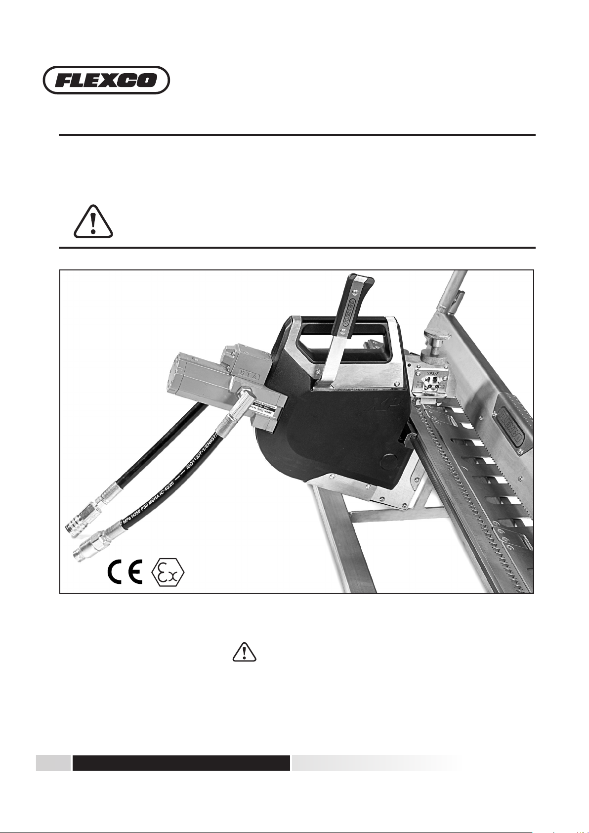
Hydraulic Flexco® XP™ Staple Fastener
Installation System
Safety, Operation, and Maintenance Manual
h I Mb
WARNING
Improper use of this tool can result in serious bodily injury! is manual contains important information about
product function and safety. Please read and understand this manual BEFORE operating the tool. Please keep this
manual available for other users and owners before they use the tool. is manual should be stored in a safe place.
www.flexco.com
www.flexco.com
Page 2

Hydraulic Flexco® XP™ Staple Fastener System
Table of Contents
Introduction .................................................................................................................................... 3
Tool Specications ..........................................................................................................................3
System Components .................................................................................................................. 4-6
General Safety Rules ................................................................................................................... 7-9
Operational Instructions .............................................................................................................10
Belt Preparation ............................................................................................................................11
Installation Instructions ........................................................................................................11-17
Troubleshooting Guide ................................................................................................................ 18
Power Diagram .............................................................................................................................19
CE Declaration ..............................................................................................................................20
Limited Warranty
Flexco warrants to the original purchaser that this product is free from defects in material and workmanship, and
agrees to repair or replace, at Flexco’s option, any defective product within 1 year from the date of purchase. is
warranty is not transferable. It only covers damage resulting from defects in material or workmanship, and it does not
cover conditions or malfunctions resulting from normal wear, neglect, abuse, accident or repairs attempted or made by
other than our regional repair center or authorized warranty service center.
To obtain warranty service, return the product at your expense together with proof of purchase to Flexco or a Flexco
authorized distributor.
ww w.flexco.com
—2—
Page 3
Hydraulic Flexco® XP™ Staple Fastener System
Introduction
Role of Applicator
e Hydraulic Staple Applicator is designed to be used with Flexco® XP Staple Fasteners.
Precision Built
Flexco tools are precision-built tools designed for precise, high volume installation. ese tools will deliver ecient, dependable
service when used correctly and with care. As with any ne power tool, for best performance, the manufacturer’s instructions must
be followed. Please study this manual before operating the tool and understand the safety warnings and cautions. e instructions
on installation, operation, and maintenance should be read carefully, and the manual kept for reference.
Flexco® XP™ Hydraulic Staple Applicator
Specifications
Overall weight 26 kg
Overall dimensions 559 mm x 482 mm
Operating pressure 110 bar, 11 Mpa, 1600 psi
Min. pressure 103 bar, 10.3 Mpa, 1500 psi
Max. pressure 117 bar, 11.7 Mpa, 1700 psi
Flow rate 7-9 L/m, 1.5-2 GPM
Hydraulic fluid MSHA approved fire resistant hydraulic fluid, MA approved #46 or equivalent (not included)
Coupling ISO 16028 compliant couplings, flat face quick release coupling
High pressure in: Female 3⁄8” body size
Low pressure return: Male ½” body size
Max. hose length
(hoses included with
Flexco power source
purchase)
10 meters, 32.8 feet
High pressure hose (smaller hose OD), each end has factory installed male and female 3/8” body size
couplings
Low pressure return hose (larger hose OD), each end has factory installed male and female 1/2” body size
couplings
—3—
Page 4
Hydraulic Flexco® XP™ Staple Fastener System
System Components
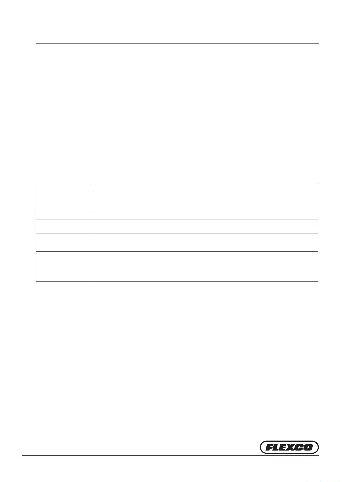
Flexco® XP™ Hydraulic Staple Applicator
1. Advance/actuation handle 6. Advance mechanism lever
2. Carrying handle 7. Hydraulic cylinder
3. Fastener compression adjustment knob and lock 8. High pressure in: 3/8” Female quick release coupling
4. Integrated belt thickness gauge 9. Low pressure return: 1/2” Male quick release coupling
5. Mounting bracket 10. Standalone belt thickness gauge
1
3
2
7
9
4
5
6
8
10
ww w.flexco.com
—4—
Page 5
Hydraulic Flexco® XP™ Staple Fastener System
System Components
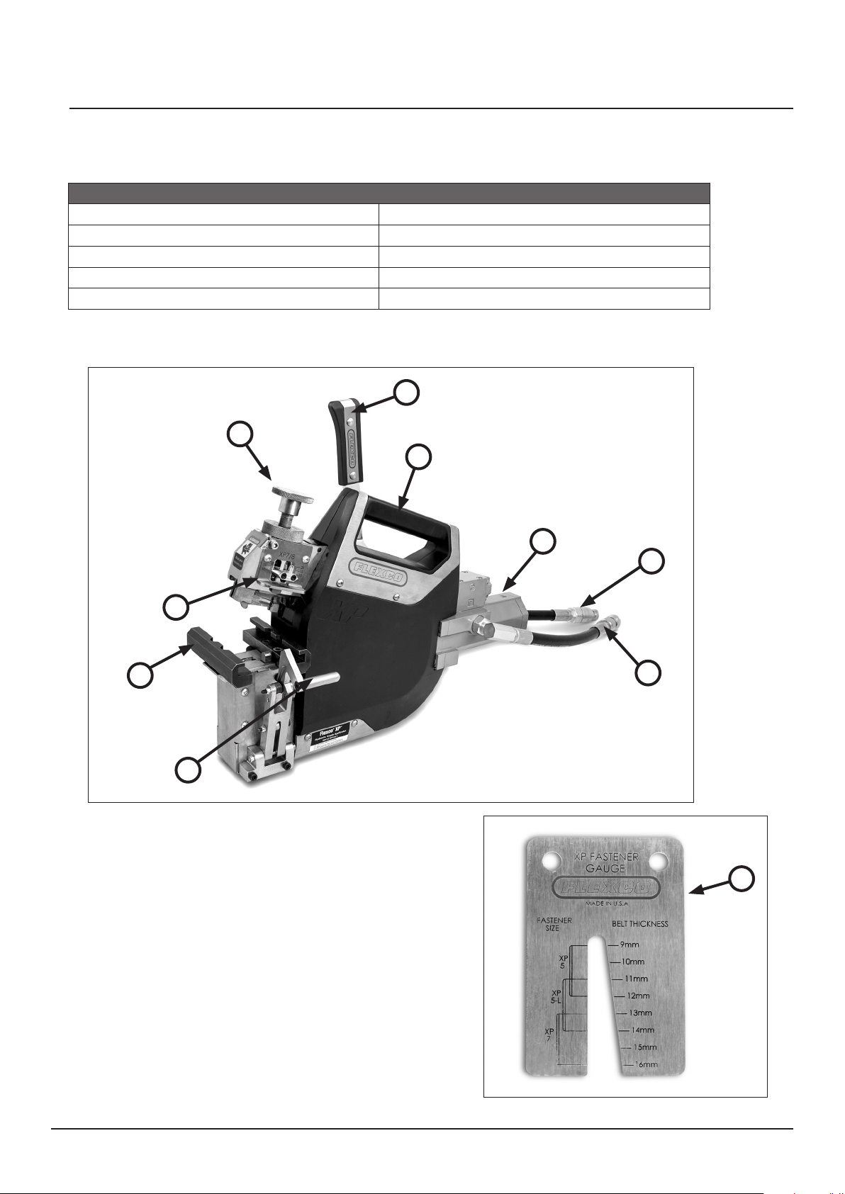
Flexco® XP™ Staple Tool Frame
1. Frame 4. Clamp bar
2. Belt guide plate 5. Bed
3. Clamp bar handle 6. Hydraulic staple applicator
6
4
3
5
2
1
—5—
Page 6
Hydraulic Flexco® XP™ Staple Fastener System
System Components
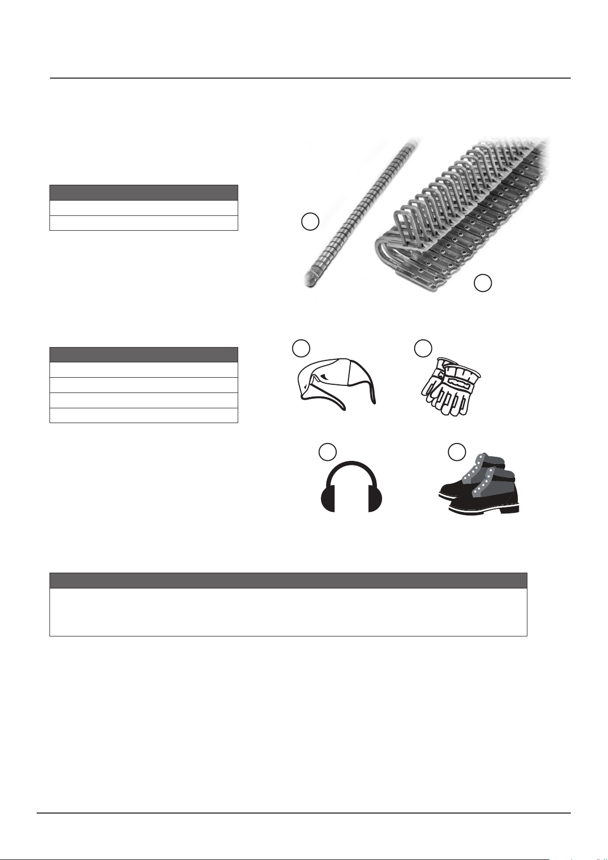
Flexco® XP™ Staple Fasteners
1. Fastener Strips
2. Hinge Pin
2
1
Protective Equipment
1. Safety Glasses
2. Gloves
3. Hearing Protection
4. Safety Shoes
Power Source
Immediate Need Power Pack
– For mobility throughout the mine
– OR –
1 2
3 4
Power Take-off Unit (PTO)
– For diverting hydraulic power from your conveyor at the mine
ww w.flexco.com
—6—
Page 7
Hydraulic Flexco® XP™ Staple Fastener System
General Safety Rules – Save These Instructions
Signal words
“DANGER” indicates an imminently hazardous situation which, if not avoided, will result
in death or serious injury. e signal word is
limited to the most extreme situations.
“WARNING” indicates a potentially hazardous
situation which, if not avoided, could result in
death or serious injury.
“CAUTION” indicates a potentially hazardous
situation which, if not avoided, may result in
minor or moderate injury. It may also be used to
alert against unsafe practices.
International Safety Symbol
!
is international safety symbol is used
to identify and call attention to specic
safetymatters.
Safety Information
To Avoid Severe Personal Injury or Property
Damage, read carefully and understand the
following Safety Precautions.
2. PERSONAL PROTECTIVE EQUIPMENT
!
WARNING
EYE PROTECTION which conforms to ANSI specications and provides protection against ying particles
both from the FRONT and SIDE should ALWAYS be
worn by the operator and others in the work area. Eye
protection is required to guard against ying debris,
which could cause severe eye injury.
e employer and/or user must ensure that proper
eye protection is worn. Eye protection equipment
must conform to the requirements of the Ameri- can
National Standards Institute, ANSI Z87.1 and provide
both frontal and side protection. NOTE: Non-side
shielded spectacles and face shields alone do not provide
adequate protection.
!
CAUTION
HEARING PROTECTION will be required in some
environments. For example, the working area may
include exposure to noise level which can lead to
hearing damage. e employer and user must ensure
that any necessary hearing protection is provided and
used by the operator and others in the work area.
!
CAUTION
HEAD PROTECTION – Some environments will
require the use of head protection equipment. When
required, the employer and user must ensure that
head protection conforming to ANSI Z89.1 is issued.
FOOT PROTECTION – Safety footwear should
always be worn. Operators must be protected against
falling tools and slippery conditions.
HAND PROTECTION – Safety gloves should always
be worn against hot surfaces and other sharp objects.
—7—
Page 8
Hydraulic Flexco® XP™ Staple Fastener System
General Safety Rules
3. PERSONAL SAFETY
!
WARNING
Do not use in explosive environments as this may result in serious personal injury.
Always handle the tool with care: 1.) Never engage in horseplay; 2.) Never pull the advance/actuation handle unless the
applicator is loaded onto the bed/frame base; 3.) Keep others a safe distance from the tool while tool is in operation as
accidental actuation may occur, possibly causing injury; 4.) Never place a hand or any part of body in the downward path of
the head applicator.
Potential Pinch Points
1. Adjustment Knob & Tool Cover
2. Tool Head & Clamp Bar
Potential Hot Surfaces
Do not operate the equipment if you are:
1.) Taking medication, feeling drowsy, feeling unwell or feeling tired; 2.) Under the inuence of drugs or alcohol; 3.) Experiencing
pain in hands, feet, lower back, or other parts of your body hurt or are injured. Failure to observe this precaution can result
serious injury or even death.
3. Tool Head & Bed (Fastener)
4. Hydraulic Tool & Frame
1
2
3
4
5
5. Clamp Bar & Bed (Belting)
6. Tool Advance & Cover Plate
6
!
CAUTION
Do not touch the machine with your bare hands: 1.) e oil tank may become hot under continuous running; 2.) Tools may
become hot under continuous use, make sure to wear safety gloves before any contact with the tools. Failure to observe this
precaution can result in burn injuries.
When lending someone the equipment, make sure the safety instructions have been thoroughly read and fully understood by
the person who is going to use the equipment.
ww w.flexco.com
—8—
Page 9

Hydraulic Flexco® XP™ Staple Fastener System
General Safety Rules
4. HYDRAULIC SAFETY
!
DANGER
is hydraulic tool is only designed to be used to
install Flexco XP staple fasteners. DO NOT operate
this hydraulic tool when: 1.) Part of the tool or whole
tool has been drenched in water or seawater; 2.) e
power source exceeds the oil ow and pressure range
prescribed; 3.) Operating with oil temperature below
10°C or over 100°C.
Do not operate hydraulic applicator unless it is
loaded onto the bed/frame base.
!
WARNING
At the beginning of each shi, conduct a TOOL
OPERATION CHECK: 1) Remove all fasteners from
tool before performing tool operation check; 2.) Do
not use if there is any oil leakage from hoses or tool
itself; 3) Do not use if there is damage to the tool.
Spilled hydraulic oil can cause burns, accidents
due to slippery conditions, and will also harm the
environment: 1) Take care of all spilled oil and
handle it according to your safety and environmental
regulations; 2) Avoid getting hydraulic oil on your
hands; 3) Always use protective gloves when working
with hydraulic oil; 4) Wash hands aer contact with
hydraulic oil.
At the end of operation, secure the tool to prevent
unauthorized use. Never assume you will nd the
equipment in the same condition in which you le it.
Never leave a tool unattended with the hoses
attached.
!
CAUTION
Always carry the tool by a handle.
Do not alter or modify this tool from the original
design or function without approval from FLEXCO.
Always be aware that misuse and improper handling
of this tool can cause injury to yourself and others.
5. MAINTENANCE SAFETY
!
DANGER
Always disconnect hydraulic hoses at tool and
electric supply at power pack when servicing the tool
or before making adjustments.
!
CAUTION
REPLACEMENT PARTS:
FLEXCO replacement parts are recommended. Do
not use modied parts or parts which will not give
equivalent performance to the originalequipment.
When using the machine to perform work-related
activities, you may experience discomfort in the hands,
arms, shoulders, neck, or other parts of the body: 1)
Adopt a comfortable posture while maintaining secure
footing and avoid awkward o-balanced postures; 2)
Changing posture during extended tasks may help
avoid discomfort and fatigue; 3) In case of persistent
or recurring symptoms, consult a qualied health
professional.
Do not store tool in a cold weather environment to
prevent frost or ice formation on the tool's operating
valves and mechanisms that could cause tool failure.
—9—
Page 10

Hydraulic Flexco® XP™ Staple Fastener System
Operational Instructions
Guidelines
1. When using hydraulic power units not manufactured by Flexco, make sure the operating pressure of the power unit is
110bar, 11 Mpa, 1600 psi and ow rate is in the range of 7-9 L/m (1.5-2 gpm).
2. When connecting and disconnecting couplings, make sure dirt, dust, and other foreign substances do not enter or attach to
coupling and hoses.
3. Make sure the power unit is OFF when connecting the hydraulic tool to the power unit.
!
4. If the oil temperature is below 10°C, warm up the hydraulic tool before operating.
!
5. Do not trip over the hydraulic hoses.
6. Make sure there are no jobsite obstacles.
!
7. Be cautious not to injure your back while liing the hydraulic tool.
!
8. In case of sudden hydraulic hose breakage STOP the power unit IMMEDIATELY.
!
9. Replace with new hoses when they are worn or when oil exudes from them.
10. When couplers detach, a small amount of oil may leak out. Make sure that surrounding area does not get drenched in oil.
11. To prevent dirt from entering the quick release couplings, be sure to clip couplings together aer disconnecting driver.
Couplings should be wiped down before clipping them together.
12. When detached from power source, attach two hoses to each other. Couplings should be wiped down before clipping
them together.
13. When frequently attached and detached to the power unit, hydraulic oil will decrease accordingly. Always check the
hydraulic oil level before operating and rell if necessary.
Tool Inspection
Examine the tool before applying fasteners.
• Clean any dirt build-up from the bed rails.
• Check the hydraulic applicator to make sure the mounting brackets are free from dirt build-up.
• Check for any nicks in the bed that may interfere with the movement of the head. Should any nicks be found, they should
be led o before using the tool.
• Ensure applicator moves freely on bed. If not spray SLP5 GLIDE silicone lubricant on bed rails and
mounting brackets for smoother operation.
• Inspect swipe arms, pusher tip and front/rear locator prongs for damage, chips or cracking. Replace
damaged parts by authorized distributor.
ww w.flexco.com
—10—
Page 11

Hydraulic Flexco® XP™ Staple Fastener System
R9
BR14 R6/R8
R5½
BR10 R5/190
BR6 140
Belt Preparation
1. Square belt using centerline method.
2. Cut belt at least 4" (100 mm) behind old splice
using Flexco belt cutting tool.
Installation Instructions
1. Select the Proper Fastener and Hinge Pin
a. Measure the belt thickness from cut edge
using belt gauge or tape measure.
b. determine the diameter of the smallest pulley
in the system which the belt will wrap at least 90º
(including the belt take up and storage unit) and
the mechanical fastener rating of the belt.
3. Skive belt when top cover permits. Adjust
fence on FSK2 skiver to the R5 setting for XP5/
XP5-L, half way between R5 and R5 1/2 for XP7,
and to the R5 1/2 setting for XP8.
Flexco® XP Staple Belt Fastener Selection Chart
A B C D
Fastener
Size
XP5 2000 1150 9-12 350 8.1
XP5-L 2000 1150 11-14 350 8.1
XP7 3500 2000 13-15 500 10.3
XP8 3500 2000 15-18 500 11.0
XP8-L 3500 2000 17-20 500 11.0
c. Refer to the table above to select the proper size fastener.
Belt
Strength
kN/m P.I.W. mm mm mm
Tension
Rating
Belt Thickness
Range
Recommended
Min. Pulley Diameter
—11—
Max. Hinge Pin
Diameter
Page 12

Hydraulic Flexco® XP™ Staple Fastener System
Installation Instructions (continued)
2. Load the Fasteners
1-1/2 inches
(38 mm)
a. Determine the exact number of fasteners needed for the belt by
laying strips of fasteners across the belt end. Center fasteners so that
approximately 1-1/2 inches (38 mm) of belt extends beyond the
fasteners on each edge.
b. If a shorter fastener strip is needed, hold strip in one hand and
carefully twist the strip with the other hand. Prior to placing in tool
bed, trim any welded wire that remains at the end of the shortened
strip so wire is ush with end fastener.
c. Center fastener strips within the bed.
• Insert the fasteners, with the open end of the fasteners toward the
clamp bar. e heads (crowns) of the staple will t into the slots
in the bed.
• Use rocking motion to guide staple pairs (two staples per fastener
plate) into each individual bed opening.
• Make sure there are no empty slots between fastener strips.
3. Load the Belt
BEST PRACTICE: Run crown side of staples on the carry side of the belt for optimal belt cleaner interface. Place carry side of
belt facing down in frame for installation.
a. Place belt on belt guide plate and slide the belt end under the
clamp bar and into the fastener.
ww w.flexco.com
b. Push the belt end into the fasteners until it is tight against the belt
stops which are built into the fasteners. If belt end rises above the
belt stop push the belt back so it is properly aligned.
—12—
Page 13

Hydraulic Flexco® XP™ Staple Fastener System
Installation Instructions (continued)
3. Load the Belt (Continued)
c. Center the belt so that approximately 1-1/2 inches (38 mm) of
belt extends beyond the fasteners on each edge.
d. Secure the belt in this position by evenly tensioning the clamp
bar handle on both ends of the clamp bar until the belt is securely
clamped.
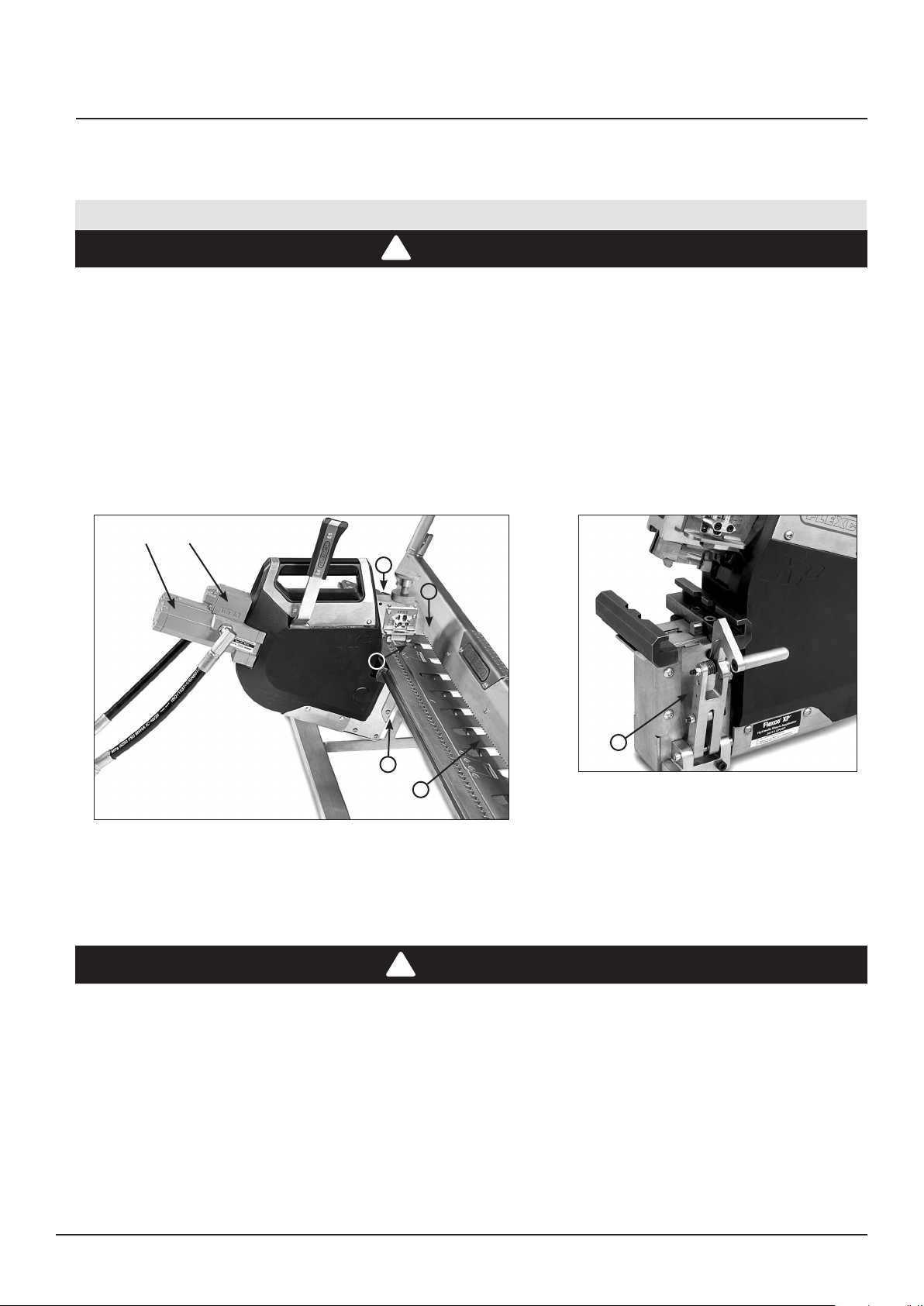
4. Load the Applicator
NOTE: Make sure to read the power source (Power pack or PTO) manual prior to operating the equipment.
a. Attach the hydraulic applicator to the bed by sliding the
mounting brackets located on the applicator onto the le end of the
bed rail. Ensure the advance/actuation handle is in the forward
position “0”.
b. Push the applicator rmly to the right until the tool is solidly on
the bed. Verify hydraulic hoses are not connected.
c. e applicator can be moved to the right either by continuing to
push it across the bed or by using the handle to rapidly advance the
head along the tool bed. e applicator can be moved to the le by
disengaging the advance mechanism lever and pushing the head to
the le.
—13—
2
d. To use the rapid advance feature move the advance/actuation
handle from start position “0” to positon “1” and repeat to quickly
advance the tool. Position the applicator over the rst two fasteners
in the fastener strip.
01
Page 14

Hydraulic Flexco® XP™ Staple Fastener System
Installation Instructions (continued)
5. Set the Belt Thickness Gauge
a. Insert sample belt end into the belt thickness gauge located on
the sides of the head. e side used is determined by the fastener
size that will be applied. For an XP7 fastener use the le side belt
gauge marked “XP7/XP8”. For an XP5 or XP5-L fastener use the
right side belt gauge marked “XP3/XP5”.
NOTE: If the belt doesn’t t into the gauge, the gauge is probably set from a previous use.
• Loosen the locking knob and open the gauge by turning the compression knob counter-clockwise several turns.
• Lock gauge in place by tightening the locking knob and remove belt from gauge. This setting is approximate.
b. Adjust the fastener compression knob until the belt just slides
in the gauge opening. Turn clockwise to tighten. Turn counterclockwise to loosen.
BEST PRACTICE: Use XPLT XP-LOK™ Tensioner
and XPLW-120 XP-LOK™ Belt Wire to prevent belt
wave and ripple on rubber plied belting.
Always perform a test sample to verify proper belt
thickness setting before completing nal installation.
A nal adjustment may be necessary aer the rst few
fasteners have been installed.
c. Use the stand alone belt thickness gauge as an
alternative when a belt sample is not available.
Correlate the belt thickness reference number marked
on the gauge and adjust fastener compression knob
accordingly.
ww w.flexco.com
—14—
Page 15

Hydraulic Flexco® XP™ Staple Fastener System
Installation Instructions (continued)
6. Connect Hydraulic Power
a. Make sure the hydraulic power source is in "OFF" position.
1. Connect the low pressure return hose (1⁄2" ID):
• Connect the male nipple (hose) to the female coupler at the power pack.
• Connect the female coupler (hose) to the male nipple at the hydraulic tool.
2. en connect the high pressure hose (3/8" ID):
• Connect the female coupler (hose) to the male nipple at the power pack.
• Connect the male nipple (hose) to the female coupler at the hydraulic tool.
NOTE: If quick release couplings are dicult to join, excess pressure has built up in the line. To relieve the pressure either turn the power pack o and on again
or move the advance/actuation handle one full cycle.
3. When making connections, do not over stretch the hoses or bend them at a sharp angle.
4. To disconnect the hose, pull the locking collar to release the connection at the hydraulic tool. Do not disconnect hose at power pack unless necessary. Fluid
spillage will result.
b. Connect hydraulic power pack to appropriate
electric source. WARNING: Make sure the power
source is not energized and follow proper LockOut/Tag-Out protocols.
Electrical examples (reference only):
Canada: 480VAC/575VAC, 3 phase, 60Hz
China: 380VAC/660VAC, 3 phase, 50Hz
Europe: 380VAC, 3 phase, 50Hz
US: 480VAC, 3 phase, 60Hz
PSI
c. Turn on the power source. d. Inspect gauges when tool is in idle mode. e
pressure gauge should read 110 bar, 11 Mpa,
1600psi. If the pressure gauge shows no pressure,
turn o the power source immediately. Examine
the power source connect with correct wiring.
—15—
Page 16

Hydraulic Flexco® XP™ Staple Fastener System
Installation Instructions (continued)
7. Fastener Installation
a. Move the advance/actuation handle from position “0’ to end of
travel (positon “2”). is action will result in the following sequence
of events: advance applicator to the next fastener, compress top
plate, drive staples, fold and swipe staple legs. Hold handle in
position “2” until feedback in handle is felt.
c. Examine the rst fasteners to ensure that the staple legs are
properly set. e leading edge of the fastener must be set tight on
the belt to reduce the fastener’s exposure to cleaner blades, skirt
rubbers, and return idlers.
NOTE: To prevent belt ripple, do not over compress fasteners on
the belt.
b. Push the advance/actuation handle forward (position “0”). is
action completes the drive cycle. Completed cycle time is about two
seconds.
1
2
d. Because belt thicknesses may vary across the width of the belt, it is
important to examine the fasteners as they are applied. If the top plate of
the fasteners is not tight on the belt, adjust the compression by turning
the adjustment knob (1) 1/4 turn to the right (clockwise), check and
repeat as necessary. If the applied fasteners appear to create a “ripple” in
the belt, the fasteners are over compressed. Adjust the compression by
turning the adjustment knob (1) 1/4 turn to the left (counter-clockwise),
check and repeat as necessary. Hold the compression position by
tightening the adjustment knob’s locking knob. (2).
e. Loosen clamp bar, remove belt, and repeat the fastener
installation procedure on the mating belt end.
ww w.flexco.com
f. When nished, turn o the power source. Pull back on lock collar
to disconnect hydraulic hoses.
—16—
Page 17

Hydraulic Flexco® XP™ Staple Fastener System
Installation Instructions (continued)
8. Complete the Splice
a. Insert the hinge pin. For ease of hinge pin insertion, overlap both
belt ends. Tent both ends and start to join loops from one side.
Insert hinge pin and continue to join the rest of loops.
d. Mark the splice date on the belt using the Flexco Belt
Identication Tool or other comparable method and record it in
your belt maintenance record.
Leading
edge
2
Direction of belt travel
c. Notch the trailing belt edge (1) and attach Flexco Hinge Pin
Retaining Collars (2) to maintain proper hinge pin position.
Trailing
edge
1
9. Tool Transport
NOTE: When transporting the tool over any distance, it is recommended that the hydraulic applicator be removed and carried separately. If you need to
move the tool a short distance or reposition it, it can be carried. Take care to keep the tool level and use two people to move it as the weight may not be
evenly distributed.
—17—
Page 18

Hydraulic Flexco® XP™ Staple Fastener System
Troubleshooting
Problem Cause Correction
Pull advance/actuation handle but
applicator does not advance
Pull advance/actuation handle down
but applicator does not actuate
Functioning but weak or low speed
Oil leakage from cylinder, hydraulic
hose, coupling
Power pack motor runs but there is no
pressure at the outlet
Staple legs are pushed up but staples
are only partially bent over
Staple legs are pushed up but staples
are not completely set
Belt has too much ripple or wave 1. Fastener compression was incorrectly
Staple legs are pushed up but staples
are not bent over
Cannot load applicator onto frame 1. Pilot punch is in up position
1. Advance mechanism lever was in disengage
position
2. Advance/setting handle was not pulled down to
position “1” to complete advance cycle
3. Advance/setting handle was not fully pushed
forward (position ”0”) to engage advance mechanism
4. Bed rails are dirty
5. Advance mechanism lever spring was not in position
or damaged (Rare)
1. Power pack unit is not turned ON
2. Hoses are not connected
3. Couplings are not connected properly
4. Power source relief valve pressure is set too low
5. No hydraulic pressure due to incorrect electric
cable connection at motor
1. Low fluid flow rate from power source unit
2. Relief valve pressure set too low
3. Back pressure is too high
4. Over-heated hydraulic fluid
1. Damage, wear or hardened O-ring
2. Damaged hose
3. Damaged connection at coupling
1. Motor turns in wrong direction due to incorrect
electric cable connection
2. Relief valve pressure is set too low
3. Relief valve stuck/malfunction
4. Low hydraulic fluid level
1. Operator did not wait for handle feedback at end
of the pull (position “2”) before returning handle to
start position “0”
1. Fastener compression was incorrectly
set (under-compress)
set (over-compress)
2. Using rubber plied belting
1. Damaged swipe arms
2. Damaged swipe linkages
2. Mounting brackets are not aligned properly
1. Engage advance mechanism lever
2. Pull handle down to position “1”
3. Push handle forward all the way to complete cycle
4. Clean surfaces and spray SLP5 GLIDE silicone
lubricant on bed rails and mounting brackets
5. Adjust or replace spring
1. Turn ON power pack unit
2. Connect hoses
3. Check if couplings have been connected properly
4. Adjust pressure to 110 bar, 11 Mpa, 1600 psi
5. Check proper electric cable connection, voltage,
and phases
1. Check electric cable connection, voltage, and
phases
2. Adjust pressure to 110 bar, 11 Mpa, 1600 psi
3. Use bigger diameter hose for return hose
4. Turn OFF power pack approximately one hour to
allow hydraulic fluid to cool
1. Replace O-ring by authorized distributor
2. Replace hose assembly
3. Replace hose assembly
1. Check proper electric cable connection, voltage,
and phases
2. Adjust pressure to 110 bar, 11 Mpa, 1600 psi
3. Replace relief valve by authorized distributor
4. Add hydraulic fluid accordingly
1. Pull advance/actuation handle down to position “2”
and wait for handle feedback prior to releasing
1. Adjust fastener compression by turning the
adjustment knob ¼ turn to right (clockwise) and
repeat as necessary
1. Adjust fastener compression by turning the
adjustment knob ¼ turn to left (counter-clockwise)
and repeat as necessary
2. Use XPLT XP-LOK™ Tensioner and XPLW-120
XPLOK™ Belt Wire to prevent belt wave and ripple
1. Replace swipe arms by authorized distributor
2. Replace swipe linkages by authorized distributor
1. Push advance/actuation handle to position “0” prior
to loading onto frame
2. Inspect and verify mounting bracket are properly
installed
ww w.flexco.com
—18—
Page 19

Hydraulic Flexco® XP™ Staple Fastener System
REV
REV DESC
DATE
100
RELEASE FOR PRODUCTION
PER ECR DG170368
4/28/17
2
4
35
6
Power Diagram
—19—
Page 20

Hydraulic Flexco® XP™ Staple Fastener System
CE Declaration
ww w.flexco.com
—20—
Page 21

Hydraulic Flexco® XP™ Staple Fastener System
—21—
Page 22

Hydraulic Flexco® XP™ Staple Fastener System
ww w.flexco.com
—22—
Page 23

Hydraulic Flexco® XP™ Staple Fastener System
—23—
Page 24

Flexco Europe GmbH • Leidringer Strasse 40-42 • D-72348 Rosenfeld • Germany
Tel: +49-7428-9406-0 • Fax: +49-7428-9406-260 • E-mail: europe@flexco.com
Visit www.flexco.com for other Flexco locations and products.
©2018 Flexible Steel Lacing Company. 05-17-19. For reorder: X4571
 Loading...