

Flexco Novitool PUN M 300, Novitool PUN M 600, Novitool PUN M 900 Safety And Operation Manual
Page 1
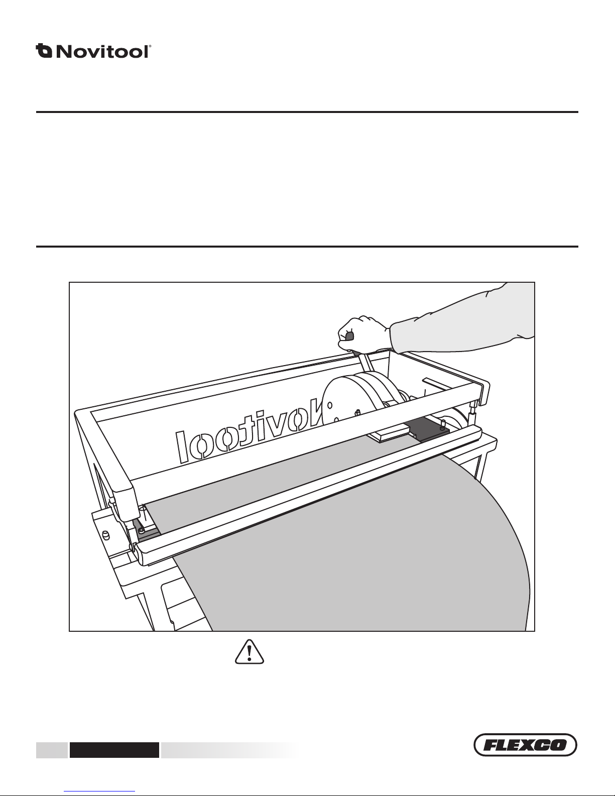
PUN M™ Manual Finger Punch
300 - 600 - 900
Safety and Operation Manual
For punching thermoplastic belting materials only.
IMPROPER OR UNSAFE use of this tool can result in serious bodily injury! is manual contains important information
about product function and safety. Please read and understand this manual BEFORE operating the tool. Please keep this
manual available for other users and owners before they use the tool. is manual should be stored in a safe place.
www.flexco.com
www.flexco.com
WARNING
Page 2

Table of Contents
Main Components .........................................................................................3
Description ..................................................................................................... 3
Tool Specications .........................................................................................4
General Safety Rules ......................................................................................5
Work Preparation and Replacing Punchboards ........................................ 7
Punching Single Fingers .............................................................................12
Punching Finger over Finger .....................................................................19
Bias Finger Punching ..................................................................................27
Bias Finger Over Finger Punching ............................................................ 32
Replacement Parts ....................................................................................... 41
Transportation Security .............................................................................. 42
ww w.flexco.com
—2—
Page 3
+
-
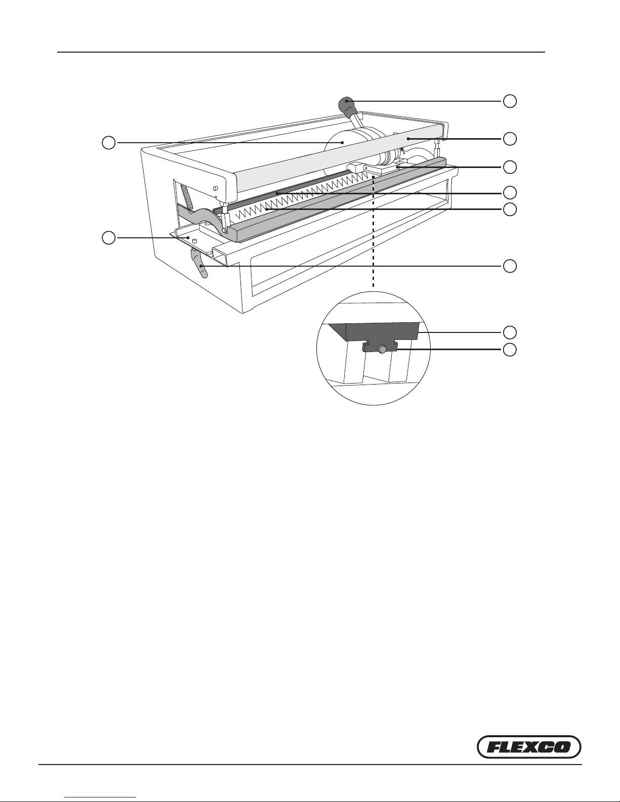
Main Components
1
7
8
1. C-Frame Handle
2. Belt Clamp Bar
3. Punchblock
4. Belt Stop
5. Punchboard with Finger Knives
2
3
4
5
6
9
10
6. Lock Handle
7. C-frame
8. Punchboard Tray
9. C-frame Wedge
10. Fixation Screw and Punching Force Adjustment
Description
e PUN M™ is designed to punch ngers on the ends of
lightweight thermoplastic conveyor belts as a preparation for
making nger- or nger-over-nger splices.
e Pun M is manually operated and does not need electricity
or air pressure for its operation. e punching force of
11,000lbs. (50 kN) is created by pulling the lever and is easily
done with one hand by an average person. Because of its easy
set-up and manual operation, the PunM is an ideal tool for
working on location, as well as in a workshop.
Although all punchboards of the Pun M have a specied net
width, the open construction of the frame allows belts of
larger widths to be punched with these machines.
With one lever pull, a nger punch of 90 mm wide can be
made (based on 50 × 20 ngers for nger-overlap-nger
splicing) or 60 mm wide (based on 80 × 20 or 70 × 15 ngers
for single nger splicing). e maximum thickness is up to
5mm for light weight belting.
—3—
Page 4
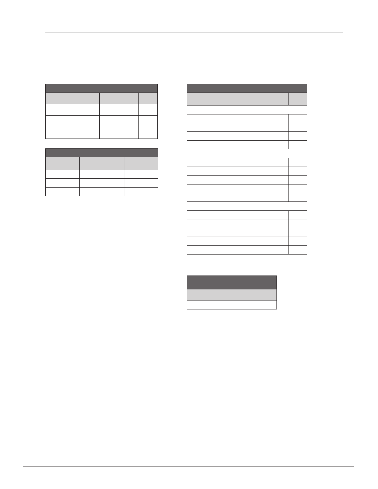
Tool Specifications
Pun M™ Dimensions
L H W Weight
Pun M 300
Pun M 600
Pun M 900
23"
570 mm
34"
870 mm
46"
1170 mm
15"
370 mm
15"
370 mm
15"
370 mm
14"
360 mm
14"
360 mm
14"
360 mm
Pun M™ Ordering Information
Ordering
Number
PUN-M-300 300 08016
PUN-M-600 600 08017
PUN-M-900 900 08018
Effective
Punching Length
Item Code
31 lbs
14 kg
37 lbs
17 kg
44 lbs
20 kg
Pun M™ Punchboard Specifications
Ordering Number
Pun M 300 Punchboards
1.97" × 0.79" (50 × 20 mm)* PUN-B-50x20-300 08019
2.76" × 0.59" (70 × 15 mm) PUN-B-70x15-300 08022
3.15" × 0.79" (80 × 20 mm) PUN-B-80x20-300 08025
1.97” x 0.71” (50 x 18 mm) PUN-B-50x18x31BIAS-300 08539
Pun M 600 Punchboards
1.97" × 0.79" (50 × 20 mm)* PUN-B-50x20-600 08020
2.76" × 0.59" (70 × 15 mm) PUN-B-70x15-600 08023
3.15" × 0.79" (80 × 20 mm) PUN-B-80x20-600 08026
1.97” x 0.71” (50 x 18 mm) PUN-B-50x18x31BIAS-600 08540
3.15” × 0.79” (80 × 20 mm) PUN-B-80x20x113BIAS-600 08439
Pun M 900 Punchboards
1.97" × 0.79" (50 × 20 mm)* PUN-B-50x20-900 08021
2.76" × 0.59" (70 × 15 mm) PUN-B-70x15-900 08024
3.15" × 0.79" (80 × 20 mm) PUN-B-80x20-900 08027
1.97” x 0.71” (50 x 18 mm) PUN-B-50x18x31BIAS-900 08526
3.15” × 0.79” (80 × 20 mm) PUN-B-80x20x113BIAS-900 08440
* Also suitable for Finger-Over-Finger splices.
** Custom Punch Boards Available Upon Request.
Item
Code
Pun M™ Punching Block
Nylon Inlay
Ordering Number Item Code
PUN-M-NYLONPAD-KIT 08279
ww w.flexco.com
—4—
Page 5
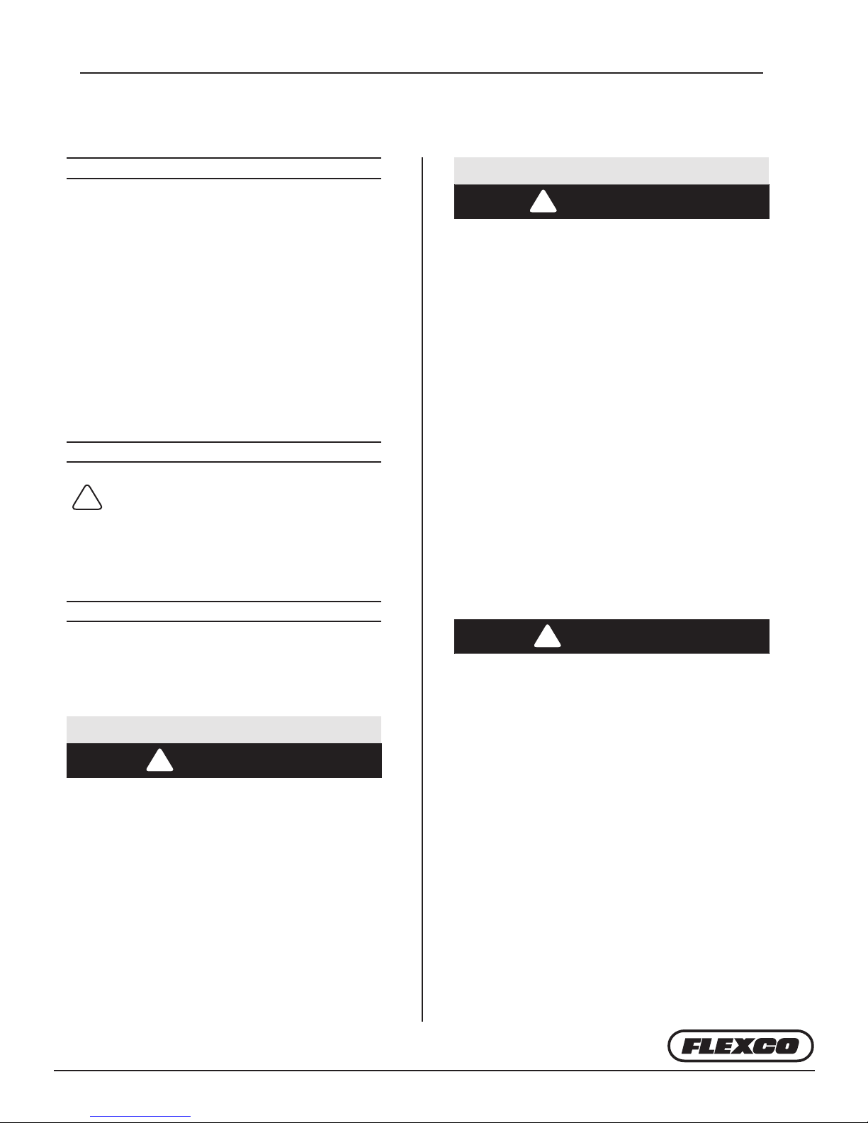
General Safety Rules
–Save These Instructions–
Signal words:
“DANGER” indicates an imminently hazardous
situation which, if not avoided, will result in
death or serious injury. e signal word is
limited to the most extreme situations.
“WARNING” indicates a potentially hazardous
situation which, if not avoided, could result in
death or serious injury.
“CAUTION” indicates a potentially hazardous
situation which, if not avoided, may result in
minor or moderate injury. It may also be used to
alert against unsafe practices.
Safety Symbol
!
is international safety symbol is used to
identify and call attention to specic
safety matters.
Safety Information
2. PERSONAL SAFETY
!
WARNING
Stay alert, watch what you are doing and use
common sense when operating a tool. Do not
use tool while tired or under the inuence of
drugs, alcohol, or medication. A moment of
inattention while operating tools may result in
serious personal injury.
Dress properly. Do not wear loose clothing
or jewelry. Contain long hair. Keep your hair,
clothing, and gloves away from moving parts.
Loose clothes, jewelry, or long hair can be
caught in moving parts.
Do not overreach. Keep proper footing and
balance at all times to enable better control of
the tool in unexpected situations.
Never alter or remove safety devices.
Keep your hands and ngers away from the
knives in the punchboard, at all times.
To Avoid Severe Personal Injury or Property
Damage, read carefully and understand the
following Safety Precautions.
1. WORK AREA
!
CAUTION
Keep your work area clean and well lit. Cluttered
benches and dark areas invite accidents.
!
CAUTION
Use safety equipment. Always wear eye
protection. Dust mask, non-skid safety shoes,
hard hat, or hearing protection must be used for
appropriate conditions.
—5—
Page 6
General Safety Rules
3. TOOL USE AND CARE
!
WARNING
Always use the punching machine on a level,
rm surface. Punching should be performed
operating the machine with one hand on the
handle and the other on the top part of the
frame or C-frame.
Tool service must be performed only by
qualied repair personnel. Service or
maintenance performed by unqualied
personnel could result in a risk of injury.
!
CAUTION
Maintain tools with care. Keep cutting tools
sharp and clean. Properly maintained tools,
with sharp cutting edges, are less likely to
require unnecessary high forces and are easier
to control. If damaged, have the tool serviced
before using. Many accidents are caused by
poorly maintained tools.
4. PUNCHBOARD SAFETY
AND REPLACEMENT
!
CAUTION
Always use original Flexco punchboards in
combination with the Pun M
Do not use dull or damaged punchboards.
Always protect yourself against the knives of
unused punchboards by shielding them with
cardboard packaging material or wood. is
material should also protect the knives from
getting damaged.
™
.
e Punching machine should not be used
to punch materials other than thermoplastic
belting materials. e thickness of the belting
material should never exceed 0.24 inch (6 mm).
When servicing a tool, use only original Flexco
replacement parts.
Do not wipe plastic parts with solvent. Solvents
such as gasoline, thinner, benzene, carbon
tetrachloride, and alcohol may damage and
crack plastic parts. Do not wipe them with such
solvents. Wipe plastic parts with a so cloth
lightly dampened with soapy water and
dry thoroughly.
www.flexco.com
—6—
Page 7
1
2
A
Work Preparation and Replacing Punchboards
A1
A2
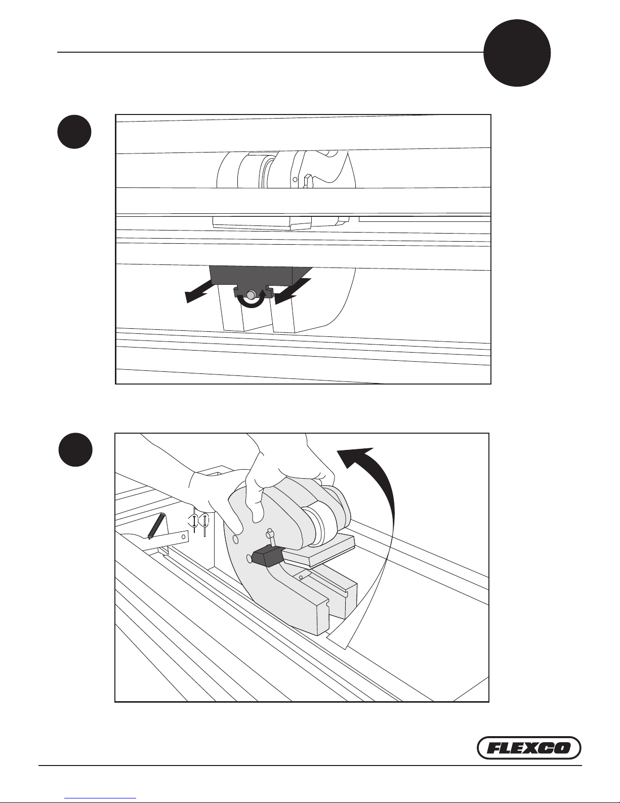
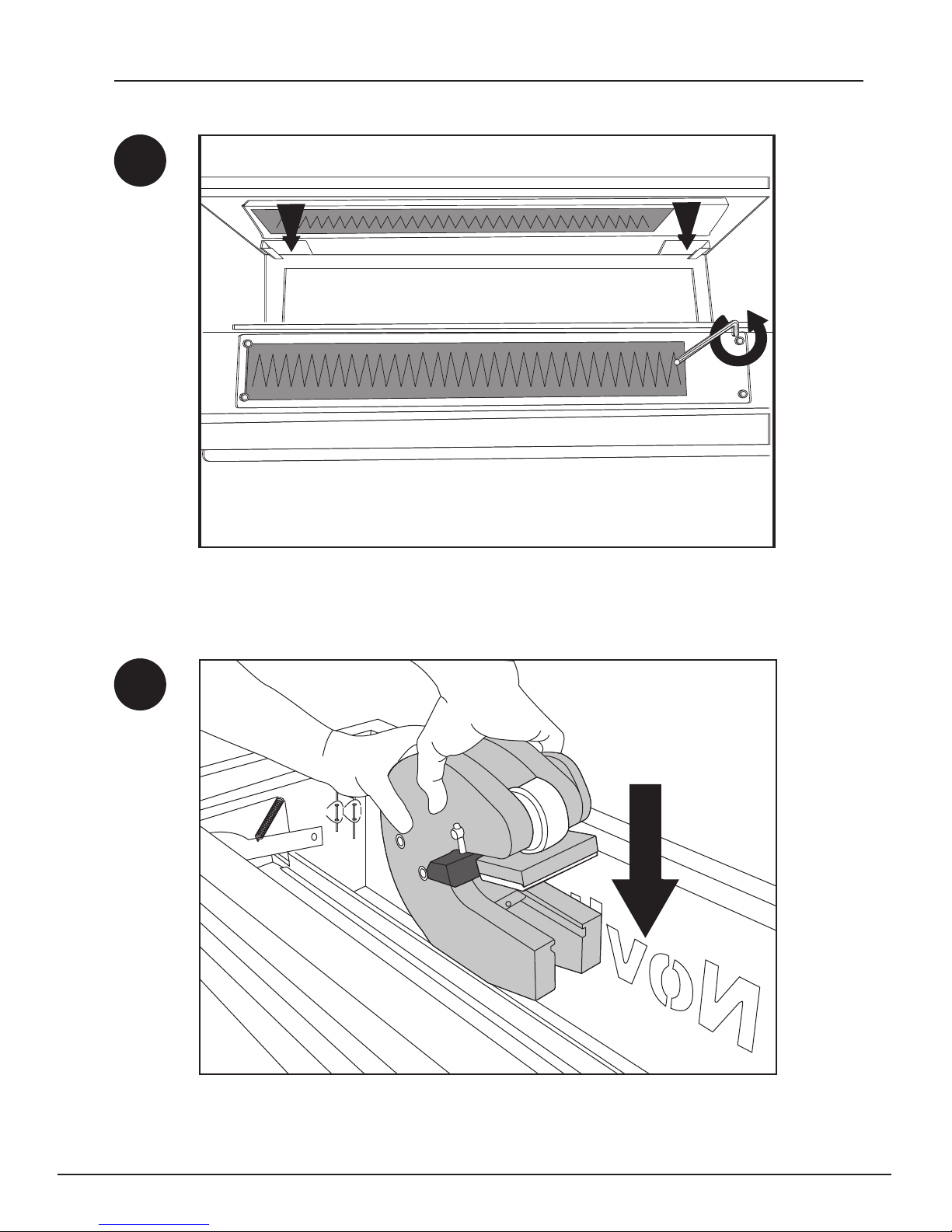
1. Loosen and remove xation screw. 2. Take out the black C-frame wedge.
Ensure tray is in forward position. Twist C-frame to remove.
—7—
Page 8
Work Preparation and Replacing Punchboards
A3
Pun-B-50×20
Pun-B-50×18×31 Bias
Pun-B-70×15
Pun-B-80×20
Pun-B-80×20×113 Bias
A4
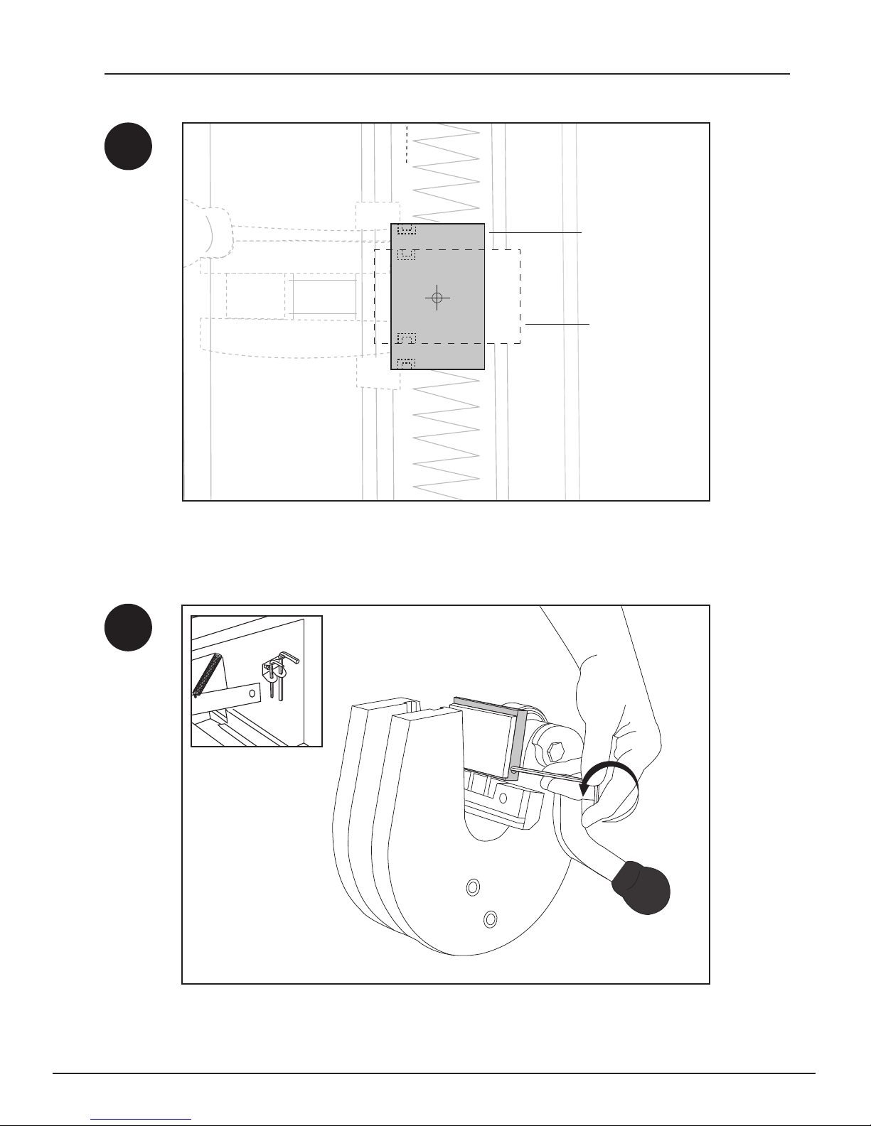
Determine required punchblock position.
Loosen set screw that holds punchblock in place when repositioning
isrequired.
ww w.flexco.com
—8—
Page 9
Work Preparation and Replacing Punchboards
A5
A6
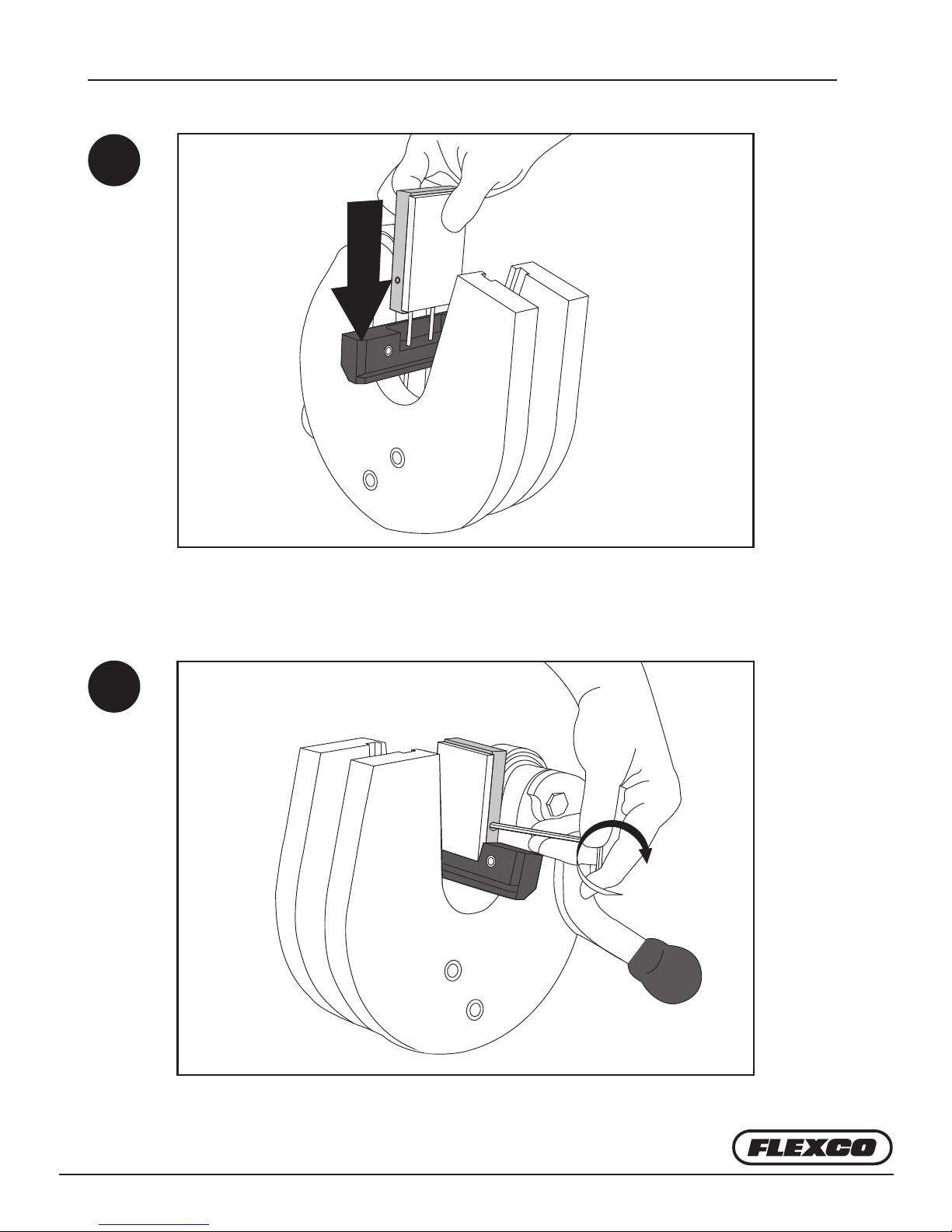
Slide punchblock over pins.
Secure punchblock with set screw.
—9—
Page 10
Work Preparation and Replacing Punchboards
A7
A8
Replace punchboard by unscrewing the four hex bolts. Stow unused
punchboard in holder on the back.
Reinstall C-frame.
ww w.flexco.com
—10—
Page 11
Work Preparation and Replacing Punchboards
A9
A10
2
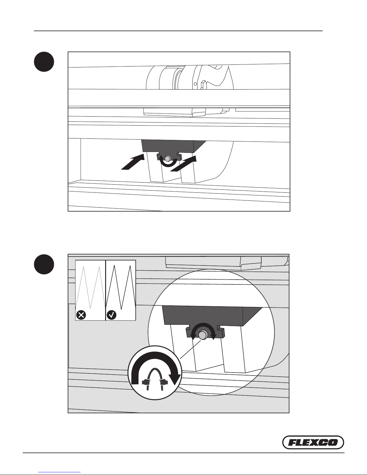
Secure C-frame. 1. Reinstall C-frame wedge. 2. Turn the xation screw to the
right. Attention: e screw is also used to adjust punching force.
1
Turn xation screw clockwise to increase punch cutting force.
-
+
—11—
Page 12
Punching Single Fingers
Prior to punching ensure:
• e punchblock is in the right position (A3)
• e correct punchboard is installed (A7)
• e punch force has been adjusted for material (A10)
B
B1
2
1
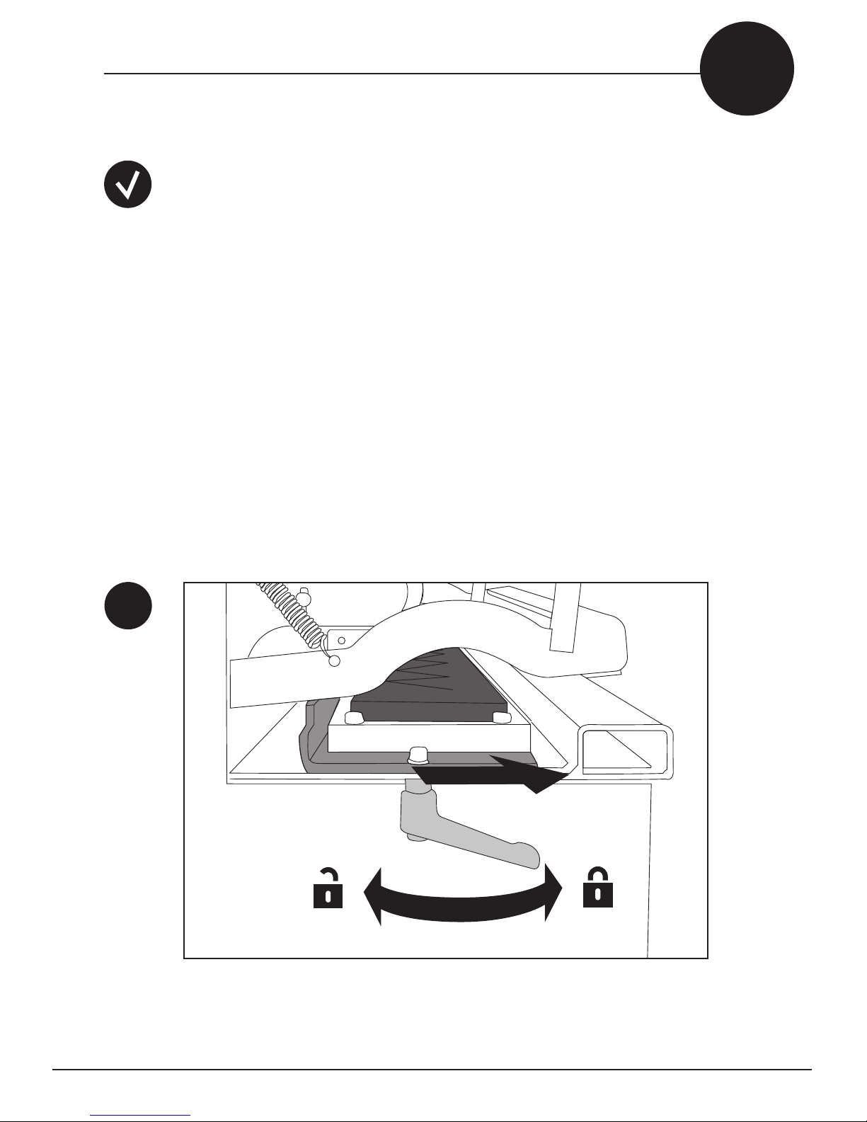
1. Unlock punchboard tray at both ends. 2. Move punchboard tray to front most
position. 3. Lock punchboard tray at both ends.
Attention: When required, reposition lock handle (A11).
3
ww w.flexco.com
—12—
Page 13

Punching Single Fingers
B2
B3
Pull lock handle down if repositioning is required to rmly lock tray.
Insert belt until ush against belt stop.
—13—
Page 14
Punching Single Fingers
B4
B5
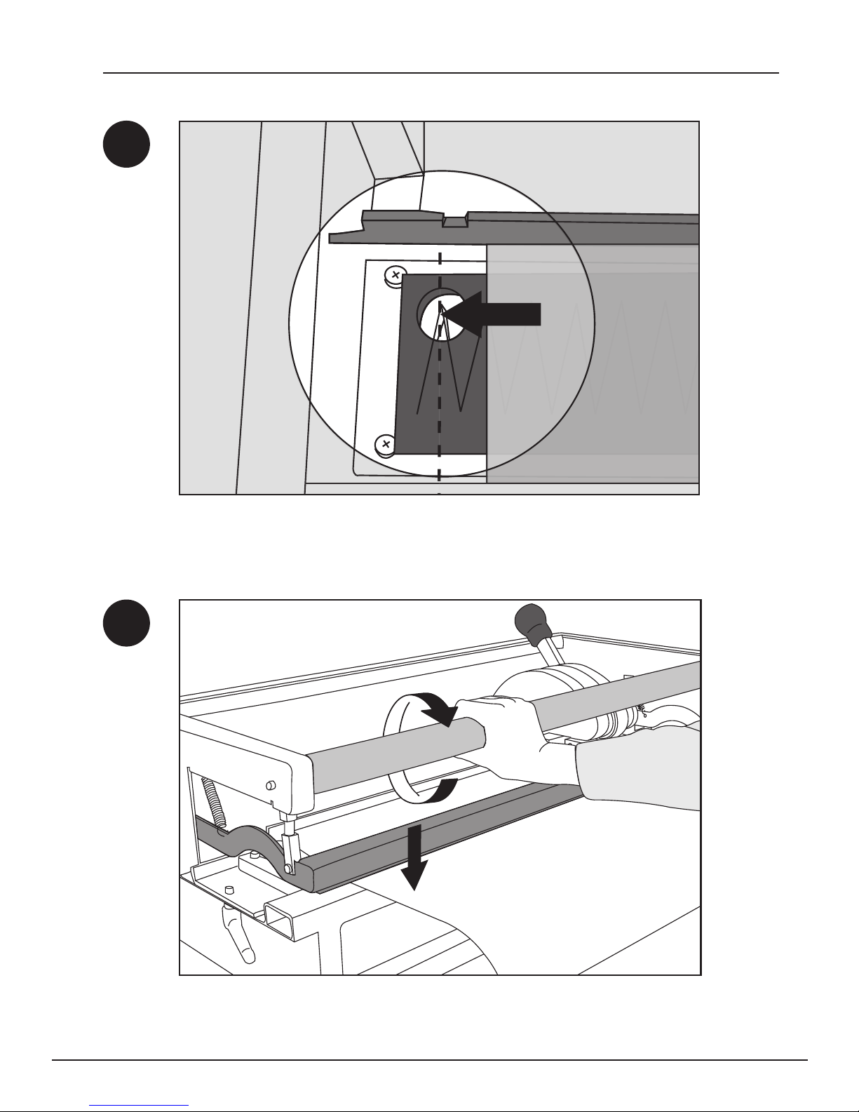
Le align belting material with top of V-Pattern in knife set.
Turn belt clamp bar to clamp belt.
ww w.flexco.com
—14—
Page 15

Punching Single Fingers
B6
B7
Place le hand on rear frame for support. Use other hand to operate lever to
punch belt. Punch in center, at both ends, and then across remainder of material.
Remove excess punched material.
Turn belt clamp bar. Remove belt.
—15—
Page 16

Punching Single Fingers
B8
2
IN
OUT
1
B9
Remove punched belt end. Install opposite belt end with cover side down into
the machine.
Insert belt end until ush with belt stop. Le align belt with the bottom of
V-Pattern in knife set.
ww w.flexco.com
—16—
Page 17

Punching Single Fingers
B10
B11
Turn belt clamp bar to clamp belt.
Repeat punching process as shown in B6.
—17—
Page 18

Punching Single Fingers
B12
Turn belt clamp bar. Remove belt.
ww w.flexco.com
—18—
Page 19

Punching Finger over Finger
Prior to punching ensure:
• e punchblock is in the right position (A3)
• e correct punchboard is installed (A7)
• e punch force has been adjusted for material (A10)
• Make sure belt ends are ply separated
C
C1
2
1
1. Unlock punchboard tray at both ends. 2. Move punchboard tray to front most
position. 3. Lock punchboard tray at both ends.
Attention: When required, reposition lock handle (B2).
3
—19—
Page 20

Punching Finger over Finger
C2
C3
Insert belt until ush against belt stop.
Align belt with top of V-Pattern in knife set.
ww w.flexco.com
—20—
Page 21

Punching Finger over Finger
C4
C5
Turn belt clamp bar to clamp belt.
Fold top layer of belt towards you.
—21—
Page 22

Punching Finger over Finger
C6
C7
Place le hand on rear frame for support. Use other hand to operate lever to
punch belt. Punch in center, at both ends, and then across remainder of material.
Remove excess punched material and loosen ngers from punch board prior to
sliding back the tray.
35 mm
2
Keep belt clamped. 1. Unlock punchboard tray at both ends. 2. Slide it to the
nal back position. 3. Lock punchboard tray at both ends.
ww w.flexco.com
1 3
—22—
Page 23

Punching Finger over Finger
C8
C9
Repeat punching process for second array of ngers. Again remove punched
excess material.
Turn belt clamp bar. Remove belt.
—23—
Page 24

Punching Finger over Finger
C10
2
C11
1
1. Unlock punchboard tray at both ends. 2. Move punchboard tray to front most
position. 3. Lock punchboard tray at both ends.
3
2
IN
OUT
1
Install opposite belt end with cover side down into the machine.
ww w.flexco.com
—24—
Page 25

Punching Finger over Finger
C12
C13
Insert belt end until ush with belt end stop. Le align belting material with
bottom of V-Pattern in knife set.
Repeat punching process as shown in C5-C6 for rst layer.
Repeat C7-C9 second layer.
—25—
Page 26

Punching Finger over Finger
C14
Turn belt clamp bar. Remove belt.
ww w.flexco.com
—26—
Page 27

Bias Finger Punching
Prior to punching ensure:
• e punchblock is in the right position (A3)
• e correct punchboard is installed (A7)
• e punch force has been adjusted for material (A10)
D
D1
4.8” (120 mm)
5:1 Ratio
24” : 4.8”
600 mm : 120 mm
4.8” (120 mm)
Prepare the belt ends for bias nger punching by cutting opposing (5:1 ratio) angles
on each belt end. NOTE: Both belt ends will be punched with the conveying side
upwards in the PUN M.
24” (600 mm)
Conveying Side
—27—
Page 28

Bias Finger Punching
D2
D3
Insert the initial belt end cover side up and ush against belt stop. Align the le
edge of belting with top of V-pattern in knife set.
Clamp the belt in place by rotating the belt clamp bar.
ww w.flexco.com
—28—
Page 29

Bias Finger Punching
D4
D5
Place le hand on rear frame for support. Use other hand to operate lever to
punch belt. Punch in center, at both ends, and then across remainder of material.
Remove excess punched material.
Turn belt clamp bar. Remove belt.
—29—
Page 30

Bias Finger Punching
D6
D7
Insert the opposite belt end cover side up into the Punch. Flush against belt.
Align right belt edge with bottom of V-pattern in knife set.
Turn belt clamp bar to clamp belt.
ww w.flexco.com
—30—
Page 31

Bias Finger Punching
D8
D9
Clamp the belt in place by rotating the belt clamp bar. Punch in center, at both
ends, and then across remainder of material.
Turn belt clamp bar. Remove belt.
—31—
Page 32

Bias Finger Over Finger Punching
Prior to punching ensure:
• e punchblock is in the right position (A3)
• e correct punchboard is installed (A7)
• e punch force has been adjusted for material (A10)
• Make sure belt ends are ply separated.
E
E1
E1
14.2” : (360 MM)
5:3 Ratio
24” : 14.2”
600 mm : 360 mm
14.2” : (360 MM)
Prepare the belt ends for bias nger over nger punching by cutting opposing
(5:3ratio) angles on each belt end. Use the Ply 130™ to separate each belt end to
4.3” (110 mm) depth.
24” (600 mm)
Conveying Side
ww w.flexco.com
—32—
Page 33

Bias Finger Over Finger Punching
E2
2
E3
1
1. Unlock punchboard tray at both ends. 2. Move punchboard tray to front most
position. 3. Lock punchboard tray at both ends.
Attention: When required, reposition lock handle (B2).
3
Insert initial belt end cover side up and ush against belt stop. Align the le
edge of the belting with the top of V-pattern in knife set.
—33—
Page 34

Bias Finger Over Finger Punching
E4
E5
Clamp belt in place by rotating belt clamp bar.
Place le hand on rear frame for support. Use other hand to operate lever to
punch belt. Li top layer of belt up. In this step you will only punch the bottom
layer. Punch in center, at both ends, and then across remainder of material.
ww w.flexco.com
—34—
Page 35

Bias Finger Over Finger Punching
E6
35 mm
2
E7
1 3
Keep belt clamped. 1. Unlock punchboard tray at both ends. 2. Slide it to nal
back position. 3. Lock punchboard tray at both ends.
Lay top cover down and repeat punching process for second array of ngers.
Remove excess punched material.
—35—
Page 36

Bias Finger Over Finger Punching
E8
E9
Turn belt clamp bar. Remove belt.
2
1. Unlock punchboard tray at both ends. 2. Move punchboard tray to front most
position. 3. Lock punchboard tray at both ends.
Attention: When required, reposition lock handle (B2).
ww w.flexco.com
1
3
—36—
Page 37

Bias Finger Over Finger Punching
E10
E11
Insert opposite belt end cover side up and ush against belt stop. Align right
belt edge with bottom of V pattern in knife set.
Turn belt clamp bar. Remove belt.
—37—
Page 38

Bias Finger Over Finger Punching
E12
E13
Li top layer of belt up and then tuck the bottom layer under the
punchboardtray.
Once bottom layer is out of the way, lay top layer down and punch belt. Place le
hand on rear frame for support. Use other hand to operate lever to punch belt.
Punch in center, at both ends, and then across remainder of material. Remove
excess punched material.
ww w.flexco.com
—38—
Page 39

Bias Finger Over Finger Punching
E14
E15
Keep belt clamped. 1. Unlock punchboard tray at both ends. 2. Slide it to nal back
position. 3. Lock punchboard tray at both ends (=1.38”/35mm displacement).
Li top layer up of belt up and reposition bottom layer over punchboard. In
this step you will only punch the bottom layer. Punch in center, at both ends,
and then across remainder of material. Remove excess punched material.
—39—
Page 40

Bias Finger Over Finger Punching
E16
Turn belt clamp bar. Remove belt.
ww w.flexco.com
—40—
Page 41

+
-
Replacement Parts
F
1
7
8
Replacement Parts
POSITION DESCRIPTION
C-frame Handle Grip PUN-M-CFRAMEHNDLGRIP 08197
1
Belt Clamp Bar for
PunM 300
Belt Clamp Bar for
2
PunM 600
Belt Clamp Bar for
PunM 900
3 Complete Punchblock PUN-M-PUNCH-PLATE 08128
Component
of 3
Replacement Nylon
Punchpad and Tape
5 Torsion Bushing FGTBSG 56521
ORDERING
NUMBER
PUN-M-ACTUATORBAR-300 08182
PUN-M-ACTUATORBAR-600
PUN-M-ACTUATORBAR-900 08184
PUN-M-NYLONPAD 08279
ITEM
CODE POSITION DESCRIPTION
Lock Handle for
6
Punchboard Tray
Punchboard Support
08183 Punchboard Support
10
Table for PunM 300
8
Table for PunM 600
Punchboard Support
Table for PunM 900
C-frame Wedge
Wedge Hardware Kit
(plastic cap, locking
collar, adjusting bar)
2
3
4
5
6
9
10
ORDERING
NUMBER
PUN-M-TABLELEVER 08191
PUN-M-TABLE-300 08188
PUN-M-TABLE-600 08189
PUN-M-TABLE-900 08190
PUN-MADJUSTERWEDGE
PUN-MADJUSTINGWEDGEHARDWARE
ITEM
CODE
08194
08713
PUN M™ Manual Punch
ORDERING
NUMBER
PUN M* PUN M 600 PUNCHBOARDS PUN M 900 PUNCHBOARDS
PUN-M-300 08016 PUN-B-50×20-600 08020 PUN-B-50×20-900 08021
PUN-M-600 08017 PUN-B-70×15-600 08023 PUN-B-70×15-900 08024
PUN M 300 PUNCHBOARDS PUN-B-50×18×31BIAS-600 08540 PUN-B-50×18×31BIAS-900 08526
*Punchboards not included with Pun M; purchase separately.
Note: Custom punchboards are available for other finger dimensions. Contact Customer Service for information.
PUN-M-900 08018 PUN-B-80×20-600 08026 PUN-B-80×20-900 08027
PUN-B-50×20-300 08019 PUN-B-80×20×113BIAS-600 08439 PUN-B-80×20×113BIAS-900 08440
PUN-B-70×15-300 08022 REPLACEMENT PARTS
PUN-B-80×20-300 08025 PUN-M-NYLONPAD-KIT 08279
PUN-B-50X18X31BIAS-300 08539
ITEM
CODE
ORDERING
NUMBER
—41—
ITEM
CODE
ORDERING
NUMBER
ITEM
CODE
Page 42

Transportation Security
F1
G
Position C-frame to middle of punchboard tray and slide locking pin into hole.
ww w.flexco.com
—42—
Page 43

Page 44

2525 Wisconsin Avenue • Downers Grove, IL 60515-4200 • USA
Tel: (630) 971-0150 • Fax: (630) 971-1180 • E-mail: info@flexco.com
Visit www.flexco.com for other Flexco locations and products.
©2018 Flexible Steel Lacing Company. 11/15/18. For reorder: X2347
 Loading...