

Flexco H-Type Primary Cleaner with V-Tips, H-Type HV with PCST Tensioner, H-Type HV with Bolt Tensioner Installation, Operation And Maintenance Manual
Page 1
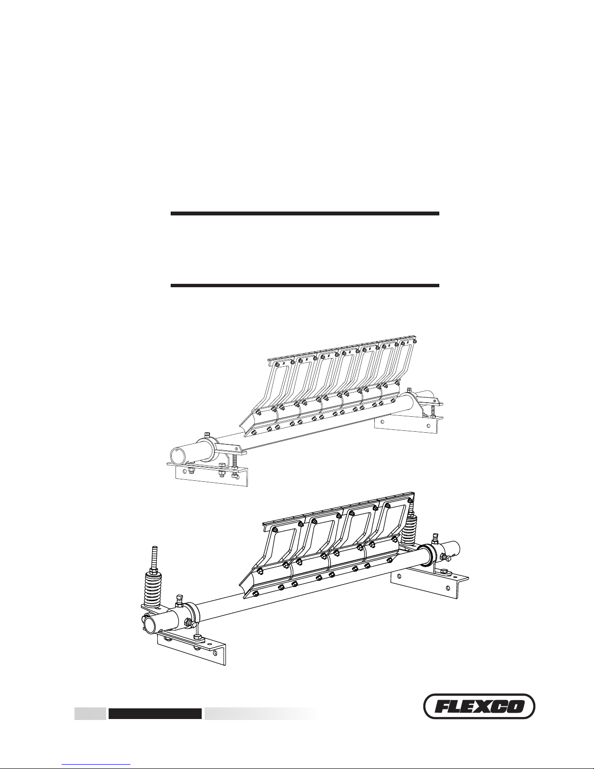
H-Type® Primary Cleaner with V-Tips
Installation, Operation
and Maintenance Manual
www.flexco.com
www.flexco.com
HV with Bolt Tensioner
HV with PCST Tensioner
Page 2

H-Type® Primary Cleaner with V-Tips
Purchase Date: ______________________________________________________________
Purchased From: ____________________________________________________________
Installation Date: ____________________________________________________________
This information will be helpful for any future inquiries or questions
about belt cleaner replacement parts, specifications or troubleshooting.
Page 3

3
Table of Contents
Section 1 – Important Information ...........................................................................................................4
1.1 General Introduction ..................................................................................................................................4
1.2 User Benets ................................................................................................................................................4
1.3 Service Option .............................................................................................................................................4
Section 2 – Safety Considerations and Precautions ..................................................................................5
2.1 Stationary Conveyors ..................................................................................................................................5
2.2 Operating Conveyors ..................................................................................................................................5
Section 3 – Pre-Installation Checks and Options ......................................................................................6
3.1 Checklist .......................................................................................................................................................6
Section 4 – Installation Instructions..........................................................................................................7
4.1 H-Type® Primary Cleaner with V-Tips ..................................................................................................7
4.2a H-Type® Primary Cleaner with V-Tips - Chute Mounting .................................................................8
4.2b H-Type® Primary Cleaner with V-Tips - Open Head Mounting ......................................................10
4.3 H-Type® Primary Cleaner with V-Tips - Bolt Tensioner ...................................................................11
4.4 H-Type® Primary Cleaner with PCST Tensioner ................................................................................13
4.5 H-Type® Primary Cleaner with PCST Tensione- Bolt Tensiner .......................................................15
Section 5 – Cleaner Pole Location Charts ...............................................................................................17
5.1 Pole Location Charts .................................................................................................................................17
Section 6 – Pre-Operation Checklist and Testing....................................................................................20
6.1 Pre-Op Checklist .......................................................................................................................................20
6.2 Test Run the Conveyor ..............................................................................................................................20
Section 7 – Maintenance ..........................................................................................................................21
7.1 New Installation Inspection .....................................................................................................................21
7.2 Routine Visual Inspection ........................................................................................................................21
7.3 Routine Physical Inspection .....................................................................................................................21
7.4 Blade Replacement Instructions ..............................................................................................................22
7.5 Maintenance Log .......................................................................................................................................24
7.6 Cleaner Maintenance Checklist ...............................................................................................................25
Section 8 – Troubleshooting ....................................................................................................................26
Section 9 – Specs and CAD Drawings......................................................................................................27
9.1 Specications and Guidelines ..................................................................................................................27
9.2 CAD Drawings...........................................................................................................................................28
Section 10 – Replacement Parts List ........................................................................................................31
Section 11 – Other Flexco Conveyor Products ........................................................................................ 35
Page 4

4 H-Type® Primary Cleaner with V-Tips
Section 1 – Important Information
We at Flexco are very pleased that you have selected an H-Type® Primary Cleaner with V-Tips for your
conveyor system.
is manual will help you to understand the operation of this product and assist you in making it work up to
its maximum eciency over its lifetime of service.
It is essential for safe and ecient operation that the information and guidelines presented be properly
understood and implemented. is manual will provide safety precautions, installation instructions,
maintenance procedures and troubleshooting tips.
If, however, you have any questions or problems that are not covered, please visit our web site or contact our
Customer Service Department:
Customer Service: 612-8818-2000
Visit www.flexco.com for other Flexco locations and products.
Please read this manual thoroughly and pass it on to any others who will be directly responsible for
installation, operation and maintenance of this cleaner. While we have tried to make the installation and
service tasks as easy and simple as possible, it does however require correct installation and regular
inspections and adjustments to maintain top working condition.
1.2 User Benets
Correct installation and regular maintenance will provide the following benets for your operation:
• Reduced conveyor downtime
• Reduced man-hour labor
• Lower maintenance budget costs
• Increased service life for the belt cleaner and other conveyor components
1.3 Service Option
e H-Type Primary Cleaner with V-Tips is designed to be easily installed and serviced by your on-site
personnel. However, if you would prefer complete turn-key factory service, please contact your local Flexco
Field Representative.
1.1 General Introduction
Page 5

5
Before installing and operating the H-Type® Primary Cleaner with V-Tips, it is important to review and understand
the following safety information.
There are set-up, maintenance and operational activities involving both stationary and operating conveyors. Each
case has a safety protocol.
2.1 Stationary Conveyors
The following activities are performed on stationary conveyors:
• Installation • Blade replacement • Repairs
• Tension adjustments • Cleaning
Section 2 – Safety Considerations and Precautions
DANGER
DANGER
WARNING
WARNING
WARNING
!
!
!
!
!
It is imperative that Lockout/Tagout (LOTO) regulations, be
followed before undertaking the preceding activities. Failure
to use LOTO exposes workers to uncontrolled behavior of
the belt cleaner caused by movement of the conveyor belt.
Severe injury or death can result.
Before working:
• Lockout/Tagout the conveyor power source
• Disengage any takeups
• Clear the conveyor belt or clamp securely in place
Use Personal Protective Equipment (PPE):
• Safety eyewear
• Hardhats
• Safety footwear
Close quarters, springs and heavy components
create a worksite that compromises a worker’s eyes,
feet and skull.
PPE must be worn to control the foreseeable
hazards associated with conveyor belt cleaners.
Serious injuries can be avoided.
2.2 Operating Conveyors
There are two routine tasks that must be performed while the conveyor is running:
• Inspection of the cleaning performance
• Dynamic troubleshooting
Every belt cleaner is an in-running nip hazard. Never
touch or prod an operating cleaner. Cleaner hazards
cause instantaneous amputation and entrapment.
Never adjust anything on an operating cleaner.
Unforseeable belt projections and tears can catch
on cleaners and cause violent movements of the
cleaner structure. Flailing hardware can cause
serious injury or death.
Belt cleaners can become projectile hazards. Stay as far
from the cleaner as practical and use safety eyewear and
headgear. Missiles can inflict serious injury.
Page 6

6 H-Type® Primary Cleaner with V-Tips
Section 3 – Pre-installation Checks and Options
• Check that the cleaner size is correct for the beltline width
• Check the belt cleaner carton and make sure all the parts are included
• Review the “Tools Needed” list on the top of the installation instructions
• Check the conveyor site:
- Will the cleaner be installed on a chute
- Is the install on an open head pulley requiring mounting structure
- Are there obstructions that may require cleaner location adjustments
3.1 Checklist
Page 7
7
4.1 H-Type© Primary Cleaner with V-Tips
Section 4 – Installation Instructions
Before You Begin:
• Installation specs and instructions are based on the assumption
that the conveyor is in its working position (angle). If the
conveyor angle will be different, the cleaner should be installed
per the final position.
• Choose instructions for chute mounting or open head
mounting. For chute mounting it may be necessary to cut
an access hole to allow for installation and inspections.
(See dimensions in Step 7 under Chute Mounting.)
• Follow all safety precautions when using a cutting torch.
• If welding, protect all fastener threads from weld spatter.
Maximum
lump size +
200mm
Chute wall
Space needed to avoid clogging chute
V-Tip Size Pulley Diameter + Belt and Lagging
SS up to 499mm
S 500-799mm
M 800-999mm
L 1000-1199mm
LL 1200-1700mm
Tools Needed
• Tape Measure
• 19mm Wrench
• Ratchet With 19mm Socket
• Adjustable Wrench
• Cutting Torch and/or Welder
• (2) 150mm C-Clamps (For Temporary
Positioning of Mounting Brackets)
• 600mm Level
• Marking Pen
Physically lock out and tag the conveyor at the power source
before you begin cleaner installation.
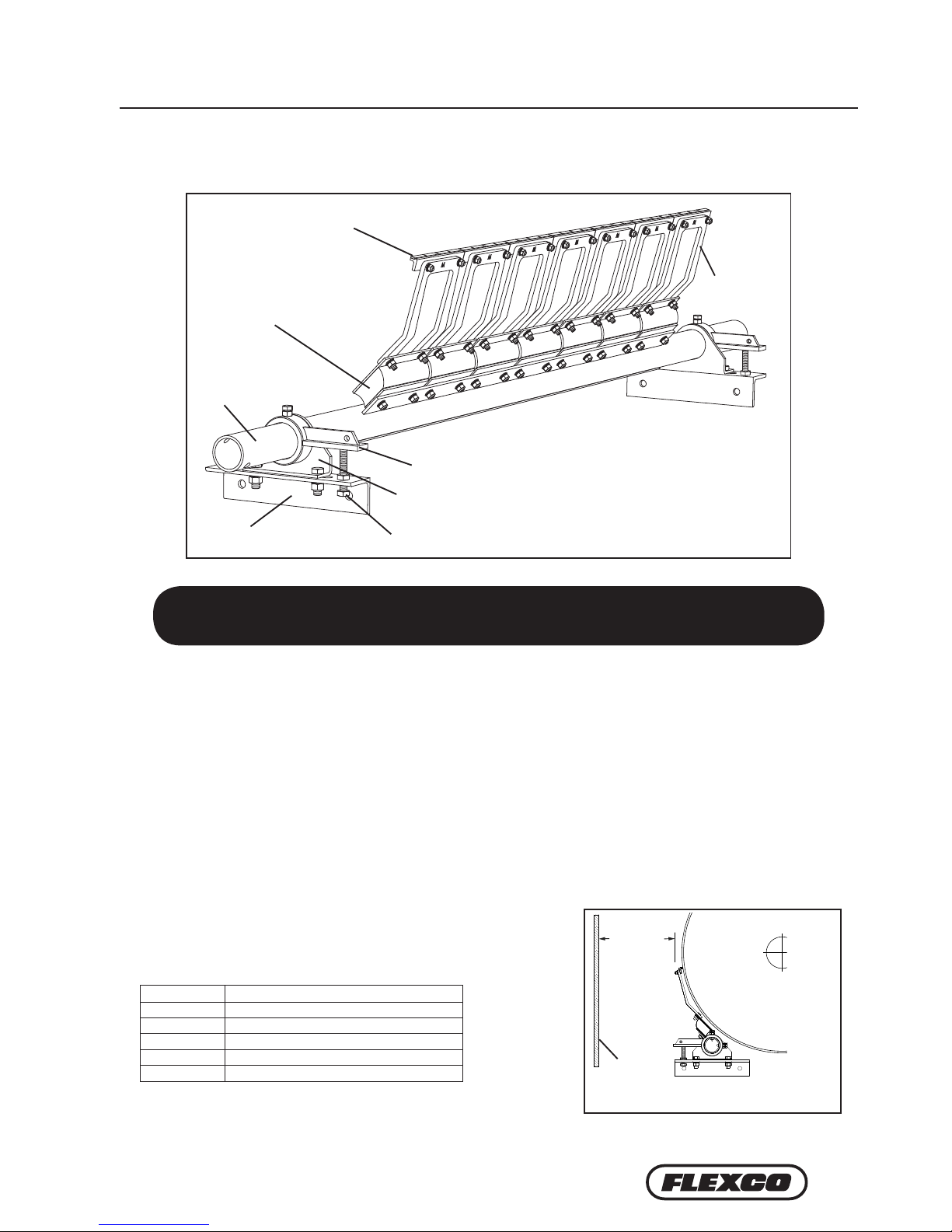
V-TIP
CUSHION
BEARING BLOCK
POLE
MOUNTING BRACKET
SUSPENSION
ARM
ADJUSTING ARM
ADJUSTING BOLT
Page 8
8 H-Type® Primary Cleaner with V-Tips
4.2a H-Type© Primary Cleaner with V-Tips
Section 4 – Installation Instructions
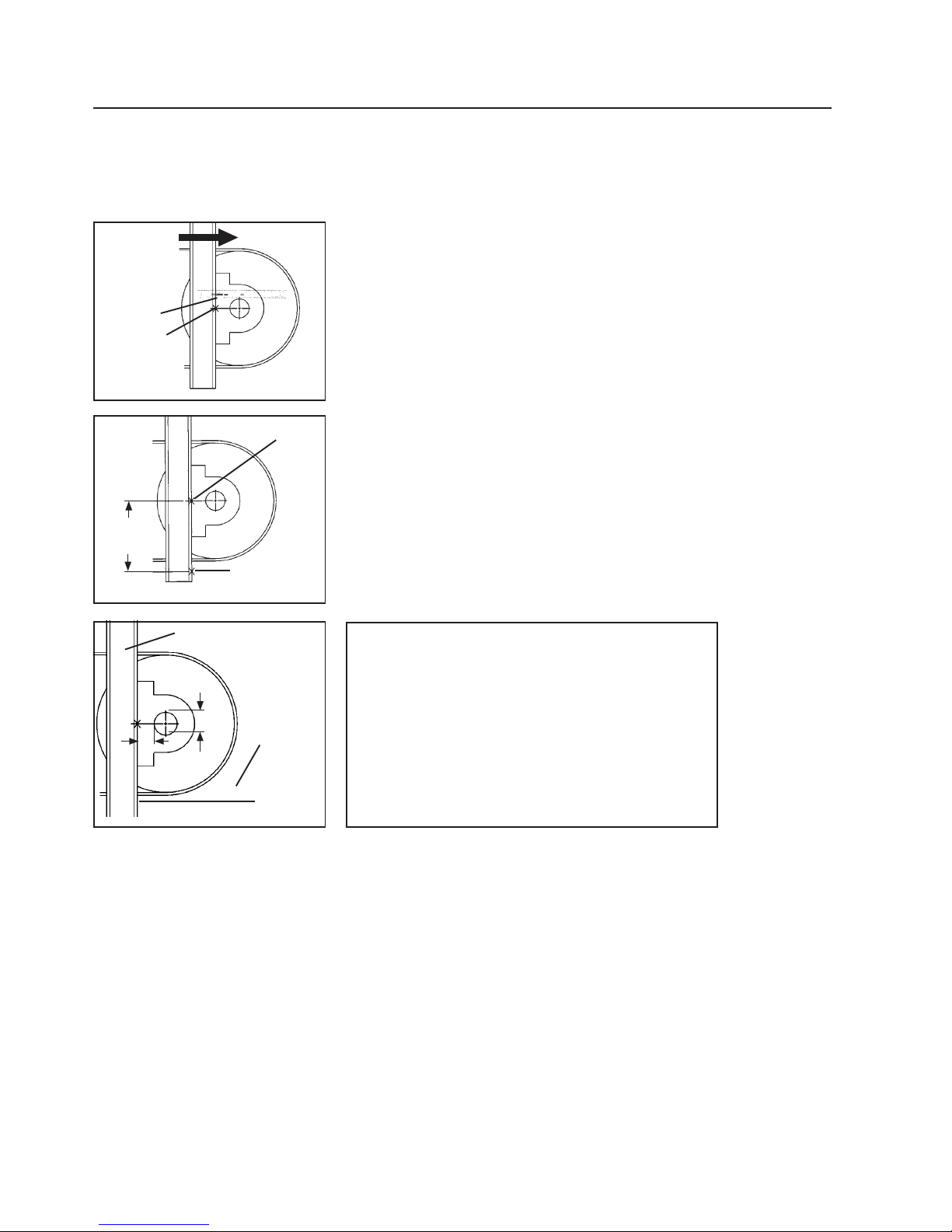
1. Find X and Y measurements. Find the X and Y measurement specifications for the pulley diameter. See charts
on pages 14, 15 and 16. The pulley diameter measurement should include lagging and belt.
Pulley Diameter _________mm; X = _________mm; Y = _________mm
Using the correct X and Y coordinates will position the cleaner at 15° below the horizontal plane on the head
pu lley.
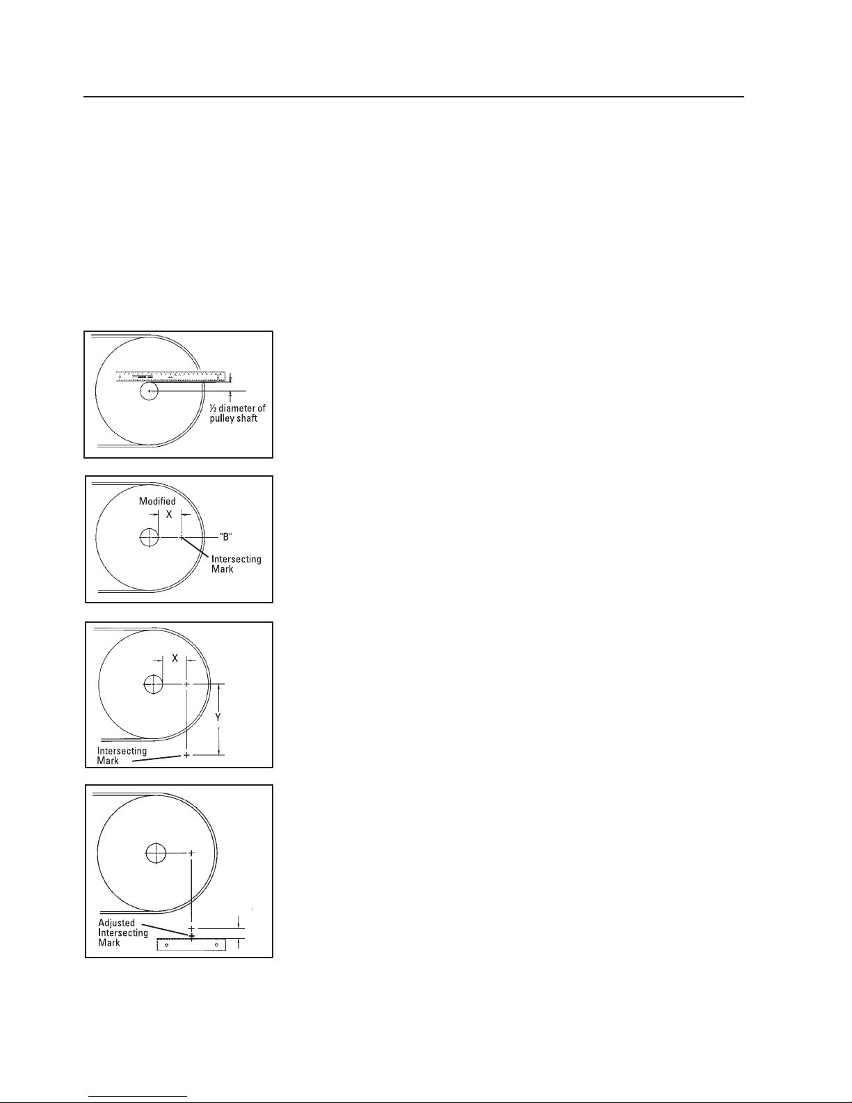
Fig. 1
Fig. 2
Fig. 2b
4. Locate mounting bracket position (horizontal position). To locate the
position of the cleaner mounting bracket, add 70mm to the intersecting
mark (Fig. 2b). This mark indicates the top centre of the mounting bracket.
Fig. 2a
2a. Measure head pulley shaft. Determine the diameter of the pulley shaft
and divide by 2.
2b. Put a level on top of the pulley shaft and draw a horizontal line A.
Measure down from Line A half the diameter of the pulley shaft and draw
Line B parallel from the pulley shaft (Fig. 1).
3a. Mark X dimension. Subtract the above dimension (Step 2a) from the
selected X dimension to establish the modified X dimension. With this
new X dimension measure horizontally from the front of the pulley shaft
forward on Line B and mark on the chute (Fig. 2).
3b. Determine Y dimension. From the horizontal X mark, drop a line
vertically down to the selected Y dimension and draw an intersecting mark
(Fig. 2a). This is the correct position of the centre of the pole.
Chute Mounting
70mm
Page 9
9
+ +
+
4.2a H-Type© Primary Cleaner with V-Tips
Section 4 – Installation Instructions
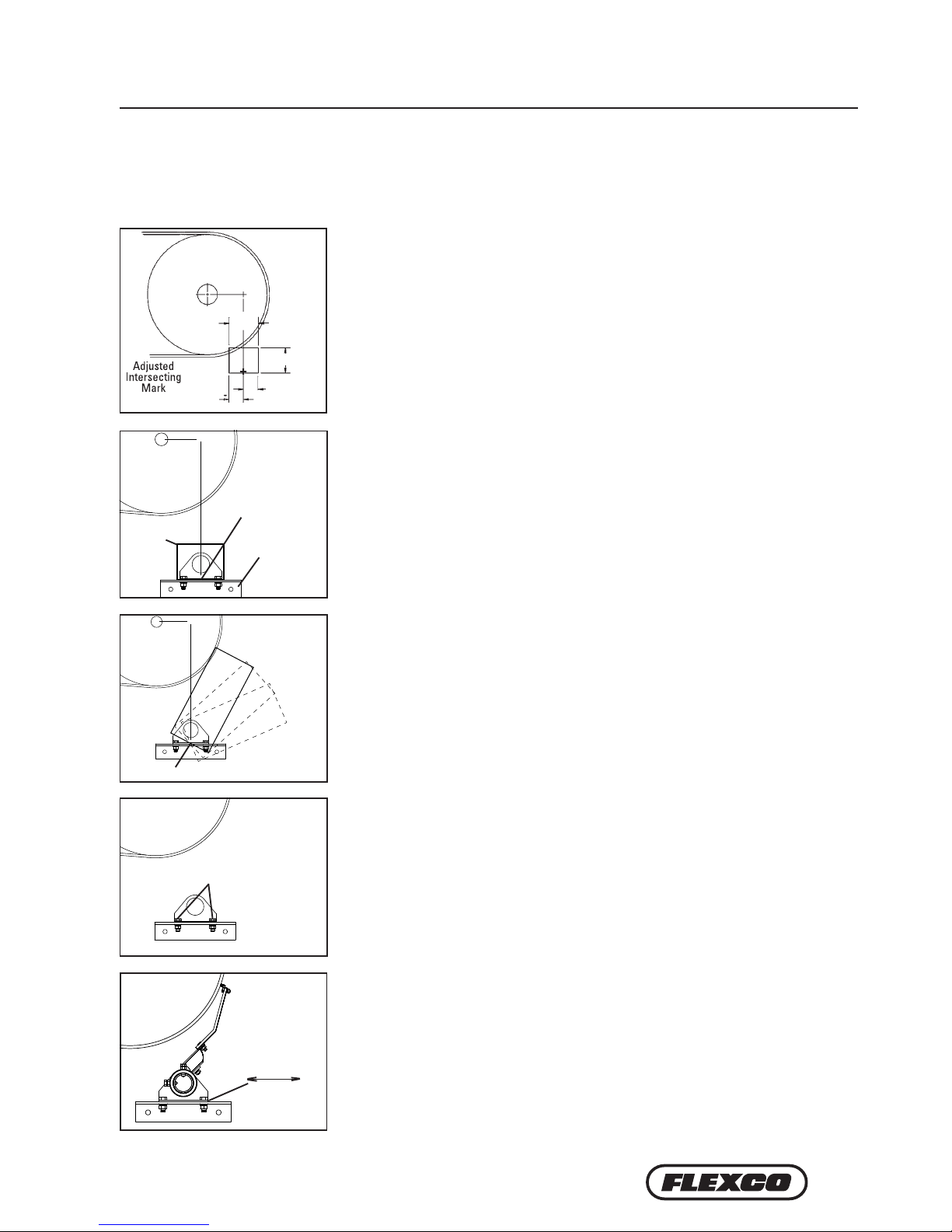
Fig. 3
5. Cut chute opening. Using the adjusted intersecting mark (“+”) established in
Step 4, layout and cut the required opening 125x150mm on the chute (Fig. 3).
If access hole is required, see Step 7.
6. Install the mounting brackets. Centre the mounting bracket on the bottom of
the opening. Bolt or weld in position (Fig 4). Repeat process on opposite side.
7. Cutting the access hole. Cut access hole, centreing the bottom edge on the
adjusted intersecting mark (“+”) established in Step 4. Width of hole should be
175mm; height should be 325mm for extra small arms, 375mm for small arms,
420mm for medium arms, 450mm for large arms or 555mm for extra large
arms. Access hole may be oriented within the range shown (Fig. 5), provided
bottom edge is still centreed as described above.
Slide
Fig. 7
9. Position the pole. Rotate pole upward to bring tips into contact with head
pulley (Fig. 7). Centre the tips across the belt. While applying light pressure
on the centre tip, shi loosened bearing mount until tips are contacting belt
evenly across full width. Lock cleaner into this position by tightening
bearing mount bolts.
For step-by-step instructions on installing the spring tensioner, refer to page 13.
Bearing Mount Bolts
8. Install the pole. Remove the two bearing mount bolts from one of the
bearing mounts (Fig. 6). (If chute mount, remove from the side with access
hole.) Slide the pole across the pulley and into the bearing mount on other
side and allow tips to hang down. Install the removed bearing mount on
the pole and reattach to the mounting bracket. Do not tighten; leave nger
tight.
150mm
125mm
Chute Mounting (cont.)
75mm
75mm
+ +
+
Chute
Opening
Adjusted
intersecting
mark
Mounting
Bracket
Fig. 4
Fig. 5
Adjusted Intersecting Mark
Fig. 6
Page 10
10 H-Type® Primary Cleaner with V-Tips
4.2b H-Type© Primary Cleaner with V-Tips
Section 4 – Installation Instructions
Fig. 2
Fig. 3
a) shaft to structure ________
b) pulley shaft diameter ________ ÷ 2 ________
+
c) pulley shaft centre line to structure = ________
d) add X measurement from chart ________
+
centre of pole from structure = ________
e) add 175mm (half length of
mounting bracket) 175mm
+
length of support material needed = ________
3. Locate X location.
a.) Measure from the back of the pulley shaft to the support structure (Fig. 3).
b.) Pulley shaft diameter divided by 2.
c.) Add dimensions from a) and b). This dimension is the pulley shaft centreline to the support structure.
d.) Add the given X dimension to c). The sum indicates the distance from the centre of the pole to the support
structure.
e.) Add 175mm (half the length of the mounting bracket). The sum is the total length of support material needed
to correctly locate the mounting brackets.
4. Secure mounting support pieces to the support structure. Weld support pieces to the support structure.
75x75mm angle works well for these support pieces.
5. Prepare the support pieces for the cleaner mounting brackets. Clamp the mounting bracket on the support
piece. Mark and drill holes for mounting or weld.
1. Find X and Y measurements. Find the X and Y measurement
specifications for the pulley diameter. See charts on pages 12 and 13.
The pulley diameter measurement should include lagging and belt.
Pulley Diameter________mm X________mm Y________mm
Using the correct X and Y coordinates will position the cleaner at 15°
below the horizontal plane on the head pulley.
2a. Locate Y location. Determine the diameter of the pulley shaft and
divide by 2.
2b. Put a level on top of the pulley shaft and mark A at the structure.
Measure down from Mark A half the diameter of the pulley shaft and
mark B, locating the shaft centreline (Fig. 1).
2c. Measure down the given Y dimension plus 70mm and mark (Fig. 2).
This mark indicates the top location of support material to be added for
installing the cleaner mounting brackets.
Open Head Mounting
Fig. 1
Mark "B"
Mark "A"
Belt Direction
Mark
Mark "B"
Y + 70mm
c+d+e
Length of
support
material
needed
Support structure
b
a
Page 11
11
4.2b H-Type© Primary Cleaner with V-Tips
Section 4 – Installation Instructions
7. Position the pole. Rotate pole upward to bring tips into contact with
head pulley (Fig. 7). Centre the tips across the belt. While applying
light pressure on the centre tip, shift loosened bearing mount until
tips are contacting belt evenly across full width. Lock cleaner into
this position by tightening bearing mount bolts.
6. Install the pole. Remove the two bearing mount bolts from one of
the bearing mounts (Fig. 6). (If chute mount, remove from the side
with access hole.) Slide the pole across the pulley and into the bearing
mount on other side and allow tips to hang down. Install the removed
bearing mount on the pole and reattach to the mounting bracket.
NOTE: Do not tighten; leave finger tight.
Fig. 7
4.3 H-Type© Primary Cleaner with V-Tips - Bolt Tensioner
Open Head Mounting (cont.)
Bearing
Mount Bolts
Fig. 6
Slide
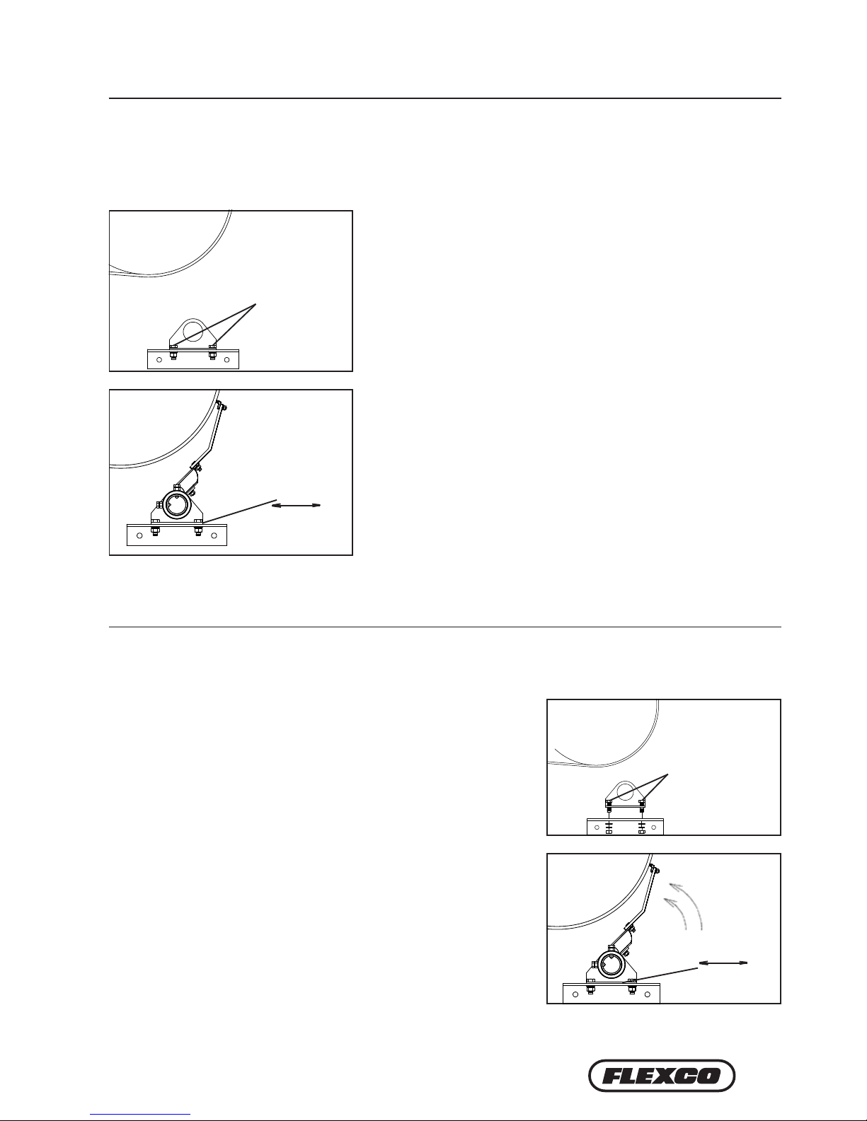
1. Install the pole. Remove the two bearing block bolts from
one of the bearing blocks (Fig. 1). (If chute mount, remove
from the side with access hole.) Slide the pole across the
pulley and into the bearing block on other side and allow tips
to hang down. Install the removed bearing block on the pole
and reattach to the mounting bracket. Do not tighten; leave
nger tight.
2. Position the pole. Rotate pole upward to bring tips into
contact with head pulley (Fig. 2). Centre the tips across
the belt. While applying light pressure on the centre tip,
shi loosened bearing block until tips are contacting belt
evenly across full width. Lock cleaner into this position by
tightening bearing mount bolts.
Fig. 2
Fig. 1
BEARING
BLOCK
BOLTS
Slide
Page 12

12 H-Type® Primary Cleaner with V-Tips
Section 4 – Installation Instructions
4.3 H-Type
©
Primary Cleaner with V-Tips - Bolt Tensioner
3. Install adjusting arms.
Note: If using optional spring tensioner, go to separate
instructions included in packet.
a. Screw adjusting bolts into the welded nut on each
mounting bracket (about 25mm above the mounting
bracket).
b. With pole rotated up, so that all tips contact the head
pulley, slide the adjusting arm onto pole, tight against
bearing block, resting on the adjusting bolt, pointed away
from the head pulley (Fig. 8). Tighten both adjusting arm
lock bolts and lock nuts (in the order shown in Fig. 3).
Repeat on opposite side.
4. Set tip tension.
Apply the following tension:
V-Tips -- 1-1/2 turns
Lock both adjusting bolt lock nuts (Fig. 4).
Fig. 3
Fig. 4
ADJUSTING ARM
LOCK BOLTS &
LOCK NUTS
ADJUSTING ARM
25mm
ADJUSTING
BOLT & LOCK NUT
5. Check for correct tip tension. Place a Tip Tension Gauge
between the tip and the belt on the centre tip (or tips) (Fig.
5). While pulling in a straight motion, read the tension
required to break contact between the tip and belt. 8kg is
recommended. Also check tension on both outer tips. Make
tension adjustments if needed.
6. Check tip alignment with gauge provided. Align the gauge
against the head pulley and move down until the gauge
contacts the top of the blade. e suspension arm should
align with lines marked on gauge (Fig. 6). If the alignment
is not correct, loosen both bearing block bolts and slide
pole to gain correct alignment. Correct one side at a time.
Tighten bolts and repeat Step 5.
7. Test run cleaner and inspect operation. If vibration occurs or more cleaning eciency is desired, increase tip
tension by making a 1/2 turn on each adjustment bolt.
Fig. 5
Fig. 6
Page 13

13
Section 4 – Installation Instructions
4.4 H-Type
©
Primary Cleaner with PCST Tensioner
1. Install the compression spring tensioner.
Remove the adjusting
nuts, bushings and spring from the pivot rod. Insert the pivot arm
through the slot in the torque arm. Slide the torque arm onto the
pole end (be sure the rotation of the arm is correct to tension the
blade).
4. Tension the blades to the belt. Rotate the blades until they
contact the belt. While holding the spring bushing flat on the
torque arm, rotate the torque arm until the pivot arm is against
the end of the slot nearest the pole. Tighten the locking bolts
and jam nuts on the torque arm (Fig. 3). NOTE: The torque arm
should be up against the mounting plate.
3. Verify your “C” dimension to insure the pole is in the correct position.
2. Reassemble the spring assembly. Slide the spring, washer and
bushings onto the pivot arm and turn the two adjusting nuts so
about 6mm of the pivot arm is exposed above the nuts (Fig. 2).
Pivot Arm
Torque Arm
Pivot
Shaft
Bracket
Mounting
Plate
Pole
Fig. 1
Fig. 2
Adjusting
Nuts
Washer
Bushings
Spring
Pivot
Arm
Fig. 3
Pivot Arm against slot
end nearest the pole
Tighten
locking
bolts and
jam nuts
Page 14

14 H-Type® Primary Cleaner with V-Tips
Section 4 – Installation Instructions
4.4 H-Type
©
Primary Cleaner with PCST Tensioner
5. Set the correct blade tension. Refer to the charts below for the spring length required
for the belt width. Lightly pull the pivot arm toward the end of the torque arm slot
nearest the pole and turn the adjusting nuts until the required spring length is achieved
(Fig. 4). Lock the top adjusting nut.
Test run the cleaner. Run the conveyor for at least 15 minutes and inspect the cleaning performance. Check the
spring length for proper tensioning. Make adjustments as necessary.
Pivot Arm
Top of
washer to
top of torque
arm
Adjusting
Nuts
Fig. 4
HV Black Spring Length Chart
Shaded are recommended
Belt Width SS S M L LL
600 112 111 110 109 107
800 110 109 107 107 104
1000 108 106 105 104 100
1200 106 104 102 101 97
1400 105 102 100 98 93
1600 103 100 97 96 90
1800 101 97 95 93 –
HV Gold Spring Length Chart
Shaded are recommended
Belt Width SS S M L LL
1400 - 108 106 106 103
1600 108 106 105 104 100
1800 107 105 103 102 98
2000 106 104 102 100 96
2200 105 102 100 99 94
2400 104 101 99 97 –
2600 102 99 97 95 –
2800 101 98 95 94 –
3000 100 97 94 – –
3200 99 95 92 – –
HV Silver Spring Length Chart
Shaded are recommended
Belt Width SS S M L LL
2200 – – 158 157 154
2400 – 158 157 156 152
2600 – 157 156 155 151
2800 – 156 155 154 150
3000 158 155 154 152 148
3200 157 155 153 151 147
Page 15

15
Section 4 – Installation Instructions
4.5 H-Type
©
Primary Cleaner with PCST Tensioner - Bolt Tension
1. Install the pole. Remove the two bearing block bolts from
one of the bearing blocks (Fig. 1). (If chute mount, remove
from the side with access hole.) Slide the pole across the
pulley and into the bearing block on other side and allow tips
to hang down. Install the removed bearing block on the pole
and reattach to the mounting bracket. Do not tighten; leave
nger tight.
2. Position the pole. Rotate pole upward to bring tips into
contact with head pulley (Fig. 2). Centre the tips across
the belt. While applying light pressure on the centre tip,
shi loosened bearing block until tips are contacting belt
evenly across full width. Lock cleaner into this position by
tightening bearing mount bolts.
3. Install adjusting arms.
a. Screw adjusting bolts into the threaded mounting bracket
(about 25mm above the mounting bracket).
b. With pole rotated up, so that all tips contact the head
pulley, slide the adjusting arm onto pole, tight against
bearing block, resting on the adjusting bolt, pointed away
from the head pulley (Fig. 8). Tighten both adjusting arm
lock bolts and lock nuts (in the order shown in Fig. 3).
Repeat on opposite side.
4. Set tip tension.
Apply the following tension:
V-Tips — 1-1/2 turns
Lock both adjusting bolt lock nuts (Fig. 4).
Fig. 2
Fig. 3
Fig. 1
Slide
ADJUSTING ARM
LOCK BOLTS &
LOCK NUTS
ADJUSTING
ARM
BEARING
BLOCK
BOLTS
25mm
Fig. 4
ADJUSTING
BOLT &
LOCK NUT
Page 16

16 H-Type® Primary Cleaner with V-Tips
Section 4 – Installation Instructions
4.5 H-Type
©
Primary Cleaner with PCST Tensioner - Bolt Tension
5. Check for correct tip tension. Place a Tip Tension Gauge
between the tip and the belt on the centre tip (or tips) (Fig.
5). While pulling in a straight motion, read the tension
required to break contact between the tip and belt. 12kg is
recommended. Also check tension on both outer tips. Make
tension adjustments if needed.
6. Check tip alignment with gauge provided. Align the gauge
against the head pulley and move down until the gauge
contacts the top of the blade. e suspension arm should
align with lines marked on gauge (Fig. 6). If the alignment
is not correct, loosen both bearing block bolts and slide
pole to gain correct alignment. Correct one side at a time.
Tighten bolts and repeat Step 5.
7. Test run cleaner and inspect operation. If vibration occurs or more cleaning eciency is desired, increase tip
tension by making a 1/2 turn on each adjustment bolt.
Fig. 5
Fig. 6
Page 17

17
Section 5 – Cleaner Pole Location Charts
STEMSTEM
STEMSTEM
STEM
STEMSTEM
STEMSTEM
STEM
STEMSTEM
STEMSTEM
STEM
5.1 Pole Location Charts
Extra Small (SS) V-Arms
for Head Pulley Diameters
up to 499mm
Diameter
(Over Belt)
X Y C Gap
250 28 292 294 56
275 40 295 298 51
300 52 299 303 46
325 64 302 309 43
350 76 305 315 39
375 88 308 321 36
400 100 312 327 33
425 113 315 334 30
450 125 318 342 28
475 137 321 349 25
500 149 325 357 23
525 161 328 365 22
550 173 331 373 20
575 185 334 382 18
Small (S) V-Arms
for Head Pulley Diameters
500-799mm
Diameter
(Over Belt) X Y C Gap
350 50 361 365 78
375 62 365 370 73
400 74 368 375 68
425 86 371 381 64
450 98 374 387 60
475 110 377 393 56
500 122 381 400 52
525 134 384 407 49
550 146 387 414 46
575 158 390 421 43
600 171 394 429 40
625 183 397 437 38
650 195 400 445 36
675 207 403 453 33
700 219 407 462 31
725 231 410 470 29
750 243 413 479 27
775 255 416 488 26
800 267 420 497 24
825 279 423 507 23
850 291 426 516 21
875 303 429 526 20
900 315 432 535 18
Page 18

18 H-Type® Primary Cleaner with V-Tips
Section 5 – Cleaner Pole Location Charts
STEMSTEM
STEMSTEM
STEM
Medium (M) V-Arms
for Head Pulley Diameters
800-999mm
Diameter
(Over Belt) X Y C Gap
650 180 445 480 63
675 192 449 488 60
700 204 452 496 57
725 216 455 504 54
750 228 458 512 54
775 240 462 520 50
800 252 465 529 47
825 264 468 538 45
850 277 471 546 43
875 289 475 555 41
900 301 478 565 39
925 313 481 574 37
950 325 484 583 36
975 337 487 593 34
1000 349 491 602 32
1025 361 494 612 31
1050 373 497 622 29
1075 385 500 632 28
1100 397 504 641 27
1125 409 507 652 26
5.1 Pole Location Charts (cont.)
Large (L) V-Arms
for Head Pulley Diameters
1000-1199mm
Diameter
(Over Belt) X Y C Gap
850 253 494 556 46
875 265 498 564 43
900 278 501 573 41
925 290 504 581 39
950 302 507 590 37
975 314 511 599 35
1000 326 514 608 33
1025 338 517 618 31
1050 350 520 627 29
1075 362 524 637 27
1100 374 527 646 26
1125 386 530 656 24
1150 398 533 666 22
1175 410 537 675 21
1200 422 540 685 20
STEMSTEM
STEMSTEM
STEM
STEMSTEM
STEMSTEM
STEM
STEMSTEM
STEMSTEM
STEM
Page 19

19
Section 5 – Cleaner Pole Location Charts
5.1 Pole Location Charts (cont.)
Extra Large (XL) V-Arms
for Head Pulley Diameters
1200-1700mm
Diameter
(Over Belt) X Y C Gap
1200 414 650 771 79
1225 426 653 780 76
1250 438 657 789 74
1275 450 660 799 72
1300 462 663 808 70
1325 474 666 818 68
1350 486 670 827 66
1375 498 673 837 64
1400 510 676 847 62
1425 522 679 857 60
1450 534 683 867 59
1475 546 686 877 57
1500 558 689 887 55
1525 570 692 897 54
1550 583 695 907 52
1575 595 699 917 51
1600 607 702 928 49
1625 619 705 938 48
1650 631 708 949 47
1675 643 712 959 45
1700 655 715 970 44
STEMSTEM
STEMSTEM
STEM
STEMSTEM
STEMSTEM
STEM
Page 20

20 H-Type® Primary Cleaner with V-Tips
• Recheck that all fasteners are tightened properly.
• Add pole caps.
• Apply all supplied labels to the cleaner .
• Check the blade location on the belt.
• Be sure that all installation materials and tools have been removed from the belt and the conveyor area.
6.2 Test Run the Conveyor
• Run the conveyor for at least 15 minutes and inspect the cleaning performance.
• Check the tensioner spring for recommended length (proper tensioning).
• Make adjustments as necessary.
NOTE: Observing the cleaner when it is running and performing properly will help to detect problems or
when adjustments are needed later.
6.1 Pre-Op Checklist
Section 6 – Pre-Operation Checklist and Testing
Page 21

21
Section 7 – Maintenance
Flexco belt cleaners are designed to operate with minimum maintenance. However, to maintain superior performance
some service is required. When the cleaner is installed a regular maintenance program should be set up. This program
will ensure that the cleaner operates at optimal efficiency and problems can be identified and fixed before the cleaner
stops working.
All safety procedures for inspection of equipment (stationary or operating) must be observed. The H-Type® Primary
Cleaner operates at the discharge end of the conveyor and is in direct contact with the moving belt. Only visual
observations can be made while the belt is running. Service tasks can be done only with the conveyor stopped and by
observing the correct lockout/tagout procedures.
7.1 New Installation Inspection
After the new cleaner has run for a few days a visual inspection should be made to ensure the cleaner is
performing properly. Make adjustments as needed.
7.2 Routine Visual Inspection (every 2-4 weeks)
A visual inspection of the cleaner and belt can determine:
• If the spring length is the correct length for optimal tensioning.
• If the belt looks clean or if there are areas that are dirty.
• If the blade is worn out and needs to be replaced.
• If there is damage to the blade or other cleaner components.
• If fugitive material is built up on the cleaner or in the transfer area.
• If there is cover damage to the belt.
• If there is vibration or bouncing of the cleaner on the belt.
• If a snub pulley is used, a check should be made for material buildup on the pulley.
If any of the above conditions exist, a determination should be made on when the conveyor can be stopped
for cleaner maintenance.
7.3 Routine Physical Inspection (every 6-8 weeks)
When the conveyor is not in operation and properly locked and tagged out a physical inspection of the cleaner
to perform the following tasks:
• Clean material buildup off the cleaner blade and pole.
• Closely inspect the blade for wear and any damage. Replace if needed.
• Check both blade pins for proper installation and condition. Replace if needed.
• Ensure full blade to belt contact.
• Inspect the cleaner pole for damage.
• Inspect all fasteners for tightness and wear. Tighten or replace as needed.
• Replace any worn or damaged components.
• Check the tension of the cleaner blade to the belt. Adjust the tension if necessary.
• When maintenance tasks are completed, test run the conveyor to ensure the cleaner is performing
prop e rl y.
Page 22

22 H-Type® Primary Cleaner with V-Tips
7.4 Blade Replacement Instructions
Section 7 – Maintenance
Tools Needed
• Tape measure
• (2) 38mm wrenches or crescent wrenches
• (1) 17mm wrench
• Wire brush (for cleaning pole)
• Small putty knife (for cleaning pole)
1. Remove the tension. Loosen the adjusting nuts on the mounting
bracket/PCST assembly to remove tension from the arm (Fig. 1). This
releases the tension of the blade on the belt.
2. Remove the worn tips. Remove the nuts on each tip and remove the
tips from the cushion (Fig. 2). Clean all fugitive material from the pole.
NOTE: If tips are hard to remove use a screwdriver or hammer to
loosen it and then remove.
Physically lock out and tag the conveyor at the power source
before you begin cleaner installation.
Fig. 1
Fig. 2
V-Tip
Mounting Nuts
Nuts, lock
washers and
flat washers
Remove
Adjusting nuts
Page 23

23
7.4 Blade Replacement Instructions (cont.)
Section 7 – Maintenance
Test run the cleaner. Run the conveyor for at least 15 minutes
and inspect the cleaning performance. Check the spring length
for proper tensioning. Make adjustments as necessary.
3. Install the new tips. Locate each tip onto each suspension arm,
then install the hardware to fasten the tip to the suspension
arm (Fig. 3).
Fig. 3
Page 24

24 H-Type® Primary Cleaner with V-Tips
7.5 Maintenance Log
Section 7 – Maintenance
Conveyor Name/No. _________________________
Date: ___________________ Work done by: ___________________ Service Quote #: ___________________
Activity: _____________________________________________________________________________________
_____________________
Date: ___________________ Work done by: ___________________ Service Quote #: ___________________
Activity: _____________________________________________________________________________________
_____________________
Date: ___________________ Work done by: ___________________ Service Quote #: ___________________
Activity: _____________________________________________________________________________________
_____________________
Date: ___________________ Work done by: ___________________ Service Quote #: ___________________
Activity: _____________________________________________________________________________________
_____________________
Date: ___________________ Work done by: ___________________ Service Quote #: ___________________
Activity: _____________________________________________________________________________________
_____________________
Date: ___________________ Work done by: ___________________ Service Quote #: ___________________
Activity: _____________________________________________________________________________________
_____________________
Date: ___________________ Work done by: ___________________ Service Quote #: ___________________
Activity: _____________________________________________________________________________________
_____________________
Page 25

25
7.6 Cleaner Maintenance Checklist
Section 7 – Maintenance
Site: _____________________________ Inspected by: ______________________________ Date: _____________________________
Belt Cleaner: _____________________________________________ Serial Number: _________________________________________
Beltline Information:
Beltline Number: ____________________ Belt Condition: _______________________________________________________________
Belt Width: ¨ 450mm ¨ 600mm ¨ 750mm ¨ 900mm ¨ 1050mm ¨ 1200mm ¨ 1350mm ¨ 1500mm ¨ 1800mm
(18") (24") (30") (36") (42") (48") (54") (60") (72")
Head Pulley Diameter (Belt & Lagging):__________ Belt Speed:________ fpm Belt Thickness: __________
Belt Splice:__________ Condition of Splice:_________ Number of Splices:________ ¨ Skived ¨ Unskived
Material conveyed: ________________________________________________________________________________________________
Days per week run:_______________ Hours per day run:_______________
Blade Life:
Date blade installed:___________ Date blade inspected:___________ Estimated blade life:____________
Is blade making complete contact with belt? ¨ Yes ¨ No
Blade wear: Left _________ Middle _________ Right _________
Blade condition: ¨ Good ¨ Grooved ¨ Smiled ¨ Not contacting belt ¨ Damaged
Measurement of spring: Required _________ Currently _________
Was Cleaner Adjusted: ¨ Yes ¨ No
Pole Condition: ¨ Good ¨ Bent ¨ Worn
Lagging: ¨ Side Lag ¨ Ceramic ¨ Rubber ¨ Other ¨ None
Condition of lagging: ¨ Good ¨ Bad ¨ Other
Cleaner's Overall Performance: (Rate the following 1 - 5, 1= very poor - 5 = very good)
Appearance: ¨ Comments: ____________________________________________________________________________________
Location: ¨ Comments: ____________________________________________________________________________________
Maintenance: ¨ Comments: ____________________________________________________________________________________
Performance: ¨ Comments: ____________________________________________________________________________________
Other comments __________________________________________________________________________________________________
________________________________________________________________________________________________________________
________________________________________________________________________________________________________________
________________________________________________________________________________________________________________
________________________________________________________________________________________________________________
________________________________________________________________________________________________________________
Page 26

26 H-Type® Primary Cleaner with V-Tips
Section 8 – Troubleshooting
Problem Possible Cause Possible Solutions
Poor cleaning
performance
Cleaner under-tensioned Adjust to correct tension – see spring length chart
Cleaner over-tensioned Adjust to correct tension – see spring length chart
Cleaner installed in wrong location Verify "C" dimension, relocate to correct dimension
Cleaner blade worn or damaged Replace cleaner blade
Rapid Blade Wear
Tension on cleaner too high/low Adjust to correct tension – see spring length chart
Cleaner not located correctly Check cleaner location for correct dimensions
Blade attack angle incorrect Check cleaner location for correct dimensions
Material too abrasive for blade Option: switch to alternate cleaner with metal blades
Mechanical splice damaging blade Repair, skive or replace splice
Centre wear on blade
(smile eect)
Blade wider than material path Replace blade with width to match material path
Tension on cleaner too high/low Adjust to correct tension – see spring length chart
Unusual wear or
damage to blade
Mechanical splice damaging blade Repair, skive or replace splice
Belt damaged or ripped Repair or replace belt
Cleaner not correctly located Verify "C" dimension, relocate to correct dimension
Damage to pulley or pulley lagging Repair or replace pulley
Vibration or noise
Cleaner not located correctly Verify "C" dimension, relocate to correct dimension
Blade attack angle incorrect Verify "C" dimension, relocate to correct dimension
Cleaner running on empty belt Use a spray pole when the belt is empty
Cleaner tension too high/low Adjust to correct tension or slight adjust to diminish
Cleaner locking bolts not secure Check and tighten all bolts and nuts
Cleaner not square to head pulley Verify "C" dimension, relocate to correct dimension
Material buildup in chute Clean up build-up on cleaner and in chute
Cleaner being pushed
away from pulley
Cleaner tension not set correctly Ensure correct tension/increase tension slightly
Sticky material is overburdening cleaner
Increase tension; replace with cleaner with metal tips;
replace with larger size cleaner
Cleaner not set up correctly Conrm location dimensions are equal on both sides
Page 27

27
Section 9 – Specs and CAD Drawings
Overall Pole Length
Maximum Conveyor Span
Pole Length Specifications*
Cleaner Size Pole Length
Maximum
Conveyor Span
mm in. mm in. mm in.
450 18 1650 66 1400 56
600 24 1800 72 1550 62
750 30 1950 78 1700 68
900 36 2100 84 1850 74
1050 42 2250 90 2000 80
1200 48 2400 96 2150 86
Pole Diameter - 60mm (2-3/5")
Clearance Guidelines for Installation
Suspension
Arm Size
Horizontal
Clearance
Required
Vertical
Clearance
Required
mm in. mm in.
SS 175 7 325 12 13/16
S 175 7 375 14 3/4
M 175 7 420 16 9/16
L 175 7 450 17 3/4
LL 175 7 555 21 7/8
Specifications:
• Maximum Belt Speed ............................ 5M/sec
• Temperature Rating ............................... -35°C to 204°C
• Usable Blade Wear Length .................... 9mm
• Blade Material......................................... Long Life Tungsten Carbide (for vulcanized belts only)
• Available for Belt Widths ...................... 450 to 1200mm.
Other sizes available upon request.
* CEMA Cleaner Rating .......................... Class 4
9.1 Specications and Guidelines
VERTICAL
HORIZONTAL
Page 28

28 H-Type® Primary Cleaner with V-Tips
Section 9 – Specs and CAD Drawings
9.2 CAD Drawing - Primary Cleaner with V-Tips for Belts up to 1600mm
4
1
4
1
5
°
C
HU
TE
C
UTO
U
T '
M
'
N
=
1
75
2
7
7
5
23
3
3
6
3
8
4
BELT DIRECTION
ADD 6.5mm TO SUSPENSION ARM LENGTH FOR 73mm DIA POLES
HV-L
6
0.3
INSTALLATION
CUT OUT
45
75
260
18
40
350
62.5
FOR
60 POLE
70 FOR
73 POLE
HV-SS
6
0.3
IMPORTANT NOTE:
REFER INSTALLATION GUIDE FOR DIMENSIONS 'X' AND 'Y'.THESE
DIMENSIONS ARE DEPENDANT ON BELT THICKNESS AND PULLEYDIAMETER.
THE CLEANER IS DESIGNED TO PERFORM CORRECTLY WHEN THE
TIP MEETS THE BELT AT 90
, 15
DOWN FROM THE CENTRELINE OF THE PULLEY.
REFER TO INSTALLATION MANUAL.
POLE LENGTH 'A'
TIP WIDTH 'B'
199.50
HV-LL
6
0.3
HV-S
6
0.3
HV-M
6
0.3
TIP/ARM
M N SIZE
UP TO 499 325 SS
500 - 799 375 S
800 - 999 420 M
1000 -1199 450 L
1200 -1700 555 LL
175
O/A PULLEY
DIA.
CHUTE CUTOUT
BELT
WIDTH ORDER NO. ITEM CODE ORDER NO. ITEM CODE
450 HV450SS 73026 HV450SS- SS 75293
HV450S 73028 HV450S-SS 75294
HV450M 73019 HV450M-SS 75295
600 HV600SS 73045 HV600SS- SS 75296
HV600S 73030 HV600S-SS 75297
HV600M 73173 HV600M-SS 75298
750 HV750SS 73053 HV750SS- SS 75299
HV750S 73032 HV750S-SS 75300
HV750M 73174 HV750M-SS 75301
900 HV900SS 73055 HV900SS- SS 75302
HV900S 73034 HV900S-SS 75303
HV900M 73175 HV900M-SS 75304
HV900L 73178 HV900L-SS 75305
1050 HV1050SS 73057 HV1050SS-SS 75306
HV1050S 73056 HV1050S-SS 75
307
HV1050M 73036 HV1050M-SS 75308
HV1050L 73179 HV1050L-SS 75309
1200 HV1200SS 73059 HV1200SS-SS 75310
HV1200S 73058 HV1200S-SS 75311
HV1200M 73038 HV1200M-SS 75312
HV1200L 73180 HV1200L-SS 75313
1500 HV1500S 74203 HV1500S-SS A2234
HV1500M 73177 HV1500M-SS 75314
HV1500L 73158 HV1500L-SS 75315
HV1500LL 73215 HV1500LL-SS 75316
1600 HV1600M 73637 HV1600M-SS 75317
HV1600L 73638 HV1600L-SS 75318
HV1600LL 73639 HV1600LL-SS 75319
.LTS .SDETAOC REDWOP
COMPLETE ASS'Y. COMPLETE ASS'Y.
Page 29

29
9.2 CAD Drawing - Primary Cleaner with V-Tips for Belts over 1800mm
Section 9 – Specs and CAD Drawings
3
4
2
2
8
2
3
9
0
4
2
0
C
HUTE
C
UTO
UT
'M
'
1
5
°
N
=
175
528
HVHD-S
HVHD-SS
7
3
HVHD-M
HVHD-L
IMPORTANT NOTE:
REFER INSTALLATION GUIDE FOR DIMENSIONS 'X' AND 'Y'.THESE
DIMENSIONS ARE DEPENDANT ON BELT THICKNESS AND PULLEYDIAMETER.
THE CLEANER IS DESIGNED TO PERFORM CORRECTLY WHEN THE
TIP MEETS THE BELT AT 90
, 15
DOWN FROM THE CENTRELINE OF THE PULLEY.
REFER TO INSTALLATION MANUAL.
POLE LENGTH 'A'
INSTALLATION
CUT OUT
BELT DIRECTION
1
8
40
350
260
110
45
75
HVHD-LL
TIP/ARM
M N S IZE
UP TO 499 325 SS
500 - 799 375 S
800 - 999 420 M
1000 -1199 450 L
1200 -1700 555 LL
175
O/A PULLEY
DIA.
CHUTE CUTOUT
1800 HV HD1800M 74602 HV HD1800M-S/S A1594
1800 HV HD1800L 74477 HV HD1800L-S/S A1595
1800 HV HD 1800LL 74478 HV HD 1800LL-S/S A1596
2100 HV HD 2000M 74539 HV HD 2000M-S/S A1597
2100 HV HD 2000L 74540 HV HD 2000L-S/S A1598
2100 HV HD 2000LL 74541 HV HD 2000LL-S/S A1599
2400 HV HD 2500M 74544 HV HD 2500M-S/S A1600
2400 HV HD 2500L 74545 HV HD 2500L-S/S A1601
2400 HV HD 2500LL 74546 HV HD 2500LL-S/S A1602
2600 HV HD 2600M A2396 HV HD 2600M-S/S A2462
2600 HV HD 2600L A2461 HV HD 2600L-S/S A2463
2600 HV HD 2600LL A2397 HV HD 2600LL-S/S
A2464
3000 HV HD 3000M 74591 HV HD 3000M-S/S A2465
3000 HV HD 3000L 74592 HV HD 3000L-S/S A2466
3000 HV HD 3000LL 74593 HV HD30500LL-S/S A2467
Powder Coated Stainless Steel
BELT WIDTH
(mm)
Ordering
Number
ITEM
CODE
Ordering Number
ITEM
CODE
Page 30

30 H-Type® Primary Cleaner with V-Tips
Section 9 – Specs and CAD Drawings
9.2 CAD Drawing - H-Type
©
Primary Cleaner with PCST Tensioner
Y
1
5
°
C
X
18 TYP.
40
260
3
3
5
110
75
N
M
380
350
POLE LENGTH 'A'
TIP WIDTH 'B'
BELT
WIDTH
AR
M
SIZE
MILD STEEL STAINLESS STEEL
ORDER NO.
ITEM
CODE
ORDER NO.
ITEM
CODE
450
SS HV450SS-PCST 63936 HV450SS-PCST-S/S 63978
S HV450S-PCST 63937 HV450S-PCST-S/S 63979
M HV450M-PCST 63938 HV450M-PCST-S/S 63980
600
SS HV600SS-PCST 63939 HV600SS-PCST-S/S 63981
S HV600S-PCST 63940 HV600S-PCST-S/S 63982
M HV600M-PCST 63941 HV600M-PCST-S/S 63983
750
SS HV750SS-PCST 63942 HV750SS-PCST-S/S 63984
S HV750S-PCST 63943 HV750S-PCST-S/S 63985
M HV750M-PCST 63944 HV750M-PCST-S/S 63986
900
SS HV900SS-PCST 63945 HV900SS-PCST-S/S 63987
S HV900S-PCST 63946 HV900S-PCST-S/S 63988
M HV900M-PCST 63947 HV900M-PCST-S/S 63989
L HV900L-PCST 63948 HV900L-PCST-S/S 63990
1050
SS HV1050SS-PCST 64045 HV1050SS-PCST-S/S 63991
S HV1050S-PCST 63950 HV1050S-PCST-S/S 63992
M HV1050M-PCST 63951 HV1050M-PCST-S/S 63993
L HV1050L-PCST 63952 HV1050L-PCST-S/S 63994
1200
SS HV1200SS-PCST 63953 HV1200SS-PCST-S/S 63995
S HV1200S-PCST 63954 HV1200S-PCST-S/S 63996
M HV1200M-PCST 63955 HV1200M-PCST-S/S 63997
L HV1200L-PCST 63956 HV1200L-PCST-S/S 63998
1500
M HV1500M-PCST 63957 HV1500M-PCST-S/S 63999
L HV1500L-PCST 63958 HV1500L-PCST-S/S 64000
LL HV1500LL-PCST 63959 HV1500LL-PCST-S/S 64001
1600
M HV1600M-PCST 63960 HV1600M-PCST-S/S 64002
L HV1600L-PCST 63961 HV1600L-PCST-S/S 64003
LL HV1600LL-PCST 63962 HV1600LL-PCST-S/S 64004
**FOR LARGER SIZES PLEASE CONTACT FLEXCO
Page 31

31
REPLACEMENT PARTS POWDER COATED
REF DESCRIPTION
BELT
WIDTH
POLE
LENGTH
ORDERING
NUMBER
ITEM
CODE
WT.
KGS.
1
H-Type Pole Standard60 mm Pole Diameter
450 1250 HP450 73027 10.0
600 1350 HP600 73029 11.0
750 1500 HP750 73031 13.0
900 1650 HP900 73033 15.0
1050 1800 HP1050 73035 20.0
1200 1950 HP1200 73037 22.0
H-Type Pole Standard73 mm Pole Diameter
1500 2350 HP1500 73066 24.0
1600 2450 HP1600 73739 27.0
H-Type Pole Heavy-Duty73 mm Pole Diameter
Braced and Gussetted
1800 2650 HPHD1800 74601 34.0
2000 2950 HPHD2000 74547 39.0
2400 3250 HPHD2400 74548 43.5
Section 10 – Replacement Parts List
STAINLESS STEEL
ORDERING
NUMBER
ITEM
CODE
HP450-S/S 75373
HP600-S/S 75374
HP750-S/S 75375
HP900-S/S 75376
HP1050-S/S 75377
HP1200-S/S 75378
HP1500-S/S 75379
HP1600-S/S 75380
HPHD1800-S/S A2063
HPHD2000-S/S A1783
HPHD2400-S/S A2958
4
V Tip
1
2
5
6
7
2
Cushion HSA 73486 2.0 HVC-S/S 73494
Heavy-Duty Cushion HSHD 73483 2.0 HSHS-S/S 76467
- H Polyshield (Not shown) HPS8 73050 1.0 HSTSS 74771
4 V-Tip HSA200 73489 0.5 HVT8-S/S 75419
HVPT-S/S 73631
SIDE MOUNTING ASSEMBLY COMPONENTS- TO SUIT 60 mm
5 H Mounting Bracket HDMRK 74582 2.0 HDMRK-S/S 76245
6 H Bearing HBRK 73068 1.5 HBRK-S/S 75422
7 H Adjusting Arm HARK 73069 1.5 HARK-S/S 75423
8 Torque Arm Kit ESTAK-EST 76406 2.0 ESTAK-EST-S/S 78849
9 Acme Pivot Rod Kit ACME-PRK 62496 1.5 ACME-PRK 62496
10 Spring Bush Kit - Black and Gold HCSSB-B/G 62589 0.1 HCSSB-B/G 62589
11 Pole Bearing Bush HCBB-60 62513 0.1 HCBB-60 62513
12 Acme Nut ACME-N 62591 0.1 ACME-N 62591
SIDE MOUNTING ASSEMBLY COMPONENTS- TO SUIT 73 mm
5 H Mounting Bracket HDMRK 74582 3.0 HDMRK-S/S 76245
6 H Bearing HBRKX 74549 2.0 HBRKX-S/S 76246
7 H Adjusting Arm HDARK 74550 2.0 HDARK-S/S 76247
8 Torque Arm Kit HCSTAK 62494 2.0 HCSTAK-S/S 62495
9 Acme Pivot Rod Kit ACME-PRK 62496 1.5 ACME-PRK 62496
10 Spring Bush Kit - Black and Gold HCSSB-B/G 62589 0.1 HCSSB-B/G 62589
10a Spring Bush Kit - Silver HCSSB-S 62590 0.1 HCSSB-S 62590
11 Pole Bearing Bush HCBB-73 62514 0.1 HCBB-73 62514
12 Acme Nut ACME-N 62591 0.1 ACME-N 62591
Shaded items are made to
order. Call for lead time.
8
9
10a
10
11
12
PCST Tensioner
Page 32

Page 33

Page 34

Page 35

35
Section 11 – Other Flexco Conveyor Products
Flexco provides many conveyor products that help your conveyors to run more efficiently and safely. These
components solve typical conveyor problems and improve productivity.
Here is a quick overview on just a few of them:
• Patented ConShear™ blade renews its cleaning edge as it wears
• Visual Tension Check™ for optimal blade tensioning and
simple retensioning
• Quick and easy one-pin blade replacement Material Path
Option™ for optimal cleaning and reduced maintenance
MHS SAC Secondary Cleaner
• Patented “pivot & tilt” design for superior training action
• Dual sensor rollers on each side to minimise belt damage
• Pivot point guaranteed not to freeze or seize up
• Available for topside and return side belts
• A belt cleaner for the tail pulley
• Exclusive blade design quickly spirals debris off the belt
• Economical and easy to service
• Available in vee or diagonal models
PT Max™ Belt Trainer
Belt Ploughs
• Long-wearing tungsten carbide blades for superior cleaning
efficiency
• Patented PowerFlex™ cushions, the proven design found on
our industry-leading MHS Secondary Cleaner
• Service Advantage Cartridge can be easily removed and
replaced, even in the dirtiest conditions
• Works with Flexco mechanical belt splices
• “Limited space” cleaners for tight conveyor applications
• Cleaners for severe, high heat applications
• A rubber fingered cleaner for chevron and raised rib belts
• Multiple cleaner styles in stainless steel for corrosive
applications
Flexco Specialty Belt Cleaners
Rockline® EZP1 Primary Cleaner
• Adjusting troughing angles for easy installation and
adjustability
• Long-wearing UHMW for sealing the load zone
• Offered in both Light & Medium duty designs to affordably fit
your application
Flexco Slider/Impact Beds
Page 36

The Flexco Vision
To become the leader in maximising
belt conveyor productivity for our customers worldwide
through superior service and innovation.
Flexco (Aust.) Pty. Ltd • 10 Solent Circuit • Baulkham Hills NSW 2153 • Australia
Tel: 612-8818-2000 • Fax: 612-8824-6333 • E-mail: salesau@flexco.com
Visit www.flexco.com for other Flexco locations and products.
©2016 Flexible Steel Lacing Company. 010/03/16. For reorder: X4377
 Loading...