

Page 1
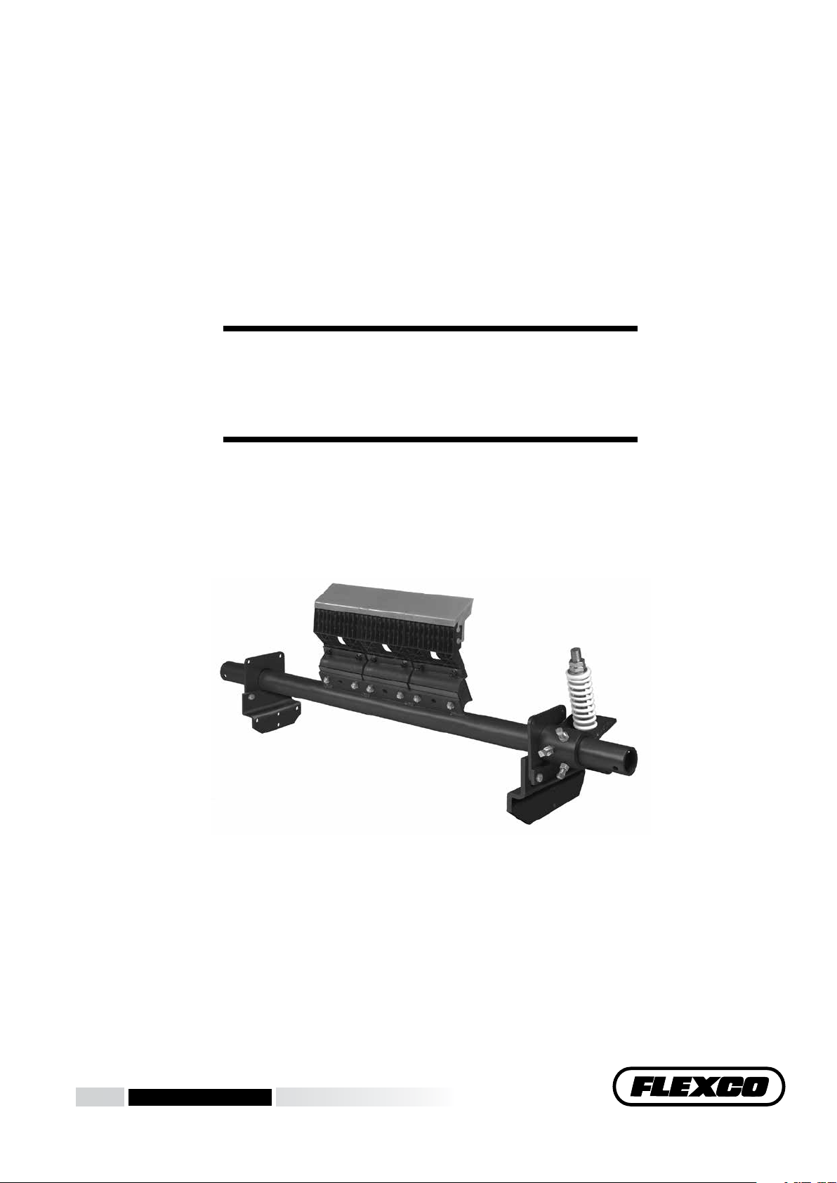
H-Type® Precleaner with XF2-Tips
Installation, Operation
and Maintenance Manual
www.flexco.com
www.flexco.com
Page 2

H-Type® Precleaner with XF2-Tips
Serial Number: _____________________________________________________________
Purchase Date: ______________________________________________________________
Purchased From: ____________________________________________________________
Installation Date: ____________________________________________________________
Serial number information can be found on the Serial Number Label
included in the Information Packet found in the cleaner carton.
This information will be helpful for any future inquiries or questions
about belt cleaner replacement parts, specifications or troubleshooting.
2 H-Type® Precleaner with XF2-Tips
Page 3

Table of Contents
Section 1 – Important Information ........................................................................................................................ 2
1.1 General Introduction ................................................................................................................................................ 2
1.2 User Benefits .............................................................................................................................................................. 2
1.3 Service Option ........................................................................................................................................................... 2
Section 2 – Safety Considerations and Precautions ...............................................................................................3
2.1 Stationary Conveyors ................................................................................................................................................ 3
2.2 Operating Conveyors ................................................................................................................................................ 3
Section 3 – Pre-Installation Checks and Options ................................................................................................... 4
3.1 Checklist ..................................................................................................................................................................... 4
3.2 Cleaner Location Adjustments................................................................................................................................. 5
Section 4 – Installation Instructions.......................................................................................................................6
4.1 Installation Instructions ........................................................................................................................................... 6
4.2 Pole Location Charts ................................................................................................................................................. 9
Section 5 – Pre-Operation Checklist and Testing.................................................................................................10
5.1 Pre-Op Checklist ..................................................................................................................................................... 10
5.2 Test Run the Conveyor ............................................................................................................................................ 10
Section 6 – Maintenance .......................................................................................................................................11
6.1 New Installation Inspection ................................................................................................................................... 11
6.2 Routine Visual Inspection ...................................................................................................................................... 11
6.3 Routine Physical Inspection ................................................................................................................................... 11
6.4 Blade Replacement Instructions ............................................................................................................................ 12
6.5 Maintenance Log ..................................................................................................................................................... 14
6.6 Cleaner Maintenance Checklist ............................................................................................................................. 15
Section 7 – Troubleshooting .................................................................................................................................16
Section 8 – Specs and CAD Drawings................................................................................................................... 17
8.1 Specifications and Guidelines ................................................................................................................................ 17
8.2 CAD Drawings......................................................................................................................................................... 18
Section 9 – Replacement Parts .............................................................................................................................. 22
Section 10 – Other Flexco® Conveyor Products .................................................................................................... 25
1
Page 4

Section 1 – Important Information
1.1 General Introduction
We at Flexco® are very pleased that you have selected an H-Type® Precleaner with XF2-Tips for your
conveyor system.
is manual will help you to understand the operation of this product and assist you in making it work
up to its maximum efficiency over its lifetime of service.
It is essential for safe and efficient operation that the information and guidelines presented be properly
understood and implemented. is manual will provide safety precautions, installation instructions,
maintenance procedures and troubleshooting tips.
If, however, you have any questions or problems that are not covered, please visit our web site or contact
our Customer Service Department:
Customer Service: 91-44-6551-7771
Visit www.flexco.com for other Flexco locations and products.
Please read this manual thoroughly and pass it on to any others who will be directly responsible for
installation, operation and maintenance of this cleaner. While we have tried to make the installation and
service tasks as easy and simple as possible, it does however require correct installation and regular
inspections and adjustments to maintain top working condition.
1.2 User Benets
Correct installation and regular maintenance will provide the following benefits for your operation:
• Reduced conveyor downtime
• Reduced man-hour labor
• Lower maintenance budget costs
• Increased service life for the belt cleaner and other conveyor components
1.3 Service Option
e H-Type® Precleaner with XF2-Tips is designed to be easily installed and serviced by your on-site
personnel. However, if you would prefer complete turn-key factory service, please contact your local
Flexco Field Representative.
2 H-Type® Precleaner with XF2-Tips
Page 5

Section 2 – Safety Considerations and Precautions
Before installing and operating the H-Type® Precleaner with XF2-Tips, it is important to review and understand the
following safety information.
There are set-up, maintenance and operational activities involving both stationary and operating conveyors. Each
case has a safety protocol.
2.1 Stationary Conveyors
The following activities are performed on stationary conveyors:
• Installation • Blade replacement • Repairs
• Tension adjustments • Cleaning
!
DANGER
!
WARNING
It is imperative that OSHA/MSHA Lockout/Tagout
(LOTO) regulations, 29 CFR 1910.147, be followed before
undertaking the preceding activities. Failure to use LOTO
exposes workers to uncontrolled behavior of the belt cleaner
caused by movement of the conveyor belt. Severe injury or
death can result.
Before working:
• Lockout/Tagout the conveyor power source
• Disengage any takeups
• Clear the conveyor belt or clamp securely in place
2.2 Operating Conveyors
There are two routine tasks that must be performed while the conveyor is running:
• Inspection of the cleaning performance
• Dynamic troubleshooting
DANGER
!
Use Personal Protective Equipment (PPE):
• Safety eyewear
• Hardhats
• Safety footwear
Close quarters, springs and heavy components
create a worksite that compromises a worker’s eyes,
feet and skull.
PPE must be worn to control the foreseeable
hazards associated with conveyor belt cleaners.
Serious injuries can be avoided.
!
WARNING
Every belt cleaner is an in-running nip hazard. Never
touch or prod an operating cleaner. Cleaner hazards
cause instantaneous amputation and entrapment.
!
WARNING
Belt cleaners can become projectile hazards. Stay as far
from the cleaner as practical and use safety eyewear and
headgear. Missiles can inflict serious injury.
Never adjust anything on an operating cleaner.
Unforseeable belt projections and tears can catch on
cleaners and cause violent movements of the cleaner
structure. Flailing hardware can cause serious injury
or death.
3
Page 6

Section 3 – Pre-installation Checks and Options
3.1 Checklist
• Check that the cleaner size is correct for the beltline width
• Check the belt cleaner carton and make sure all the parts are included
• Review the “Tools Needed” list on the top of the installation instructions
• Check the conveyor site:
- Will the cleaner be installed on a chute
- Is the install on an open head pulley requiring mounting structure
- Are there obstructions that may require cleaner location adjustments
4 H-Type® Precleaner with XF2-Tips
Page 7

Section 3 - Pre-Installation Checks and Options (cont.)
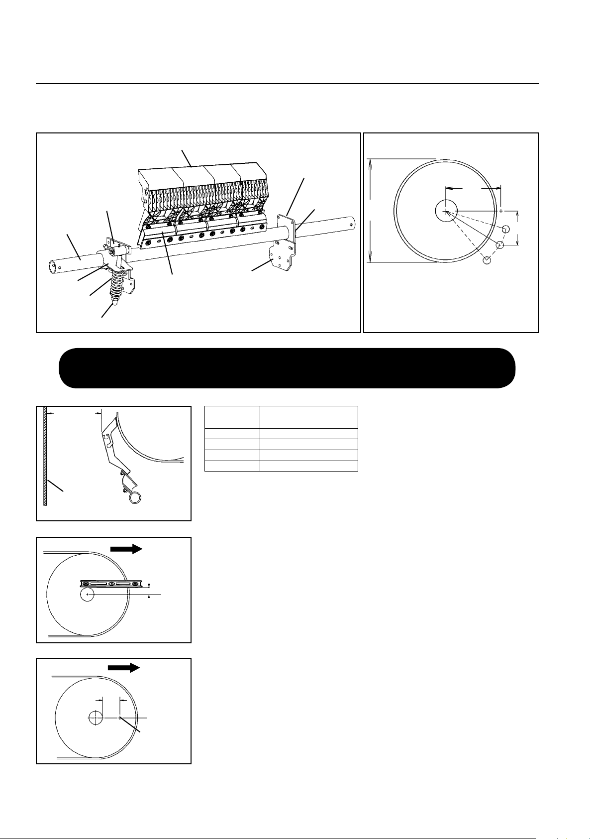
3.2 Cleaner Location Adjustments
In certain applications it is necessary to modify the location of the precleaner pole due to permanent obstacles that
obstruct the desired location. Relocating the pole location can be done easily and does not hinder the performance of the
cleaner as long as the “C” dimension is maintained.
NOTE: In the following example we will be lowering the pole location in the “Y” direction, but the same method
could also be applied in the “X” direction.
Conveyor situation:
Pulley Diameter: 900mm
X = 322mm
900mm
Y = 482mm
C = 580mm
1. Determine the given location dimensions and define the change needed. After laying out the given X & Y
dimensions, determine the distance of the modification required for adequate clearance of the pole and tensioning
system. (In the example we decide to lower the pole 50mm to clear the support structure).
X
C
Y
2. Write down known dimensions. We can now determine two of the three required dimensions which will allow us to
find the third. We know we cannot alter the “C” dimension, so this will remain the same. Also we are required to lower
the unit in the “Y” dimension 50mm, so we add 50mm to the given “Y” dimension.
X = ?"
Y = 482mm + 50mm = 532mm
C = 580mm
3. Determine final dimension. On a flat vertical surface, using a level, draw one horizontal line and one vertical line
creating a right triangle (Fig 3a). Measure down from the intersection the determined “Y” dimension and mark (Fig
3b). With the tape measure starting at the modified “Y” mark, swing the tape across the “X” line and mark at the “C”
dimension where it crosses the “X” line (Fig 3c). Measure from the intersection to the “C” intersection and this will be
your new “X” dimension (Fig. 3d).
X = 231mm
Y = 532mm
C = 580mm
This distance is
new “X” dimension
(231mm)
Y (532mm)
Fig. 3a Fig. 3b Fig. 3c Fig. 3d
mark
C (580mm)
5
Page 8
Section 4 – Installation Instructions
Pole Location Specs
For specific cleaner specs see charts on page 8
A
X
C
A = Pulley Diameter + Lagging and Belt
C = Critical Spec to move location if necessary
Y
Move Dim. C
on arc
Offset
Bracket
Xf2-Tip
Pole
Pivot Arm
Torque
Arm
HXF2 Parts List
Cushion
Tension
Spring
Mounting Plate
Pole Lock
Collar
(Hidden)
Pivot Shaft
Bracket
X
C
Y
Move Dim. C
on arc
X
C
Y
Move Dim. C
on arc
½ diameter of
pulley shaft
Belt Direction
“B”
“A”
Pole Location Specs
For specific cleaner specs see charts on page 8
A
X
C
A = Pulley Diameter + Lagging and Belt
C = Critical Spec to move location if necessary
Y
Move Dim. C
on arc
4.1 H-Type® Precleaner with HXF or HXF2 Tips
Xf2-Tip
Mounting Plate
Pole Lock
Pivot Shaft
Bracket
Collar
(Hidden)
X
A
Torque
Arm
Space needed to avoid clogging chute
Belt Direction
Belt Direction
Pole
Tension
Spring
Pivot Arm
Maximum
Maximum
lump size
lump size + 8”
(200mm)
+ 200mm (8")
Chute wall
Modified
Cushion
HXF2 Parts List
Offset
Bracket
A = Pulley Diameter + Lagging and Belt
C = Critical Spec to move location if necessary
Pole Location Specs
For specific cleaner specs see charts on page 8
Physically lock out and tag the conveyor at the power source
before you begin cleaner installation.
½ diameter of
pulley shaft
X
Intersecting
mark
“A”
“B”
“B”
Fig. 1
Fig. 2
HXF2
Blade Size
SS 250 - 475mm (10" - 19")
S 500 - 775mm (20" - 31")
M 800 - 975mm (32" - 39")
L 1000 - 1175mm (40" - 47")
Pulley Diameter
+ Belt and Lagging
Tools Needed:
• Tape measure
• Level
• Wrenches or Crescent Wrenches:
(1) M10 (17mm)
(2) M12 (19mm)
(1) M16 (24mm)
(2) M24 (36mm)
1. Find X, Y & C measurements. Find the X and Y measurement
specifications for the pulley diameter. See charts on page 8. The pulley
diameter measurement should include lagging and belt.
Pulley Diameter ________"; X=________"; Y=________"; C=________".
Using the correct X and Y coordinates will position the cleaner blades at
15° below the horizontal plane on the head pulley.
2. Measure head pulley shaft.
Determine the diameter of the pulley shaft
and divide by 2. ________"
3. Locate horizontal line from center of pulley shaft.
the pulley shaft and draw a horizontal line A. Measure down from Line
A half the diameter of the pulley shaft and draw Line B parallel from the
pulley shaft (Fig. 1).
4. Mark X dimension.
Subtract the above dimension (Step 2) from the
selected X dimension to establish the modified X dimension. With this
new X dimension measure horizontally from the front of the pulley shaft
forward on Line B and mark on the chute (Fig. 2).
C
Move Dim. C
on arc
Y
Put a level on top of
6 H-Type® Precleaner with XF2-Tips
Page 9
Section 4 – Installation Instructions
Offset
Bracket
Mounting
Plate
Chute wall
Offset
Bracket
Pulley
Chute wall
Side View
Align the
four template
notches with
location marks
Intersecting
mark
Y
X
Y
X
Align the
four template
notches with
location marks
Intersecting
mark
Y
X
Chute wall
Offset
Bracket
Pulley
Chute wall
Side View
Align the
four template
notches with
location marks
Intersecting
mark
Y
X
4.1 H-Type® Precleaner with HXF or HXF2 Tips (cont.)
Intersecting
Fig. 3
mark
Align the
four template
notches with
location marks
Fig. 4
Pulley
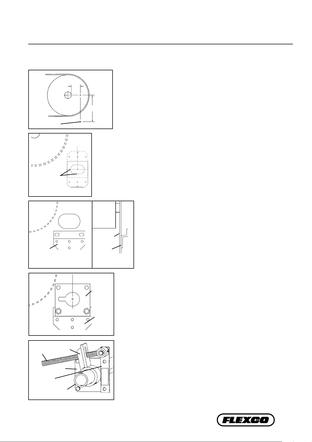
5. Determine Y dimension.
From the X mark, draw a line vertically down to the
selected Y dimension and make a mark (Fig. 3). This is the correct position for the
X
Y
center of the pole.
6. Locate offset bracket position. To locate the position of the offset bracket, position
offset bracket template with the large hole notches aligned with the layout lines on
the chute wall (Fig. 4). The template can be used with the bracket holes either below
or above the Y mark.
7. Cut pole opening. Using template provided, trace and cut the large opening and the
mounting holes.
8. Install offset brackets. Locate the offset brackets in the correct
position on the chute wall and bolt or weld in place (Fig. 5).
Pulley
9. Install the pole. Slide the pole across the pulley and through the
chute openings. Allow the tips to hang down.
Pivot Arm
Offset
Bracket
Fig. 5
Fig. 6
Pivot Shaft
Bracket
Fig. 7
Chute wall
Torque Arm
Mounting
Plate
Pole
Chute wall
Offset
Bracket
10. Install mounting plates. On one side, slide mounting plate onto
pole and with the key slot positioned horizontally and toward
the pulley, bolt to the offset bracket, center in slots and tighten
(Fig. 6). On opposite side repeat the process, but do not tighten.
Side View
11. Position the pole. Rotate the pole upward until the tips touch the belt.
Center the tips across the belt. While applying light pressure on the center
Mounting
Plate
tip, shift the loosened mounting plate until tips are contacting the belt
evenly across the full width. Lock cleaner into this position by tightening
mounting plate bolts.
Offset
Bracket
12. Center the cleaner on the belt and lock in place. Center the tips on the
belt and install a pole lock collar on one end of the pole. Slide the collar
snugly up to the mounting plate and tighten.
13. Install the QMT spring tensioner.
Remove the adjusting nuts, bushings
and spring from the pivot rod. Insert the pivot arm through the slot in the
torque arm. Slide the torque arm onto the pole end (be sure the rotation
of the arm is correct to tension the blade) and rotate it until the pivot shaft
bracket lines up with the desired bolt holes (Fig. 7). Remove bolts, nuts and
washers from mounting plate and reinsert through the pivot shaft bracket
and mounting plate.
7
Page 10

Pivot Arm
Bushings
Spring
Washer
Pivot Arm
Section 4 –
Installation Instructions
4.1 H-Type® Precleaner with HXF or HXF2 Tips (cont.)
Adjusting Nuts
Washer
Fig. 8
Pivot Arm against slot
end nearest the pole
Tighten locking
bolts and jam nuts
Fig. 9
Bushings
Spring
Pivot Arm
14. Reassemble the spring assembly. Slide the spring, washer and
bushings onto the pivot arm and turn the two adjusting nuts so
about 6mm (1/4") of the pivot arm is exposed above the nuts
(Fig.8).
15. Tension the blades to the belt. Rotate the blades until they contact
the belt. While holding the spring bushing flat on the torque arm,
rotate the torque arm until the pivot arm is against the end of the
slot nearest the pole. Tighten the locking bolts and jam nuts on the
torque arm (Fig. 9). NOTE: The torque arm should be up against
the mounting plate.
Adjusting
Nuts
Top of
washer to
top of torque
arm
Fig. 10
HXF2 Spring Length Chart
(for optimal blade tensioning)
Belt
Width Tips
450 2 114 102 145 N/A
600 3 142 138 135 N/A
750 3 142 138 135 N/A
900 4 127 130 5" 109
1050 5 128 120 152 152
1200 5 128 120 152 152
1350 6 120 152 149 149
1500 7 N/A 149 145 145
1800 8 N/A 145 142 142
Purple Spring
SS S M L
Spring Length
Silver Spring
White Spring
16. Set the correct blade tension. Refer to the chart on the pivot shaft bracket (also shown below) for the spring
length required for the belt width. Lightly pull the pivot arm toward the end of the torque arm slot nearest the pole
and turn the adjusting nuts until the required spring length is achieved (Fig. 10). Lock the top adjusting nut.
17. Verify your “C” dimension to insure the pole is in the correct position.
Test run the cleaner. Run the conveyor for at least 15 minutes and inspect the cleaning performance. Check the
spring length for proper tensioning. Make adjustments as necessary.
8 H-Type® Precleaner with XF2-Tips
Page 11

Section 4 –
Installation Instructions
4.2 Pole Location Charts
Extra Small (SS) XF2 Tips
for Head Pulley Diameters
250 - 475mm
Diameter
(Over Belt)
250 51 302 305 60
275 64 305 311 57
300 73 308 318 54
325 86 311 324 51
350 98 314 330 48
375 111 318 337 44
400 124 321 343 41
425 137 324 352 38
450 149 327 359 38
475 159 330 368 35
500 171 333 378 35
525 184 337 384 32
550 197 340 394 32
575 210 343 403 29
600 222 349 413 29
625 235 352 422 29
Recommended range for tip size
Optional extended range
X Y C Gap
Small (S) XF2 Tips
for Head Pulley Diameters
350 to 925mm
Diameter
(Over Belt) X Y C Gap
350 70 371 378 79
375 83 375 381 73
400 95 378 387 70
425 108 381 394 67
450 117 384 400 64
475 130 387 410 57
500 143 391 416 54
525 156 394 422 54
550 168 397 432 51
575 181 400 438 48
600 194 403 448 44
625 203 406 454 44
650 216 410 464 41
675 229 413 473 38
700 241 416 483 38
725 254 419 489 35
750 267 422 498 35
775 279 425 508 32
800 292 429 518 32
825 302 432 527 29
850 314 435 537 29
875 327 438 546 25
900 340 441 559 25
925 352 445 568 25
Medium (M) XF2 Tips
for Head Pulley Diameters
650 to 1125mm
Diameter
(Over Belt) X Y C Gap
650 206 451 495 64
675 219 454 505 60
700 232 457 511 57
725 244 460 521 57
750 254 464 530 54
775 267 467 540 51
800 279 470 549 51
825 292 473 556 48
850 305 476 565 44
875 318 479 575 44
900 330 483 584 41
925 343 486 594 41
950 352 492 603 38
975 365 495 616 38
1000 378 498 625 35
1025 391 502 635 35
1050 403 505 645 35
1075 416 508 654 32
1100 429 511 667 32
1125 438 514 676 32
Large (L) XF2 Tips
for Head Pulley Diameters
850 to 1325mm
Diameter
(Over Belt)
850 298 511 591 60
875 311 514 600 57
900 324 518 610 54
925 337 521 619 54
950 349 524 629 51
975 362 527 638 51
1000 375 530 648 48
1025 384 533 657 44
1050 397 537 667 44
1075 410 540 679 41
1100 422 543 689 41
1125 435 546 699 41
1150 448 549 708 38
1175 460 552 718 38
1200 473 556 730 35
1225 483 559 740 35
1250 495 562 749 35
1275 508 565 762 32
1300 521 568 772 32
1325 533 575 781 32
X Y C Gap
9
Page 12

Section 5 – Pre-Operation Checklist and Testing
5.1 Pre-Op Checklist
• Recheck that all fasteners are tightened properly
• Add pole caps
• Apply all supplied labels to the cleaner
• Check the blade location on the belt
• Be sure that all installation materials and tools have been removed from the belt and the conveyor area
5.2 Test Run the Conveyor
• Run the conveyor for at least 15 minutes and inspect the cleaning performance
• Check the tensioner spring for recommended length (proper tensioning)
• Make adjustments as necessary
NOTE: Observing the cleaner when it is running and performing properly will help to detect problems or
when adjustments are needed later.
10 H-Type® Precleaner with XF2-Tips
Page 13

Section 6 – Maintenance
Flexco® belt cleaners are designed to operate with minimum maintenance. However, to maintain superior
performance some service is required. When the cleaner is installed a regular maintenance program should be set
up. This program will ensure that the cleaner operates at optimal efficiency and problems can be identified and fixed
before the cleaner stops working.
All safety procedures for inspection of equipment (stationary or operating) must be observed. The H-Type®
Precleaner operates at the discharge end of the conveyor and is in direct contact with the moving belt. Only visual
observations can be made while the belt is running. Service tasks can be done only with the conveyor stopped and by
observing the correct lockout/tagout procedures.
6.1 New Installation Inspection
After the new cleaner has run for a few days a visual inspection should be made to ensure the cleaner is
performing properly. Make adjustments as needed.
6.2 Routine Visual Inspection (every 2-4 weeks)
A visual inspection of the cleaner and belt can determine:
• If the spring length is the correct length for optimal tensioning.
• If the belt looks clean or if there are areas that are dirty.
• If the blade is worn out and needs to be replaced.
• If there is damage to the blade or other cleaner components.
• If fugitive material is built up on the cleaner or in the transfer area.
• If there is cover damage to the belt.
• If there is vibration or bouncing of the cleaner on the belt.
• If a snub pulley is used, a check should be made for material buildup on the pulley.
If any of the above conditions exist, a determination should be made on when the conveyor can be stopped
for cleaner maintenance.
6.3 Routine Physical Inspection (every 6-8 weeks)
When the conveyor is not in operation and properly locked and tagged out a physical inspection of the
cleaner to perform the following tasks:
• Clean material buildup off of the cleaner blade and pole.
• Closely inspect the blade for wear and any damage. Replace if needed.
• Check both blade pins for proper installation and condition. Replace if needed.
• Ensure full blade to belt contact.
• Inspect the cleaner pole for damage.
• Inspect all fasteners for tightness and wear. Tighten or replace as needed.
• Replace any worn or damaged components.
• Check the tension of the cleaner blade to the belt. Adjust the tension if necessary using the chart on the
cleaner or the one on Page 7.
• When maintenance tasks are completed, test run the conveyor to ensure the cleaner is performing properly.
11
Page 14

Section 6 – Maintenance
6.4 Blade Replacement Instructions
XF2 Tip
Removal Nuts
H-Type® Precleaner with XF2-Tips
Physically lock out and tag the conveyor at the power source
before you begin cleaner installation.
Tools Needed:
• Tape measure
• (1) M10 (17mm) wrench or crescent wrench
• (2) M24 (36mm) wrenches or crescent wrenches
• Wire brush (for cleaning pole)
• Small putty knife (for cleaning pole)
1. Remove the tension. Loosen the adjusting nuts on both sides and
then turn them out until they are flush with the ends of the pivot
arms (Fig. 1). This releases the tension of the blade on the belt.
XF2 Replacement Tip
Pivot Arm
Adjusting Nuts
Fig. 1
2. Remove the worn tips. Remove the nuts on each tip and remove the
tips from the suspension arm (Fig. 2). Clean all fugitive material from
the pole.
NOTE: If tips are hard to remove use a screwdriver or hammer to
loosen it and then remove.
12 H-Type® Precleaner with XF2-Tips
Removal Nuts
Fig. 2
Page 15

Section 6 – Maintenance
6.4 Blade Replacement Instructions (cont.)
3. Install the new tips. Locate each tip onto each
suspension arm, then install the hardware to fasten
the tip to the cushion (Fig. 3).
4. Reset the correct blade tension. Refer to the chart for
the spring length required for the belt width. Lightly
pull the pivot arm toward the end of the torque arm
slot nearest the pole and turn the adjusting nuts until
the required spring length is achieved.
NOTE: The chart is also on the cleaner’s pivot shaft for
future reference for retensioning maintenance.
Fig. 3
Test run the cleaner. Run the
conveyor for at least 15 minutes
and inspect the cleaning
performance. Check the spring
length for proper tensioning.
Make adjustments as necessary.
Top of
washer
to top of
torque arm
HXF2 Spring Length Chart
(for optimal blade tensioning)
Belt
Width Tips
450 2 114 102 145 N/A
600 3 142 138 135 N/A
750 3 142 138 135 N/A
900 4 127 130 5" 109
1050 5 128 120 152 152
1200 5 128 120 152 152
1350 6 120 152 149 149
1500 7 N/A 149 145 145
1800 8 N/A 145 142 142
Purple Spring
SS S M L
Spring Length
Silver Spring
White Spring
13
Page 16

Section 6 – Maintenance
6.5 Maintenance Log
Conveyor Name/No.
Date: Work done by: Service Quote #
Activity:
Date: Work done by: Service Quote #
Activity:
Date: Work done by: Service Quote #
Activity:
Date: Work done by: Service Quote #
Activity:
Date: Work done by: Service Quote #
Activity:
Date: Work done by: Service Quote #
Activity:
Date: Work done by: Service Quote #
Activity:
14 H-Type® Precleaner with XF2-Tips
Page 17

Site: Inspected by: Date:
Belt Cleaner: Serial Number:
Beltline Information:
Beltline Number: Belt Condition:
Belt Width: 18" 24" 30" 36" 42" 48" 54" 60" 72"
Head Pulley Diameter (
Belt & Lagging)
: Belt Speed: fpm Belt Thickness:
Belt Splice Condition of Splice Number of splices Skived Unskived
Material conveyed
Days per week run Hours per day run
Blade Life:
Date blade installed: Date blade inspected:
Is blade making complete contact with belt? Yes No
Blade wear: LEFT MIDDLE RIGHT
Blade condition: Good Grooved Smiled Damaged
Measurement of spring: Required Currently
Was Cleaner Adjusted: Yes No
Pole Condition: Good Bent Worn
Lagging: Slide lag Ceramic Rubber Other None
Condition of lagging: Good Bad Other
Cleaner's Overall Performance:
( Rate the following 1 - 5, 1 = very poor - 5 = very good )
Appearance: Comments:
Location: Comments:
Maintenance: Comments:
Performance: Comments:
O
ther Comments:
Estimated blade life:
Not contacting belt
Section 6 – Maintenance
6.6 Cleaner Maintenance Checklist
15
Page 18

Section 7 – Troubleshooting
Problem Possible Cause Possible Solutions
Cleaner under-tensioned Adjust to correct tension – see spring length chart
Poor cleaning
performance
Rapid Blade Wear
Center wear on blade
(smile effect)
Unusual wear or
damage to blade
Cleaner over-tensioned Adjust to correct tension – see spring length chart
Cleaner installed in wrong location Verify "C" dimension, relocate to correct dimension
Cleaner blade worn or damaged Replace cleaner blade
Tension on cleaner too high/low Adjust to correct tension – see spring length chart
Cleaner not located correctly Check cleaner location for correct dimensions
Blade attack angle incorrect Check cleaner location for correct dimensions
Material too abrasive for blade Option: switch to alternate cleaner with metal blades
Mechanical splice damaging blade Repair, skive or replace splice
Blade wider than material path Replace blade with width to match material path
Tension on cleaner too high/low Adjust to correct tension – see spring length chart
Mechanical splice damaging blade Repair, skive or replace splice
Belt damaged or ripped Repair or replace belt
Cleaner not correctly located Verify "C" dimension, relocate to correct dimension
Vibration or noise
Cleaner being pushed
away from pulley
Damage to pulley or pulley lagging Repair or replace pulley
Cleaner not located correctly Verify "C" dimension, relocate to correct dimension
Blade attack angle incorrect Verify "C" dimension, relocate to correct dimension
Cleaner running on empty belt Use a spray pole when the belt is empty
Cleaner tension too high/low Adjust to correct tension or slight adjust to diminish
Cleaner locking bolts not secure Check and tighten all bolts and nuts
Cleaner not square to head pulley Verify "C" dimension, relocate to correct dimension
Material buildup in chute Clean up build-up on cleaner and in chute
Cleaner tension not set correctly Ensure correct tension/increase tension slightly
Sticky material is overburdening cleaner
Cleaner not set up correctly Confirm location dimensions are equal on both sides
Increase tension; replace with cleaner with metal tips;
replace with larger size cleaner
16 H-Type® Precleaner with XF2-Tips
Page 19

Section 8 – Specs and CAD Drawings
8.1 Specications and Guidelines
Pole Length Specifications*
Cleaner Size Pole Length
mm in. mm in. mm in.
450 18 1650 66 1400 56
600 24 1800 72 1550 62
750 30 1950 78 1700 68
900 36 2100 84 1850 74
1050 42 2250 90 2000 80
1200 48 2400 96 2150 86
1350 54 2550 102 2300 92
1500 60 2700 108 2450 98
1800 72 3000 120 2750 110
*For special extra long pole length requirements a Pole Extender Kit
(#76024) is available that provides 750mm (30") of extended pole length.
Pole Diameter - 73mm (2-7/8")
Clearance Guidelines
for Installation
Horizontal
Suspension
Arm Size
SS 175 7 325 13
S 175 7 375 15
M 175 7 413 16 1/2
L 175 7 463 18 1/2
LL 175 7 550 22
Clearance
Required
mm in. mm in.
Maximum
Conveyor Span
Vertical
Clearance
Required
Overall Pole Length
Maximum Conveyor Span
Vertical
Horizontal
HXF2 Spring Length Chart
(for optimal blade tensioning)
Belt
Width Tips
450 2 114 102 145 N/A
600 3 142 138 135 N/A
750 3 142 138 135 N/A
900 4 127 130 5" 109
1050 5 128 120 152 152
1200 5 128 120 152 152
1350 6 120 152 149 149
1500 7 N/A 149 145 145
1800 8 N/A 145 142 142
Purple Spring
SS S M L
Spring Length
Silver Spring
White Spring
Specifications:
• Maximum Belt Speed ..........................................5M/sec (1000 FPM)
• Temperature Rating .............................................-35°C to 82°CF (-30°F to 180°)
• Usable Blade Wear Length ..................................75mm (3")
• Blade Material ...................................................... Urethane (proprietary blend for
abrasion resistance and long wear)
• Available for Belt Widths .................................... 450mm to 1800mm (18" to 72").
Other sizes available upon request.
U.S. patent No. 6.926.133
Top of
washer
to top of
torque arm
17
Page 20

Section 8 – Specs and CAD Drawings
* OPTONAL EXTENDED RANGE
8.2 CAD Drawing - H-Type with XF2-Tips - SS
DIAMETER
OVER BELT
Y
C
GAP
X
11.01 [280]
POLE LOCATION CHART
GAP
C
Y
X
DIAMETER
(OVER BELT)
2-3/8
2-1/4
2-1/8
2
12-1/4
12-1/2
12-3/4
11-7/8 12
12-1/8
12-1/4
12
2-1/2
2-7/8
3-3/8
2
101214
13
11
1-3/8
1-3/4
1-5/8
1-1/2
1-1/2
1-7/8
13-1/4
13-1/2
13-7/8
14-1/2
14-1/8
13
13
12-5/8
12-3/4
12-1/2
12-7/8
12-3/8
4-7/8
5-3/8
4-3/8
6-1/4
5-7/8
3-7/8
19
171816
15
334
2
NO. OF
BLADES
"B"
15.75"
66"
72"
"A"
24"
18"
BELT
WIDTH
1-1/4
1-3/8
15-1/8
14-7/8
13-1/8
13-1/4
6-3/4
7-1/4
*20
*21
23.62"
31.45"
23.62"
78"
84"
36"
30"
1-1/8
1-1/8
1-1/4
15-7/8
15-1/2
16-1/4
13-3/48-3/4
13-1/2
13-3/8
8-1/4
7-3/4
*24
*23
*22
5
5
39.37"
39.37"
90"
96"
48"
42"
1-1/8
16-5/8
13-7/8
9-1/4
*25
6
47.25"
102"
54"
19.92 [506]
B
A
18 H-Type® Precleaner with XF2-Tips
76138
76139
CLEANER
76140
76141
76143
76142
76144
Page 21

Section 8 – Specs and CAD Drawings
* OPTIONAL EXTENDED RANGE
8.2 CAD Drawing - H-Type with XF2-Tips - S
DIAMETER
OVER BELT
Y
C
X
17.36°
GAP
22.092 [561.14]
11.028 [280.11]
POLE LOCATION CHART
DIAMETER
GAP
2-3/4
3-1/8
2-5/8
2-7/8
C
14-7/8
15-1/2
15
15-1/4
14-5/8
15
14-3/4
14-7/8
X Y
3-3/4
2-3/4
4-1/4
3-/1/4
*16
*17
*14
*1520*18
(OVER BELT)
2-1/421-7/8
2-1/8
2-1/8
2-1/2
16-1/815-1/4
16-3/8
16-5/8
15-3/4
17
15-3/8
15-1/2
15-1/8
15-5/8
6-5/8
5-1/8
5-5/8
6-1/8
4-5/8
*192223
21
1-3/4
17-1/4
17-5/8
15-3/4
15-7/8
7-1/8
7-5/8
24
1-1/2
1-3/4
1-5/8
18-5/8
18-1/4
17-7/8
16-1/4
16-1/8
16
9
8-1/2
8
26272825312930
1-1/2
1-3/8
19-1/4
19
16-3/8
16-1/2
9-1/2
10
1-3/8
1-1/4
19-5/816-5/8
20
16-3/4
10-1/2
11
1-1/8
1-1/8
1-1/4
20-3/4
21-1/8
20-3/8
17-1/8
17
16-7/8
11-7/8
12-3/8
11-1/2
*32
*33
*34
1
21-1/2
17-1/4
12-7/8
*35
1
1
22-3/8
22
17-1/2
17-3/8
13-7/8
13-3/8
*37
*36
5
5
3
4
2
B
NO. OF
BLADES
3
687
A
"B"
"A"
BELT
WIDTH
15.75"
66"
18"
76289
23.62"
31.50
23.62"
84"
72"
78"
30"
36"
24"
76293
76295
76291
39.38
39.38
90"
96"
42"
48"
76298
76301
55.09
47.22
102"
108"
60"
76145
76304 54"
62.96
120"
72"
76146
CLEANER
19
Page 22

Section 8 – Specs and CAD Drawings
* OPTIONAL EXTENDED RANGE
8.2 CAD Drawing - H-Type with XF2-Tips - M
DIAMETER
OVER BELT
Y
C
X
GAP
23.66 [601mm]
11.03 [280mm]
GAP
2-3/8
2-1/2
C
19-1/2
19-7/8
Y
17-7/8
17-3/4
X
8-5/8
8-1/8
POLE LOCATION CHART
*27
*26
DIAMETER
(OVER BELT)
2-1/4
2-1/4
20-1/2
20-1/8
18-1/8
18
9-5/8
9-1/8
*28
*29
2
2-1/8
2
20-7/8
21-1/4
21-5/8
18-1/211
18-3/8
18-1/4
10-1/2
10
32
*30
*31
1-3/4
1-7/8
1-3/4
21-7/8
22-1/4
22-5/8
18-5/8
18-7/8
18-3/4
11-1/2
12-1/2
12
353637
33
34
1-5/8
1-5/8
23-3/8
19-1/8
19 23
13-1/2
13
1-1/2
1-1/2
1-3/8
23-3/4
24-1/4
24-5/8
19-3/8
19-1/2
19-5/8
14-3/8
13-7/8
14-7/8
38
39
*40
1-3/8
1-3/8
25-3/8
25
19-3/4
19-7/8
15-3/8
15-7/8
*41
*42
1-1/4
1-1/4
1-1/4
25-3/4
26-5/8
26-1/4
2016-3/8
20-1/4
20-1/8
17-1/4
16-7/8
*44
*45
*43
B
20 H-Type® Precleaner with XF2-Tips
4
556
3
2
3
BLADES
NO. OF
A
"B"
15.75"
66"
"A"
18"
BELT
WIDTH
76290
CLEANER
31.50"
23.62"
23.62"
84"
72"
78"
30"
36"
24"
76296
76294
76292
39.38"
90"
42"
76299
7
39.38"
47.25"
55.12"
96"
108"
102"
48"
54"
60"
76302
76305
76307
8
63.00"
120"
76309 72"
Page 23

Section 8 – Specs and CAD Drawings
8.2 CAD Drawing - H-Type with XF2-Tips - L
DIAMETER
OVER BELT
Y
C
X
GAP
11.028 [280mm]
GAP
C
2-1/8
2-3/8
2-1/4
23-1/4
23-5/8
2420-3/8
2-1/822
24-3/4
25-1/8
24-3/8
1-3/4
1-7/8
25-1/2
25-7/8
1-3/4
1-5/8
26-1/4
26-3/4
1-5/8
1-5/8
27-1/2
27-1/8
1-1/2
1-1/2
1-3/8
27-7/8
28-1/4
28-3/4
1-3/8
1-3/8
29-1/2
29-1/8
1-1/4
1-1/4
30-3/8
30
1-1/4
30-3/4
25.004 [635mm]
2115-1/8
20-7/8
20-5/8
20-3/4
20-1/2
20-1/8
20-1/4
X Y
11-3/4
12-1/4
12-3/4
14-3/4
13-3/4
14-1/4
(OVER BELT)
*34
*35
13-1/4
*3640*39
*37
*38
41
POLE LOCATION CHART
DIAMETER
B
A
21-1/8
21-1/4
21-3/8
15-5/8
16-1/8
16-5/8
444543
42
NO. OF
21-5/8
21-1/2
17-1/8
17-5/8
46
BLADES
"B"
21-3/4
21-7/8
22
18-1/8
18-5/8
19
*49
*48
47
556
476297
39.38
22-1/4
22-1/8
19-1/2
20
*50
*51
39.38
47.25
22-3/8
20-1/2
21 22-5/8
*53
*52
8
7
55.12
63.00
* OPTIONAL EXTENDED RANGE
84" 31.50
"A"
36"
BELT
WIDTH
CLEANER
90"
96"
102"
42"
48"
54"
76300
76303
76306
120"
108"
60"
76310 72"
76308
21
Page 24

Section 9 – Replacement Parts
11
5
(hidden)
Replacement Parts
Ref Description
450mm (18") Pole H78P18 76110 41.2
600mm (24") Pole H78P24 76111 46.5
750mm (30") Pole H78P30 76112 50.3
900mm (36") Pole H78P36 76113 55.7
1
1050mm (42") Pole H78P42 76114 61.1
1200mm (48") Pole H78P48 76115 64.9
1350mm (54") Pole H78P54 76116 70.3
1500mm (60") Pole H78P60 76117 99.8
1800mm (72") Pole H78P72 76118 113.0
H2 XF Tip Cushion*
2a
(for S, M, L HXF2 Tips; or S-LL Susp. Arms)
H2 XF Tip Cushion, Neoprene* (oil resistant)
2b
(for S, M, L HXF2 Tips; or S-LL Susp. Arms)
H2 F Tip Cushion*
2c
(for SS HXF2 Tips; or SS Susp. Arms)
H2 F Tip Cushion, Neoprene* (oil resistant)
2d
(for SS HXF2 Tips; or SS Susp. Arms)
HXF2 Tip Extra Small* HXF2-SS 75979 3.0
HXF2 Tip Small* HXF2-S 75980 3.4
3
HXF2 Tip Medium* HXF2-M 75981 3.8
HXF2 Tip Large* HXF2-L 75982 4.1
5 Pole Lock Collar* (1 ea.) MSPPL 75816 1.9
6 Pivot Arm Kit* (1 ea.) QMTPAK 76096 4.3
7 Tension Spring - Purple (1 ea.)** QMTS-P 75845 0.6
7a Tension Spring - White (1 ea.)** PSTS-W 75898 1.7
7b Tension Spring - Silver (1 ea.)** PSTS-S 75899 3.0
8 Bushing Kit - Purple (2 ea.) (for Item 7) QMTBK-P 76097 0.1
8a Bushing Kit - White (2 ea.) (for Items 7a & 7b) QMTBK-W 76098 0.2
9 Pivot Shaft Bracket Kit* (1 ea.) QMTPSBK 76099 4.3
10 Torque Arm Kit* (1 ea.) PSTA 75896 11.4
11 Mounting Plate Kit* (2 ea.) MSPMPK 75811 8.3
12 Offset Bracket Kit* (1 ea.) HOBK 76399 12.4
QMT Spring Tensioner* - Purple
(incl. 1 ea. Items 6, 7, 8, 9, & 10)
QMT Spring Tensioner* - White
(incl. 1 ea. Items 6, 7a, 8a, 9, & 10)
QMT Spring Tensioner* - Silver
(incl. 1 ea. Items 6, 7b, 8a, 9, & 10)
*Hardware included
Note: All poles and tensioners are heavy duty style.
Parts for old style H cleaners.
Lead time: 1 working day
Number
HXFC2 75902 4.0
HXFC2SS 77044 4.0
HFC2 75901 4.0
HFC2SS 77043 4.0
QMT-P 76074 20.4
QMT-W 76075 21.8
VQMT-S 76402 23.9
Ordering
Item
Code
Wt.
Lbs.
3
2d
2c
2b
2a
1
HXF2
Spring Tensioner Selection Chart
Cleaner Type And Size
HXF2
450mm SS & S X
450mm M; 600mm 900mm;
1050mm 120mm SS & S; 1350mm SS
1050mm 1200mm M & L;
1350mm 1800mm S, M, L
76074
QMT-P
6
7
12
76075
QMT-W
X
9
8
7a
8a
7b
10
76402
QMT-S
X
22 H-Type® Precleaner with XF2-Tips
Page 25

Page 26

Page 27
Section 10 – Other Flexco® Conveyor Products
Flexco® provides many conveyor products that help your conveyors to run more efficiently and safely. These
components solve typical conveyor problems and improve productivity.
Here is a quick overview on just a few of them:
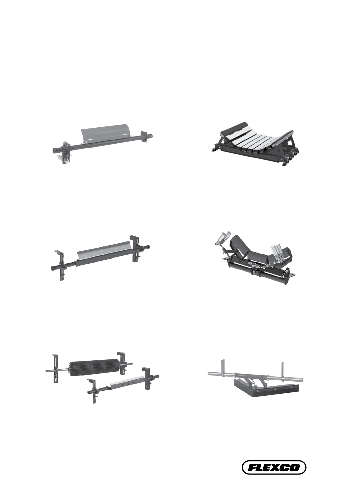
Rockline® EZP1 Precleaner
• Patented ConShear™ blade renews its cleaning edge as it wears
• Visual Tension Check™ for optimal blade tensioning and
simple retensioning
• Quick and easy one-pin blade replacement Material Path
Option™ for optimal cleaning and reduced maintenance
Rockline® EZS2 Secondary Cleaner
DRX™ Impact Beds
• Exclusive Velocity Reduction Technology™ to better protect
the belt
• Slide-Out Service™ gives direct access to all impact bars for
change-out
• Impact bar supports for longer bar life
• 4 models to custom fit to the application
PT Max™ Belt Trainer
• Long-wearing tungsten carbide blades for superior cleaning
efficiency
• Patented FormFlex™ cushions independently tension each
blade to the belt for consistent, constant cleaning power
• Easy to install, simple to service
• Works with Flexco mechanical belt splices
Flexco Specialty Belt Cleaners
• “Limited space” cleaners for tight conveyor applications
• High Temp cleaners for severe, high heat applications
• A rubber fingered cleaner for chevron and raised rib belts
• Multiple cleaner styles in stainless steel for corrosive
applications
• Patented “pivot & tilt” design for superior training action
• Dual sensor rollers on each side to minimize belt damage
• Pivot point guaranteed not to freeze or seize up
• Available for topside and return side belts
Belt Plows
• A belt cleaner for the tail pulley
• Exclusive blade design quickly spirals debris off the belt
• Economical and easy to service
• Available in vee or diagonal models
25
Page 28

The Flexco Vision
To become the leader in maximising
belt conveyor productivity for our customers worldwide
through superior service and innovation.
New Door No. 51 • Anna Salai, Nagalkeni • Pammal Village • Chennai - 600 044 • Tamil Nadu • India
Tel: +91-44-4856-6762 • E-mail: info.india@flexco.com
Visit www.flexco.com for other Flexco locations and products.
©2016 Flexible Steel Lacing Company. 02-21-19. For reorder: X4017
 Loading...