

Flexco Flex-Lag Rubber, Flex-Lag Ceramic, Flex-Lag Weld-On Installation, Operation And Maintenance Manual
Page 1
Flex-Lag® Cold Bond Pulley Lagging
Installation, Operation
and Maintenance Manual
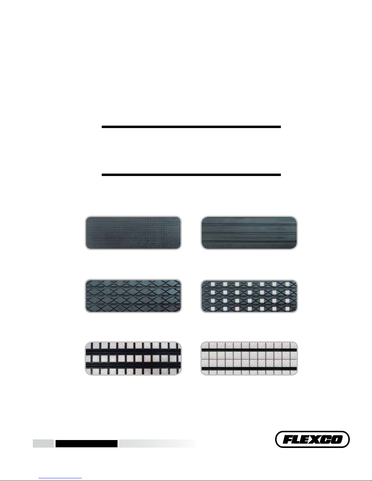
Light-Duty Plain-Pattern
Diamond-Pattern Rubber
Medium Ceramic (39%)
www.flexco.com
www.flexco.com
Diamond-Pattern Ceramic (13%)
Full Ceramic (80%)
Page 2

Flex-Lag® Cold Bond Pulley Lagging
Purchase Date: ______________________________________________________________
Purchased From: ____________________________________________________________
Installation Date: ____________________________________________________________
This information will be helpful for any future inquiries or questions
about replacement parts, specifications or troubleshooting.
2 Flex-Lag® Cold Bond Pulley Lagging
Page 3

Table of Contents
Section 1 – Important Information ....................................................................... 2
1.1 General Introduction .......................................................................................... 2
1.2 User Benets ........................................................................................................ 2
1.3 Service Option ..................................................................................................... 2
Section 2 – Safety Considerations and Precautions .............................................. 3
2.1 Stationary Conveyors .......................................................................................... 3
2.2 Operating Conveyors .......................................................................................... 3
Section 3 – Pre-Installation Checks and Options .................................................. 4
3.1 Checklist ............................................................................................................... 4
Section 4 – Installation Instructions...................................................................5-8
Section 5 – Pre-Operation Checklist and Testing.................................................. 9
5.1 Pre-Op Checklist ................................................................................................. 9
5.2 Test Run the Conveyor .......................................................................................9
Section 6 – Maintenance .................................................................................10-12
6.1 New Installation Inspection ............................................................................. 10
6.2 Routine Visual Inspection ................................................................................ 10
6.3 Routine Physical Inspection .............................................................................10
6.4 Maintenance Log ............................................................................................... 11
6.5 Lagging Maintenance Checklist ......................................................................12
Section 7 – Troubleshooting ................................................................................ 13
Section 8 – Specs and CAD Drawings............................................................. 13-21
8.1 Specications ......................................................................................................13
8.2 CAD drawing - Light Duty .............................................................................. 14
8.3 CAD drawing - Plain Rubber...........................................................................15
8.4 CAD drawing - Diamond-Pattern Rubber.....................................................16
8.5 CAD drawing - Diamond Ceramic .................................................................17
8.6 Medium Ceramic, Dimpled Tiles ....................................................................18
8.7 Medium Ceramic, Smooth Tiles ......................................................................19
8.8 Full Ceramic, Dimpled Tiles .......................................................................... 20
8.9 Full Ceramic, Smooth Tiles .............................................................................. 21
Section 9 – Lagging Adhesives/Toolbox .............................................................. 22
Section 10 – Other Flexco Conveyor Products .................................................... 25
1
Page 4

Section 1 – Important Information
1.1 General Introduction
We at Flexco are very pleased that you have selected Flex-Lag® Pulley Lagging for your conveyor system.
is manual will help you to understand the operation of this product and assist you in making it work up to
its maximum eciency over its lifetime of service.
It is essential for safe and ecient operation that the information and guidelines presented be properly
understood and implemented. is manual will provide safety precautions, installation instructions,
maintenance procedures and troubleshooting tips.
If, however, you have any questions or problems that are not covered, please contact your eld representative
or our Customer Service Department:
Customer Service: 1-800-541-8028
Visit www.exco.com for other Flexco locations and products.
Please read this manual thoroughly and pass it on to any others who will be directly responsible for
installation, operation and maintenance of this pulley lagging. While we have tried to make the installation
and service tasks as easy and simple as possible, it does however require correct installation and regular
inspections to maintain top working condition.
1.2 User Benets
Correct installation and regular maintenance will provide the following benets for your operation:
• Eliminate belt slippage
• Reduced conveyor downtime
• Reduced man-hour labor
• Lower maintenance budget costs
• Increased service life for the lagging and pulley
1.3 Service Option
Flex-Lag® Pulley Lagging is designed to be easily installed and serviced by your on-site personnel. However, if
you would prefer complete turn-key factory service, please contact your local Flexco Field Representative.
2 Flex-Lag® Cold Bond Pulley Lagging
Page 5
Section 2 – Safety Considerations and Precautions
Before installing and operating Flex-Lag® Pulley Lagging, it is important to review and understand the following safety
information.
There are set-up, maintenance and operational activities involving both stationary and operating conveyors. Each case
has a safety protocol.
2.1 Stationary Conveyors
The following activities are performed on stationary conveyors:
• Installation
• Cleaning
!
DANGER
It is imperative that OSHA/MSHA Lockout/Tagout
(LOTO) regulations, 29 CFR 1910.147, be followed before
undertaking the preceding activities. Failure to use LOTO
exposes workers to uncontrolled behavior of the products
caused by movement of the conveyor belt. Severe injury or
death can result.
Before working:
• Lockout/Tagout the conveyor power source
• Disengage any takeups
• Clear the conveyor belt or clamp securely in place
!
WARNING
Use Personal Protective Equipment (PPE):
• Safety eyewear (splash goggles optional)
• NIOSH-approved air respirator with organic
vapor cartridge (if ventilation is not available as
recommended in enclosed Safety Data Sheets)
• Hardhat • Long-sleeve shirt
• Safety footwear • Apron (optional)
• Nitrile gloves
Close quarters and heavy components create a worksite
that compromises a worker’s eyes, feet and skull.
PPE must be worn to control the foreseeable hazards
associated with conveyor lagging. Serious injuries can
be avoided.
2.2 Operating Conveyors
There are two routine tasks that must be performed while the conveyor is running:
• Inspection of performance
• Dynamic troubleshooting
!
DANGER
Every belt pulley is an in-running nip hazard. Never
touch or prod an operating pulley. Pulley hazards cause
instantaneous amputation and entrapment.
!
WARNING
Pulleys can become projectile hazards. Stay as far from the
pulley as practical and use safety eyewear and headgear.
Missiles can inflict serious injury.
!
WARNING
Never adjust anything on an operating pulley.
Unforseeable belt projections and tears can cause
violent movements. Flailing hardware can cause
serious injury or death.
3
Page 6

Section 3 – Pre-installation Checks and Options
3.1 Checklist
• Check that the lagging size is correct for the pulley width
• Check that the correct amount of lagging strips are available to lag the
pulley (see Page 6).
• Check that the correct amount of primer, adhesive and activator are
available to lag the pulley (see Page 6).
• Check the carton and make sure all the parts are included
• Review the “Tools Needed” list on the top of the installation instructions
• Check the conveyor site:
· Will the lagging be installed in a chute
· Is the install on an open head pulley
Flex-Lag Primer, Adhesive and Activator ONLY for use with
cold-bond rubber-to-rubber or rubber-to-metal adhesion.
4 Flex-Lag® Cold Bond Pulley Lagging
Page 7
Section 4 – Installation Instructions
If using non-Flexco adhesives, please follow that company’s instructions for usage, mixing, application and safety
procedures.
Flex-Lag® Pulley Lagging can be used with Flex-Lag Adhesives. Flex-Lag Adhesives consist of a Primer, Adhesive
and Activator. Before using, the Primer should be thoroughly mixed. Before using, one Adhesive and one Activator
should be thoroughly mixed and used within three hours. Reference the Adhesive Usage Charts on Page 6 for
quantity of each material required based on Pulley Diameter and Face Width.
ese materials are meant for use at room temperature. e ambient temperature and temperature of the lagging
and pulley must be between 41˚F113˚F (5˚C 45˚C), and the relative humidity should not exceed 80% during the
lagging procedure. ese should be checked prior to starting and occasionally during the lagging process to ensure
proper bonding.
Proper protective equipment should be used during the lagging process. Wear safety glasses with side shields.
Wear chemical splash goggles if the possibility exists for eye contact with splashing liquid. Avoid skin contact by
wearing chemically-resistant gloves (nitrile) and long sleeved shirt. An apron may be appropriate if splashing can
occur. Respiratory protection may be required to avoid overexposure when handling this product. If general room
ventilation is not available or sucient use a NIOSH-approved air purifying respirator with organic vapor cartridge.
Please reference the Safety Data Sheets for Adhesive, Activator and Primer to see detailed requirements. Also, please
follow any local or state guidelines for use of this product.
Fig. 1
Fig. 2
Physically lock out and tag the conveyor at the power source
before you begin pulley lagging installation.
Tools Needed:
• Grinder (low RPM recommended)
• 24 Grit Flap Disc
• Bench Brush
• Coarse Dish Wheel
• Paint Brushes
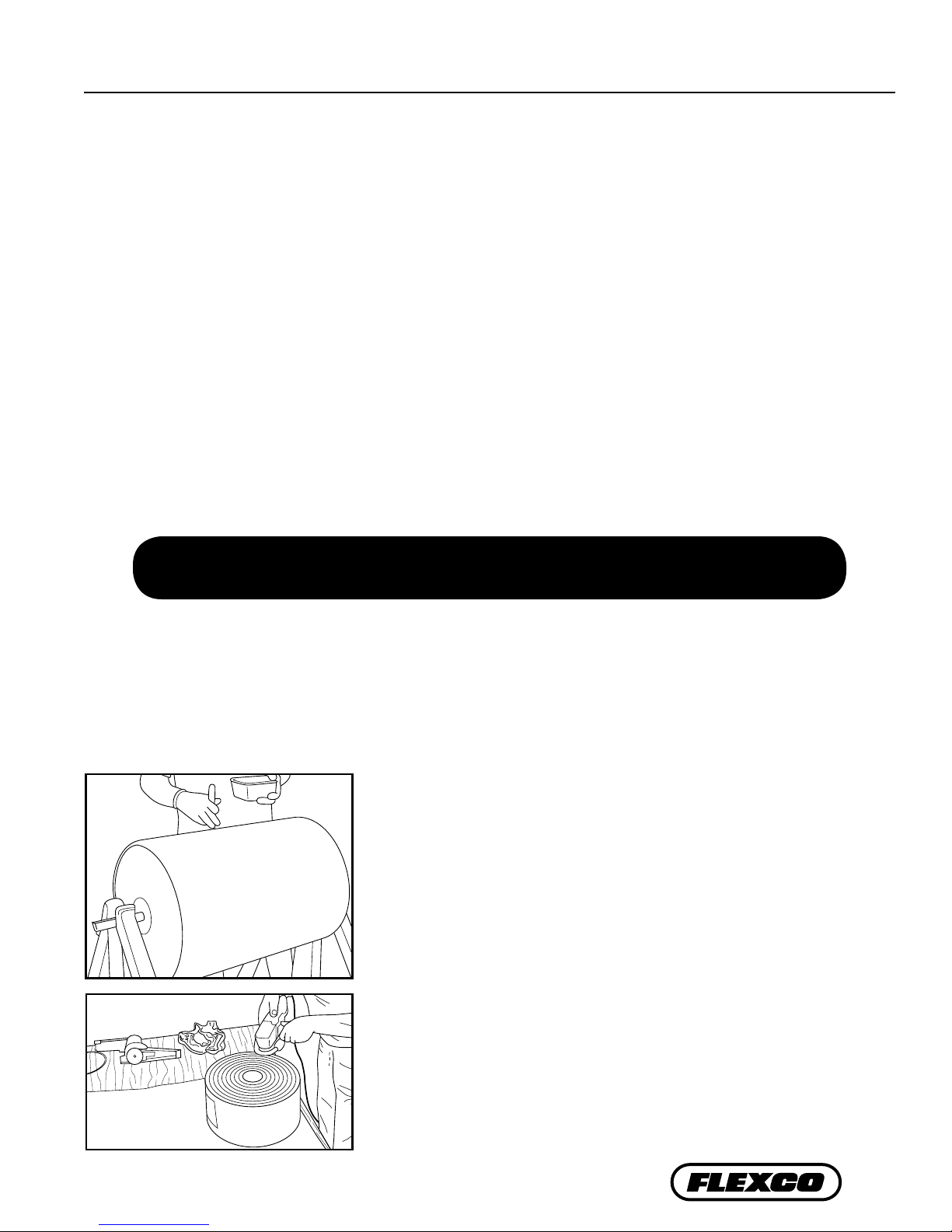
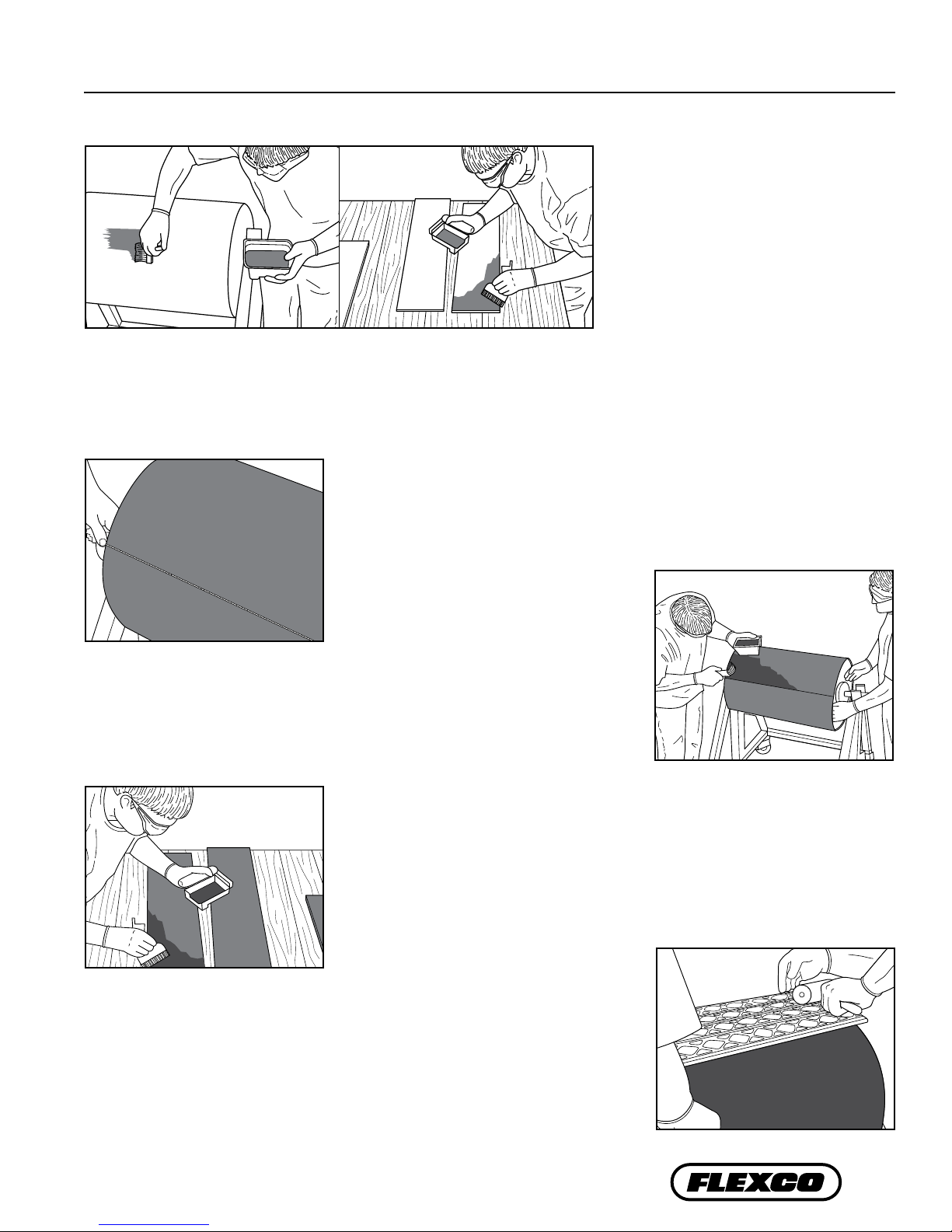
1. Prepare the pulley by removing the old lagging, paint and primer.
Sand blast the entire pulley or use a grinder with 24 grit flap disc or
paper disc. Use bench brush and non-oil-based metal solvent to clean
remaining particles from the pulley surface. Paint the pulley surface,
including the edges, with Flex-Lag Primer. Allow to dry completely –
a minimum of 30 minutes.
2. Use a grinder with coarse dish wheel to buff the edges and bottom
of the lagging. Be careful not to smoke the rubber. Wipe with non-
oil-based solvent to clean surface of any particles.
• Heavy Duty Knife
• Chalk Line
• Dead Blow Rubber Hammer
• Lagging Stitchers/Rollers
• Oscillating Tool (for cutting rubber)
5
Page 8
Section 4 – Installation Instructions (cont.)
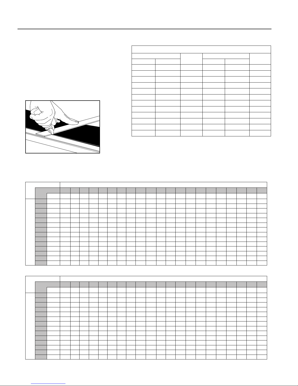
3. Use the Strip Selection Chart at right to
calculate the number of strips required for
your pulley diameter. Using a heavy duty
knife, cut lagging strips 4" (100mm) longer
than the pulley face width. Medium and Full
Ceramic lagging come in pre-specified strip
lengths. Note: Do not allow ceramic tiles to
sit at, or over, the edge of the pulley face.
PULLEY DIAMETER
in. mm in. mm
12.6-15.0 320-381 6 42.6-45.0 1083-1145 18
15.1-17.5 382-445 7 45.1-47.5 1146-1210 19
17.6-20.0 446-510 8 47.6-50.1 1211-1273 20
20.1-22.5 511-573 9 50.2-52.6 1274-1336 21
22.6-25.0 574-636 10 52.7-55.1 1337-1400 22
25.1-27.5 637-700 11 55.2-57.6 1403-1463 23
27.6-30.0 701-764 12 57.7-60.1 1466-1527 24
30.1-32.5 765-827 13 60.2-62.6 1529-1590 25
32.6-35.0 828-891 14 62.7-65.1 1593-1654 26
35.1-37.5 892-955 15 65.2-67.6 1656-1717 27
37.6-40.0 956-1018 16 67.7-70.1 1720-1781 28
40.1-42.5 1019-1082 17 70.2-72.6 1783-1844 29
Fig. 3
Adhesive, Activator and Primer Usage Charts
FLEX-LAG® ADHESIVE 0.8L / ACTIVATOR 40g (1:1 mix ratio)
Face Width
In. 10 14 18 22 26 30 34 38 42 46 50 54 58 62 66 70 74 78 82 86 90
Pulley Diameter
FLEX-LAG
Face Width
Pulley Diameter
mm 254 356 457 559 660 762 864 965 1067 1168 1270 1372 1473 1575 1676 1778 1880 1981 2083 2184 2286
8 203 1 1 1 1 1 1 1 1 2 2 2 2 2 2 2 2 2 2 3 3 3
12 305 1 1 1 1 1 2 2 2 2 2 2 3 3 3 3 3 3 3 4 4 4
16 406 1 1 1 2 2 2 2 2 3 3 3 3 3 4 4 4 4 4 5 5 5
20 508 1 1 2 2 2 2 3 3 3 3 4 4 4 4 5 5 5 5 6 6 6
24 610 1 2 2 2 2 3 3 3 4 4 4 5 5 5 5 6 6 6 7 7 7
28 711 1 2 2 2 3 3 3 4 4 5 5 5 6 6 6 7 7 7 8 8 8
32 813 2 2 2 3 3 4 4 4 5 5 6 6 6 7 7 8 8 8 9 9 10
36 914 2 2 3 3 3 4 4 5 5 6 6 7 7 8 8 8 9 9 10 10 11
40 1016 2 2 3 3 4 4 5 5 6 6 7 7 8 8 9 9 10 10 11 11 12
44 1118 2 2 3 4 4 5 5 6 6 7 7 8 9 9 10 10 11 11 12 12 13
48 1219 2 3 3 4 4 5 6 6 7 7 8 9 9 10 10 11 12 12 13 13 14
52 1321 2 3 3 4 5 5 6 7 7 8 9 9 10 11 11 12 13 13 14 15 15
56 1422 2 3 4 4 5 6 6 7 8 9 9 10 11 11 12 13 14 14 15 16 16
60 1524 2 3 4 5 5 6 7 8 8 9 10 11 11 12 13 14 14 15 16 17 17
®
PRIMER .75L
In. 10 14 18 22 26 30 34 38 42 46 50 54 58 62 66 70 74 78 82 86 90
mm 254 356 457 559 660 762 864 965 1067 1168 1270 1372 1473 1575 1676 1778 1880 1981 2083 2184 2286
8 203 1 1 1 1 1 1 1 1 1 1 1 1 1 1 1 1 1 1 1 1 1
12 305 1 1 1 1 1 1 1 1 1 1 1 1 1 1 1 1 1 1 1 1 1
16 406 1 1 1 1 1 1 1 1 1 1 1 1 1 1 1 1 1 1 1 1 1
20 508 1 1 1 1 1 1 1 1 1 1 1 1 1 1 1 1 1 1 1 1 1
24 610 1 1 1 1 1 1 1 1 1 1 1 1 1 1 1 1 1 1 1 1 1
28 711 1 1 1 1 1 1 1 1 1 1 1 1 1 1 1 1 1 1 1 1 1
32 813 1 1 1 1 1 1 1 1 1 1 1 1 1 1 1 1 1 1 1 1 1
36 914 1 1 1 1 1 1 1 1 1 1 1 1 1 1 1 1 1 1 1 1 2
40 1016 1 1 1 1 1 1 1 1 1 1 1 1 1 1 1 1 1 1 2 2 2
44 1118 1 1 1 1 1 1 1 1 1 1 1 1 1 1 1 1 2 2 2 2 2
48 1219 1 1 1 1 1 1 1 1 1 1 1 1 1 1 1 2 2 2 2 2 2
52 1321 1 1 1 1 1 1 1 1 1 1 1 1 1 2 2 2 2 2 2 2 2
56 1422 1 1 1 1 1 1 1 1 1 1 1 1 2 2 2 2 2 2 2 2 2
60 1524 1 1 1 1 1 1 1 1 1 1 1 2 2 2 2 2 2 2 2 2 2
Strip Selection
STRIPS
REQUIRED
PULLEY DIAMETER
STRIPS
REQUIRED
6 Flex-Lag® Cold Bond Pulley Lagging
Page 9
Section 4 – Installation Instructions (cont.)
Fig. 4a Fig. 4b
4. Apply first coat of adhesive. Thoroughly mix one can of adhesive and one activator at a time, immediately applying it
to the pulley and strips of lagging. Be sure to apply adhesive to the edges of the lagging as well. This process should use
half of the adhesive/activator required in the chart on Page 6. Note: Allow 4 hours for the first coat to properly cure.
Temperature and humidity will affect dry time.
Fig. 5
6. Apply second coat of adhesive to the pulley. Thoroughly mix one can of
adhesive and activator at a time. From the perpendicular line, apply the
second coat of adhesive to an area slightly greater than one strip of lagging.
Fig. 7
5. After the first coat of adhesive has dried completely, mark a line across the
pulley face using a chalk line or scriber, ensuring the line is parallel to the
shaft’s centerline and square to the edge of the pulley.
7. Apply a second coat of adhesive to one strip of lagging. Be sure to apply
adhesive to the edges of the lagging as well.
Fig. 6
8. After the second coat has reached the appropriate tackiness (approximately
2-5 minutes, touch with back of hand – feels tacky and leaves no adhesive on
hand) install one strip of lagging, using the perpendicular line to assure the
strip is square to the pulley. Working out from the center of the strip, use a
dead blow rubber hammer for tamping to remove the air gaps, ensuring all
surface area receives one hammer blow. Repeat this process with Lagging
Stitchers/Rollers to remove air gaps from drainage grooves. Be sure to check
edges to verify seal.
Fig. 8
7
Page 10
Section 4 – Installation Instructions (cont.)
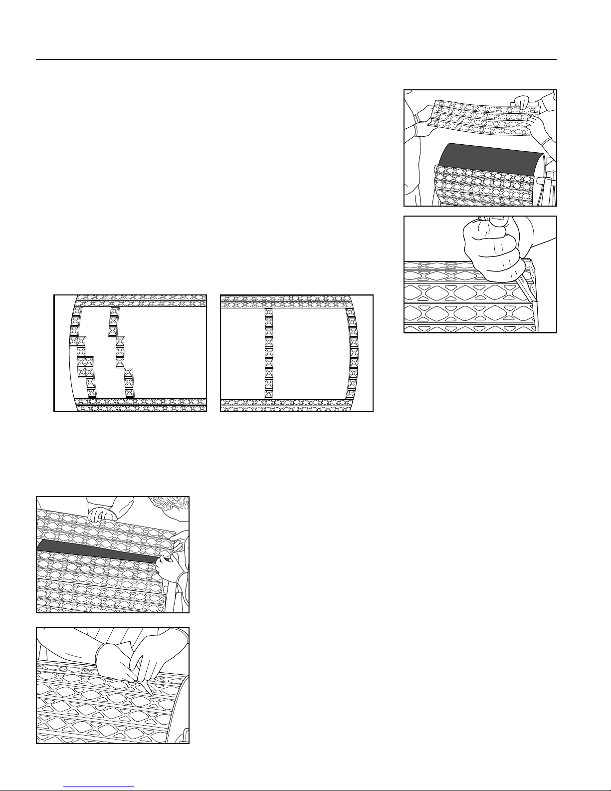
9. Repeat Steps 6 and 7, then place the second strip of lagging against the first,
taking care to ensure there are no gaps between the lagging. Shift lagging sideto-side to align diamond/ceramic patterns. Additional stitching between strips
may be required to remove any gaps. Repeat the tamping and stitching process
in Step 8 to remove air gaps from the applied strip.
10. Trim the excess lagging from applied strips at the edge of the pulley using a
heavy duty knife or oscillating tool. Trim lagging at an angle up and away from
the pulley edge. This can be done every one or two strips.
Fig. 11a
Fig. 11b
Fig. 9
Fig. 10
11. To apply the last 3-4 strips, position cut-off pieces of lagging from Step 10 in the unlagged portion of the pulley.
Manipulate the pieces to determine trim requirements for the last few strips. Trim the pieces in the gutters to find the
proper fit. Use the pieces as templates to trim the last few strips of lagging. Note: Final strips should not consist of
less than three rows.
Fig. 12
Fig. 13
12. Follow Steps 6 through 10 to install the last 3-4 strips. The final piece of
lagging (largest of final pieces) should drop into position. Check the fit of the
last piece prior to applying the second coat of adhesive.
13. Fill any gaps between the lagging strips with rubber sealer. Also use the
buffing wheel on trimmed edge of lagging and apply final coat of adhesive
to seal the edge and joint area between lagging strips.
Note: Allow minimum of 24 hours of curing time before putting newly
lagged pulley into use.
8 Flex-Lag® Cold Bond Pulley Lagging
Page 11

Section 5 – Pre-Operation Checklist and Testing
5.1 Pre-Op Checklist
• Be sure that all installation materials and tools have been removed from the belt and the conveyor area.
5.2 Test Run the Conveyor
• Run the conveyor for at least 15 minutes and inspect the lagging performance.
NOTE: Observing the pulley lagging when it is running and performing properly will help to detect problems.
9
Page 12

Section 6 – Maintenance
Flexco lagging is designed to operate with minimum maintenance. However, to maintain superior performance some
service is required. This service will ensure that the lagging operates at optimal efficiency and problems can be identified
and fixed before the lagging stops working.
All safety procedures for inspection of equipment (stationary or operating) must be observed. Flex-Lag® Pulley Lagging
operates on all pulleys in the conveyor and is in direct contact with the moving belt. Only visual observations can be made
while the belt is running. Service tasks can be done only with the conveyor stopped and by observing the correct lockout/
tagout procedures.
6.1 New Installation Inspection
After the new lagging has run for a few days a visual inspection should be made to ensure the lagging is performing
prop erly.
6.2 Routine Visual Inspection (every 6-8 weeks)
A visual inspection of the lagging and belt can determine:
• If there is damage to the lagging.
• If fugitive material is built up on the lagging.
• If there is damage to the belt.
If any of the above conditions exist, a determination should be made on when the conveyor can be stopped for additional
maintenance.
6.3 Routine Physical Inspection (every 3-4 months)
When the conveyor is not in operation and properly locked and tagged out, conduct a physical inspection of the lagging
to perform the following tasks:
• Clean material buildup off of the lagging.
• Closely inspect the lagging for wear and any damage.
• Ensure full lagging to belt contact.
• Inspect the belt for damage.
• Replace any worn or damaged components.
• When maintenance tasks are completed, test run the conveyor to ensure the lagging is performing properly.
10 Flex-Lag® Cold Bond Pulley Lagging
Page 13

Section 6 – Maintenance (cont.)
6.4 Maintenance Log
Conveyor Name/No.
Date: Work done by: Service Quote #
Activity:
Date: Work done by: Service Quote #
Activity:
Date: Work done by: Service Quote #
Activity:
Date: Work done by: Service Quote #
Activity:
Date: Work done by: Service Quote #
Activity:
Date: Work done by: Service Quote #
Activity:
Date: Work done by: Service Quote #
Activity:
11
Page 14

Section 6 – Maintenance (cont.)
6.6 Lagging Maintenance Checklist
Site: ______________________________ Inspected by: ________________________________ Date: ______________________________
Lagging: _________________________________________________
Beltline Information:
Beltline Number: ____________________ Belt Condition: ___________________________________________________________________
Belt (18") (24") (30") (36") (42") (48") (54") (60") (72")
Width: ¨ 450mm ¨ 600mm ¨ 750mm ¨ 900mm ¨ 1050mm ¨ 1200mm ¨ 1350mm ¨ 1500mm ¨ 1800mm
Head Pulley Diameter (Belt & Lagging):__________ Belt Speed:________ fpm or m/s Belt Thickness: __________
Belt Splice:__________ Condition of Splice:_________ Number of Splices:________ ¨ Skived ¨ Unskived
Material conveyed: ____________________________________________________________________________________________________
Days per week run:_______________ Hours per day run:_______________
Lagging Life:
Date installed:___________ Date inspected:___________ Estimated life:____________
Lagging Thickness:___________
Lagging: ¨ Side Lag ¨ Ceramic ¨ Rubber ¨ Other ¨ None
Condition of lagging: ¨ Good ¨ Bad ¨ Other
Cleaner's Overall Performance: (Rate the following 1 - 5, 1= very poor - 5 = very good)
Appearance: ¨ Comments: ________________________________________________________________________________________
Location: ¨ Comments: ________________________________________________________________________________________
Maintenance: ¨ Comments: ________________________________________________________________________________________
Performance: ¨ Comments: ________________________________________________________________________________________
Other comments: ______________________________________________________________________________________________________
____________________________________________________________________________________________________________________
____________________________________________________________________________________________________________________
____________________________________________________________________________________________________________________
____________________________________________________________________________________________________________________
____________________________________________________________________________________________________________________
____________________________________________________________________________________________________________________
____________________________________________________________________________________________________________________
____________________________________________________________________________________________________________________
12 Flex-Lag® Cold Bond Pulley Lagging
Page 15

Section 7 – Troubleshooting
Problem Possible Cause Possible Solutions
Uneven wear in rubber
lagging
Belt Tension
Short Transition Increase distance to full trough idler
Change to ceramic lagging
Wrong Lagging for Application Increase thickness or change to ceramic lagging
Glue too wet or dry when applied
Refer to instructions on p. 5-8 for proper installation instructions
Delaminating
Pulley surface not prepped correctly Refer to instructions on p. 5-8 for proper installation instructions
For additional troubleshooting questions, please contact Customer Service or your territory manager.
Section 8 – Specifications and CAD Drawings
8.1 Specications
®
Rubber
Plain
3/8" – 1"
(10 – 25 mm)
Any Width
12" (300mm)
Excellent
Average
Very Good
Good
Yes
Yes
Flex-Lag
Diamond
3/8" – 1"
(10 – 25 mm)
Any Width Any Width
12" (300mm) 12" (300mm) 12" (300mm) 12" (300mm) 16" (400mm) 16" (400mm)
Excellent Excellent Excellent Excellent Excellent Excellent
Good Very Good Excellent Excellent Good Excellent
Very Good Excellent Excellent Excellent Very Good Excellent
Good Good Good Good Excellent Excellent
Yes Yes Yes Ye s Ye s Yes
Yes Yes Yes Ye s Ye s Yes
Diamond
Ceramic
1/2"
(12.7 mm)
Criteria
Total Thickness*
Belt Width*
Minimum Pulley Diameter
Dry Performance
Wet Performance
Wear Life
Ease of Installation
Drainage Grooves
FRAS (Fire Resistant Anti Static)
Light Duty
19/64"
(7.5 mm)
Any Width
12" (300mm)
Very Good
Average
Good
Good
No
No
Flex-Lag
Rubber Compound
Hardness (Shore A)
Ceramic Compound
Hardness (HRA Rockwell Scale A)
Ceramic Coverage
Operating Temperature
A1
2O3
83 83 83
13% 39% 80%
(-15° – 85° C)
*Additional thicknesses and widths available as special orders. For weld-on lagging, this includes the steel backing plate.
Medium
Ceramic
(450 – 2100 mm)
SBR
68 +/-3
5° – 185° F
®
Ceramic Flex-Lag® Weld-On
Full Ceramic
5/8"
(15 mm)
18" – 84"
A12O
3
1/2"
(12.7 mm)
18" – 84"
(450 – 2100 mm)
A12O
3
Rubber
Diamond
9/16"
(14 mm)
18" – 72"
(450 – 1800 mm)
Full Ceramic
5/8"
(15 mm)
18" – 72"
(450 – 1800 mm)
A1
2O3
83
74%
™
13
Page 16

Section 8 – Specifications and CAD Drawings (cont.)
DESCRIPTION
WHITE NITRILE
BLACK NATURAL
RUBBER
8.2 Lagging - Light Duty Rubber
0.75
0.25
+0.25
+
6 -
7.5 -0.75
200 - 0.5
+0.5
3300
71076
ITEM CODE
NUMBER
ORDERING
7.5WLD3.3/11
RUBBER
71077
7.5NLD3.3/11
14 Flex-Lag® Cold Bond Pulley Lagging
Page 17

6500
Section 8 – Specifications and CAD Drawings (cont.)
SECTION
A-A
SCALE
1 : 4
45°
11.0
7.0
DETAIL B
NATURAL RUBBER
THICKNESS
THICKNESS
32
ALL MACHINED SURFACES
9/19/2013
REMOVE BURRS & BREAK SHARP EDGES
UNSPECIFIED SHARP EDGES & FILLETS
WITHIN 1 mm (.04 in)
SURFACE ROUGHNESS
102
REV.
DRAWN BY: TLC
GR-25780
DOC. ID
LAGGING
1
of
1
SCALE: 1:1
DATE:09/26/2013
PLAIN LAGGIN
THIRD ANGLE PROJECTION
TOLERANCES - mm (INCH)
(UNLESS OTHERWISE SPECIFIED)
X.XX
.1 (0.004 in)
X.X
.5 (0.020 in)
X
1 (0.04 in)
Ang.
1
THIS DRAWING IN DESIGN AND DETAIL IS
THE PROPERTY OF FLEXIBLE STEEL LACING CO.
AND MAY NOT BE USED EXCEPT IN CONNECTION
WITH OUR WORK. ALL RIGHTS OF INVENTION OR
DESIGN ARE RESERVED. RETURN UPON REQUEST.
CONFIDENTIAL! NO COPYING OR REPRODUCING!
DRAWING NO.
SIZE: A
SHEET
TITLE:
1995 OAK INDUSTRIAL DRIVE, N.E.
GRAND RAPIDS, MI. 49505
PHONE: (616) 459-3196
FAX: (616) 459-4976
71010T
8.3 Lagging - Plain Rubber
16
18
23
WEIGHT
NUMBER
ORDERING
10NP6.5/21
12NP6.5/21
ITEM
CODE
71012
12
10 71010
15NP6.5/21
71017
15
THICKNESS -0.75
+0.25
200 - 0.5
+ 0.5
29
26
20NP6.5/21
25NP6.5/21
FRAS RUBBER
71021
71163
20
25
17
20
WEIGHT
NUMBER
ORDERING
10FRP6.5/21
12FRP6.5/21
ITEM
CODE
10 71020
12 71022
24
27
15FRP6.5/21
20FRP6.5/21
15 71015
20 72129
A
DETAIL A
SCALE 1 : 2
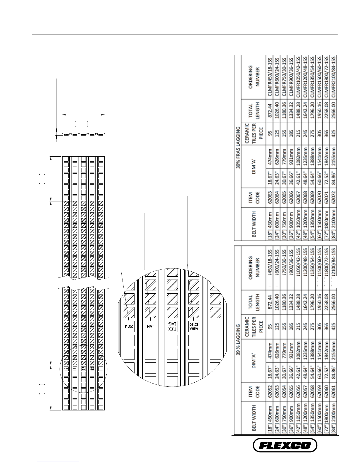
MANUFACTURE DATE
(MONTH YEAR)
MATERIAL
"NAT" - NATURAL RUBBER
"MSHA IC190" - FRAS
15
Page 18

Section 8 – Specifications and CAD Drawings (cont.)
THICKNESS
8.4 Lagging - Diamond-Pattern Rubber
THICKNESS -0.75
+0.25
200 - 0.5
+0.5
24
18
14.5
WEIGHT
NUMBER
ORDERING
15FRD6.5/21
10FRD6.5/21
12FRD6.5/21
FRAS RUBBER
ITEM CODE
27
20FRD6.5/21
6500
DETAIL A
A
MANUFACTURE DATE (MONTH/YEAR)
SCALE 1 : 2
MATERIAL -
"NAT" - NATURAL RUBBER
"MSHA IC 190" - FRAS
15 71018
12 71016
10 71014
THICKNESS
13
17
22
24
WEIGHT
NUMBER
ORDERING
10ND6.5/21
12ND6.5/21
15ND6.5/21
20ND6.5/21
NATURAL RUBBER
ITEM CODE
12 71004
15 71006
10 71002
20 71008
20 71019
2725 71152
25ND6.5/21
16 Flex-Lag® Cold Bond Pulley Lagging
Page 19

Section 8 – Specifications and CAD Drawings (cont.)
THICKNESS
MATERIAL
ITEM CODE
ORDERING
NUMBER
WEIGHT
QTY. TILES
12
NATURAL RUBBER
71155
12NDC6.5/21
25 328
12
FRAS
71159
12FRDC6.5/21
27 328
71155T
1995 OAK INDUSTRIAL DRIVE, N.E.
GRAND RAPIDS, MI. 49505
PHONE: (616) 459-3196
FAX: (616) 459-4976
TITLE:
DRAWN BY: KAC
SHEET
SCALE:
SIZE: B
DRAWING NO.
THIS DRAWING IN DESIGN AND DETAIL IS
THE PROPERTY OF FLEXIBLE STEEL LACING CO.
AND MAY NOT BE USED EXCEPT IN CONNECTION
WITH OUR WORK. ALL RIGHTS OF INVENTION OR
DESIGN ARE RESERVED. RETURN UPON REQUEST.
CONFIDENTIAL! NO COPYING OR REPRODUCING!
THIRD ANGLE PROJECTION
DIAMOND LAGGING NAT/FRAS
DATE:01/16/2014
1:5
1
of
1
X
XX-XXXXX
DOC. ID
TOLERANCES - INCH (mm)
(UNLESS OTHERWISE SPECIFIED)
.XXX
.005 (0.13mm)
.XX
.015 (0.38mm)
FRACT.
1/16 (1.59mm)
Ang.
1
REMOVE BURRS & BREAK SHARP EDGES
UNSPECIFIED SHARP EDGES & FILLETS
WITHIN 1/32 (.79mm)
REV.
100
6500
8.5 Lagging - Diamond Ceramic
+0.25
12 -0.75
200 - 0.5
+0.5
TILE ITEM CODE P3673
77 TYP.
17
Page 20

Section 8 – Specifications and CAD Drawings (cont.)
REMOVE BURRS & BREAK SHARP EDGES
UNSPECIFIED SHARP EDGES & FILLETS
WITHIN 1/32 (.79mm)
SURFACE ROUGHNESS
125
ALL MACHINED SURFACES
203
8.0
203
8.0
CERAMIC TILE LENGTH - DIM 'A'
196
7.72
15
0.59
NOTE: SAMPLE PART NUMBER L0493
THIS DRAWING IN DESIGN AND DETAIL IS
THE PROPERTY OF FLEXIBLE STEEL LACING CO.
AND MAY NOT BE USED EXCEPT IN CONNECTION
WITH OUR WORK. ALL RIGHTS OF INVENTION OR
DESIGN ARE RESERVED. RETURN UPON REQUEST.
CONFIDENTIAL! NO COPYING OR REPRODUCING!
61294T
1995 OAK INDUSTRIAL DRIVE, N.E.
GRAND RAPIDS, MI. 49505
PHONE: (616) 459-3196
FAX: (616) 459-4976
TITLE:
SHEET
SIZE: A
DRAWING NO.
TOLERANCES - INCH (mm)
(UNLESS OTHERWISE SPECIFIED)
.XXX
.005 (0.13mm)
.XX
.015 (0.38mm)
FRACT.
1/16 (1.59mm)
Ang.
1
THIRD ANGLE PROJECTION
39% STRIP LAGGING
DATE:11/9/2010
SCALE: 1:5
1
of
2
DOC. ID
GR-24308
DRAWN BY: TLC
REV.
103
10/11/2013
SCALE 1 : 2
8.6 Lagging - Medium Ceramic, Dimpled Tiles, Natural and FRAS
0.01
+
0.03
-
0.59
0.25
+
0.75
-
15
203.5
8.01
8.0
YEAR MANUFACTURED
MONTH MANUFACTURED
DIMENSIONS IN BRACKETS INCHES
NOTES:
MATERIAL
"NAT" - NATURAL RUBBER
"MSHA IC190" - FRAS RUBBER
CLMN
CLMN
CLMN
CLMN
CLMN
CLMN
CLMN
CLMN
CLMN
CLMN
CLMN
CERAMIC LENGTH - DIM 'A' 203
A
8.0
203
DETAIL A
18 Flex-Lag® Cold Bond Pulley Lagging
62216
Page 21
Section 8 – Specifications and CAD Drawings (cont.)
REMOVE BURRS & BREAK SHARP EDGES
UNSPECIFIED SHARP EDGES & FILLETS
WITHIN 1/32 (.79mm)
SURFACE ROUGHNESS
125
ALL MACHINED SURFACES
203
8.0
203
8.0
CERAMIC LENGTH - DIM 'A'
13
0.51
196
7.72
THIS DRAWING IN DESIGN AND DETAIL IS
THE PROPERTY OF FLEXIBLE STEEL LACING CO.
AND MAY NOT BE USED EXCEPT IN CONNECTION
WITH OUR WORK. ALL RIGHTS OF INVENTION OR
DESIGN ARE RESERVED. RETURN UPON REQUEST.
CONFIDENTIAL! NO COPYING OR REPRODUCING!
61294T
1995 OAK INDUSTRIAL DRIVE, N.E.
GRAND RAPIDS, MI. 49505
PHONE: (616) 459-3196
FAX: (616) 459-4976
TITLE:
SHEET
SIZE: A
DRAWING NO.
TOLERANCES - INCH (mm)
(UNLESS OTHERWISE SPECIFIED)
.XXX
.005 (0.13mm)
.XX
.015 (0.38mm)
FRACT.
1/16 (1.59mm)
Ang.
1
THIRD ANGLE PROJECTION
39% STRIP LAGGING
DATE:11/9/2010
SCALE: 1:5
2
of
2
DOC. ID
GR-24308
DRAWN BY: TLC
REV.
103
10/11/2013
SCALE 1 : 2
8.7 Lagging - Medium Ceramic, Smooth Tiles, Natural and FRAS
+0.01
0.59 - 0.03
+0.25
15 - 0.75
203.5
8.01
8.0
203
CERAMIC LENGTH - DIM 'A'
NOTES:
DIMENSIONS IN BRACKETS INCHES
MATERIAL
"NAT" - NATURAL RUBBER
YEAR MANUFACTURE
MONTH MANUFACTURE
"MSHA IC190" - FRAS RUBBER
CLMN
CLMN
CLMN
CLMN
CLMN
CLMN
CLMN
CLMN
CLMN
CLMN
A
8.0
203
DETAIL A
19
Page 22

Section 8 – Specifications and CAD Drawings (cont.)
B
SECTION
A-A
SCALE 1 : 2
45°
11 7
DETAIL B
SCALE 1 : 1
REFERENCE TABLE FOR FULL CERAMIC NATURAL RUBBER
ITEM CODE
71111
1995 OAK INDUSTRIAL DRIVE, N.E.
GRAND RAPIDS, MI. 49505
PHONE: (616) 459-3196
FAX: (616) 459-4976
TITLE:
SHEET
SIZE: B
DRAWING NO.
THIS DRAWING IN DESIGN AND DETAIL IS
THE PROPERTY OF FLEXIBLE STEEL LACING CO.
AND MAY NOT BE USED EXCEPT IN CONNECTION
WITH OUR WORK. ALL RIGHTS OF INVENTION OR
DESIGN ARE RESERVED. RETURN UPON REQUEST.
CONFIDENTIAL! NO COPYING OR REPRODUCING!
TOLERANCES - mm (INCH)
(UNLESS OTHERWISE SPECIFIED)
X.XX
.1 (0.004 in)
X.X
.5 (0.020 in)
X
1 (0.04 in)
Ang.
1
THIRD ANGLE PROJECTION
FULL CERAMIC DIMPLE LAGGING
DATE:10/11/2008
SCALE: 1:33.3
1
of
2
LAGGING
DOC. ID
GR-22262
DRAWN BY: MJC
REV.
103
REMOVE BURRS & BREAK SHARP EDGES
UNSPECIFIED SHARP EDGES & FILLETS
WITHIN 1 mm (.04 in)
SURFACE ROUGHNESS
8/13/2013
125
ALL OVER
+0.25
MATERIAL
MANUFACTUR
(MONTH
8.8 Lagging - Full Ceramic, Dimpled Tiles, Natural and FRAS
OVERALL
LENGTH DIM 'B'
460 860
DIM 'A'
CERAMIC SPAN
NUMBER
ORDERING
CLFR460/18.4-12
71118
ITEM CODE
REFERENCE TABLE FOR FULL CERAMIC FRAS COMPOUND LAGGING
OVERALL
LENGTH DIM 'B'
12 -0.75
7.5
515151
±0.5203
B
SCALE 1 : 2
SECTION A-A
600 1000
760 1160
800 1200
900 1300
1060 1500
CLFR600/24-12
CLFR800/32-12
CLFR900/36-12
CLFR760/30.4-12
CLFR1060/42.4-12
71120
71121
71122
71123
71119
1200 1600
1360 1800
1400 1900
1520 2000
1600 2100
1700 2200
CLFR1200/48-12
CLFR1400/56-12
CLFR1600/64-12
CLFR1700/68-12
CLFR1360/54.4-12
CLFR1520/60.8-12
71005
71007
71009
71124
71078
A1636
1800 2300
1900 2400
2000 2500
2100 2600
2200 2700
2300 2800
CLFR1800/72-12
CLFR1900/76-12
CLFR2000/80-12
CLFR2100/84-12
CLFR2200/88-12
CLFR2300/92-12
71079
71080
71081
71082
71083
71084
2400 2900
2500 3000
2600 3000
2800 3300
3000 3300
CLFR2400/96-12
CLFR2500/100-12
CLFR2600/104-12
CLFR2800/112-12
CLFR3000/120-12
71085
71086
71087
71088
71089
10
DIM 'B'
600 1000
460 860
760 1160
800 1200
900 1300
1060 1500
1200 1600
1360 1800
1400 1900
1520 2000
1600 2100
1700 2200
1800 2300
1900 2400
2000 2500
2100 2600
2200 2700
2300 2800
2400 2900
2500 3000
2600 3000
2800 3300
+0.25
=
12 - 0.75
7.5
CERAMIC
SPAN DIM 'A'
3000 3300
LAGGING
A
A
11
SCALE 1 : 1
DETAIL B TYP.
NUMBER
ORDERING
CLN600/24-12
CLN460/18.4-12
71111
71112
CLN800/32-12
CLN900/36-12
CLN1200/48-12
CLN760/30.4-12
CLN1060/42.4-12
CLN1360/54.4-12
71113
71114
71115
71116
71039
71126
CLN1400/56-12
CLN1600/64-12
CLN1700/68-12
CLN1800/72-12
CLN1520/60.8-12
71040
71127
71117
71041
71042
CLN1900/76-12
CLN2000/80-12
CLN2100/84-12
CLN2200/88-12
CLN2300/92-12
71043
71037
71044
71045
71046
CLN2400/96-12
CLN2500/100-12
CLN2600/104-12
CLN2800/112-12
CLN3000/120-12
71047
71048
71049
71050
71000
+20
DIM 'A' 0
CERAMIC TILE
DETAIL C
SCALE 1 : 2
P2924
C
=
E DATE
-
YEAR)
20 Flex-Lag® Cold Bond Pulley Lagging
"NAT" - NATURAL RUBBER
"MSHA IC190" - FRAS
Page 23

REFERENCE TABLE FOR FULL CERAMIC NATURAL RUBBER
ITEM CODE
Section 8 – Specifications and CAD Drawings (cont.)
+0.25
MATERIAL
MANUFACTUR
(MONTH
8.9 Lagging - Full Ceramic, Smooth Tiles, Natural and FRAS
OVERALL
LENGTH DIM 'B'
460 860
600 1000
760 1160
800 1200
900 1300
1060 1500
1200 1600
1360 1800
CERAMIC
SPAN DIM 'A'
1400 1900
1520 2000
1600 2100
1700 2200
1800 2300
1900 2400
2000 2500
2100 2600
2200 2700
2300 2800
2400 2900
2500 3000
2600 3000
2800 3300
3000 3300
12 - 0.75
7.5
+0.25
12 -0.75
7.5
11
±0.5203
51 5151
SCALE 1 : 1
DETAIL B TYP.
LAGGING
NUMBER
ORDERING
CLFR600/24-12S
CLFR800/32-12S
CLFR900/36-12S
CLFR1200/48-12S
CLFR1400/56-12S
CLFR1600/64-12S
CLFR1700/68-12S
CLFR1800/72-12S
CLFR1900/76-12S
CLFR2000/80-12S
79418
79419
79420
CLFR2100/84-12S
79421
CLFR460/18.4-12S
CLFR760/30.4-12S
CLFR1060/42.4-12S
CLFR1360/54.4-12S
CLFR1520/60.8-12S
79407
79406
79408
79409
79410
79411
79412
79413
79414
79415
79416
REFERENCE TABLE FOR FULL CERAMIC FRAS COMPOUND
ITEM CODE
79417
CLFR2200/88-12S
CLFR2300/92-12S
CLFR2400/96-12S
CLFR2500/100-12S
CLFR2600/104-12S
CLFR2800/112-12S
79422
79423
79424
79425
79426
79427
CLFR3000/120-12S
79428
B
SCALE 1 : 2
SECTION A-A
OVERALL
LENGTH DIM 'B'
460 860
600 1000
760 1160
800 1200
900 1300
1060 1500
1200 1600
1360 1800
1400 1900
1520 2000
1600 2100
1700 2200
1800 2300
1900 2400
=
A
A
CERAMIC
SPAN DIM 'A'
LAGGING
NUMBER
ORDERING
CLN600/24-12S
CLN800/32-12S
CLN460/18.4-12S
CLN900/36-12S
CLN760/30.4-12S
CLN1060/42.4-12S
CLN1400/56-12S
CLN1200/48-12S
CLN1600/64-12S
CLN1360/54.4-12S
CLN1520/60.8-12S
2000 2500
CLN1700/68-12S
CLN1800/72-12S
CLN1900/76-12S
CLN2000/80-12S
2400 2900
2100 2600
CLN2100/84-12S
2500 3000
2200 2700
2300 2800
CLN2200/88-12S
CLN2300/92-12S
CLN2400/96-12S
CLN2500/100-12S
2600 3000
2800 3300
3000 3300
CLN2600/104-12S
CLN2800/112-12S
CLN3000/120-12S
10
+20
DIM 'B'
DIM 'A' 0
=
P2924
CERAMIC TILE
79384
79385
79383
DETAIL C
SCALE 1 : 2
79386
79387
79388
79389
79390
79391
79392
79393
79394
79395
79396
79397
79398
79399
79400
79401
79402
79403
79404
79405
C
E DATE
-
YEAR)
"MSHA IC190" - FRAS
"NAT" - NATURAL RUBBER
21
Page 24

Section 9 – Lagging Adhesives and Toolbox
Flex-Lag® Adhesive/Activator/Primer
ORDERING NUMBER DESCRIPTION ITEM CODE WEIGHT VOLUME
FL-ADH-0.8 Adhesive 75017
FL-ACT Activator 70186
FL-PR-0.75 Primer 70189
Each Flex-Lag® Adhesive is mixed with one Flex-Lag Activator.
Refer to the usage chart below to calculate the number of cans
required for your pulley. For sizes not included in the chart
please contact Flexco Customer Service for assistance.
FLEX-LAG® ADHESIVE 0.8L / ACTIVATOR 40g (1:1 mix ratio)
Face Width
In. 10 14 18 22 26 30 34 38 42 46 50 54 58 62 66 70 74 78 82 86 90
Pulley Diameter
FLEX-LAG
Face Width
Pulley Diameter
mm 254 356 457 559 660 762 864 965 1067 1168 1270 1372 1473 1575 1676 1778 1880 1981 2083 2184 2286
8 203 1 1 1 1 1 1 1 1 2 2 2 2 2 2 2 2 2 2 3 3 3
12 305 1 1 1 1 1 2 2 2 2 2 2 3 3 3 3 3 3 3 4 4 4
16 406 1 1 1 2 2 2 2 2 3 3 3 3 3 4 4 4 4 4 5 5 5
20 508 1 1 2 2 2 2 3 3 3 3 4 4 4 4 5 5 5 5 6 6 6
24 610 1 2 2 2 2 3 3 3 4 4 4 5 5 5 5 6 6 6 7 7 7
28 711 1 2 2 2 3 3 3 4 4 5 5 5 6 6 6 7 7 7 8 8 8
32 813 2 2 2 3 3 4 4 4 5 5 6 6 6 7 7 8 8 8 9 9 10
36 914 2 2 3 3 3 4 4 5 5 6 6 7 7 8 8 8 9 9 10 10 11
40 1016 2 2 3 3 4 4 5 5 6 6 7 7 8 8 9 9 10 10 11 11 12
44 1118 2 2 3 4 4 5 5 6 6 7 7 8 9 9 10 10 11 11 12 12 13
48 1219 2 3 3 4 4 5 6 6 7 7 8 9 9 10 10 11 12 12 13 13 14
52 1321 2 3 3 4 5 5 6 7 7 8 9 9 10 11 11 12 13 13 14 15 15
56 1422 2 3 4 4 5 6 6 7 8 9 9 10 11 11 12 13 14 14 15 16 16
60 1524 2 3 4 5 5 6 7 8 8 9 10 11 11 12 13 14 14 15 16 17 17
®
PRIMER .75L
In. 10 14 18 22 26 30 34 38 42 46 50 54 58 62 66 70 74 78 82 86 90
mm 254 356 457 559 660 762 864 965 1067 1168 1270 1372 1473 1575 1676 1778 1880 1981 2083 2184 2286
8 203 1 1 1 1 1 1 1 1 1 1 1 1 1 1 1 1 1 1 1 1 1
12 305 1 1 1 1 1 1 1 1 1 1 1 1 1 1 1 1 1 1 1 1 1
16 406 1 1 1 1 1 1 1 1 1 1 1 1 1 1 1 1 1 1 1 1 1
20 508 1 1 1 1 1 1 1 1 1 1 1 1 1 1 1 1 1 1 1 1 1
24 610 1 1 1 1 1 1 1 1 1 1 1 1 1 1 1 1 1 1 1 1 1
28 711 1 1 1 1 1 1 1 1 1 1 1 1 1 1 1 1 1 1 1 1 1
32 813 1 1 1 1 1 1 1 1 1 1 1 1 1 1 1 1 1 1 1 1 1
36 914 1 1 1 1 1 1 1 1 1 1 1 1 1 1 1 1 1 1 1 1 2
40 1016 1 1 1 1 1 1 1 1 1 1 1 1 1 1 1 1 1 1 2 2 2
44 1118 1 1 1 1 1 1 1 1 1 1 1 1 1 1 1 1 2 2 2 2 2
48 1219 1 1 1 1 1 1 1 1 1 1 1 1 1 1 1 2 2 2 2 2 2
52 1321 1 1 1 1 1 1 1 1 1 1 1 1 1 2 2 2 2 2 2 2 2
56 1422 1 1 1 1 1 1 1 1 1 1 1 1 2 2 2 2 2 2 2 2 2
60 1524 1 1 1 1 1 1 1 1 1 1 1 2 2 2 2 2 2 2 2 2 2
1.6 lb. 0.7 Kg 27.1 oz 0.8L
0.1 lb. 40 g - -
1.6 lb. 0.7 Kg 25.4 oz 0.75L
Flex-Lag® Toolbox
ORDERING NUMBER DESCRIPTION ITEM CODE WT. (LBS)
LAGGING-TB with Power Tools 79080
LAGGING-TB2 without Power Tools 79099
Both Include:
• 25-ft measuring tape • Paint brushes (3) • HD knife and replacement blades
• BCP location tool • Lagging stitchers (3) • Bench brush
• Chalk line • White paint marker • Deadblow hammer
LAGGING-TB Also Includes:
• Air hammer kit • Grinder
• 24-grit flap disc • Metal grinding disc
• Rubber buffing disc • Oscillating tool and accessories
22 Flex-Lag® Cold Bond Pulley Lagging
32.0
20.0
Page 25

Page 26

Page 27

Section 10 – Other Flexco Conveyor Products
Flexco provides many conveyor products that help your conveyors to run more efficiently and safely.
These components solve typical conveyor problems and improve productivity.
Here is a quick overview on just a few of them:
MSP Precleaner
• Patented ConShear™ blade renews its cleaning edge as it
wears
• Visual Tension Check™ for optimal blade tensioning and
simple retensioning
• Quick and easy one-pin blade replacement
• Material Path Option™ for optimal cleaning and reduced
maintenance
EZS2 Secondary Cleaner
DRX™ Impact Beds
• Exclusive Velocity Reduction Technology™ to better protect
the belt
• Slide-Out Service™ gives direct access to all impact bars for
change-out
• Impact bar supports for longer bar life
• 4 models to custom fit to the application
PT Max™ Belt Trainer
• Long-wearing tungsten carbide blades for superior cleaning
efficiency
• Patented FormFlex™ cushions independently tension each
blade to the belt for consistent, constant cleaning power
• Easy to install, simple to service
• Works with Flexco mechanical belt splices
Flexco Specialty Belt Cleaners
• “Limited space” cleaners for tight conveyor applications
• High Temp cleaners for severe, high heat applications
• A rubber-fingered cleaner for chevron and raised-rib belts
• Multiple cleaner styles in stainless steel for corrosive
applications
• Patented “pivot & tilt” design for superior training action
• Dual sensor rollers on each side to minimize belt damage
• Pivot point guaranteed not to seize or freeze up
• Available for topside and return side belts
Belt Plows
• A belt cleaner for the tail pulley
• Exclusive blade design quickly spirals debris off the belt
• Economical and easy to service
• Available in vee or diagonal models
25
Page 28

The Flexco Vision
To become the leader in maximising
belt conveyor productivity for our customers worldwide
through superior service and innovation.
2525 Wisconsin Avenue • Downers Grove, IL 60515-4200 • USA
Tel: (630) 971-0150 • Fax: (630) 971-1180 • E-mail: info@flexco.com
Visit www.flexco.com for other Flexco locations and products.
©2017 Flexible Steel Lacing Company. 12/05/17. For reorder: X2975
 Loading...