

Page 1
Baler Belt Skiver
Safety and Operating Manual
is manual contains important information about product function and safety. Please read
and understand this manual BEFORE operating this tool. Please keep this manual available for
other users and owners before they use this tool. is manual should be stored in a safe place.
www.flexco.com
www.flexco.com
CAUTION!
Page 2

Table of Contents
General Safety Rules ....................................................................................................................... 2
Main Components .......................................................................................................................... 3
Tool Specications .......................................................................................................................... 3
Adjust the Clamping Lid ............................................................................................................... 4
Position Blade Holder, Belt and Hold-Down Sha .................................................................... 5
Tes t Skiv e ......................................................................................................................................... 6
Skive the Belt ................................................................................................................................... 7
Changing the Blade ........................................................................................................................ 8
Maintenance .................................................................................................................................... 9
Troubleshooting ............................................................................................................................ 10
Replacement Parts ........................................................................................................................ 11
General Safety Rules
–Save ese Instructions–
Signal words:
“DANGER” indicates an imminently hazardous
situation which, if not avoided, will result in
death or serious injury. e signal word is
limited to the most extreme situations.
“WARNING” indicates a potentially hazardous
situation which, if not avoided, could result in
death or serious injury.
“CAUTION” indicates a potentially hazardous
situation which, if not avoided, may result in
minor or moderate injury. It may also be used to
alert against unsafe practices.
Safety Symbol
is international safety symbol is used
to identify and call attention to specic
!
safety matters.
Safety Information
To Avoid Severe Personal Injury or Property
Damage, read carefully and understand the
following Safety Precautions.
1. WORK AREA
!
CAUTION
Keep your work area clean and well lit. Cluttered
benches and dark areas invite accidents.
2. PERSONAL SAFETY
!
CAUTION
Use safety equipment. Always wear eye
protection. Dust mask, non-skid safety shoes,
hard hat, or hearing protection must be used
for appropriate conditions. Wear cut resistant
gloves.
!
WARNING
Keep your hands and ngers away from all
moving parts, e.g. the blade, at all times. Do
not allow hair or loose clothing near the skiver,
particularly rotating components including the
user supplied drill motor.
ww w.flexco.com
—2—
Page 3
Baler Belt Skiver
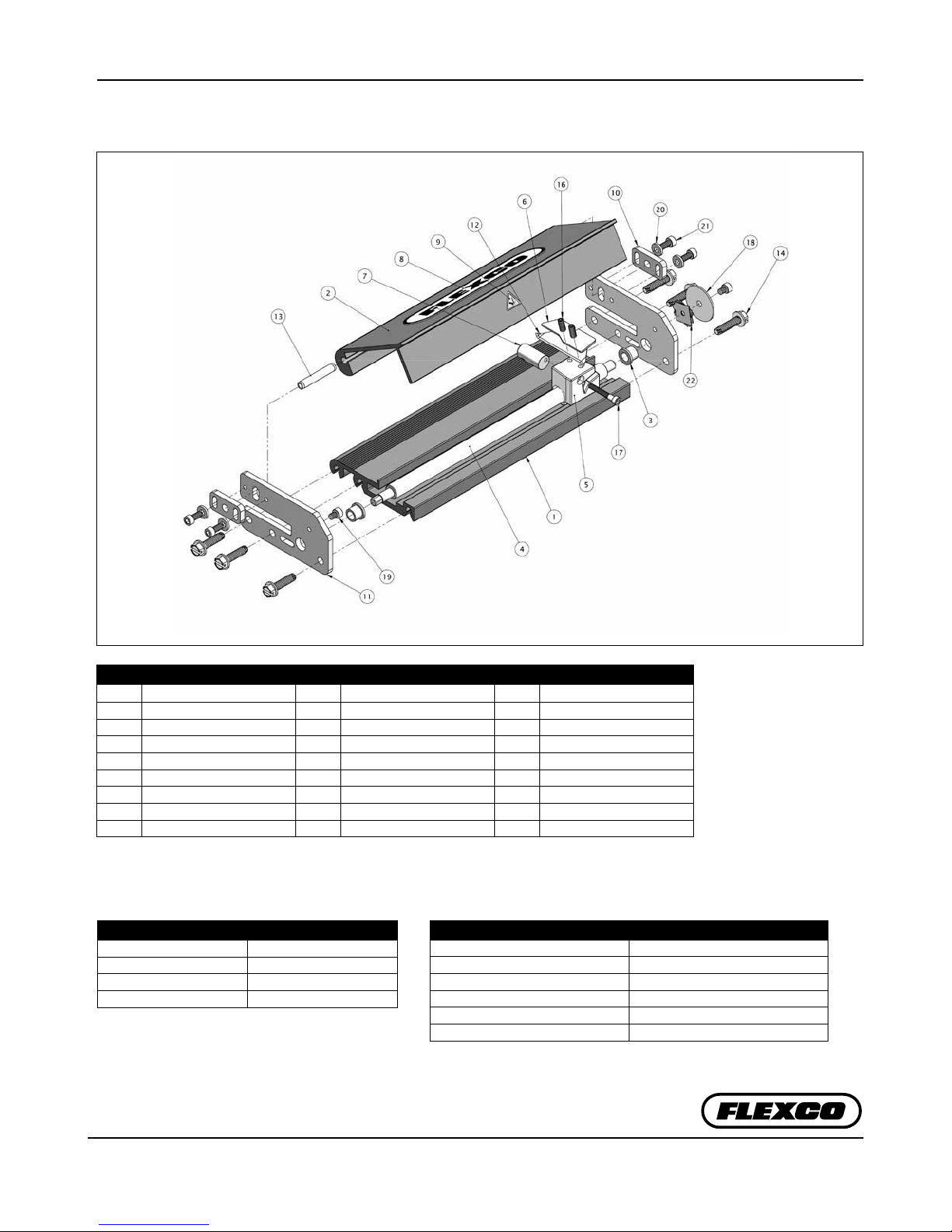
Main Components
Parts
Item Description Item Description Item Description
1 Base Plate 8 Flexco Label 15 Position Pins (not pictured) (2)
2 Clamping Lid 9 Cut Hazard Decal 16 Blade Set Screws (2)
3 Spindle Bushings (2) 10 Adjuster Plates (2) 17 Shaft Screw
4 Spindle 11 Side Plates (2) 18 Shim Storage Cover
5 Blade Holder 12 Blade 19 Shim Storage/Stop Screws (2)
6 Blade Backer Plate 13 Lid Hinge Pins (2) 20 Clamp Adjusting Washers (4)
7 Hold-Down Shaft 14 Base Screws (6) 21 Clamp Adjusting Screws (4)
22 Shims (5)
Tool Specifications
Tool Specifications
Maximum Belt Width 7.5 inches
Unskived Belt Thickness Range 0.200 to 0.400 inches
Skive Depth (Reach Back) 1.0 inches
Skived Belt Thickness Range 0.190 to 0.240 inches
Note: Other skived belt thicknesses may be achieved by providing
a shim beneath the belt.
Material
Side Plates, Blade Holder, Adjuster Plates Zinc-Plated Steel
Blade Backer Plate Stainless Steel
Lid and Base Hard Coat Anodized Aluminum
Spindle, Blades Steel
Spindle Bushings Bronze
Shims Polyester
—3—
Page 4
Adjust the Clamping Lid
A
!
WARNING
For best results: Store skiver in a clean dry area. Do not throw or drop tool.
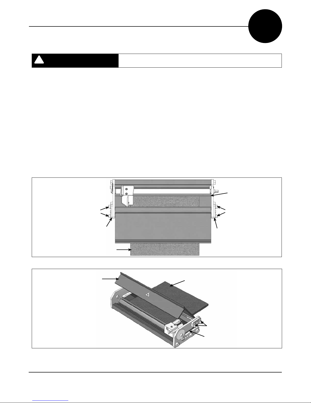
1. Using the 5/32" hex key (included) loosen the four clamp adjusting screws at the adjuster plates (Fig. 1).
2. Insert belt to be skived, positioning it at against the belt stop.
3. Hold lid at 45° angle from the belt and apply downward pressure (Fig. 2).
4. Tighten four clamp adjusting screws and close lid.
5. Clamping pressure is correct when clamped belt cannot easily be pulled from skiver and belt end to be skived
does not curl away from base when clamped (check for correct belt position by looking through slot of
sideplate).
6. If tighter clamping force is required, hold lid at between a 45 and 90° angle while applying downward pressure
and tighten screws.
7. Remove belt from skiver.
Keep ngers and hands away from blade cutting edge.
Belt Stop
Fig. 1
Fig. 2
Clamp Adjusting Screws
Adjuster Plate
Baler Belt
Clamping Lid
Clamp Adjusting Screws
Adjuster Plate
Baler Belt
Clamp Adjusting Screws
Side Plate
Slot
ww w.flexco.com
—4—
Page 5

Position Blade Holder, Belt and Hold-Down Shaft
Avoid contact with blade cutting edge.
!
CAUTION
1. Taking care not to touch the cutting blade, slide the blade holder to the right end of the spindle. (Fig. 3).
2. Using the 9/64" hex key (included) loosen the sha screw and rotate the sha to its maximum belt clearance
position. Temporarily tighten the sha screw.
3. Insert squared belt end into skiver ensuring that it is butted against the belt stop.
4. Position the belt so that the edge is against the cutting blade (Fig. 4).
5. Loosen the sha screw, insert suitable tool into sha adjustment hole (Fig. 3) and rotate sha to the le
(away) from the blade. Hold it against the belt surface with light pressure.
6. Tighten the sha screw.
7. Push on the position pin (Fig. 3) to engage blade holder and spindle. e position pin is also an aid in determining the location of the blade holder.
8. Close lid.
Before operation ensure spindle threads are free of dirt/debris to allow proper function of
blade holder release system.
B
Fig. 3
Fig. 4
LEFT
Belt Stop
Spindle Hex
Drive
RIGHT
Hold Down Shaft
Shaft Adjustment
Hole
Cutting Blade
Position Pin
Blade Holder
Blade Set Screws
Shaft Set Screw
Belt Edge Against
Cutting Blade
Spindle Threads
—5—
Page 6

C
Test Skive
For multiple skives, use of power drill is recommended to avoid fatigue from use of ratchet.
Operate only with clamping lid in place and fully closed.
!
CAUTION
1. Keep hand on closed lid to ensure adequate clamping force and to hold the skiver in place while skiving.
2. Use a hand-held power drill with a 1/4" extra deep bit on the spindle hex drive to rotate the spindle and skive the
belt (Fig. 4). A ratchet can be used in place of the drill.
3. Position the belt so that the edge is against the cutting blade (Fig. 4)
4. Measure the skived belt thickness.
5. Using the 3/32" hex key loosen blade set screws on top of blade holder.
6. Using the 5/32" hex key remove the shim screw and shim storage cover located on the right side plate to access the
shims(Fig. 5).
7. Insert the required number of shims under the blade to prevent belt carcass damage. Each shim is 0.010" thick, so
addition of each shim will result in the skived belt thickness being 0.010" thicker.
8. Tighten blade set screws.
Use hand drill with a clutch mechanism set to the minimum required to skive the belt.
Do not exceed 600 rpm when skiving.
Do not permanently ax a motorized drive device to this equipment.
Fig. 5
Shim Storage Screw
Shim Storage Cover
Right Side Plate
ww w.flexco.com
—6—
Page 7

Skive the Belt
1. Disengage the blade holder from the spindle and slide it to the right end of the spindle. Ensure blade holder
moves freely on spindle. Clean spindle if binding or grinding occurs.
2. Insert squared belt end into skiver ensuring that it is butted against the belt stop.
3. Position the belt so that the edge is against the cutting blade.
4. Close lid.
5. e clamping action may move the belt away from the belt stop. Verify that belt is against the stop by looking
though the slot of the side plate.
6. Using the hand drill, skive the belt.
7. Li lid and remove belt.
8. Measure the skived height to verify proper belt thickness for your fastener.
NOTE: Between skives, keep the interior of the base and the slot that guides the block free from belt material
and dirt. Store skiver with hold down sha in position to aid in guarding blade edge.
D
E
—7—
Page 8

Changing the Blade
E
!
WARNING
1. Loosen the blade set screws.
2. Carefully remove the blade and backing plate from the blade holder leaving the shims in place.
3. Insert a new blade on top of the previously installed shims. Ensure that the slot in the blade is seated around
the pin on the blade holder. When properly installed, the opposite end of the blade farthest from the belt is
seated and is completely recessed in the blade holder.
4. Replace the backing plate on top of blade ensuring that the slot is seated around the blade holder pin.
5. Replace shims under blade.
6. Tighten blade set screws.
7. Carefully dispose of old blade.
Backing
Plate
Keep ngers and hands away from blade cutting edge.
Blade
ww w.flexco.com
Correct Notch
Blade Holder Pin
—8—
Page 9

F
Maintenance
• Store blade adjusting shims behind shim storage plate when not in use.
• Lubricate spindle threads frequently. Spindle threads are initially coated with a semi-dry graphite / molybdenum
grease. Application of a high pressure molybdenum grease every 20 skives is recommended. It is also
recommended to lubricate the base blade holder surfaces shown (see image). For eld applications, use a hard
wax or other high pressure dry lubricant on threads and base blade holder surfaces, to avoid entrapment of dirt.
• If the skiver is used outdoors in eld applications, remove dirt from belt end and from skiver threads, blade and
blade holder rubbing surfaces. Dirt / grit will reduce blade and skiver life.
Lubrication Locations
Spindle Threads
Lubrication Locations
Blade Holder
Guide Slot
Blade Holder
Bearing Surface
—9—
Page 10

Troubleshooting
Symptom Possible Cause Possible Solution
Blade holder does not engage
with spindle threads
Belt moves during skive Inadequate clamping force
Inconsistent skive thickness
Carcass exposed
Inadequate skived belt thickness Shim selection
Inadequate skive depth (reach back)
Flap not separated down belt length
Flap not completely removed at skive end Normal Remove manually
Blade holder binding during skive
Blade holder does not release at end of
skive
Belt not positioned against blade
and hold down shaft
Blade holder beyond spindle threads Use position pin to aid engagement
Hold down shaft too tight or too loose
Blade dull Replace with new blade
Blade backing plate damaged or missing Replace blade backing plate
Shim selection
Blade dull Replace with new blade
Blade positioned incorrectly
Belt moved during skive Increase clamp force.
Belt too thick Remove with utility knife
Blade tip damaged Replace with new blade
Dirt present on spindle threads or blade
holder bearing surfaces
Blade dull Replace with new blade
Blade positioned incorrectly
Dirt or debris interfering with movement of
blade holder
Worn spindle or blade holder threads
Reposition belt
Readjust clamping lid for increased
clampforce
Loosen shaft screw and reposition hold
down shaft. Retighten screw
Add shim(s) to increase skived belt
thickness
Add or remove shim(s) to achieve desired
thickness
Ensure that blade is properly positioned
on the blade holder pin
Clean dirt from skiver and re-lubricate as
necessary
Ensure that blade is properly positioned
on the blade holder pin
Clean dirt and debris from skiver
Check threads for wear. Replace spindle
or blade holder as required.
G
ww w.flexco.com
—10—
Page 11

Replacement Parts
H
5
1
4
3
4
2
3
4
4
Replacement Parts List
Item Description Ordering Number Item Code
1 5 replacement blades BLADE-KIT-5-BALER-SKIVER 04990
2 5 replacement shims SHIM-KIT-5-BALER-SKIVER 04991
3 Spindle and 2 bushings SPINDLE-BALER-SKIVER-7IN 04992
Blade holder, hold-down shaft & set
4
screws, blade set screws
5 Blade backer BLADE-BACKER-SKIVER 04998
6 Bench mounting kit BENCH-MOUNT-KIT-BALER-SKIVER 04994
BLADE-HOLDER-KIT-BALER-SKIVER 04993
6
—11—
Page 12

2525 Wisconsin Avenue • Downers Grove, IL 60515-4200 U.S.A.
Telephone: (630)-971-0150 • Fax: (630)-971-1180 • E-mail: info@exco.com
Visit www.flexco.com for other Flexco locations and products.
©2016 Flexible Steel Lacing Company. 04-20-16. For reorder: X4138
 Loading...