

Page 1
Alligator® Light-Duty Belt Splicing
Training Manual
LIGHT-DUTY BELT FASTENER SYSTEMS
Page 2
LIGHT-DUTY BELT FASTENER SYSTEMS
Table of Contents
Proper Belt End Preparation .............................................................. 3
Alligator® Ready Set™ Staple Belt Fasteners
Overview............................................................................................................. 4
Installation Tools ................................................................................................. 5
Installation Accessories ...................................................................................... 6
Identifying a Properly Installed Alligator Ready Set Splice ................................. 7
Troubleshooting ............................................................................................... 8-9
Tips ..................................................................................................................... 9
Alligator® Lacing
Overview........................................................................................................... 10
Identifying a Properly Installed Alligator Lacing Splice ......................................11
Troubleshooting .................................................................................................11
Alligator® Rivet Baler Fasteners
Overview........................................................................................................... 12
Identifying a Properly Installed Alligator Rivet Splice........................................ 13
Troubleshooting ................................................................................................ 13
Tips ................................................................................................................... 13
Alligator® Non-Metallic Splicing
Overview........................................................................................................... 14
Identifying a Properly Installed Alligator Plastic Rivet Splice ............................ 14
Troubleshooting ................................................................................................ 15
Tips ................................................................................................................... 15
2
Page 3
Proper Belt End Preparation
Importance of a Square Cut
To prevent mistracking and extend splice life, it is critical to obtain a square cut
off from the centerline of the belt. To achieve this, follow these simple steps:
1. Prior to any work on your conveyors, make certain that the power has been
turned off and the belt is “locked out”.
2. Using a diagonal measurement that is approximately 6" (150 mm) wider than
the belt width, mark the center point of the measurement every 3 to 5 feet down
the length of the belt, for a distance of 15 to 20 feet. Tip: Use a number that is
easily divisible by two for your diagonal measurement. Any even number that is
approximately 6" (150 mm) or wider than the belt width can be used (Fig. A).
3 Using either a steel rule or a chalk line, mark the average centerline across the
belt width (Fig. B).
4. Using a square, draw a line perpendicular to the average centerline across the
belt width (Fig. B).
5. Cut the belt using the Clipper
the cutter.
48" (1200 mm)
Diagonal Measure
®
845LD Belt Cutter, following the instructions for
LIGHT-DUTY BELT FASTENER SYSTEMS
Midpoint
24" (600 mm)
42" Belt
(1060 mm)
Skive Impression Cover Before Fastener Installation
It is important to skive off the impression cover of a belt in the area
where fasteners will be applied. This allows the proper size fastener
to be selected and for proper penetration/clinch. Two tools are
available to assist in this process:
Rough Top Belt Skiver
This simple-to-use, hand-held tool skives off the
impression cover when pushed along the belt cover.
RB-1 Belt Grinder
This air-drill attachable tool is made with carbide to cut the
impression cover off the belt. Most standard grinders burn
the impression cover off, which heats and damages the
belt carcass, resulting in shorter splice life.
3
Page 4
ALLIGATOR
Alligator® Staple Overview
Advantages of Alligator® Ready Set™ Staple Fastening System:
• High strength splice
• Inexpensive, portable installation tool
• Easy to mesh lacing and insert pin
®
STAPLE
Two Styles of Alligator Staple Fasteners:
Ready Set™: Available in Steel, 430 Stainless Steel and 316 Stainless Steel. Ready Set
Staple Fasteners feature a one-piece fastener strip with pre-inserted staples, reducing
installation time by eliminating the need to handle and load individual staples. The result
is a strong splice that resists impact damage, as well as a smooth, unrippled joint
to simplify hinge pin insertion.
• Abrasion resistant splice
• Easy installation procedures
Conventional Staple Fasteners: Available in abrasion resistant MegAlloy®, providing
several times the service life of steel. Staples are separate from the fastener plates.
Green guide blocks (ST4-5) must be installed on the installation tool and users can insert
staples using the C150 staple dispenser.
ALLIGATOR® READY SET™ STAPLE
Fastener
Size
RS62 100 17 1/16-1/8 1.5-3.2 2 50 nylon .080, steel .080 nylon 2.0, steel 2.0
RS125 160 28 1/8-3/16 3.2-4.8 3 75 nylon .141, steel .141 nylon 3.6, steel 3.6
RS187 200 35 3/16-1/4 4.8-6.4 4 100 nylon .203, steel .187 nylon 5.2, steel 4.7
Operating
Tension Range
P.I.W. kN/m in. mm in. mm in. (nylon-steel) mm (nylon-steel)
Belt Thickness
Range
Minimum
Pulley Diameter
Approximate Hinge Pin Diameter
METAL SELECTION CHART
Metal Type Application
Steel Standard fastener material suitable for most applications. Plated for
316 Stainless Steel Extra resistance to abrasion, magnetic attraction, and corrosion
430 Magnetic
Stainless Steel
MegAlloy
®
rust and corrosion resistance.
from acids and chemicals. Excellent for high sanitary requirements.
For use with magnetic separators. Provides resistance to wear and
abrasion. Plate, staples, and hinge pins are all constructed from
magnetic stainless steel.
Superior resistance to wear and abrasion, providing several times
the service life of steel. Not recommended where subject to impact
or corrosion. Not available in the Ready Set conguration.
4
Page 5
Alligator® Staple
Installation Tools
Alligator® RSC187 Installation Tool
The RSC187 Installation Tool securely holds
fasteners in proper alignment and guides
staples as they are driven. Installs two staples
simultaneously for fast and simple splicing.
Also provides a solid anvil surface for initial
staple clinching.
The RSC187 comes complete with a driver
and guide blocks for all three fastener sizes.
Also available in sizes to match a variety of belt
widths; wider tools are available for production
lacing and fabrication shop requirements.
ALLIGATOR
®
STAPLE
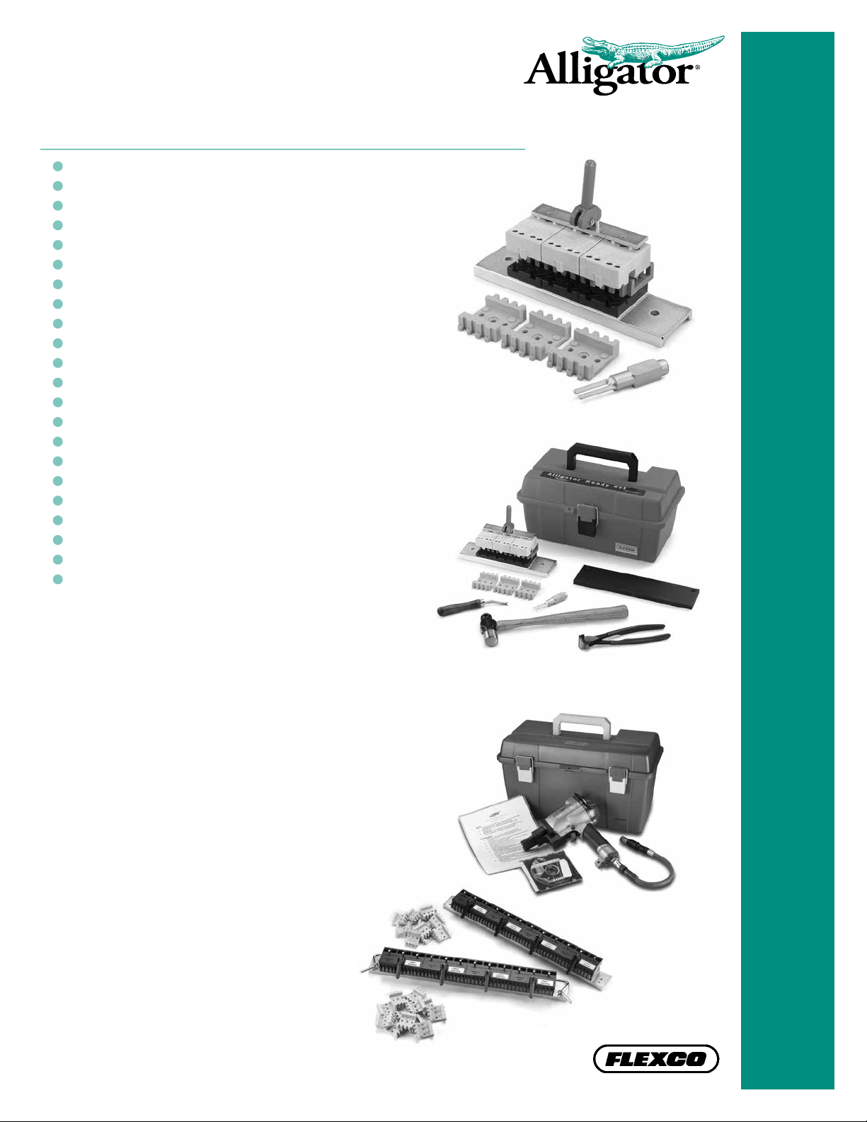
Alligator® Staple Tool Kit
Everything needed to install Alligator® Ready
Set™ Fastener Systems, in a lightweight, easyto-carry toolbox. Includes a RSC187 Installation
Tool, ST3-9 Staple Driver, SR-28 Staple Set
Plate, RTBS Rough Top Belt Skiver, BN-1 belt
nippers, and 1-lb. hammer.
Alligator® Staple
Gold Class™ Power Driver*
The air-operated Power Driver* allows
belt fabricators to install Alligator
Set™ Staple plates with quick and effortless
trigger pulls. This simple installation
process allows for splices to be installed
quickly and consistently, regardless of
operator skill and experience.
By eliminating the need to hammerinstall the fasteners, the Alligator
Staple Gold Class tool reduces the
risk of repetitive motion injuries.
It also reduces operator fatigue
associated with hammer-installing
numerous splices throughout the day.
®
Ready
*Patent pending
5
Page 6

ALLIGATOR
Alligator® Staple
Installation Accessories
Staple Setting Plate (ST-28)
Final set of the staples and proper compression of the
fastener plate are necessary for long splice life. The heattreated steel setting plate provides the required hardened
surface to achieve a properly installed splice. The ST-28
also features countersunk bolt holes for mounting onto a
work surface.
®
STAPLE
Alligator® Hinge Pin Cutter (APC-1)
Cuts bulk hinge pin cable quickly and easily. Provides a
clean cut with no frayed ends.
Hinge Pin Retaining Washers
Retaining washers prevent migration of nylon-covered cable
hinge pins. Check hinge pins frequently during the rst few
hours of operation to determine whether migration is a problem
in your application; use retaining washers if necessary.
Hinge Pin Bender (PB1)
For use with steel spring wire pin. Bends hinge pin end to
prevent pin migration.
Rough-Top Belt Skiver (RTBS)
Durable, hand-operated tool for quick and clean removal of
rough top from light- and medium-duty conveyor belting.
Belt Nippers (BN-1)
A simple, hand-held tool used to notch/chamfer belt edges
and to remove individual fastener plates from belt.
6
Page 7

Identifying a Properly
Installed Alligator® Ready Set™ Splice
1. Staples should be completely driven through and properly
set into pockets on bottom side of fastener plates.
Incorrect Correct
2. There should be a slight puckering of the belt at the front
edge of the top plate. On belts with very hard top covers,
or no top cover, this may not always be possible.
3. Fastener plates should be rmly compressed onto belt
and you should not be able to catch your ngernail under
front edge of fastener plate.
ALLIGATOR
®
STAPLE
4. Loops have not been crushed. Hinge pin insertion is easy.
5. Belt is ush against fastener belt stops across width of belt;
fasteners are parallel with belt edge.
6. Corners on trailing end of belt have been notched/chamfered.
7. Pin Retaining Washers, if used, are properly crimped.
Direction of
Travel
Chamfer
trailing edge
7
Page 8

ALLIGATOR
Troubleshooting
®
STAPLE
The Fastener Plates Are Loose:
Fasteners were not fully set.
• Fasteners should be rmly set, creating a slight puckering
of belt around front edge of top plate. This may not be
possible on hard belts or belts with little top cover.
• You should not be able to catch a ngernail under plates.
• Belt is either too thin or too thick for size of Alligator® Staple fastener selected.
Conrm proper size has been selected.
• Rough top belt was either not skived or the belt was skived too thin for the size
of Alligator Staple fastener being used.
‘Final Set’ procedure was performed on a surface other than a hardened steel plate.
• A hardened steel plate, such as the Flexco ST-28 setting plate, should be used.
Surfaces such as soft steel or wood will not allow staples to be fully set and/or
can cause staple leg to deect out of the pocket.
‘Final Set’ procedure was performed from bottom side of the
fastener, causing staples to back out or to buckle inside of
the belt.
• Final setting of staples should always be performed
from top side of fastener on a hardened steel plate.
The Staples Misre During Installation:
Either too heavy a hammer or the wrong type of hammer was used.
• A 1-lb. hammer is recommended with the standard Staple Driver.
• A 2-lb. hammer is recommended with the Quad Staple Driver™.
• A dead blow, soft steel or rubber hammer should not be used.
Initial hit with the hammer was too hard.
• Starting with a moderate blow, hit driver with three to ve consecutive
blows, each blow harder than the previous one.
®
Anvils in the Alligator
• Inspect for deep/worn pockets and chipped/worn
walls in angled areas of the anvils.
• Check alignment of guide block posts.
RSC187 Tool are worn or broken.
A mild steel plate was used for ‘Final Set’ procedure.
• Use only a hardened steel plate, such as the Flexco
ST-28, when performing the ‘Final Set’ procedure of
the Ready Set fasteners.
8
Page 9

Troubleshooting (cont.)
The Fasteners Are Not Flush and Parallel With Belt Edge:
Belt was not installed ush against the Ready Set fastener belt stops.
ALLIGATOR
Fasteners were installed from ‘left to right’ or ‘right to left’.
• First install the center two fasteners and then install
fasteners on outside edges. Finish by installing the
remaining fasteners.
Cam levers were not properly engaged or are worn.
• Tighten cam lever by turning it clockwise until a snug lock is achieved.
• Replace cam levers.
Spring-loaded belt nails located in top block of the Alligator RSC187 are stuck or
are missing. Replace top block as needed.
Tips
• Procedure for removing an Alligator
In the event of a misred staple there may be the need to remove a single
Staple fastener plate from the laced belt end. To do so:
1. Using the Flexco Belt Nippers, cut the back side of both loops on the
fastener to be removed.
2. Use the Belt Nippers pull the top plate off. This will take some effort
because the staples will need to be pulled straight.
3. Break the bottom plate free from the adjoining fasteners by exing the
belt back and forth at one of the two scores on the bottom plate.
4. With one score broken, use the Belt Nippers to ex the loose plate at
the remaining score to break the bottom plate free.
5. Remove a single Staple fastener plate from a new fastener strip by
exing an end fastener at the score until it breaks off.
6. Install the single fastener plate using the RSC187 installation tool and
a standard two-pronged driver.
®
Staple fastener from a laced belt end
Correct
®
STAPLE
• Alligator RSC187 Installation Tools that are 12" (300 mm)
or wider are designed with a Belt Release Bar. Use a
light hammer blow on the ends of the Belt Release Bar to
disengage the Ready Set fasteners from the tool.
• If you are not sure of the direction of belt travel,
notch/chamfer all four corners.
9
Page 10

ALLIGATOR
Alligator® Lacing Overview
Advantages of the Alligator® Lacing System:
• Low prole
• Hammer applied; Does not require special installation tools
• Can be installed in the Clipper
with appropriate combs, if so desired.
®
Roller Lacer® and Pro Lacers
®
LACING
Two Styles of Alligator Lacing:
Conveyor Belt Lacing: Features a “radius check” reference point
to aid in trimming strips for narrower belt widths.
Transmission Lacing: For at power transmission belts up to
12" (300 mm) wide. Lacing is scored, so it can break away to
custom-t belts narrower than the packaged fastener length.
ALLIGATOR® LACING SELECTION CHART
Lacing
Size
00 25 4.3 up thru 1/16 up thru 1.6 1 25 3/64 1.2
1 45 7.8 1/16–3/32 1.6–2.4 1-1/2 38 1/16 1.6
7 50 8.7 3/32–9/64 2.4–3.6 2 51 1/16 1.6
15 65 11.4 1/8–5/32 3.2–4.0 2-1/2 64 3/32 2.4
20 95 16.6 5/32–3/16 4.0–4.8 3 76 7/64 2.8
25 100 17.5 3/16–7/32 4.8–5.6 4 102 1/8 3.2
27 100 17.5 7/32–9/32 5.6–7.1 5 127 1/8 3.2
35 150 26 9/32–5/16 7.1–7.9 7 178 9/64 3.6
45 165 28 5/16–3/8 7.9–9.5 9 229 3/16 4.8
55 175 30 3/8–7/16 9.5–11.1 12 305 13/64 5.2
65 200 35 7/16–1/2 11.1–12.7 14 356 13/64 5.2
Radius Check
Score
For Belts with
Mechanical Fastener
Ratings Up To:
P.I.W. kN/m in. mm in. mm in. mm
Belt Thickness Range
Minimum Pulley
Diameter
Corrugated
Hinge Pin Diameter
METAL SELECTION CHART
Metal Type Application
Steel Suitable for most applications.
316 Stainless
Steel
Sizes 00, 1, and 7 are plated for
rust and corrosion resistance.
Provides extra resistance to
abrasion, magnetic attraction,
and corrosion from acids and
chemicals. Also excellent for
high sanitary requirements.
10
PIN SELECTION CHART
Metal Type Application
Corrugated Steel
or Stainless Steel
Nylon Covered
Steel or Stainless
Cable
Steel or Stainless
Steel Rocker Pins
Rigid pin with corrugation to prevent pin from
migrating out of the splice.
Available in coil lengths. Ideal for applications
with crowned pulleys or with troughing idlers.
Used with Transmission Lacing. Two-piece
design creates a rocking action to reduce
wear and friction on the fastener loops.
Furnished with Transmission Belt Lacing sizes
15 - 65. Corrugated pins are furnished with
Transmission Belt Lacing sizes 00, 1 and 7.
Page 11

Identifying a Properly
®
Installed Alligator
Lacing should be ush with belt surface.
1.
2. Points should slightly penetrate opposite side of belt.
3. Loops of lacing should not be crushed and will easily
accept the hinge pin.
Lacing Splice
3
Troubleshooting
Lacing Teeth Do Not Fully Penetrate Belt and Clinch Over
ALLIGATOR
1
2
®
LACING
Be sure to use a soft piece of wood under the fastener when rst applying lacing. This
allows the teeth to fully penetrate the belt.
Ensure the following installation procedures have been followed. NOTE: Steps 1-4 are
performed using the soft piece of wood as a backing plate.
1. From top side of belt, install end two teeth on both belt edges halfway in.
2. Flip belt over and install fastener teeth on bottom side of belt halfway in
across entire splice width.
3. Flip belt back over and nish installing remaining teeth on top side of belt.
4. Repeat on bottom side of belt.
5. Use a hardened steel plate and nal set the lacing.
Hinge Pin is Difcult to Insert
Be sure to use gauge pin and clips when applying Alligator Lacing. This will ensure a
uniform loop across the entire width.
Loops may have been crushed with direct hammer blows. Use caution when installing
fasteners and do not hit the loops.
Failure to follow proper lacing installation sequence as described above in Steps 1-5 can
cause points on non-bar side of lacing to wander and not penetrate correctly. This can
cause a distortion in the loop area, making pin insertion very difcult.
11
Page 12

ALLIGATOR
Alligator® Rivet
Baler Fastener Overview
Advantages of Alligator® Rivet Fastener System:
• High strength splice
• Superior abrasion resistance
• Portable tool allows for on-site installation
• Easy installation
• Fasteners are available in pre-cut common baler belt widths
®
RIVET
ALLIGATOR® RIVET SPECIFICATION CHART
Operating Tension
P.I.W. kN/m in. mm in. mm in. mm
300 52 1/8 – 7/32 3.2 – 5.6 3-1/2 88 .140 3.6
Application Tools and Accessories:
Hand Applicator Tool: Available in 7" and 14" widths.
Portable for on-site installation. Tool has built-in belt stops
to prevent belt from entering fastener loop area. Belt clamp
secures belt during installation process.
Multiple Rivet Installation Tool: Available in 7" and 14"
widths. This tool is comprised of a Hand Applicator Tool
plus the Multiple Rivet Installation block. Users can install
rivets with either a hammer and hand-punch, or with an
air hammer and pneumatic punch. Simplies installation
procedure and reduces fatigue.
Range
Belt Thickness Range Pulley Diameter Hinge Pin Diameter
Identifying a Properly
Installed Alligator® Rivet Splice
1. Fasteners should be fully clinched and you
should not be able to catch your ngernail
under the front edge of the fastener plates.
NOTE: Using the Alligator Rivet Application
Gauge can help to insure fasteners are
properly set. Finished splice should t into
the “Maximum Finished Rivet Height” slot
in the gauge.
2. There should be a slight puckering of the
belt at the front edge of the top plates.
12
Page 13

Identifying a Properly
Installed Alligator® Rivet Splice
(continued)
3. Rivets should be fully set and curled on bottom side of splice.
4. Loop area of fastener is oval in shape and easily accepts
the hinge pin.
ALLIGATOR
5. Fasteners are inset 1/4" (6.4 mm) from each belt edge.
6. Corners of trailing end of belt have been notched/chamfered.
Troubleshooting
Direction of Travel
Fasteners Are Loose
Fasteners were not fully set when applied.
• You may be able to reinsert splice into the ART tool and reset with a hammer.
If you attempt to reinsert splice into the ART tool, make sure you have left
Pilot Nails in tool so rivets properly curl.
Belt was not skived to remove rough top or diamond top impression cover.
Belt was skived too thin for Alligator Rivet fasteners.
• Use Alligator Rivet Application Gauge to double-check acceptable
skived belt thickness.
®
RIVET
Belt Edges Do Not Line Up
Align belt edges with appropriate scribe marks on ART tool
based on your belt width.
Tips
• You may nd it easier to join splices together by laying
one laced belt end over the other belt and pressing them
together versus trying to mesh them end to end.
• Hitting center of belt directly behind ART tool helps to
release Pilot Nails, making it easier to remove laced belt
from the tool.
13
Page 14

ALLIGATOR
Alligator® Non-Metallic
Splicing Overview
Advantages of Alligator® Non-Metallic Splices:
• Non-metallic
• Non-magnetic
• Non-sparking
• Quiet
• Hinged splice; quicker installation on conveyor system.
• Compatible with X ray machines, metal detectors, and
®
food applications
NON-METALLIC SPLICING
Two styles of Alligator Non-Metallic Fasteners:
Alligator® Spiral Lace: Low-prole, non-metallic splice that
is compatible with pulleys as small as 1/2” (13 mm) and for
applications up to 50 PIW (8.7 kN/m). Splice is fabricated
into belt through a ply separation, ply step, or nger splice
vulcanization processes. Available in black or white polyester,
or in PEEK for high heat applications.
Alligator® Plastic Rivet: One-piece, cover-mounted fastener
features an integrated design with rivets molded into the
fastener top plate. Fastener edge is beveled to ensure
smooth transition and easy cleaning. Fasteners are installed
with the Alligator Spin Set Tool™. This portable tool allows for
simple installation anywhere in your facility.
APF FASTENER
Identifying a Properly Installed
Alligator® Plastic Rivet Splice
1. Fastener plates are ush against belt and you cannot catch
a ngernail under the front edge of the fastener plate.
2. Rivets have been fully compressed and melted into a nice
dome shape.
3. Corners have been notched/chamfered on trailing end of belt.
MDT-1
14
Page 15

Troubleshooting
Fasteners Are Loose
Plastic rivets may not have been fully compressed during installation.
Alligator Plastic Rivet Lube was not used during
installation of the fasteners.
• Using lube allows plastic rivets to melt at the
proper speed and helps to control heat generated
during the installation/melting process.
The Rivets Loosen or Break When In Service
Rivets may have been overheated during installation process.
• Be sure to use Alligator Plastic Rivet Lube when compressing/melting plastic
rivets to avoid overheating plastic and making it brittle.
ALLIGATOR
®
NON-METALLIC SPLICING
Conveyor tension exceeds recommended tension for this fastener.
15
Page 16

2525 Wisconsin Avenue • Downers Grove, IL 60515-4200 • USA
Tel: (630) 971-0150 • Fax: (630) 971-1180 • E-mail: info@exco.com
Visit www.flexco.com for other Flexco locations and products.
©2009 Alligator®, Clipper® and Roller Lacer® are registered trademarks. 02-14. For Reorder: X1385
 Loading...