

MANUAL
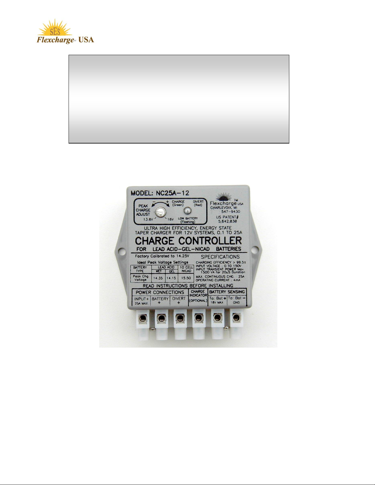
MODEL: NC25A-12(24, 36, 48)
Ultra High Efficiency
25 Ampere Alternative Energy Battery
Charge Controller
For GEL, AGM, and Flooded Cell Lead Acid Batteries
Not for Lithium Batteries
SES Flexcharge USA, 1217 State St., Charlevoix, MI 49720
Ph: 231-547-9430, Web Site: www.flexcharge.com
12V Controller Shown Below
Patented
Rev 04, Ver1
AUG 2018
Page 1 of 24

IMPORTANT INFORMATION
Table Of Contents
Page
Contents
1
Cover
2
Table Of Contents
3
Features
4
Controls and Indicators
5
Installation Instructions
7
Indicator Functional Description
8
Flexcharge Energy State Charge Method (ESCM)
9
Operating Characteristics - Wire Selection Chart - Diode Selection Chart
10
Using or Not Using Blocking Diodes
11
Solar Panels Charging One Battery Bank
12
Solar Panels Charging Two Battery Banks
13
Wind/Water Generator Charging One Battery Bank
14
Wind/Water Generator Charging Two Battery Banks
15
Solar with Wind/Water Generator Charging One Battery Bank
16
Solar with Wind/Water Generator Charging Two Battery Banks
17
Charging Two Battery Banks Using a Selector Switch
18
Charging Two Battery Banks Using an A/B Battery Switch (Not Recommended)
19
Charging From Smaller Outboard Motors
20
Expanding the NC25A to Regulate High Ampere Charging Sources
21
Troubleshooting Guide
22
Charging Efficiency Graphs
23
General Guidelines for Designing Your System, and Warranty Information
THE NC25 CONTROLLER IS AN "ON/OFF" REGULATOR NOT A CONSTANT VOLTAGE
REGULATOR, AND THEREFORE IT CANNOT BE TESTED BY SIMPLY MEASURING THE OUTPUT
VOLTAGE ON THE TERMINAL STRIP OF THE CONTROLLER. THE CONTROLLER MUST BE
CONNECTED AS SHOWN IN ONE OF THE SCHEMATICS BEFORE IT WILL REGULATE.
READ ALL OF PAGES 5 through 8 OF THIS MANUAL TO LEARN HOW THE CONTROLLER
REGULATES BEFORE CONCLUDING THAT YOUR CONTROLLER IS NOT REGULATING.
All wire to wire and crimp connections must be
soldered for this, or any charge controller to
operate dependably.
Do not solder on the controllers terminal block.
The terminals on the controller are coated with an
anti corrosion coating.
Page 2 of 24

Features
Use Flooded Cell Battery settings for all AGM type batteries.
* 5 YEAR WARRANTY.
* COMPLETELY SEALED ELECTRONICS FOR MARINE OR OUTDOOR MOUNTING.
* LOW BATTERY VOLTAGE INDICATOR. (FLASHING RED LIGHT).
* Works with GEL, AGM, and Flooded Cell Lead Acid Batteries. Also for flooded Ni-Cad Batteries
* ARC REDUCTION CIRCUITRY TO ELIMINATE OR REDUCE RELAY CONTACT WEAR.
* CHARGING EFFICIENCY BETTER THAN 99.50% FROM 0.5A TO 30A OF CHARGING CURRENT.
* OPERATES EFFICIENTLY (98%) WITH AS LITTLE AS 0.1A OF SOLAR PANEL CHARGING
* EFFICIENTLY CHARGES BATTERIES FROM 0 VOLTS WITH FULL POWER.
* No RFI or EMI emissions to interfere with radio or data logging equipment
* 25 AMP CHARGE CAPACITY. SPECIAL ORDER 24V, 36V, AND 48V MODELS, OR EXPANDED
* 25 AMP CHARGE DIVERT CIRCUIT. STABLE DIVERT CIRCUITRY PREVENTS ERATIC RELAY
* DIVERTS ONLY WHEN VOLTAGE AND CURRENT ARE AT USABLE LEVELS.
PERFECT FOR MOTOR TYPE DIVERT LOADS (FANS, PUMPS, etc...)
* PEAK CHARGE VOLTAGE ADJUSTMENT WITH A RANGE OF 13.8V TO 15.9V (Multiply by 2,3,or 4
* CHARGES WITH THE SAME HIGH ACCURACY VOLTAGE SENSING THROUGH BATTERY
* CONSUMES LESS THAN 5mA (0.005A) WHILE CHARGING AND AT NIGHT, 2mA IF YOU DO NOT
* CHARGES BATTERIES AT FULL POWER, BELOW THE PLATE SATURATION POINT, THIS
* BATTERIES START CHARGING AT 0.005A OF CHARGE CURRENT.
* CONTROLLER CAN WITHSTAND OPEN CIRCUIT INPUT SPIKES OF 1500VA, & 140V CONTINOUS
* REVERSE POLARITY AND TRANSIENT VOLTAGE PROTECTION ON THE BATTERY SENSE WIRES.
* NO POWER WASTING SAMPLE PERIODS.
* REMOTE BATTERY VOLTAGE SENSING SO THE CONTROLLER CAN BE MOUNTED ANYWHERE
* EASY TO INSTALL USING THE LABELED CORROSION RESISTANT NICKEL / BRASS / STAINLESS
* U/L 94V-O RATED ENCLOSURE AND UL LISTED OR RECOGNIZED COMPONENTS.
CURRENT.
MODELS WITH CHARGING CURRENT CAPACITIES UP TO 2000A.
SWITCHING IF CHARGE SOURCE VOLTAGE DROPS.
to determine voltages for 24V, 36V, or 48V versions).
ISOLATORS.
USE THE CHARGE INDICATOR.
CHARGES BATTERIES FASTER, AND REDUCES ELECTROLYTE DEPLETION BY UP TO 90% OVER
CONVENTIONAL CONSTANT VOLTAGE, PWM, & HIGH FREQUENCY CHARGE REGULATORS.
WITHOUT DAMAGE.
BETWEEN THE CHARGING SOURCE AND THE BATTERIES.
STEEL CONNECTOR.
Page 3 of 24
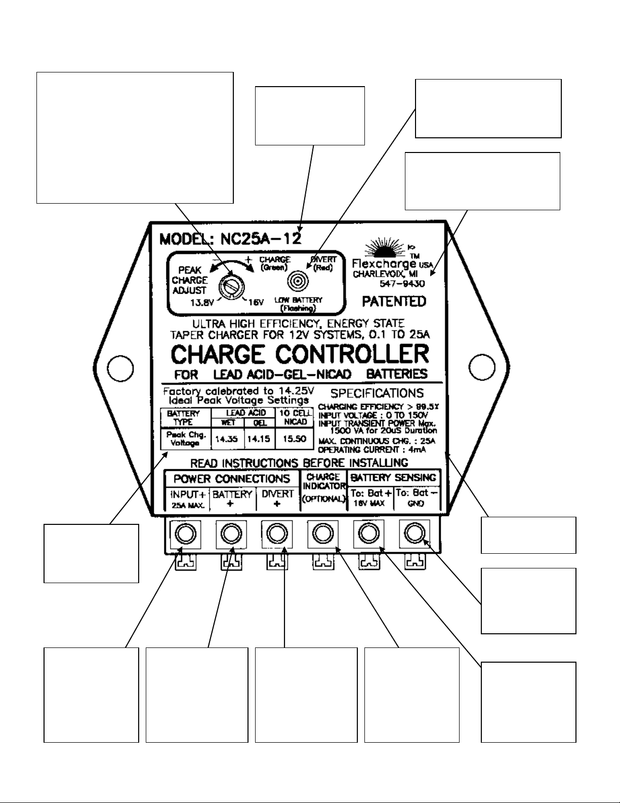
Peak Charge Voltage Adjustment
Factory Calibrated for use with Lead
acid and Gel and AGM Battery
Technologies. Look for the small
calibration dent in the case
Do not move this adjustment unless
you have special battery voltage
requirements.
Multi Function Indicator
See the table on page 7 for
description of operation
Call Direct to the
Manufacturer. Technical
Questions, Warranty info, etc
231-547-9430
System Voltage
12= 12V, 24=24V,
36=36V, etc
Charging Input
Connect the
Positive Wire
from the
Charging Source
here.
Controller Output
to Battery
Connect to Fuse
then to Battery +
Divert Output
Connect to a Fuse
then to Divert Load
Positive (Optional)
Quick Reference
for custom
voltage settings.
(Optional)
General
Specifications
CONNECT
DIRECTLY TO
THE BATTERY’S
NEGATIVE (-)
TERMINAL
See Installation
Drawings.
Using the charge
Indicator is
optional
CONNECT
DIRECTLY TO A
FUSE THEN TO
THE BATTERY’S
POSITIVE (+)
TERMINAL
231
Page 4 of 24
INSTALLATION INSTRUCTIONS
Flexcharge
TM
USA NC25A
ULTRA HIGH EFFICIENCY CHARGE CONTROLLER
Congratulations, you will soon be using the most efficient controller available. Using this
controller has the direct equivalency of increasing your solar panel capacity by up to 20% over
any other controller FlexchargeTM USA has examined. This controller is available with
capacities to 2000 amps with the same, or increased charging efficiencies.
NOTE: The NC25A does not contain any blocking diodes.
IMPORTANT: PLEASE READ THE SECTION "USING BLOCKING DIODES" Pg.10
Do not wire your solar panels in series for higher voltage output. Use the following voltages for best
performance. 12 volt systems. V peak power 15 VDC, 24 volt systems V peak power 30 VDC, 36 V
systems V peak power 45 VDC, 48 V systems 60 VDC. You can be up to 5 volts higher with no affect
but not lower. For example using a 100 watt panel with a peak power voltage of 30 volts on a 12 volt
system will only give you a charge rate of about 50 watts while a peak power voltage of 15 volts would
give you the full 100 watts.
1) Choose a good mounting location.
Even though the controller has been designed for mounting outside, mounting it in a more protected
environment will help to extend it's operational life.
2) Install the NEGATIVE BATTERY SENSE WIRE from the controller's terminal block to the
battery bank negative (-) terminal. You should use #16 to #14 awg black wire.
3) Install the POSITIVE BATTERY SENSE WIRE from the controller's terminal block to a 1A or 2A
fuse and then to the battery bank's positive (+) terminal. You should use #16 to #14 awg
yellow or red wire.
IMPROTANT
When installing the terminals on to the sense wires for connection to the battery, crimp then
solder the terminals to the wire. Make absolutely sure these wires make very good electrical and
mechanical connection with the battery's terminals. If either of this or the ground connections were to
loosen, or corrode, the controller will have no way to sense battery voltage, causing it to switch to a
non-regulating mode and overcharge the batteries. The sense wires may be extended up to 100 feet
using #14 or larger wire. All splice joints must be soldered. If you are charging multiple isolated battery
banks through a battery isolator, connect the SENSE wires to the primary (most used) battery bank.
The other batteries will follow the primary battery's voltage, and will not be over or under charged.
IMPORTANT
For the next four steps, see the Wire Size Table on page 9 to select the correct size wire for your
charging current and length of wire.
4) Connect the charging source negative (-) wire to the negative (-) terminal on the battery
and/or the system's negative battery bus. If you are using a smart battery fuel meter that
measurers total Input to Output Amp/Hours, it will usually have a shunt in the (-) connection to the
battery. Connect the (-) wire from the charging source to the shunt as shown in the meter’s manual.
5) Install the BATTERY POSITIVE (BAT. +) wire from the controller to the battery's positive
terminal. A fuse rated at 1.5 times larger than your maximum charging current, but less than
30A, should be installed in this wire near the battery. Remember to solder all wire connectors
even if they use crimped connectors.
Page 5 of 24

6) Connect the charging source (Solar, Wind, etc.) positive wire to the controller's INPUT+
terminal. CAUTION: IF THE SOLAR PANELS ARE EXPOSED TO LIGHT, THEY WILL BE
GENERATING POWER. WIND SYSTEMS SPINNING UNCONNECTED CAN HAVE VOLTAGES
ABOVE 100V. It is preferred to stop the generator from turning before connecting the wires from it.
There will be a spark when you attach this wire if the charging source is generating power, this may
be OK if it is not turning very fast but be sure you are not near any flammable fumes. Turn off the
source if possible.
7) DIVERT Feature. When installing a Divert Load, the following steps must also be followed.
You must use a properly sized Divert Load on wind and towed generator systems
a) Connect the Divert Load's negative (-) wire to the negative (-) terminal on the battery or the
system's negative battery bus. If you are using a smart battery fuel meter that measurers total
Input to Output Amp/Hours, it will usually have a shunt in the (-) connection to the battery. Connect
the (-) wire from the Divert Load to the battery (-) not to the shunt as shown in the meter’s manual.
b) Install a fuse rated at 1.5 times larger than your maximum charging current, but less than
30A, in the Divert wire near the controller's terminal block in the Divert Load's positive wire.
Choosing the right Divert Load
The Divert output from the controller is unregulated. This means that when the controller is in Divert
mode, this terminal is directly connected to the charging source, just as if there were no controller
installed. (i.e. The solar panels connected directly to the Divert Load) If the divert load draws less
current than the maximum charging current of your system, the load could burn up. The best rule of
thumb is; either use a Divert Load with a voltage rating twice that of your battery system, or one that
has the same voltage rating as the batteries but has a current rating equal to the maximum your system
can generate. See the Flexcharge Divert loads at www.flexcharge.com
8) CHARGE INDICATOR LIGHT. It is not necessary to use the Charge Indicator Light. If you wish
to use it, connect the CHARGE INDICATOR TERMINAL on the controller's terminal block, to one of
the charging source’s diodes, at the source end. For example; on a solar panel it would connect to
the solar panel end of the diode. See the wiring diagrams. In order to maintain the ultra high
charging efficiencies in the NC25A, it may not be feasible to use the charge indicator while charging
from outboard motors or on certain wind generators. If you have access to the blocking diode in the
charging source or you are charging through a dual battery isolator, then you can use the charge
indicator. A much more informative indication of charging is an amp meter installed into the Red
BAT+ wire anywhere between the controller and the battery.
This concludes the installation section.
If the controller does not function as you think it should, first check the troubleshooting guide in this
manual, then call your dealer, or Flexcharge USA at (231) 547-9430. Web Site www.flexcharge.com
For an explanation of the multi function indicator operation, see the Indicator Function Table on page 7.
Setting the Peak Charge Adjustment Voltage to a new value
WARNING: Mis-adjustment of the controller could seriously damage your batteries over time.
NOTE: The PEAK CHARGE ADJUST was set at the factory to 2.375V per cell (14.25 volts for 12V
systems). All battery voltages are for batteries at 68 degrees F. Peak voltages should be set
higher for colder temperatures and lower for warmer temperatures. The Ideal voltage setting for
Wet Cell Lead Acid and AGM Batteries is 2.39V per cell, (14.35V for 12V systems). The Ideal setting
for Sealed Gel batteries is 2.35V per cell (14.15V for 12V systems). The 2.375V per cell position was
marked with a small indent in-line with the slot in the adjuster. The 2.37V per cell voltage setting works
well with Wet Cell Lead Acid, AGM and Gel battery Technologies. If you move the adjustment and
want to put it back near the original setting, line up the slot as closely as possible with the small indent
(dot) in the case. You should recalibrate the controller if the adjustment is moved.
1) Setting a new regulated voltage, or checking the regulation voltage of your controller.
Page 6 of 24

NOTE: THE BATTERY BANK MUST BE FULLY CHARGED TO PERFORM THIS TEST, AND THE DIVERT
Indicator Function Description
Charge Indicator Not Used
Charge Indicator Used
Charging
(Battery Voltage Is Above 11V)
none
STEADY Green
Charging
(Battery Voltage Is Below 11V)
FLASHING Red
FLASHING- Green to Orange
Not Charging
(Battery Voltage Is Below 11V)
RAPID FLASHING Red
RAPID FLASHING Red
Charge Divert
STEADY Red
STEADY Orange
Not Charging
(Charging Source is NOT Making Power &
Battery is Above 11V)
none
none
LIGHT MUST BE OFF LONGER THAN 10 SECONDS AT A TIME. IF THE DIVERT LIGHT IS NOT OFF LESS
THAN 10 SECONDS, COVER SOME OF THE SOLAR PANEL(S) WITH A BLANKET OR CARDBOARD TO
SLOW THE CHARGE RATE. All Flexcharge controllers are 100% tested and calibrated at the factory.
a) Connect an accurate digital voltmeter on the terminals of the battery you are charging.
b) If you are only checking the unit, skip this step, and step "d". Turn the adjustment most of the
way towards "+". The dot in the case near the adjustment is the factory setting of 2.375V per cell.
Continued…
c) Watch the voltmeter for the highest voltage you wish the batteries to charge to.
d) SLOWLY turn the adjustment towards "- " until the DIVERT indicator comes ON (steady red
or orange).
e) Allow the controller to cycle a few times while watching the voltmeter, and fine tuning the
adjustment for the exact upper switch voltage you desire. Remember the controller will
switch ON and OFF (Charge to Divert then back to Charge) while you are performing this test,
and if it is switching too fast your voltmeter readings will be inaccurate which could cause
you to set the controller at the wrong voltage.
Easier Calibration Method
Note: The peak voltage setting on the NC25A is set to 2.375V per cell (14.25V for 12V systems only) at
the factory. This voltage setting is ideal for sealed gel batteries that recommend a 14.10V constant
voltage setting (see the charge process graph). The factory setting will also work with vented lead acid
and AGM batteries, however setting the peak voltage at 14.35V will give the batteries a more active
charge. You may use the method described in step 6, or an easier way may be to start your engine,
and allow the engine alternator to charge your batteries up to about 14.4 volts. Then simply turn the
adjustment on the NC25A towards "+" until the DIVERT light turns OFF then slowly turn it back until the
DIVERT light comes ON. The NC25 will now regulate the battery voltage at the same voltage as your
engine alternator, which is usually about 14.4V
Coat the battery's terminals with battery terminal grease to prevent future problems caused by
corrosion.
NC25A controllers are available for 12, 24, 36, 48 volt systems with charging capacities of, 60 & 100
amperes. Special order units with 60 ampere up to 2000 ampere charging capacities.
For more information call your dealer or FlexchargeTM USA at 231-547-9430
Visit our Web Site: www.flexcharge.com
Description of Multi Function Indicator Operation
Page 7 of 24

The FlexchargeTM Energy State Taper Charge Method
The Energy State Taper Charge Process monitors the battery for the full charged resting
voltage of the cells. There are tremendous advantages to this charge method.
* Zero overcharging
* Exceptionally low gassing (Up to 90% less)
* Non-Destructive Micro-Equalization at each full charge
* The battery’s chemical processes actually control the charging.
* No RFI or EMI emissions to interfere with radio equipment.
The need for temperature compensation is greatly reduced because the plate voltage is not constantly held at the
critical plate saturation point. Tapering is controlled by the battery's level of charge rather than a set timer and fixed
voltage as in PWM and other constant voltage charge methods. The battery takes exactly what it needs rather
than being forced to take a set voltage. With the Flexcharge method you can charge your battery bank indefinitely
without any possibility of overcharging. The batteries will last longer, require less watering maintenance, and hold
a better charge.
As charging begins the controller allows full charging current to pass directly to the battery. When the battery
voltage rises slightly above the plate saturation point, the controller opens the charging circuit. The chemical
charging process continues until the battery voltage floats down to a voltage slightly above 13.6V. At this point the
battery is ready to accept another charge pulse. This charge regulation method is actually controlled by the
battery's ability to accept energy. When the battery needs more energy, the controller applies it. Later in the
charging cycle the controller will cycle ON and OFF sending full charge current pulses into the plates. A process
which charges with very low gassing, and micro equalizes the cells at the same time. As the battery reaches a
higher level of charge the amount of time the controller spends in charge is reduced, and the time in rest is
increased. At full charge the controller will apply short duration pulses to maintain the battery at an average
voltage of about 13.75 volts. This keeps gassing to a minimum while effectively trickle charging, and equalizing
your battery bank.
Page 8 of 24

Flexcharge NC25A-12 (24,36,48)
Min.
Max.
Charge Input Voltage
0Vdc
140Vdc
Allowable Battery Voltage on Sense Wires
12V Systems
(Multiply by 2, 3, or 4 for 24V, 36V, or 48V Systems)
0Vdc
16Vdc
Standby/Operating Current of the Controller
2mA
7mA
Charging Amperes
0.005A
25A
Short Term Over-Current (1/2 Second Maximum)
-
50A
Total Charging Efficiency
98.9%
99.8%
Insertion Loss Resistance (Ohms)
0.001
0.004
Charge Divert Current
0A
25A
Charge Divert Over Current (1/2 Second)
-
50A
Transient Surge Protection (20uS)
1500VA
Operating Temperature
-40°C
+60°C
Storage Temperature
-55°C
+60°C
Case Dimensions
4”W x 3.75”H x 1.5” D
HOOKUP WIRE SIZE CHART
This chart provides the minimum wire size to minimize power loss. Larger wires
would are always better for operating efficiency
Max Charging Capacity
WIRE SIZE FOR 1 TO
10FT LENGTHS
WIRE SIZE FOR 10 TO
20FT LENGTHS
OA TO 3A
#14 AWG
#12 AWG
3A TO 6A
#12 AWG
#12 AWG
6A TO 12A
#10 AWG
#10 AWG
12A TO 18A
#10 AWG
#8 AWG
18A TO 25A
#8 AWG
#8 AWG
Ampere Rating
Voltage Rating
Part Number
Type
Manufacturer
1A
40V
1N5819
Schottky
Diodes Incorporated
3A
40V
1N5822
Schottky
International Rectifier
5A
100V
50SQ100
Schottky
International Rectifier
8A
45V
80SQ045
Schottky
International Rectifier
1A
400V
1N4004
Silicon
Diodes Incorporated
3A
400V
1N5404
Silicon
Diodes Incorporated
6A
1000V
6A10
Silicon
Diodes Incorporated
Operating Characteristics
NOTE: this is not a MPPT controller. For solar panel use do not series the panels for higher
voltage inputs. This will reduce the amperage input of the panels to the batteries.
Diode Selection Table
If you cannot find these parts locally, call Flexcharge USA. Many of the above diodes are in stock.
Page 9 of 24

READ THIS!! IMPORTANT: USING or NOT USING
BLOCKING DIODES ON YOUR PV CHARGING SYSTEM?
There has been a great deal of discussion in the solar electric industry over the use of blocking diodes.
In an effort to clarify the topic FlexchargeTM USA has called, met with, or gathered information pertaining to the
use of diodes from several solar panel and equipment manufacturers to verify the following information.
The following is a condensed version of the information to assist you in designing a failure resistant system.
What is a blocking diode?
A blocking diode is a one-way valve for electricity. The band on the case of the diode is the output, which should
be installed towards the battery in the positive wire from each solar panel. There are two primary types of diodes,
Schottky (sensitive to damage but low loss type) and Silicon (tough, but higher loss type). They are rated by the
amount of current that can pass through them in amps, and the amount of voltage they can withstand in reverse. .
What is the function of blocking diodes in a solar system?
1 The diode will prevent the flow of electricity into the panels when the panels are not making electricity, and
will prevent voltage spikes in the system from reaching the panels. They also prevent interaction between
each solar panel in the system. Without diodes, a shaded panel will substantially reduce the output of the
2 A diode will prevent a damaged panel which has shorted (a common type of failure) from draining the
entire system.
battery system, or drawing power from the remaining good panels.
There are primarily three types of solar electric panel technologies being used today.
1) SINGLE CRYSTALLINE 2) POLY CRYSTALLINE 3) AMORPHOUS
How should blocking diodes be used with each type of panel?
SINGLE CRYSTALLINE panels are glass covered rigidly mounted panels. They have a low nighttime back flow of
power from the batteries. The loss at night is actually a little less than the amount of loss you get by adding a
blocking diode to the panel. On a single panel system you may get more out of your panel if you do not use a
blocking diode on these type of panels, On multiple panel arrays, blocking diodes should be used, especially
on unattended remote systems, to guard against a failed panel. Because they are glass covered, a stray falling
branch, hailstones, a child with a rock, or bored hunter could bring the entire system down by damaging only one
panel.
POLY CRYSTALLINE panels are also glass covered rigidly mounted panels. They have a slightly higher
nighttime draw of power from the batteries when compared to single crystalline panels. The loss at night is near
equal to the loss you get by adding a blocking diode to the panel. You may or may not get more out of your panel
by using blocking diodes on these type of panels, On multiple panel arrays, blocking diodes should be used,
especially on unattended remote systems, to guard against a failed panel. Because they are glass covered, a
stray falling branch, hailstones, a child with a rock, or bored hunter could bring the entire system down by
damaging only one panel.
AMORPHOUS panels are a very different when compared to the other types of panels. They have a fairly
substantial nighttime draw of power from the batteries when compared to single crystalline panels. The loss at
night is higher than the loss you get by adding a blocking diode to the panel; in addition, these type panels could
actually draw enough power from the batteries at night to damage themselves if diodes are not used. To
compensate for the diode loss, most amorphous panels have a higher operating voltage, to make up for the
voltage drop losses of the diode.
Blocking diodes should be used on all systems when panels have been connected in series to charge 24V,
or higher voltage batteries, or when using an inverter on the system. Inverters can cause voltage spikes
as high as 60 volts on the DC positive wires. This is enough voltage to damage most solar panels.
In conclusion; blocking diodes should be used on all systems except, one panel single crystalline 12V systems. If your system
is so marginal that using, or not using diodes will make the difference, consider adding another solar panel to your system.
See the previous page for a list of suggested blocking diodes for your system
Page 10 of 24

Page 11 of 24

Page 12 of 24

Page 13 of 24

Page 14 of 24

Page 15 of 24

Page 16 of 24

Page 17 of 24

Page 18 of 24

Page 19 of 24

Page 20 of 24

CHARGE CONTROLLER TROUBLESHOOTING GUIDE
PROBLEM
SOLUTIONS
Charge Indicator does not
light.
Using the Charge Indicator is optional
Verify that the Charge Indicator terminal is wired to the NON-BANDED side of a blocking diode on ONLY ONE
OF THE SOLAR PANELS, or on the wind generator. (SEE THE INSTALLATION DRAWINGS). When
charging through a diode type battery isolator the charge indicator terminal may be connected directly to the
Input + terminal on the controller.
Check the connection on the battery sense wires. The charge indicator will not light if the controller’s BAT-
wire is not connected.
Disconnect the wire from the Charge Indicator terminal, and temporarily touch/connect it to +12V. You can
use the Battery's Positive terminal (The Sense wires must be connected). It should light. If it does not see
warranty return instructions.
Charge Indicator is ON all the
time.
Verify that the Charge Indicator terminal is wired to the NON-BANDED side of a blocking diode on ONE OF
THE SOLAR PANELS, or on the wind generator. (SEE THE INSTALLATION INSTRUCTIONS). The diodes
found on the back of many models of Siemens Solar Panels are bypass diodes not blocking diodes. You may
need to add blocking diodes to Siemens panels.
If you are using the NC25 with a Battery Combiner the Charge Indicator wire must be connected to the
charging source side of the blocking diode as shown in the installation drawings, also ; connect the battery
sense wires to the Primary battery bank.
The Divert Indicator does not
Illuminate.
The controller must first reach the peak charge voltage before Divert will engage. This Indicator will
only illuminate while the battery voltage is between the peak charge voltage and reconnect voltage (factory set
at 14.25V / 13.6V, but is user adjustable).
Check ALL the wire connections.
Check the Battery Sense Ground Wire for a good connection. These wires are the only way the controller
can determine battery voltage and control charging. A poor connection here could cause SERIOUS DAMAGE
to your battery bank, and other electronics connected to it.
Return the unit for warranty repair or replacement if it is less than 5 Years old and you have proof of purchase
( See warranty restrictions).
The controller does not switch
to FLOAT/ DIVERT when the
battery voltage is equal to, or
above the Peak Charge Point.
Ensure the Battery Sense Wires re making good connection. These wires are the only way the controller
can determine battery voltage and control charging. A poor connection here could cause SERIOUS DAMAGE
to your battery bank, and other electronics connected to it.
Make Sure ALL wire to wire and crimp connections are soldered.
Check the position of the Peak Charge Adjustment. Unless you have custom set this adjustment, it should be
set to the dot on the case.
The battery is being
overcharged.
Check the position of the Peak Charge Adjustment. It should be set at the small calibration dot on the case,
unless you have custom set your peak charge voltage. DO NOT MOVE THE ADJUSTMENT unless you
have calibrated test equipment and a fully charged battery bank to re-calibrate the controller. MISADJUSTMENT COULD CAUSE SERIOUS DAMAGE TO YOUR EXPENSIVE BATTERY BANK. If it is not
at the dot and you did not custom set your peak charge voltage, see the installation instructions for
the calibration procedure, or call your dealer.
Check the Battery Sense Wires for very good connections. These wires are the only way the controller can
determine battery voltage and control charging.
Make Sure ALL wire to wire and crimp connections are soldered .
Controller makes a Buzzing
sound.
This will happen when the charging source is charging while the wire from the Controller's Battery + Terminal
and the Sensing+ terminal wire are connected together, but removed from the Battery terminal. If left in this
state for even a few minuets the controller will be damaged.
Disconnect the charging source, or separate the Controller's battery + terminal and the Sense + wires until the
installation is completed. Removing one of the fuses will also stop this from occurring.
IF YOU ARE USING CRIMP CONNECTORS, THEY MUST BE SOLDERED. CRIMP ONLY CONNECTIONS
WILL ONLY MAKE GOOD CONNECTION FOR A SHORT PERIOD OF TIME, EVEN LESS IN A MARINE OR
OUTDOOR ENVIRONMENT.
Page 21 of 24

Flexcharge
0.00
0.20
0.40
0.60
0.80
1.00
1.20
1.40
1.60
1.80
2.00
2.20
2.40
2.60
2.80
3.00
3.20
3.40
3.60
3.80
4.00
90.00
91.00
92.00
93.00
94.00
95.00
96.00
97.00
98.00
99.00
100.00
0.00
0.20
0.40
0.60
0.80
1.00
1.20
1.40
1.60
1.80
2.00
3.00
4.00
5.00
6.00
7.00
8.00
9.00
10.…
11.…
12.…
13.…
14.…
15.…
16.…
17.…
18.…
19.…
20.…
21.…
22.…
23.…
24.…
25.…
Consumed Power (Watts)
Efficiency (%)
Charge Current
(Amperes)
NC25A Charging Efficiency & Power Consumption
NC25A Charging Efficiency (%)
Charging Power Consumed by Controller (W)
80.00
81.00
82.00
83.00
84.00
85.00
86.00
87.00
88.00
89.00
90.00
91.00
92.00
93.00
94.00
95.00
96.00
97.00
98.00
99.00
100.00
Charging Efficiency (%)
Charging Current (Amperes)
Efficiency Comparison: Flexcharge NC25A -to- Typical Alternative Energy Charge Controller
Charging Efficiency
(%)
Typical
NC25A Charge
USA NC25A
Charge Controller Operating Efficiency Graphs
TM
Page 22 of 24

Special Note
Flexcharge
TM
USA PRODUCTS WARRANTY
Flexcharge USA products PV model controllers are warranted for a period of two years. Five years on NC series charge controllers, and
one year on lighting products, from the date of purchase, subject to the conditions set forth below. This warranty to the original purchaser,
warrants the products to be free from material and workmanship defects. During the warranty period, the product will be repaired or
replaced, at the option of Flexcharge USA, free of charge. Shipping not included Products from other manufacturers that are incorporated
into Flexcharge USA products such as solar panels and batteries, are covered by warranties from those manufactures.
CONDITIONS
1. Proper delivery: The product must be packed to prevent damage and shipped to SES Flexcharge USA, 1217 State St.,
Charlevoix, MI 49720 USA, freight prepaid and including:
a. Proof of purchase. ( invoice showing product and date )
b. Description of problem.
2. Abuse, misuse, negligence, unauthorized repairs: The warranty is void if any defects are caused by abuse, misuse,
negligence, or unauthorized repairs. Damage caused by lightning is considered an act of God and is not warranted.
3. All liability for incidental or consequential damages is specifically excluded. Some states do not allow the exclusion or limitation
of incidental or consequential damages so the above limitation or exclusion may not apply.
Web Site www.flexcharge.com
IT IS NOT NECESSARY TO USE THE CHARGE INDICATOR ON THE NC25A. THE
CONTROLLER'S OPERATION WILL NOT BE AFFECTED IN ANY WAY.
THE CHARGE INDICATOR IS CONNECTED SEPARATELY TO ACHIEVE THE ULTRA HIGH
CHARGING EFFICIENCY FOUND IN THE NC25A CHARGE CONTROLLER. THE
CONTROLLER USES 5mA WHEN USING THE INDICATOR, 2mA WITHOUT.
DESIGNING YOUR SYSTEM
There is nothing magic about solar electric power. If the system is designed and sized right, it will do the job with little attention
from the owner. A poor design will be a constant source of aggravation. It is generally best to have assistance from someone
familiar with designing an alternative energy system. The following is a brief introduction to the information that needs to be
considered to match a system to a job.
Year around or seasonal use? One sun hour is equal to one hour of sunlight, at high noon, on a clear day, in the summer. A
sun low in the sky is not going to equal one sun hour because it is shining through more atmosphere. Because the number of
sun hours is varies from day to day and season to season in many parts of the world, it is important to consider the time of year
the system is will be used, and design it for the worst conditions. Clear day full sun hours in the USA will vary from 1 hour to 6
hours depending on location and season. It is also necessary to compensate for cloudy days. Our practice is to double the
number of solar panels that the shortest "sun hour days" dictate.
The Load. Keeping the load as small a possible will keep the number of solar panels down to a minimum, and therefore the
cost down. Using high efficiency lighting in a system will reduce your system lighting power needs by 5 times. 1/5 of what
would be required for the equivalent incandescent lighting. The power requirements will need to be calculated in watt hours or
amp hours for power used on a daily basis, then multiply this number by 2. Next divide by the number of sun hours you will get
on the shortest days in your area. This will give you the size of your solar panel array. Using this conservative method you
should never be without power.
Batteries. The battery is the storage tank for your electricity. Too large a battery bank will always be in a state of discharge,
and have a reduced life, while too small a battery bank will not have enough reserve to carry the system through a group of
cloudy days. Three to four times your daily load is a good balance. The best value is the wet cell lead acid deep cycle type.
For portable systems the "gel cell" and AGM lead acid types are good. Wet "Ni-Cad" batteries are also good, but expensive
and need special considerations in the system design. When considering your overall system size you need to allow a 30%
overage for losses in the chemical processes taking place in the batteries.
Charge Controllers. A system that has the capacity to charge up a discharged system, also has the capacity to overcharge
the batteries. A charge controller will prevent overcharging and give your batteries a much longer life with less maintenance. It
needs to have an amp rating at or above the maximum amp rating of your charging system. It is often sized larger to give
additional capacity for adding more panels in the future.
Solar panels. Do not wire your solar panels in series for higher voltage output. Use the following voltages for best
performance. 12 volt systems. V peak power 15 VDC, 24 volt systems V peak power 30 VDC, 36 V systems V peak power
45 VDC, 48 V systems 60 VDC. You can be up to 5 volts higher with no affect but not lower. For example using a 100 watt
panel with a peak power voltage of 30 volts will only give you a charge rate of about 50 watts while a peak power voltage of 15
volts would give you the full 100 watts.
Page 23 of 24
 Loading...