

Page 1
Flexbar 6.3:1
ZOOM STEREO MICROSCOPE
MANUAL
250 Gibbs Road, Islandia, NY 11749 • 631-582-8440 (P) • 631-582-8487 (F)
www.flexbar.com • sales@flexbar.com
Page 2

C
ONTENTS
6.3:1 ZOOM MICROSCOPE
SAFETY NOTES .................................................................................................................. 3
CARE AND MAINTENANCE ................................................................................................ 3
INTRODUCTION .................................................................................................................. 4
UNPACKING AND COMPONENTS ..................................................................................... 4
COMPONENTS DIAGRAM .................................................................................................. 4
ASSEMBLY .......................................................................................................................... 5
DETAILED ASSEMBLY PROCEDURE ................................................................................ 6
ADJUSMENT AND OPERATION
ADJUSTING BINOCULAR VIEWING HEAD ................................................................... 8
FOCUS ADJUSTMENT ................................................................................................... 9
SPECIFICATIONS .............................................................................................................. 10
TROUBLESHOOTING ........................................................................................................ 11
MAINTENANCE.................................................................................................................. 12
SERVICE ............................................................................................................................ 12
WARRANTY ....................................................................................................................... 12
250 Gibbs Road, Islandia, NY 11749 • 631-582-8440 • www.flexbar.com 2
Page 3

6.3:1 ZOOM MICROSCOPE
SAFETY NOTES
1. Open the shipping carton carefully to prevent any accessory, i.e. objectives or eyepieces, from
dropping and being damaged.
2. Keep the instrument out of direct sunlight, high temperature or humidity, and dusty environments.
3. If any specimen solutions or other liquids splash onto the stage, objective or any other component,
disconnect the power cord immediately and wipe up the spillage. Otherwise, the instrument may be
damaged.
4. LAMP REPLACEMENT -- CAUTION: the glass envelope of the lamp may be extremely
hot. DO NOT attempt to change the lamp before it is completely cooled or without
wearing adequate skin protection.
5. All electrical connectors (power cord) should be inserted into an electrical surge protector to prevent
damage due to voltage fluctuations.
6. FUSE REPLACEMENT -- For safety when replacing the fuse (ONLY replace with the
7. Confirm that the input voltage indicated on your microscope corresponds to your line voltage. The
use of a different input voltage other than indicated will cause severe damage to the microscope.
NOTE: Always plug the stereomicroscope power cord into a suitable grounded electrical outlet. A
grounded 3-wire cord is provided.
same size, type and rating of original fuse), be sure the main switch is in the off position,
disconnect the power cord from outlet, and replace the fuse. Reconnect the power cord
and turn unit on.
CARE AND MAINTENANCE
1. Do not attempt to disassemble any component including eyepieces, objectives or focusing assembly.
2. Keep the instrument clean; remove dirt and debris regularly. Accumulated dirt on metal surfaces
should be cleaned with a damp cloth. More persistent dirt should be removed using a mild soap
solution. Do not use organic solvents for cleansing.
3. The outer surface of the optics should be inspected and cleaned periodically using an air stream from
an air bulb. If dirt remains on the optical surface, use a soft, lint free cloth or cotton swab dampened
with a lens cleaning solution (available at camera stores). All optical lenses should be swabbed using
a circular motion. A small amount of absorbent cotton wound on the end of a tapered stick makes a
useful tool for cleaning recessed optical surfaces. Avoid using an excessive amount of solvents as
this may cause problems with optical coatings or cemented optics or the flowing solvent may pick up
grease making cleaning more difficult.
4. Store the instrument in a cool, dry environment. Cover the microscope with the dust cover when not
in use.
5. Flexbar microscopes are precision instruments which require periodic servicing to maintain
proper performance and to compensate for normal wear. A regular schedule of preventative
maintenance by qualified personnel is highly recommended. Your authorized Flexbar
distributor
can arrange for this service.
250 Gibbs Road
, Islandia, NY 11749 • 631-582-8440 • www.flexbar.com 3
Page 4
6.3:1 ZOOM MICROSCOPE
INTRODUCTION
C
ongratulations on the purchase of your new Flexbar
gineered and manufactured to the highest quality standards. Your microscope will last a lifetime if
en
used and maintained properly. Flexbar
microscopes are carefully assembled, inspected and tested
microscope. Flexbar microscopes are
by our staff of trained technicians in our New York facility. Careful quality control procedures ensure each
microscope is of the highest quality prior to shipment.
UNPACKING AND COMPONENTS
Your microscope arrived packed in a molded shipping carton. Do not discard the carton
: the shipping
carton should be retained for reshipment of your microscope if needed. Avoid placing the microscope in
dusty surroundings or in high temperature or humid areas as mold and mildew can form. Carefully
remove the microscope from the shipping carton and place the microscope on a flat, vibration-free
surface.
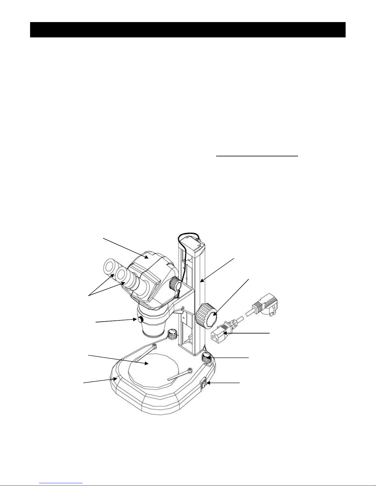
COMPONENTS DIAGRAM
Binocular Head
Stand
Focusing Knob
Eyepieces
Lock-screw
Stage Plate
Base
NOTE: Stand ordered may not be as pictured above.
250 Gibbs Road, Islandia, NY 11749 • 631-582-8440 • www.flexbar.com 4
Power Cord
Shift Knob
Switch
Page 5
6.3:1 ZOOM MICROSCOPE
A
SSEMBLY
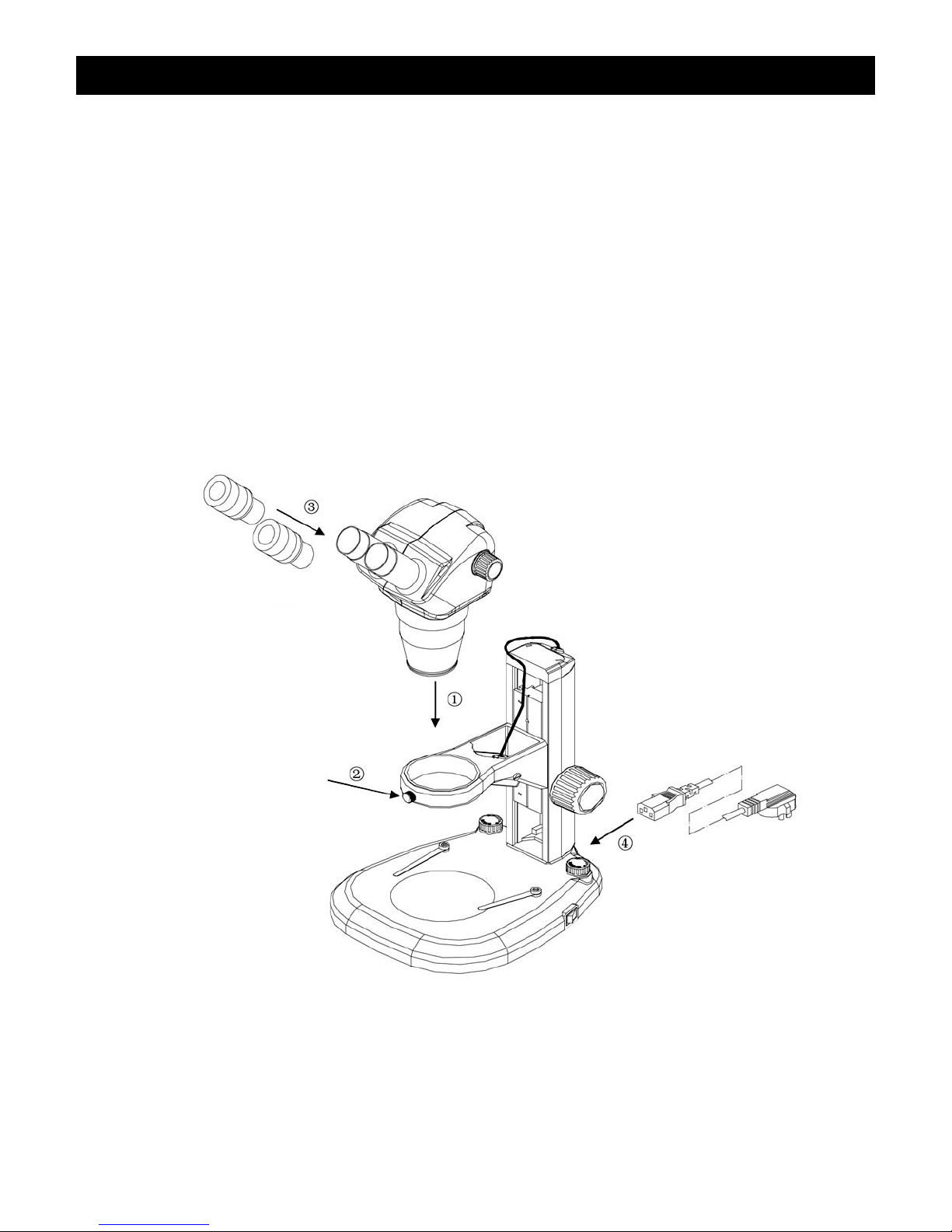
The diagram below shows how to assemble the various modules. The numbers indicate the order of
assembly.
When assembling the microscope, make sure that all parts are free of dust and dirt, and avoid scratching
any parts or touching glass surfaces.
Eyepieces
Binocular Head
Lock-screw
Power Cord
250 Gibbs Road, Islandia, NY 11749 • 631-582-8440 • www.flexbar.com 5
S
tand
Page 6
6.3:1 ZOOM MICROSCOPE
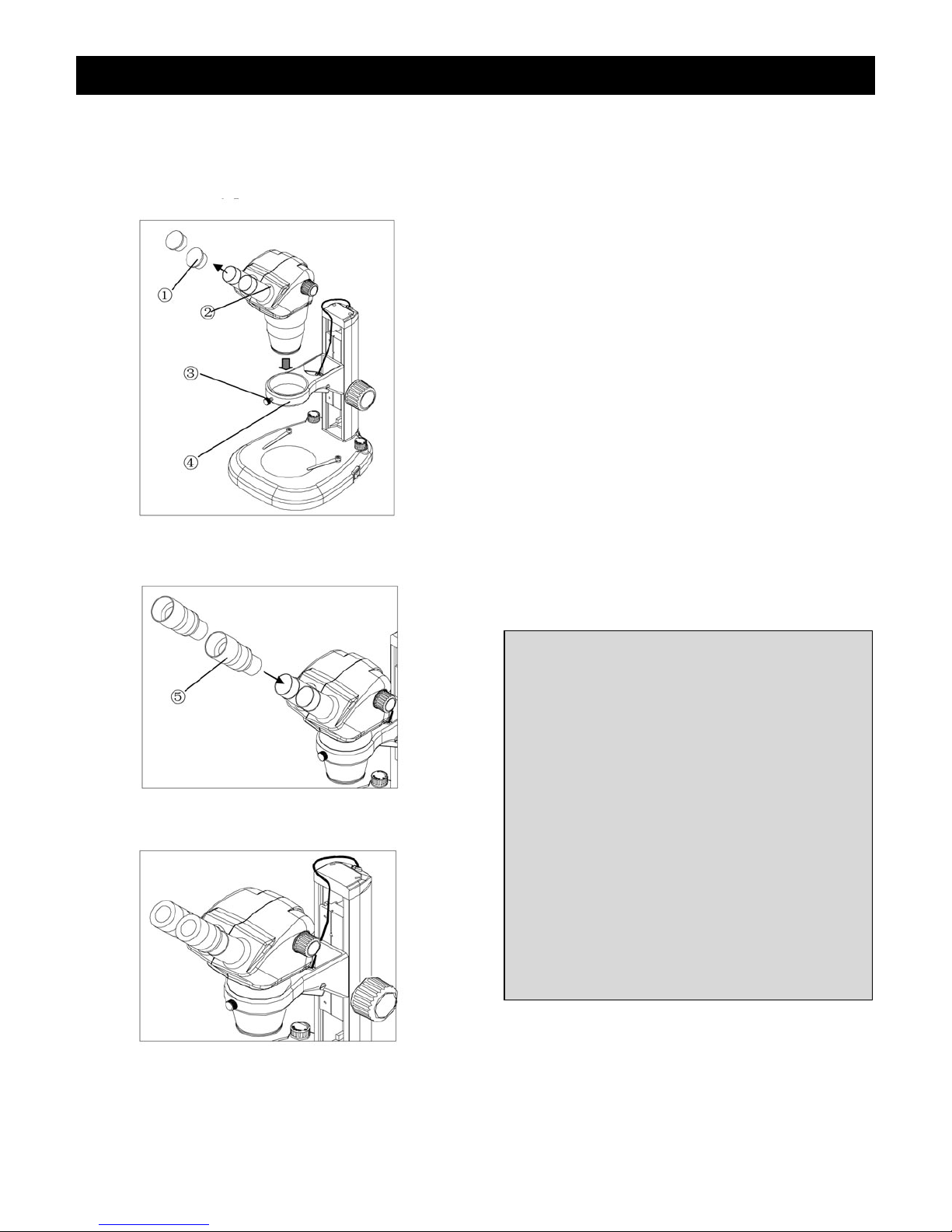
Fig. 1
Fig. 2
Fig. 3
DETAILED ASSEMBLY PROCEDURE
M
ounting the Binocular Head (Fig. 1)
Loosen the clamping knob ③ on the focus
mount ④ and insert the binocular head and
zoom body assembly ② into the bracket of the
focus mount, then tighten the lock screw ③.
Mounting the Eyepieces (Fig. 1, Fig. 2, Fig. 3)
Remove the eyepiece dust caps ① (Fig. 1) and
gently insert the two adjustable eyepieces ⑤
(Fig. 2) into the eyepiece sleeves until they stop,
as shown in Fig.3. Replace the dust caps when
not in use.
IMPORTANT
ENVIRONMENT REQUIREMENTS
1 Ambient temperature: 0°C to 40°C (32°F
to 104°F),Maximum R.H:85%。
2 High temperature will result in moisture
and mildew and could damage instrument.
3 Avoid placing the instrument in a dusty
environment. When not in use, cover the
microscope with the dust cover.
4 Keep the microscope on a flat and stable
surface.
250 Gibbs Road,
Islandia, NY 11749 • 631-582-8440 • www.flexbar.com 6
Page 7
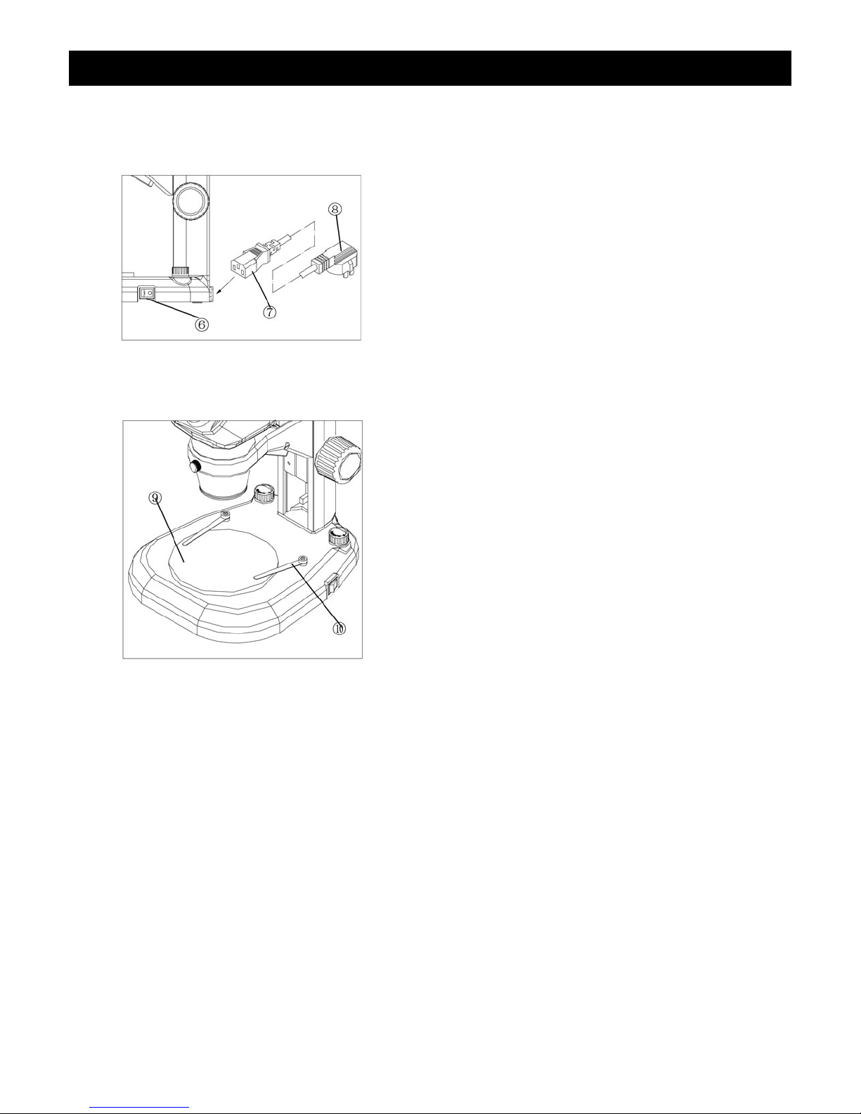
Fig. 4
Fig. 5
Fig. 6
6.3:1 ZOOM MICROSCOPE
F
or Microscopes Purchased
With Illuminated Stands
VOLTAGE CHECK
Confirm that the input voltage indicated on the
rear label of the microscope corresponds to your
line voltage. The use of a different input voltage
than indicated will cause severe damage to your
microscope.
Connecting the Power Cord (Fig. 4)
Turn the power switch ⑥ to the off position (O)
before connecting the power cord ⑦.
Insert the power cord plug ⑦ into the power jack
of the microscope; make sure the connection is
snug.
Plug the power cord ⑧ into the power supply
receptacle.
Using the Glass Stage (Fig. 5)
Set the glass stage plate ⑨ on the center of the
base, and secure the slide with the two clips ⑩.
250 Gibbs Road, Islandia, NY 11749 • 631-582-8440 • www.flexbar.com 7
Page 8
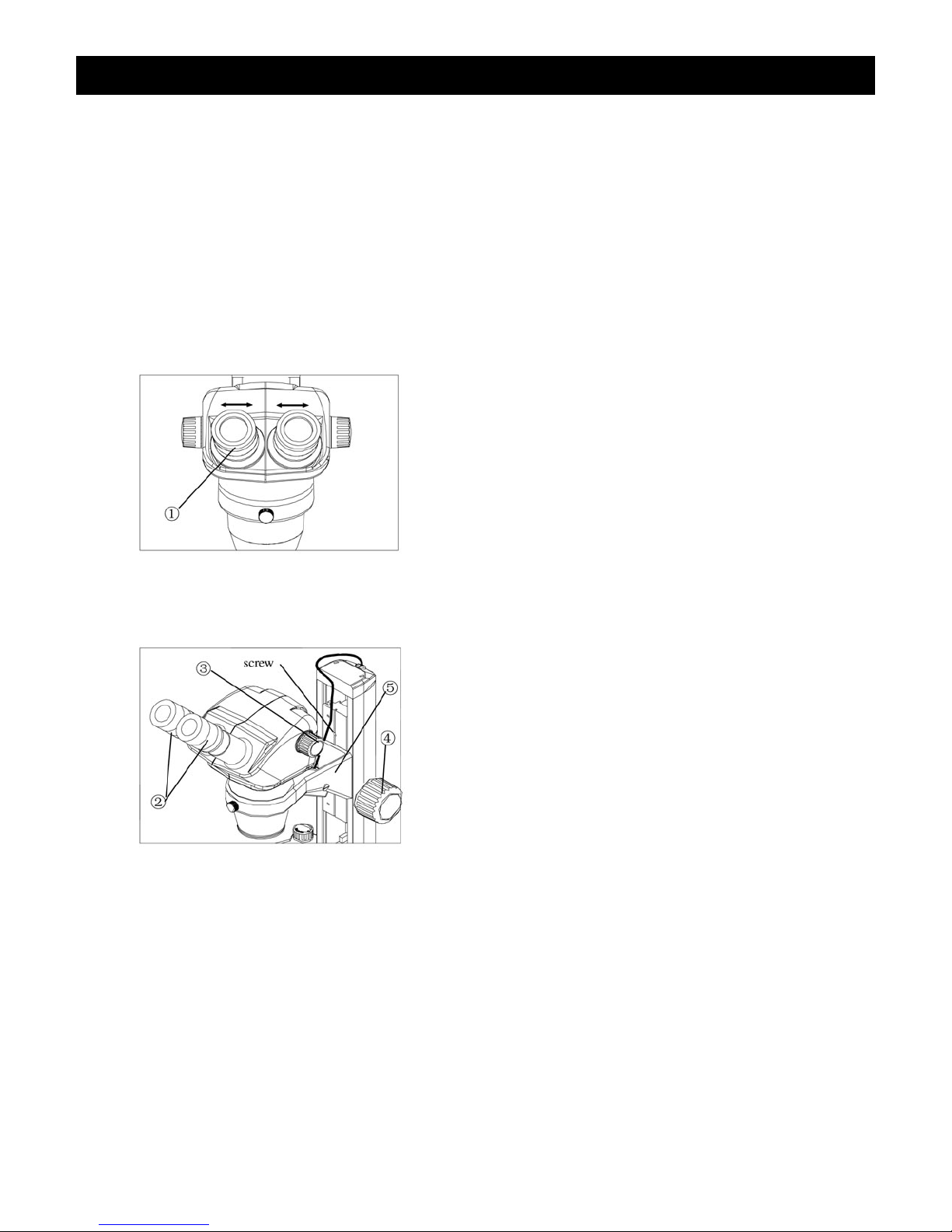
Fig. 6
Fig. 7
6.3:1 ZOOM MICROSCOPE
ADJUSTMENT
A
ND OPERATION
Adjusting Binocular Viewing Head
Adjusting Interpupillary Distance (Fig. 6)
Different users have different interpupillary
distances (this distance is between the centers
of the pupils of each eye). When the operator
changes, it will be necessary to adjust the
interpupillary distance.
hile looking through the eyepieces, hold the
W
left and right eyetubes of the viewing head and
adjust the eyetubes by opening or closing them
until the left and right fields of view coincide
completely and you are able to see a complete
circle.
Adjusting Diopter Ring (Fig. 7)
Set the dioptor rings ②
position. (Do this when users change, because
different users will have different diopter
settings.)
of both eyepieces to “0”
250 Gibbs Road,
Place an easy-to-observe specimen on the
stage plate, i.e., a coin.
Rotate the zoom knob ③
magnification 5x, then turn the focusing knob ④
to focus the specimen.
Rotate the zoom knob ③
magnification 0.8x, looking only into the left
eyepiece, adjust the diopter ring on left eyepiece
to focus the specimen. Then repeat procedure
Islandia, NY 11749 • 631-582-8440 • www.flexbar.com 8
for the right eyepiece.
NOTE:
between the microscope objective to the top of
the specimen) of the microscope is 115mm, the
binocular head bracket ⑤
higher or lower positions according to your
needs by removing the clamping bolt with the
Allen wrench provided.
The working distance (the distance
to the highest
to the lowest
can be mounted onto
Page 9
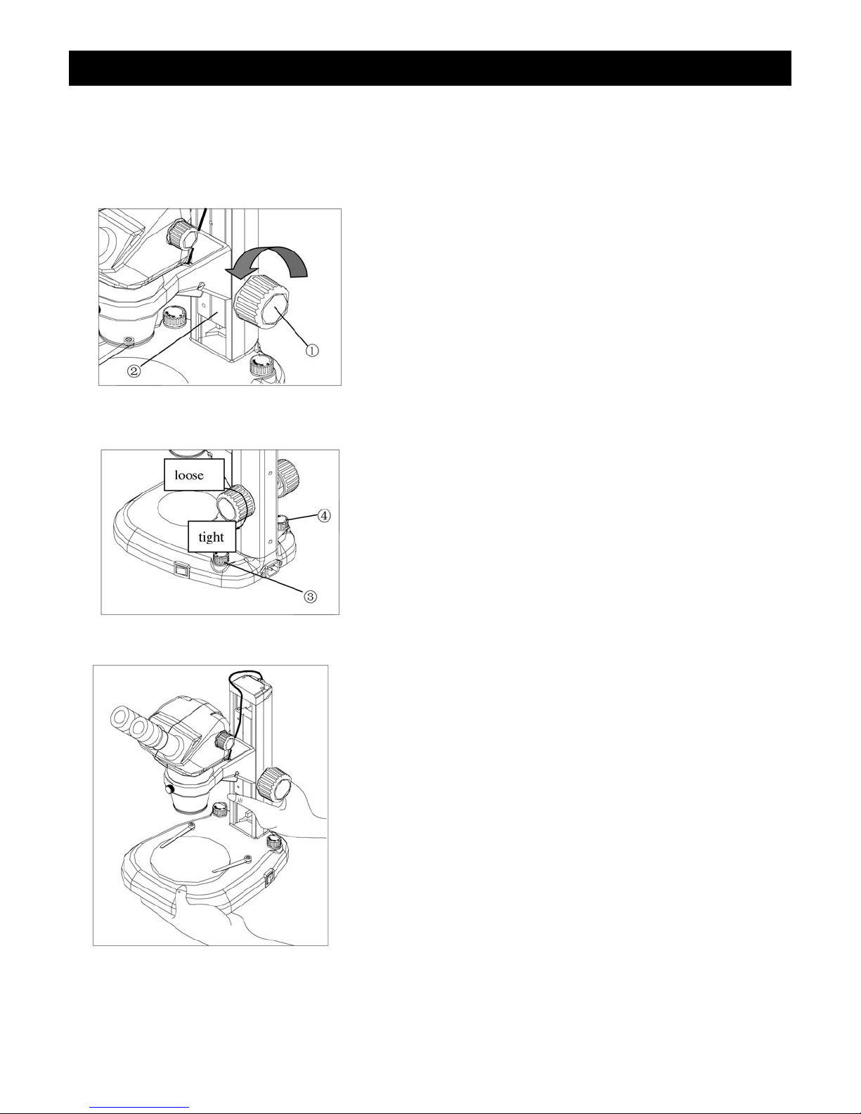
Fig. 8
Fig. 9
Fig. 10
Focus Adjustment
6.3:1 ZOOM MICROSCOPE
A
djusting the Rotation Tension of the
Focus Adjustment Knob (Fig. 8, Fig. 9)
To adjust tension, hold both left and right focus
ad
justment knobs ① with both hands, hold the
left knob (to prevent it from turning), and rotate
the right knob clockwise to increase (tighten) or
counterclockwise to decrease (loosen) the focus
knob tension.
After tension adjustment has been completed,
always rotate both adjustment knobs in the
same direction.
Changing the Magnification
The zooming knobs located on both sides of the
zooming body will change the magnification of
the specimen image.
Total Magnification = Magnification of zoom
body x magnification of eyepiece
(i.e., 0.8 x 10=8x)
NOTE: If using any of the optional auxiliary
objectives, then the above magnification would
be multiplied by auxiliary objective magnification.
(i.e., auxiliary 0.5 x 8=4x)
Moving the Microscope (Fig. 10)
Before moving the microscope, be sure to
remove any slide/samples. When moving the
microscope, hold the stand and base as shown
in Fig. 10 to keep it level.
250 Gibbs Road, Islandia, NY 11749 • 631-582-8440 • www.flexbar.com 9
Page 10

SPECIFICATIONS
Z
oom ratio: 6/1 to 1
Objective magnification: 0.8x~5.0x
Eyepiece: Φ 22 10x Wide Field, interpulpillary adjustable
6.3:1 ZOOM MICROSCOPE
Binocular viewing head: Inclined at 45 degrees, interp
upillary distance range: 52~75mm
Working distance: 115mm
Range of movement: 105mm
Illumination system: LED lamp illumination
Input: 100-240V~, 0.15A, 50.60HZ
Eyepiece
Auxiliary
Objective
115 8-50X 27.5-4.4 12-75X 20.0-3.2 16-100X 15.6-2.5
0.5X 211 4-25X 55.0-8.8 6-37.5X 40.0-6.4 8-50X 31.2-5.0
2X 43.5 16-100X 13.8-2.2 24-150X 10.0-1.6 32-200X 7.8-1.3
Working
Distance
(mm)
Total
agnification
M
WF10X/22 W
Visual Field
(mm)
Total
Magnification
F15X/16 WF20X/12.5
Visual Field
(mm)
Total
Magnification
Visual Field
(mm)
250 Gibbs Road, Islandia, NY 11749 • 631-582-8440 • www.flexbar.com 10
Page 11

6.3:1 ZOOM MICROSCOPE
T
ROUBLESHOOTING
Under certain conditions, performance of this unit may be adversely affected by factors other than
defects. If a problem occurs, please review the following list and take remedial action as needed. If you
cannot solve the problem after checking the entire list, please contact your local dealer for assistance.
Trouble Cause Remedy
Double images I
nterpupillary distance is not correct Readjust it
Diopter adjustment is not correct Readjust it
Dirt appears in the view field Dirt on the specimen C
lean specimen
Dirt on the surfaces of eyepieces Clean eyepieces
Image is not clear D
Image is not clear while focusing
hange
c
irt on the surface of objectives Clear objectives
Diopter adjustment is not correct Readjust diopter
Focusing is not correct R
eadjust it
The focusing knob is not smooth The focusing knob is too tight Loosen it to a suitable position
The image is obscure because of the
ead slipping down during
h
The focusing knob is to o loosen Tighten it to a suitable position
observation
250 Gibbs Road, Islandia, NY 11749 • 631-582-8440 • www.flexbar.com 11
Page 12

6.3:1 ZOOM MICROSCOPE
MAINTENANCE
lease remember to never leave the microscope with eyepieces removed and always protect the
P
microscope with the dust cover when not in use.
SERVICE
Flexbar microscopes are precision instruments which require periodic servicing to keep them
performing properly and to compensate for normal wear. A regular schedule of preventative maintenance
by qualified personnel is highly recommended. Your authorized Flexbar distributor can arrange for
this service. Should unexpected problems be experienced with your instrument, proceed as follows:
1. Contact the Flexbar distributor from whom you purchased the microscope. Some
problems can be resolved simply over the telephone.
2. If it is determined that the microscope should be returned to your Flexbar distributor or to
Flexbar for warranty repair, pack the instrument in its original Styrofoam shipping carton. If you no
longer have this carton, pack the microscope in a crush-resistant carton with a minimum of three inches
of a shock absorbing material surrounding it to prevent in-transit damage. The microscope should be
wrapped in a plastic bag to prevent Styrofoam dust from damaging the microscope. Always ship the
microscope in an upright position; NEVER SHIP A MICROSCOPE ON ITS SIDE. The microscope or
component should be shipped prepaid and insured.
LIMITED SCOPE WARRANTY
This microscope is warranted to be free from defects in material and workmanship for a period of five (5) years for
mechanical and optical components and one (1) year for electrical components from the date of invoice to the
original (end user) purchaser. This warranty does not cover damage caused in-transit, misuse, neglect, abuse or
damage resulting from improper servicing or modification by other then Flexbar approved service personnel.
This warranty does not cover any routine maintenance work or any other work, which is reasonably expected to be
performed by the purchaser. Normal wear is excluded from this warranty. No responsibility is assumed for
unsatisfactory operating performance due to environmental conditions such as humidity, dust, corrosive chemicals,
deposition of oil or other foreign matter, spillage or other conditions beyond the control of Flexbar. This
warranty expressly excludes any liability by Flexbar. for consequential loss or damage on any grounds, such as
(but not limited to) the non-availability to the End User of the product(s) under warranty or the need to repair work
processes. Should any defect in material, workmanship or electronic component occur under this warranty contact
your Flexbar distributor or Flexbar at (631) 582-8440. This warranty is limited to the continental United
States of America. All items returned for warranty repair must be sent freight prepaid and insured to Flexbar,
250 Gibbs Road, Islandia, NY 11749 – USA. All warranty repairs will be returned freight prepaid to any destination
within the continental United States of America. For all foreign warranty repairs, return freight charges are the
responsibility of the individual/company who returned the merchandise for repair.
250 Gibbs Road, Islandia, NY 11749 631-582-8440 631-582-8487 www.flexbar.com
12
 Loading...