

Page 1

ULTRASONIC THICKNESS GAGE
MODEL NO. 15947 & 15949
OPERATION MANUAL
250 Gibbs Road • Islandia, NY 11749
Tel: (631) 582-8440 • Fax: (631) 582-8487
E-Mail: [email protected]
www.flexbar.com
Page 2

INDEX
1) GENERAL
1.1) APPLICATIONS 3
1.2) BASIC WORKING PRINCIPLE 3
2) SPECIFICATIONS 3
3) DIAGRAM
4) MAIN FUNCTIONS 5
4.1) PREPARING FOR MEASUREMENT 5
5) SETTING PARAMETERS 5
5.1) Velocity 6
a) Velocity Setting 6
b) Velocity Measuring
5.2) Probe selection 6
5.3) Resolution 7
6) TESTING PROCEDURE 7
7) CALIBRATION 7
8) MEASURING THICKNESS 7
9) MAINTENANCE 8
9.1) Battery replacement 8
9.2) Storage 8
Appendix A: Decimal and Fractions to Millimeters 9
Appendix B: Millimeters to Inches 10
Appendix C: Sound Velocity in Materials 11
Model#15947 & 15949 4
6
2
Page 3

1. GENERAL
1.1) APPLICATIONS
The Flexbar Ultrasonic Thickness Gage, Model No. 15947 & 15949 are
designed for measuring the thickness of metals, plastics, ceramics, glass and other
ultrasonic wave conducting materials with two parallel surfaces (top & bottom).
The 15947/15949 can be used in industrial applications to perform precise
measurements on various kinds of materials, parts and components. Additionally, it can
be used to monitor various kinds of pipes and pressure vessels for decreasing thickness
due to corrosion and/or erosion.
1.2) BASIC WORKING PRINCIPLE
The basic principle of the ultrasonic wave in a thickness measurement is similar to that
of an optical wave. The ultrasonic wave pulses are transmitted by the probe face and
are coupled to the object to be measured using a viscous fluid called “couplant”. These
ultrasonic pulses propagate through the measured object and reflect back to the
transducer when they encounter the back surface. The thickness of the object is
determined by precisely measuring the time the ultrasonic wave travels in the object.
2) SPECIFICATIONS
DISPLAY:
RESOLUTION:
WORKING FREQUENCY:
MEASURING RANGE:
LOWER MEASURING LIMIT FOR PIPES:
MEASURING ERROR:
ADJUSTING RANGE OF SOUND VELOCITY
MEASUREMENT OF SOUND VELOCITY WITH
KNOWN THICKNESS VALUE:
MEASUREMENT RANGE:
IF THICKNESS IS LESS THAN 0.8” (20mm):
IF THICKNESS IS GREATER THAN 0.8” (20mm)
RANGE OF OPERATING TEMPERATURE:
POWER SUPPLY:
POWER CONSUMPTION:
Auto Power Off
DIMENSIONS:
WEIGHT:
FOUR DIGIT LCD DISPLAY
0.01in / 0.1mm & 0.001” / 0.01MM
5 MHz
.047in – 8.0in (1.2 - 200.0 MM) (STEEL)
0.8 X 0.1” or 20 X 3mm (STEEL)
+/- (1%H+0.004”) or ±(1%H+0.1)MM
0.039 to 0.3937in/us or (1000-9999 M/S)
37-373 MILES/MIN (1000-9999 M/S)
+/- 0.004”H x 100% or ± 1mm/H X 100%
± 5%
32-104 DEGREES F (0-40 DEGREES C)
TWO AAA BATTERIES
3 Volts at less than 20MA
2 Minutes
4.3 X 2.4 X 0.9IN
4.7oz
H = actual thickness of the object to be
measured
3
Page 4
7
1
3
5
UTG-
6
2
4
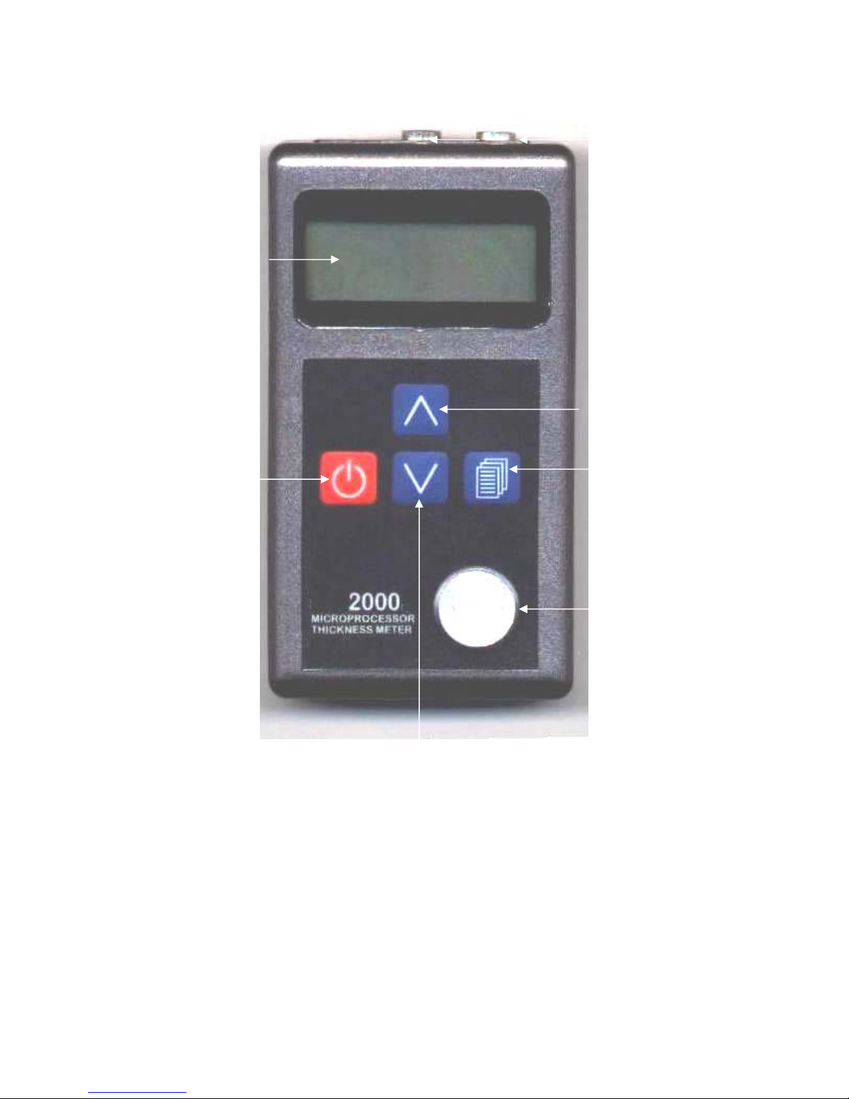
Model 15947/15949
1. LCD Screen 2. Calibration Block
3. Increase/Change Setting/Backlight 4. Decrease/Change Setting/AutoCalibrat
5. Power On/Off 6. Menu Program/Save
7. Probe Ports
4
Page 5
1
7
3
9
5
UTG-
8
6
2
4
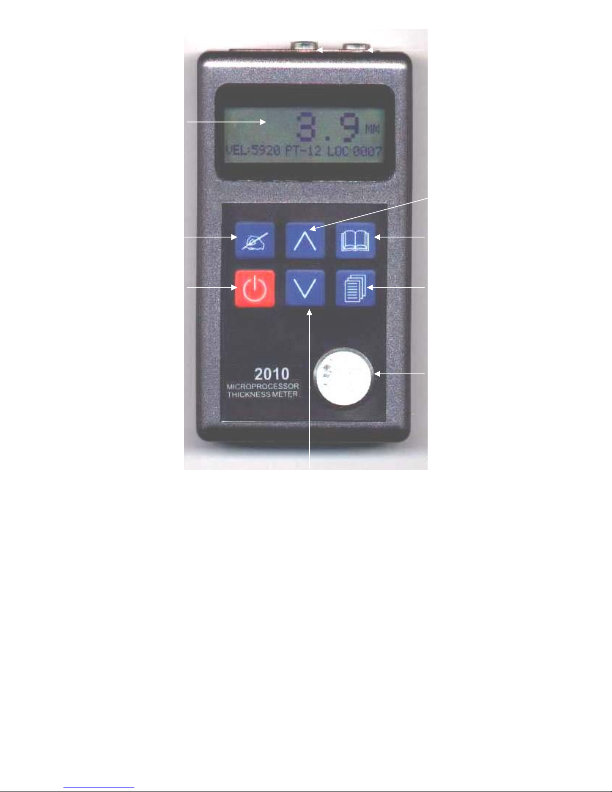
Model 15947/15949
1. LCD Screen 2. Test Shim
3. Increase/Change Setting/Backlight 4. Decrease/Change Setting/Auto
Calibration
5. Power On/Off 6. Menu Program/Save
7. Probe Ports 8. Memory Recall (15947/15949 Only)
9. Store Data (15947/15949 Only)
5
Page 6
5
10
1
7
3
8
6
2
4
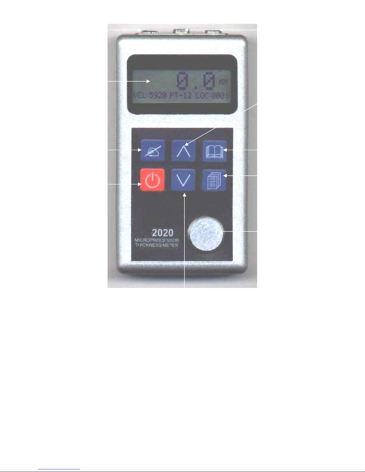
MODEL 15947/15949
1. LCD Screen 2. Calibration Pad
3. Increase/Change Setting/Backlight 4. Decrease/Change Setting/Auto
Calibration
5. Power On/Off 6. Menu Program/Save
7. Probe Port 8. Memory Recall
(15947/15949 Only)
9. Store Data 10. RS-232/Printer Port
6
Page 7
4) MAIN FUNCTIONS
• Automatic error correction capabilities
• Automatic linear compensation to improve accuracy (involves the correction of
non-linear errors resulting from the probe).
• Up and down keys allow for quick adjustment of sound velocity and thickness,
as well as fast checking of memory unit.
• Automatic coupling icon indicates the coupling state: stable/unstable.
• Direct determination of the sound velocity according to the thickness of the
master testing block.
• Low battery indicator
4.1) PREPARING FOR MEASUREMENT
Automatic instrument shut down during idle use period
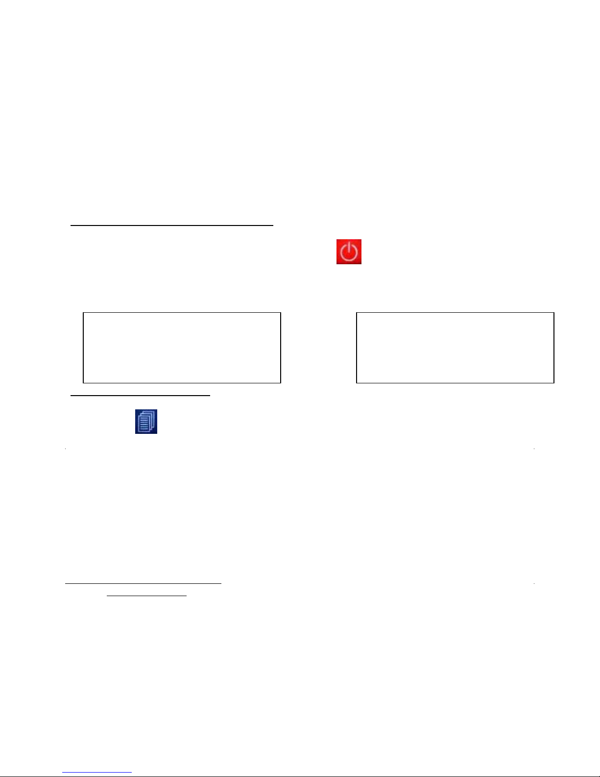
Place the probe into the probe socket of the unit , push
seconds, the screen will display 0.00in, 0.000in, 0.0mm, or 0.00mm (depending on previous
setting), the sound velocity used during the last testing procedure along with the probe type
and location. (See Below)
5) SETTING PARAMETERS
A) Press the
Model# 15947 Model# 15949
1. Measurement 1. Measurement
2. Velocity 2. Velocity
3. Probe Setting 3. Probe Setting
4. Resolution 4. Resolution
5. Location 5. Location
6. Limitation 6. Default
7. Average
8. Print
9. Default
Note: 1. Measurement = Main test screen
0.000IN
VEL:0.230 PT-12
button. The screen will display as follows:
to turn the unit on. After a few
0.00mm
VEL:5920m/s PT-12
7
Page 8
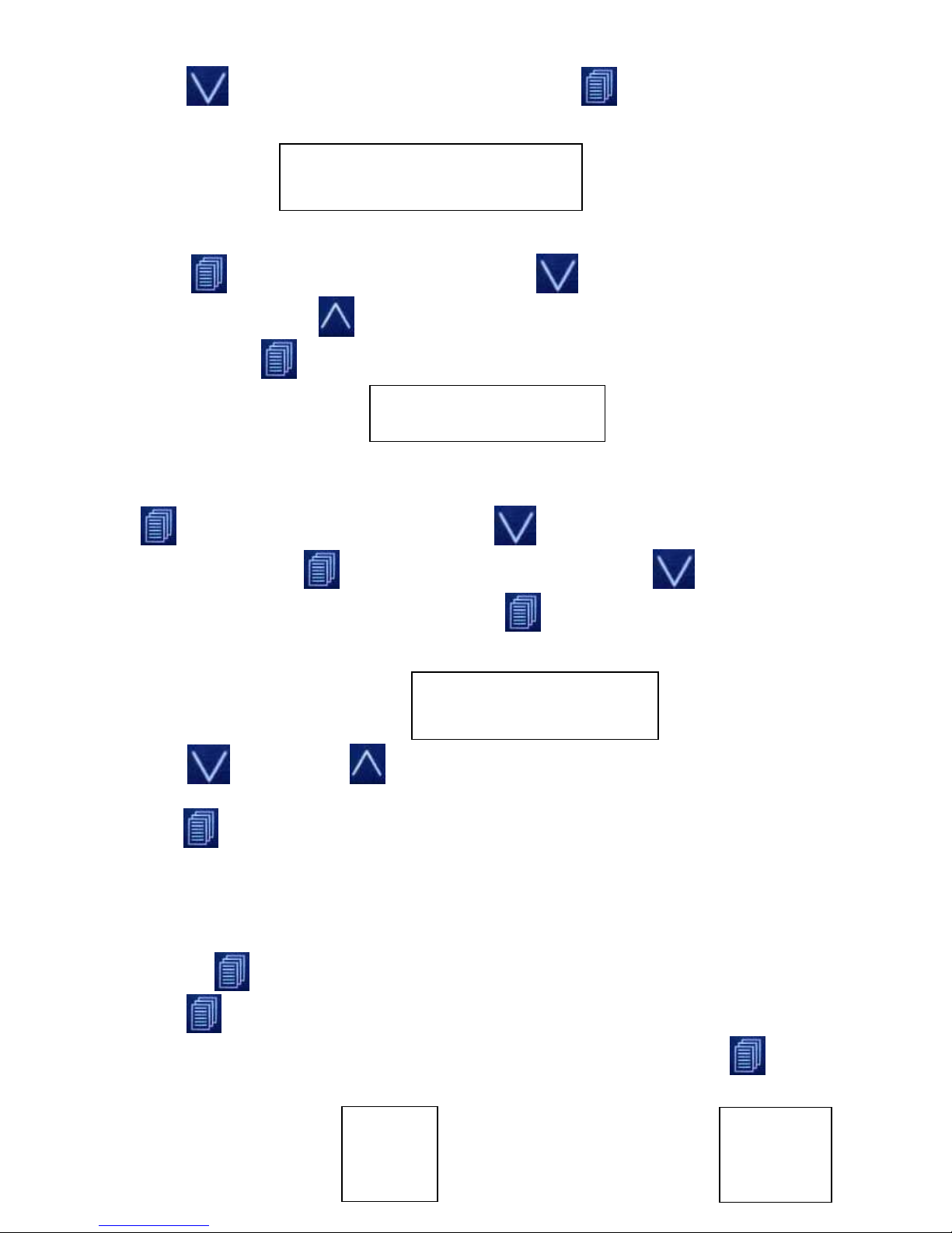
5.1) Velocity
Press the
velocity parameter. The screen will display as follows:
a) Vel. Setting
Press the
column to column. Use the
been set, press the
b) Vel.Measuring
In the normal measurement mode, take a thickness reading on the sample to be tested. Press
the
button to enter the menu mode. Press the button to move the cursor to the 2.
button once to select 2. Velocity. Press the button to enter into the
1. Vel. Setting
2. Vel. Measuring
button to enter VEL SETTING. Use the button to move the cursor from
button to change the number value. When the parameter has
button to save entry.
INPUT VELOCITY
5920 m/s
Velocity menu. Press the button to enter this mode. Then press the button to move
the cursor to 2. Velocity Measuring. Next press the button to enter this mode. The screen
looks similar to this.
INPUT THICKNESS
2.016in 0.2340
Press the
the thickness number agrees with the actual thickness of the sample being measured.
button and the button to change the sound velocity parameter such that
Press the button to accept this velocity and exit the Velocity menu.
To measure the sound velocity of a specific material, use a testing block with a known thickness value. Similar to the measurement
of the materials thickness, use a vernier caliper or micrometer to obtain an accurate measurement of the testing block. Then couple
the probe to the testing block until a thickness value is displayed. Remove the probe and use the keypad to adjust the displayed
value to match the actual thickness of the testing block.
5.2 PROBE SELECTION
A) Press the
Press the
button and scroll down to: 3. PROB SETTING.
button to enter parameter.
Using the arrow keys, select your probe type and highlight the number. Press the
select and store in memory. (This gage is supplied with a PT-12 probe)
Visible on first screen:
nd
Visible on 2
screen:
1. PT-12
1.0-200
2. PT-06
0.8-50
button to
3. ZT-12
2.0-250
4. GT-13
3.0-100
8
Page 9
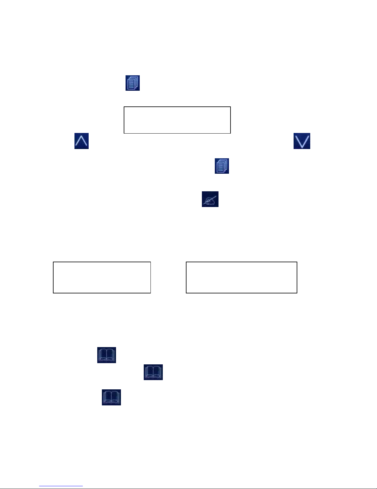
5.4 LOCATION (Memory Groups)
• Model# 15949 has a memory capacity of 2000 measurements. These can be stored in
any group from 0000 to 1999.
• Model# 15947 has a memory capacity of 4000 measurements. These can be stored in
any group from 0000 to 3999.
To choose a specific memory location, you must go to the main menu and scrol down to
*Models 15947 & 15949 only
#5 LOCATION. Press the
input location and show the four digits for entering and recording your desired memory location.
Using the
button, change the column. Continue to change numerals and columns in this manner. When
the desired memory location has been chosen, press the
button, choose your desired numeral for the first column. Using the
button to enter location parameter. The screen will display
INPUT LOCATION
0001
button to save this entry.
Method of saving your measurement:
1) Take a measurement of the sample piece to be tested. As soon as the measurement is
displayed on the LCD screen, you must push the
your chosen memory location. For each time you save a measurement, the gauge will
automatically store the chosen value in the next consecutive memory location.
For instance, if you chose your first memory location to be 0560. That number will be your first
saved value. The next saved measurement value will be stored in location number 0561 and so
on. You can always change your location group at any time by following the instructions in the
previous paragraph.
VEL:5920 PT-12 LOC: 0002
3.02mm
VEL:5920 PT-12 LOC: 0003
button to save the measurement in
3.02mm
Test#1 Test#2
5.5 MEMORY RECALL
if you need to start retrieving measurements starting from 0001, you should be in the main test
screen. Press the
location 0001. You can press the
values in ascending order.
Example: push the
again and the display will show the saved value from location 0002, etc.
button and the gauge will display the measurement saved in memory
button and the display will show location 0001. Push the same button
button as many times as you need to display the saved
9
Page 10
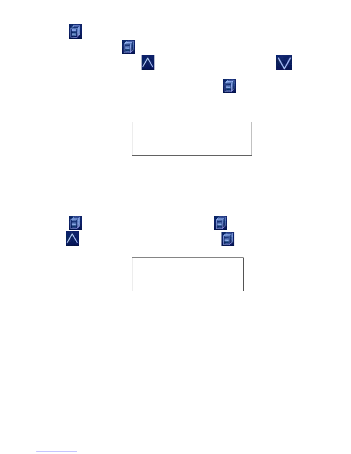
5.6 LIMITATION (Model# 15947 only)
Press the
6. LIMITATION. Press the
Set your lower limit by pressing the
button to change your column. Proceed to enter upper limit using the same method. When the
data has been entered to your requirements, you must press the
While taking measurements, if your value is lower than the set limit, the letter “ L” will be
displayed in the top right corner of the LCD screen. If the value is greater than the set limit, the
letter “H” will appear in the top right corner of the screen.
5.7 AVERAGE (Model# 15947 only)
The mean value can be achieved by programming from 2 to 9 times.
button and return to the main menu. Scroll down until you see the
button to enter the limitation parameter.
button to advance the numerals. Press the
button to save the entry.
LO. LIM. 00.00mm
UP. LIM. 99.00mm
Example: If you need to show an average after 3 tests, you would enter 3 as your average
number. You then perform 3 tests(SEE DIRECTIONS BELOW) and the gauge will then display
the average of those 3 tests. If you need an average displayed after 9 tests(maximum), you
should enter 9 as your average number.
Press the button and proceed to 7.AVERAGE. Press the button to enter parameter.
Using th
button, change the number form 2 to 9. Press the button to save entry.
AVERAGE TIMES
3
a) Directions for testing for averages:
Place the probe on your test sample. Get your measurement value.
1)
2) Remove the probe from the test sample. Wait for 3 seconds. The gauge will “beep” and the
average number shown on the LCD screen will descend from 3 to 2.
3) Perform this procedure again. Wait for the beep and the gauge will change the average
number from 2 to 1.
4) Perform the 3
and automatically show the average of the 3 tests you just performed.
rd
and final test. Remove the probe from the test sample. The gauge will beep
Note: a new average time must be entered before each set to be performed.
10
Page 11
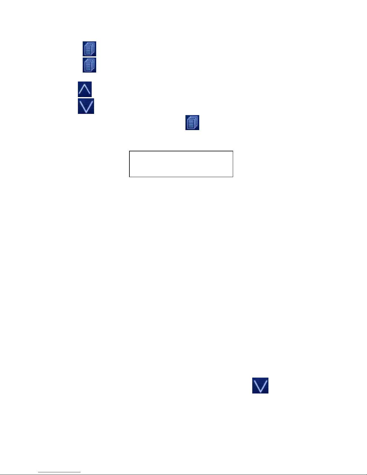
5.8 PRINTING (Model# 15947 only)
If you want to print the stored values, you must first determine the initial location number and
the last location number to be printed.
• Press the
• Press the
• The display will show a start location and an end location.
• Use the
• Use the
• When the data entry has been set, press the
• The gauge will automatically begin displaying and printing all values stored in the entered
location numbers.
a) Printing to your PC
• Follow the instructions noted above. Instaed of printing to your mini-printer, the values will
be displayed on your PC screen.
button to enter main menu. Scroll down to the 8.PRINT.
button to enter parameter.
button to change the numerals
button to change the columns.
button to save this entry.
START LOC. 0000
END LOC. 0000
(Model# 15947 only)
Note: Use supplied cables to connect the gauge to the PC.
6) TESTING PROCEDURE
• Assuming all parameters have been entered, place a small drop of coupling gel
(supplied) to the surface of the sample to be tested.
NOTE
touching the probe.
• Place the probe directly on the gel spot holding steady and firm. Do not move the probe
:
Do not apply Gel to the probe as that may result in attempted measurements with no sample
until the measured value has been displayed. At this time, you can remove the probe from
the test sample.
Note: Coupling gel must be used to perform all ultrasonic tests.
7) CALIBRATION
Each time the probe or battery is changed, a calibration should be performed in order to
guarantee measuring accuracy. If necessary, repeat the calibration several times. Adjust the
sound velocity to 2330in/us (5981m/s) (steel/iron).
• Apply the coupling gel to the testing block(see fig. 1, #6) (metallic disc on face of
gage), which is built into the unit, and couple the probe to the testing block. At this time,
the screen displays .157in(4mm),. This indicates that the calibration is over. If the screen
displays something other than .157in (4mm), you should press the
gauge will automatically calibrate itself to .157in(4mm).
At that time, you can begin to perform your testing.
button and the
11
Page 12
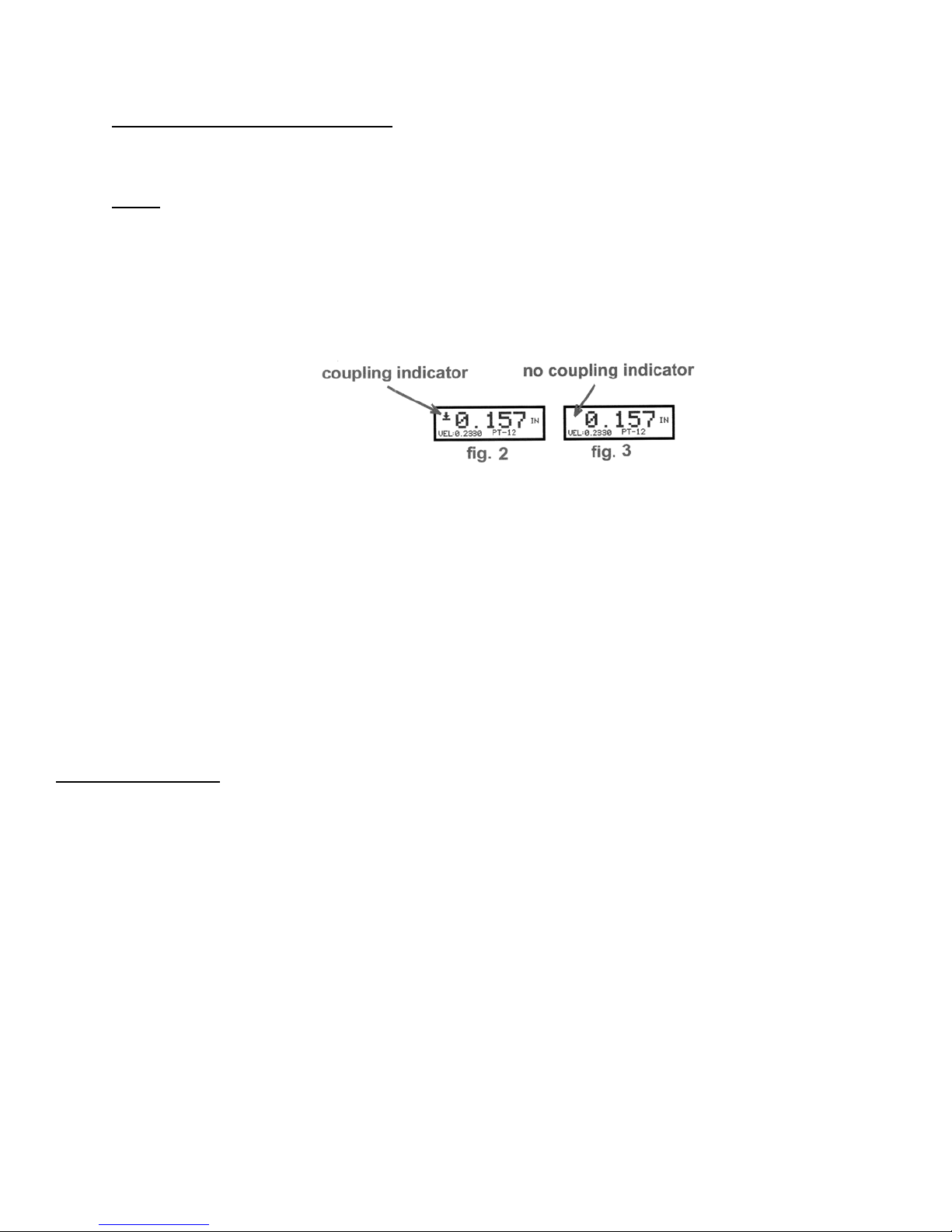
8) MEASURING THE THICKNESS
Apply the coupling gel to the material to be measured and then couple the probe to the
material. This will begin the measurement, and the screen will then display the thickness of the
material (see fig.2).
NOTE: when the probe is coupled to the material, a coupling indicator will be displayed on the LCD
screen. If the coupling indicator flickers or does not appear, the coupling process is erroneous or
incomplete.
Once a thickness measurement has been obtained, remove the probe. The thickness value will remain on
the LCD screen, however, the coupling indicator will disappear (see fig.3)
NOTE
touching the probe.
:
Do not apply Gel to the probe as that may result in attempted measurements with no sample
* AUTOMATIC SHUT-OFF
If the 15947/15949 remains idle for 2 minutes, the unit will automatically shut off.
* PRECAUTIONS
The surface of the probe is made of Polypropylene resin and is very sensitive to heavy scratches and rough
surfaces. Therefore, it is recommended to apply only a light to moderate amount of pressure on the probe during
testing.
The temperature of the surface of the object to be measured should not exceed 140°F (60°C).
Keep the 15947/15949 clean and avoid exposure to dust, iron chips, carbon particles.
10) MAINTENANCE
10.1) REPLACING THE BATTERIES
Once the low battery indicator appears on the screen, the batteries should be replaced.
Use the following procedure when replacing the batteries.
• Power unit off or wait until the unit turns off automatically.
• Open the battery compartment by pressing your thumb down on the cover and sliding it outwards.
• Remove the used batteries and insert new batteries into the compartment, paying close attention to the
polarity of the battery.
10.2) STORING THE GAGE
Be sure to clean the probe and cable after each use. Grease, oil and dust will cause the cable of the probe to age
and crack.
If the unit is not to be used for a long period of time, remove the batteries to avoid battery leakage and corrosion
of the battery contacts.
Avoid storing the unit in a damp or extremely hot environment.
12
Page 13
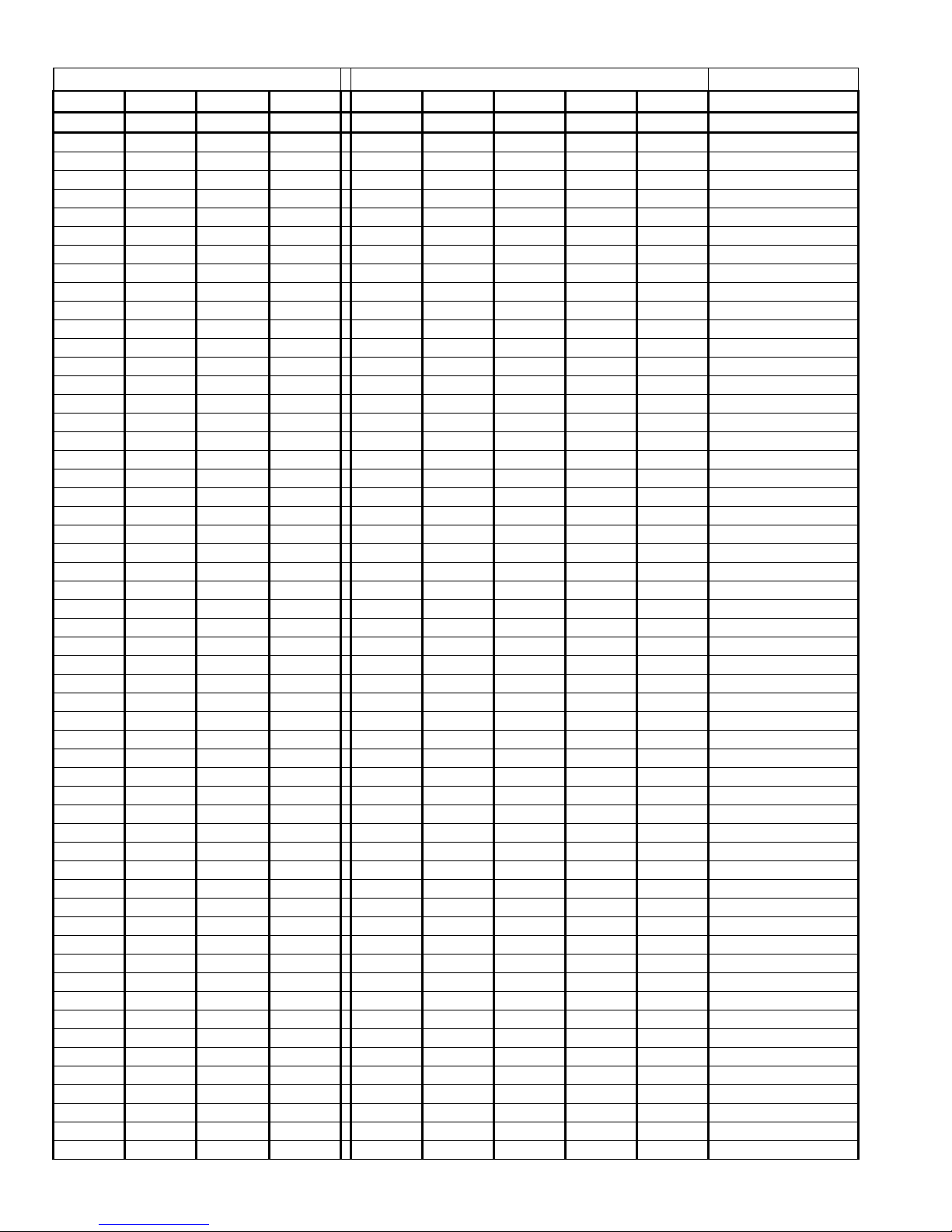
Inch to Millimeter Conversion Table
Decimals to Millimeters Fractions to Decimals to Millimeters
Decimal mm Decimal mm Fraction Decimal mm Fraction Decimal mm
0.001 0.0254 0.500 12.7000 1/64 0.0156 0.3969 33/64 0.5156 13.0969
0.002 0.0508 0.510 12.9540 1/32 0.0312 0.7938 17/32 0.5312 13.4938
0.003 0.0762 0.520 13.2080 3/64 0.0469 1.1906 35/64 0.5469 13.8906
0.004 0.1016 0.530 13.4620
0.005 0.1270 0.540 13.7160
0.006 0.1524 0.550 13.9700 1/16 0.0625 1.5875 9/16 0.5625 14.2875
0.007 0.1778 0.560 14.2240
0.008 0.2032 0.570 14.4780 5/64 0.0781 1.9844 37/64 0.5781 14.6844
0.009 0.2286 0.580 14.7320 3/32 0.0938 2.3812 19/32 0.5938 15.0812
0.580 14.7320 7/64 0.1094 2.7781 39/64 0.6094 15.4781
0.010 0.2540 0.590 14.9860
0.020 0.5080
0.030 0.7620
0.040 1.0160 0.600 15.2400
0.050 1.2700 0.610 15.4940 1/8 0.1250 3.1750 5/8 0.6250 15.8750
0.060 1.5240 0.620 15.7480
0.070 1.7780 0.630 16.0020
0.080 2.0320 0.640 16.2560 9/64 0.1406 3.5719 41/64 0.6406 16.2719
0.090 2.2860 0.650 16.5100 5/32 0.1562 3.9688 21/32 0.6562 16.6688
0.660 16.7640 11/64 0.1719 4.3656 43/64 0.6719 17.0656
0.100 2.5400 0.670 17.0180
0.110 2.7940 0.680 17.2720
0.120 3.0480 0.690 17.5260 3/16 0.1875 4.7625 11/16 0.6875 17.4625
0.130 3.3020
0.140 3.5560
0.150 3.8100 13/64 0.2031 5.1594 45/64 0.7031 17.8594
0.160 4.0640 0.700 17.7800 7/32 0.2188 5.5562 23 8/25 0.7188 18.2562
0.170 4.3180 0.710 18.0340 15/64 0.2344 5.9531 47/64 0.7344 18.6531
0.180 4.5720 0.720 18.2880
0.190 4.8260 0.730 18.5420 1/4 0.2500 6.3500 3/4 0.7500 19.0500
0.740 18.7960
0.200 5.0800 0.750 19.0500
2.210 5.3340 0.760 19.3040 17/64 0.2656 6.7469 49/64 0.7656 19.4469
0.220 5.5880 0.770 19.5580 9/32 0.2812 7.1438 25/32 0.7812 19.8438
0.230 5.8420 0.780 19.8120 19/64 0.2969 7.5406 51/64 0.7969 20.2406
0.240 6.0690 0.790 20.0660
0.250 6.3500
0.260 6.6040
0.270 6.8580 0.800 20.3200 5/16 0.3125 7.9375 13/16 0.8125 20.6375
0.280 7.1120 0.810 20.5740 21/64 0.3281 8.3344 53/64 0.8281 21.0344
0.290 7.3660 0.820 20.8280 11/32 0.3438 8.7312 27/32 0.8438 21.4312
0.300 7.6200 0.830 21.0820 23/64 0.3594 9.1281 55/64 0.8594 21.8281
0.310 7.8740 0.840 21.3360
0.320 8.1280 0.850 21.5900 3/8 0.3850 9.5250 7/8 0.8750 22.2250
0.330 8.3820 0.860 21.8440
0.340 8.6360 0.870 22.0980 25/64 0.3906 9.9219 57/64 0.8906 22.6219
0.350 8.8900 0.880 22.3520 13/32 0.4062 10.3188 29/32 0.9062 23.0188
0.360 9.1440 0.890 22.6060 27/64 0.4219 10.7156 59/64 0.9219 23.4156
0.370 9.3980
0.380 9.6520
0.390 9.9060 0.900 22.8600
0.400 10.1600 0.910 23.1140 7/16 0.4375 11.1125 15/16 0.9375 23.8125
0.410 10.4140 0.920 23.3680
0.420 10.6680 0.930 23.6220
0.430 10.9220 0.940 23.8760
0.440 11.1760 0.950 24.1300 29/64 0.4531 11.5094 61/64 0.9531 24.3094
13
Page 14
0.450 11.4300 0.960 24.3840 15/32 0.4688 11.9062 31/32 0.9688 24.6062
0.460 11.6840 0.970 24.6380 31/64 0.4844 12.3031 63/64 0.9844 25.0031
0.470 11.9380 0.980 24.8920
0.480 12.1920 0.990 25.1460
0.490 12.4460 1.000 25.4000 1/2 0.5000 12.7000 1 1.0000 25.4000
Millimeter to Inch Conversion Table
mm Decimal mm Decimal mm Decimal mm Decimal mm Decimal
0.01 0.00039 0.41 0.01614 0.81 0.03189 21 0.82677 61 2.40157
0.02 0.00079 0.42 0.01654 0.82 0.03228 22 0.86614 62 2.44094
0.03 0.00118 0.43 0.01693 0.83 0.03268 23 0.90551 63 2.48031
0.04 0.00157 0.44 0.01732 0.84 0.03307 24 0.94488 64 2.51969
0.05 0.00197 0.45 0.01772 0.85 0.03346 25 0.98425 65
0.06 0.00236 0.46 0.01811 0.86 0.03386 26 1.02362 66 2.59843
0.07 0.00276 0.47 0.01850 0.87 0.03425 27 1.06299 67 2.63780
0.08 0.00315 0.48 0.01890 0.88 0.03465 28 1.10236 68 2.67717
0.09 0.00354 0.49 0.01929 0.89 0.03504 29 1.14173 69 2.71654
0.10 0.00394 0.50 0.01969 0.90 0.03543 30 1.18110 70 2.75591
0.11 0.00433 0.51 0.02008 0.91 0.03583 31 1.22047 71 2.79528
0.12 0.00472 0.52 0.02047 0.92 0.03622 32 1.25984 72 2.83465
0.13 0.00512 0.53 0.02087 0.93 0.03661 33 1.29921 73 2.87402
0.14 0.00551 0.54 0.02126 0.94 0.03701 34 1.33858 74 2.91339
0.15 0.00591 0.55 0.02165 0.95 0.03740 35 1.37795 75 2.95276
0.16 0.00630 0.56 0.02205 0.96 0.03780 36 1.41732 76 2.99213
0.17 0.00669 0.57 0.02244 0.97 0.03819 37 1.45669 77 3.03150
0.18 0.00709 0.58 0.02283 0.98 0.03858 38 1.49606 78 3.07087
0.19 0.00748 0.59 0.02323 0.99 0.03898 39 1.53543 79 3.11024
0.20 0.00787 0.60 0.02362 1.00 0.03937 40 1.57480 80 3.14961
0.21 0.00827 0.61 0.02402 1 0.03937 41 1.61417 81 3.18898
0.22 0.00866 0.62 0.02441 2 0.07874 42 1.65354 82 3.22835
0.23 0.00906 0.63 0.02480 3 0.11811 43 1.69291 83 3.26772
0.24 0.00945 0.64 0.02520 4 0.15748 44 1.73228 84 3.30709
0.25 0.00984 0.65 0.02559 5 0.19685 45 1.77165 85 3.34646
0.26 0.01024 0.66 0.02598 6 0.23622 46 1.81102 86 3.38583
0.27 0.01063 0.67 0.02638 7 0.27559 47 1.85039 87 3.42520
0.28 0.01102 0.68 0.02677 8 0.31496 48 1.88976 88 3.46457
0.29 0.01142 0.69 0.02717 9 0.35433 49 1.92913 89 3.50394
0.30 0.01181 0.70 0.02756 10 0.39370 50 1.96850 90 3.54331
0.31 0.01220 0.71 0.02795 11 0.43307 51 2.00787 91 3.58268
0.32 0.01260 0.72 0.02835 12 0.47244 52 2.04724 92 3.62205
0.33 0.01299 0.73 0.02874 13 0.51181 53 2.08661 93 3.66142
0.34 0.01339 0.74 0.02913 14 0.55118 54 2.12598 94 3.70079
0.35 0.01378 0.75 0.02953 15 0.59055 55 2.16535 95 3.74016
0.36 0.01417 0.76 0.02992 16 0.62992 56 2.20472 96 3.77953
0.37 0.01457 0.77 0.03032 17 0.66929 57 2.24409 97 3.81890
0.38 0.01496 0.78 0.03071 18 0.70866 58 2.28346 98 3.85827
0.39 0.01535 0.79 0.03110 19 0.74803 59 2.32283 99 3.89764
0.40 0.01575 0.80 0.03150 20 0.78740 60 2.36220 100 3.93701
14
Page 15
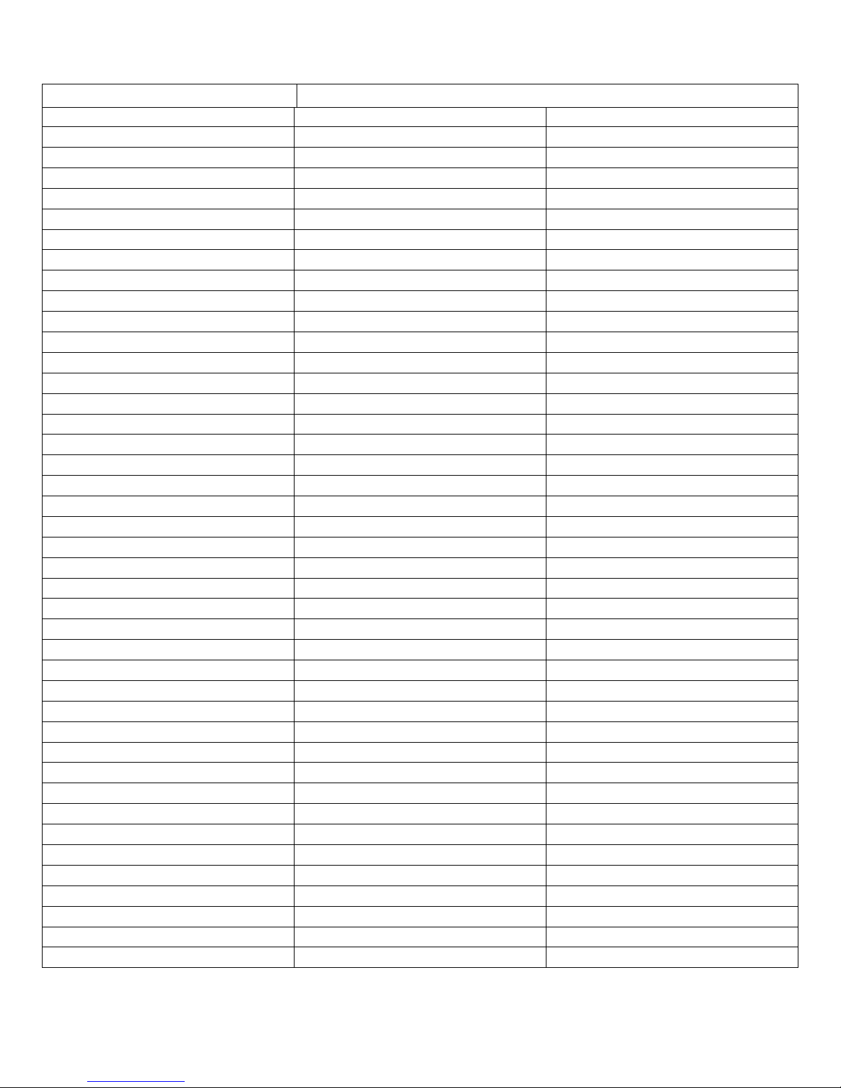
All velocities are approximations:
SOUND VELOCITY MEASUREMENT CHART
Material Sound Velocity
Inch/µS M/s
Air 0.013 330
Aluminum 0.250 6300
Alumina Oxide 0.390 9900
Beryllium 0.510 12900
Boron Carbide 0.430 11000
Brass 0.170 4300
Cadmium 0.110 2800
Copper 0.180 4700
Glass(crown) 0.210 5300
Glycerin 0.075 1900
Gold 0.130 3200
Ice 0.160 4000
Inconel 0.220 5700
Iron 0.230 5900
Iron (cast) 0.180 4600
Lead 0.085 2200
Magnesium 0.230 5800
Mercury 0.057 1400
Molybdenum 0.250 6300
Monel 0.210 5400
Neoprene 0.063 1600
Nickel 0.220 5600
Nylon, 6.6 0.100 2600
Oil (SAE 30) 0.067 1700
Platinum 0.130 3300
Plexiglass 0.110 1700
Polythylene 0.070 1900
Polystyrene 0.0930 2400
Polyurethane 0.0700 1900
Quartz 0.230 5800
Rubber, Butyl 0.070 1800
Silver 0.140 3600
Steel, Mild 0.230 5900
Steel, Stainless 0.230 5800
Teflon 0.060 1400
Tin 0.130 3300
Titanium 0.240 6100
Tungsten 0.200 5200
Uranium 0.130 3400
Water 0.584 1480
Zinc 0.170 4200
• Note: To calibrate the 15947 or 15949 , you must set the velocity to 0.2330/5981M/S (Steel) as stated
in Sect. 7 Calibration, on page 7.
15
 Loading...