

Page 1
INSTALLATION,
OPERATION &
MAINTENANCE
GUIDE
STYLE 58
INTERNATIONAL BRAZIL SOUTHERN USA
HEADQUARTERS REPAIR & SERVICE
1 Jackson Street Rua Javaés, 441/443 1719 South Sonny Avenue
Essex Junction, VT 05452 Bom Retiro, Sao Paulo Gonzales, LA 70737
Brazil CEP 01130-010
TEL: (802) 878-8307 TEL: 55-11-3736-7373 TEL: (225) 484-0007
FAX: (802) 878-2479 FAX: 55-11-3736-7355 FAX: (225) 341-8922
REVISED: February 2019
Page 2
Installation, Operation & Maintenance Guide
Style 58
OVERVIEW
This guide outlines the installation, operation and maintenance of the Flex-A-Seal Style 58 Single Heavy Duty
Stationary Multi-Spring Cartridge Seal. The Style 58 can also be designed to comply with API 682 Standards,
giving it the designation Style 58A. This guide, in addition to the manuals provided by the pump manufacturer
and the manufacturer of any auxiliary equipment, should be read in its entirety prior to installation.
NOTICE
Flex-A-Seal does not assume responsibility for misuse, or any damages incurred as a result of the misuse of the
supplied sealing system. Contact a Flex-A-Seal representative before making any changes to the provided
system or design.
WARRANTY
Flex-A-Seal’s limited warranty covers material defects and workmanship for its goods and/or services for a
period of six (6) months for new items, or three (3) months for repaired items, from the date of their initial
use/installation or delivery, whichever occurs first.
SAFETY
1. Read all instructions thoroughly prior to
beginning installation. Review engineering
prints for special notes and/or instructions.
• Lockout/tagout procedures
• SDS consultation for any hazardous
materials involved
2. Removal, installation, operation, and
maintenance must only be carried out by
qualified personnel who have thoroughly read
all instructions.
3. The seal must only be used for its intended
application. Flex-A-Seal cannot be held liable
for use outside the scope of the recommended
application.
4. Inspect the replacement seal prior to removal
of the old seal or installation of the new seal
using the technical information provided in this
document. Contact a Flex-A-Seal
representative if there are any questions.
5. Follow plant safety regulations and procedures
throughout the disassembly/installation process
including, but not limited to, the following:
Style 58 Maximum Operating Conditions
Temperature 550◦F (290◦C)
Pressure 1200 psi (80 bar)
Speed 10000 fpm (50 m/s)
• Use of proper personal protective
equipment
• Relief of any system pressure and
mechanical energy
6. The following symbols have been used
throughout the document to highlight important
information:
Instructions intended to prevent damage to
the seal or equipment.
Mandatory instructions intended to prevent
personal injury or extensive damage to
equipment.
Information to note while installing, or for
later use.
• Maximum temperature, pressure, and speed indicate operating extremes independently and
do not imply the seal will function at these extremes at the same time. Contact Flex-A-Seal if
in doubt or for special applications.
Page 1 of 6
Page 3
PREPARATION
(B) BORE ID
(A) SLEEVE OD
.030 MIN. x 30°
63
63
63
Installation, Operation & Maintenance Guide
Style 58
• Verify that equipment has been properly
shut off and rendered inoperative according
to plant safety protocol (e.g. lockout/tagout
procedures).
1. Disassemble the pump seal chamber, in
accordance with the pump OEM instructions, to
expose the existing seal.
Document how the seal chamber is
disassembled for re-assembly.
2. Carefully remove the existing sealing device,
taking care not to damage the shaft.
3. Clean the shaft, shaft sleeve (if present), and
seal chamber face of rust, burrs, grit, sharp
edges, and set screw damage using fine emery
cloth. Wipe clean.
Avoid making flat spots or reducing the
shaft diameter.
4. If the pump is equipped with a shaft sleeve,
verify the condition of its O-ring or gasket and
ensure that it is properly located (fully engaged
against step/hook/snap ring).
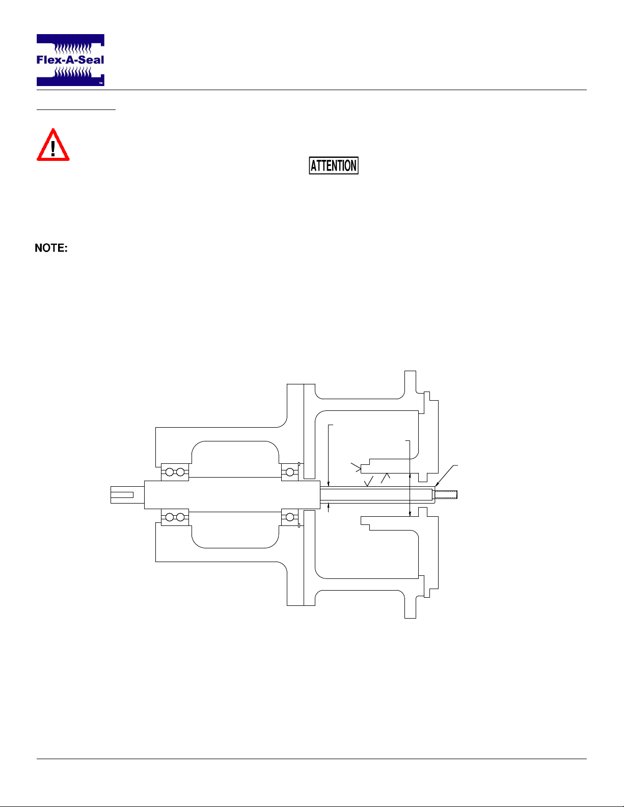
5. Sealing surfaces and the shaft or shaft sleeve
must have at least a 63 Ra-µin surface finish as
seen in Figure 1.
6. For ease of installation, the leading edge of the
shaft or sleeve should be chamfered as shown
in Figure 1 and all parts should be deburred.
Figure 1: Surface finish and chamfer locations. Fully assembled pump without seal.
Page 2 of 6
Page 4
Installation, Operation & Maintenance Guide
Style 58
VERIFICATION
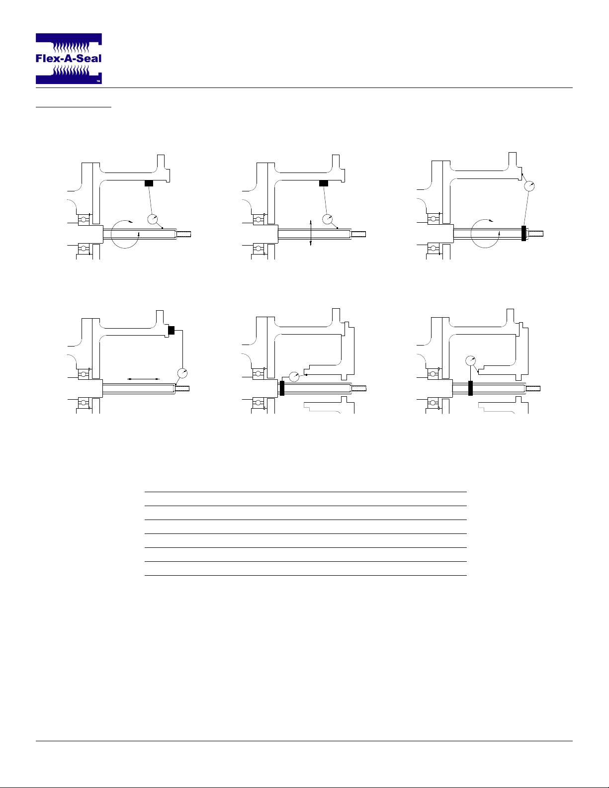
Successful operation of a Style 58 Single Heavy Duty Stationary Multi-Spring Cartridge Seal is contingent on
conforming equipment dimensions and alignment. Verify the following prior to continuing:
Figure 2: Shaft Runout Figure 3: Bearing Fit Figure 4: Bearing Frame
Perpendicularity
Figure 5: Axial Shaft
Movement
Maximum Alignment Variation (TIR)
Fig. 2 Radial shaft movement (shaft runout) 0.0015–0.003 in.
Fig. 3 Radial bearing fit 0.002–0.003 in.
Fig. 4 Bearing frame perpendicularity 0.0005 in./in.
Fig. 5 Axial shaft movement (end play) 0.005 in.
Fig. 6 Seal chamber bore concentricity 0.005 in.
Fig. 7 Seal chamber face squareness 0.0005 in./in.
For proper function and satisfactory operation of the seal it is imperative that connections, dimensions, finishes,
and alignments are all acceptable based on the specified design. If measured values exceed the values given
above, adjust the equipment to meet the specifications before installing the seal. These values are general
guidelines and the pump OEM should be used to verify acceptable values whenever possible.
Figure 6: Seal Chamber
Bore Concentricity
Figure 7: Seal Chamber
Face Squareness
Page 3 of 6
Page 5
SEAL INSTALLATION
Installation, Operation & Maintenance Guide
Style 58
The Style 58 is a highly engineered, heavy duty
stationary multi-spring cartridge seal. It entails the
same simple installation procedure as other
Flex-A-Seal cartridge seals. Ensure alignment
verification of equipment has been completed prior to
starting the installation procedure. Review
engineering prints for special notes and/or
instructions.
• It is essential to use a suitable lubricant
when installing a seal, as different
lubricants will work better with different
elastomers.
1. Disassemble the pump until the seal chamber
and shaft are accessible.
2. Remove the seal from its packaging and
inspect for damage to any components and
seal faces.
Cartridge seals are shipped from
Flex-A-Seal fully assembled and should not
be disassembled without cause. If a seal
appears damaged prior to installation,
contact a Flex-A-Seal representative.
3. Ensure the shaft and seal housing have been
properly cleaned as described in the
preparation section.
4. Lightly lubricate the seal sleeve O-ring with a
suitable and compatible lubricant.
5. Gently slide the seal on the shaft with the gland
gasket facing, but clear of the seal chamber.
6. Reassemble the pump as described by the
pump OEM.
7. Bolt the gland to the seal chamber using the
Legacy Method (Star Pattern) according to
standard torque-tension specifications for bolts
and studs. Be sure not to overtighten the gland
bolts as this may distort the gland and internal
components resulting in seal leakage.
8. Alternately tighten the provided set screws to
the specified torque value according to the
table below.
Grease, scratches, or nicks on the seal
faces may cause leakage.
Cup Point Set Screw Torque Specifications
Screw Size Alloy Steel Stainless Screw Size Alloy Steel Stainless
#10 36 in.-lbs. 26 in.-lbs. M4 2.0 N-m 1.5 N-m
1/4 87 in.-lbs. 70 in.-lbs. M6 7.9 N-m 6.1 N-m
5/16 165 in.-lbs. 130 in.-lbs. M8 19.6 N-m 15.4 N-m
3/8 290 in.-lbs. 230 in.-lbs. M10 37.0 N-m 29.5 N-m
1/2 620 in.-lbs. 500 in.-lbs. M12 60.3 N-m 48.3 N-m
9. Remove the setting clips from the seal. Save
these for future use in seal removal or impeller
adjustment.
Page 4 of 6
Page 6
BEFORE STARTING THE EQUIPMENT
1. Ensure the pump shaft is properly aligned at
the coupling with the motor.
2. Check that all gland plate bolts and all screws
are securely fastened.
Installation, Operation & Maintenance Guide
Style 58
6. Ensure all plumbing and venting are free of
obstruction and that the chamber is filled with
liquid. Check that all alarms connected to
auxiliary systems are properly functioning to
alert personnel if any issues arise.
3. Once the pump is reassembled, turn the shaft
by hand if possible to check for free rotation, if
not, recheck installation.
4. Verify that all plumbing and piping plans for the
seal are connected and configured according
to best practice.
5. Flood the pump, vent all air from the seal
chamber, and check the seal for leakage.
OPERATION & MAINTENANCE
If leakage is detected, it should be addressed as soon as possible to prevent hazards and protect personnel.
Leakage could come from a number of leak paths in the seal, or be caused by changes in the pump operation or
condition. Although seals should be inspected regularly for signs of leakage, a properly selected and functioning
mechanical seal will run for extended durations without need for extra attention and should not be disturbed
unnecessarily (i.e. shut down and disassembled without cause). Below is an inexhaustive list of possible causes
of leakage.
Primary Causes
• Worn seal faces
Dry-running is a major cause for leakage
and/or failure of mechanical seals. It is
imperative that the seal chamber be
completely vented prior to startup and that
adequate lubrication is supplied to the seal.
7. Start the pump per the pump manufacturer’s
recommendations, observe for proper
operation, and check for excessive heat at the
seal gland.
Check periodically during operation to
ensure that the seal is not overheating.
Secondary Causes
• Change in duty conditions
• Damaged O-rings
• Damaged springs
It is important to periodically inspect and maintain flush systems, shaft alignment, and consistent duty
parameters to ensure the seal performs as designed. Often, there is a case of cause & effect with machinery
and processing issues upstream that can cause a seal to leak. Check for the root cause of leakage when
disassembling equipment for inspection or service.
DECOMMISSIONING EQUIPMENT
When decommissioning equipment it is important to ensure that the pump has been fully isolated from the
process and power sources for personnel safety. Pressure and fluid should be fully released before disassembly
of the equipment is to begin.
• If the equipment has been used with toxic or hazardous fluids, ensure that it is
decontaminated and neutralized before decommission begins. There is often residual fluid
remaining from the draining process so consult the pump OEM for special cases.
• Dry-running
• Worn bearings
• Increased vibration
Page 5 of 6
Page 7
Installation, Operation & Maintenance Guide
[F] [D][V]
Style 58
REMOVING THE SEAL
• Before opening the pump to remove the seal the warning stated above regarding toxins and
hazardous products must be reiterated. Make note of all fluids contained in the pump, drain
and decontaminate before opening the housing for seal service.
1. Ensure all fluid has been drained and vented. Equipment should be shut down and locked/tagged out
according to OEM and plant specifications.
2. Dismantle equipment sufficiently so that the gland plate and seal housing are exposed and accessible for
service.
3. Reset the setting clips that were saved from installation.
4. Back-out the cup point set screws.
5. Remove the gland bolts/nuts in an even manner.
6. Carefully slide the seal out and off of the shaft.
If a part is going to be returned for service or to any third party, all shipments should have
appropriate safe-handling instructions securely attached to the package.
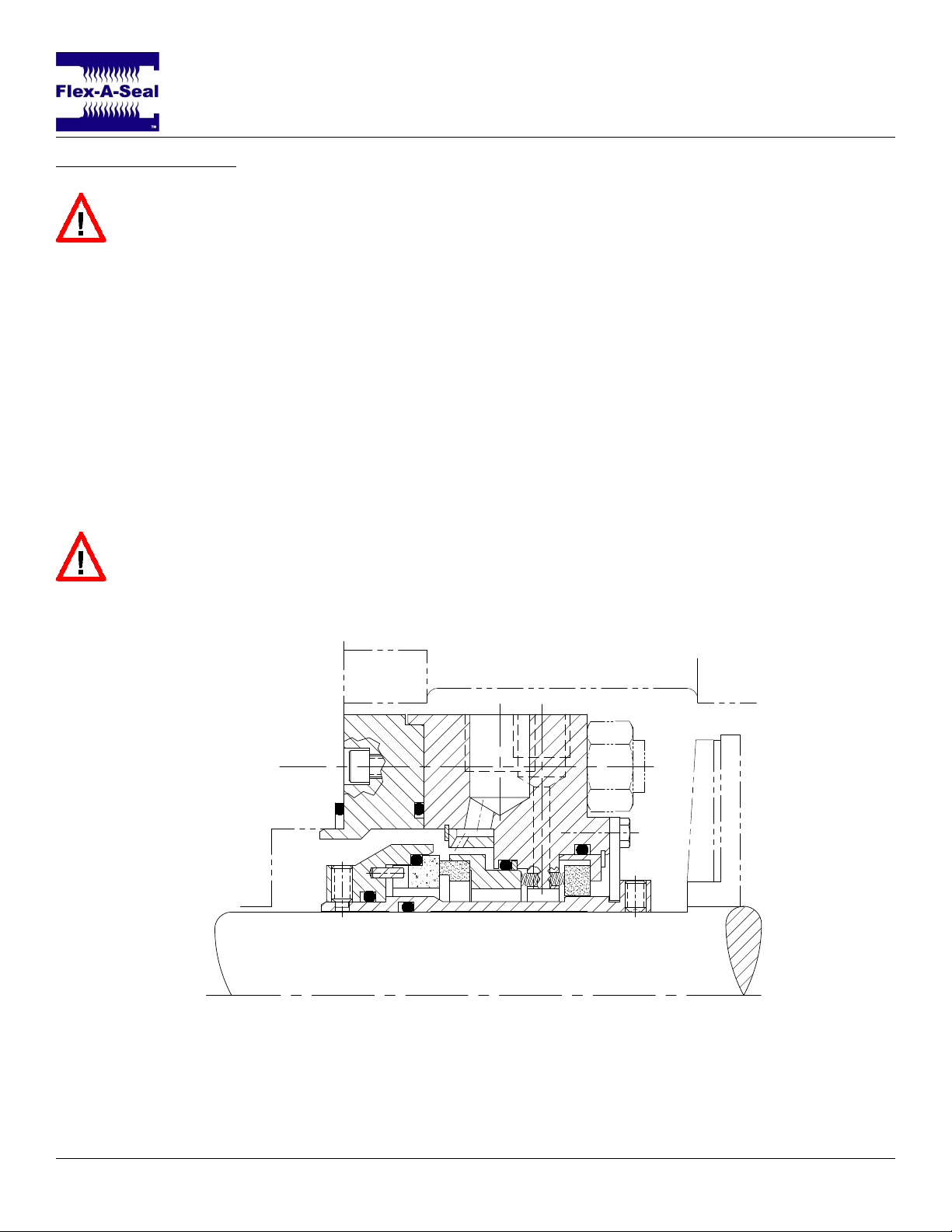
Figure 8: Style 58A with multipoint injection and a floating carbon throttle bushing.
Page 6 of 6
 Loading...