

Page 1
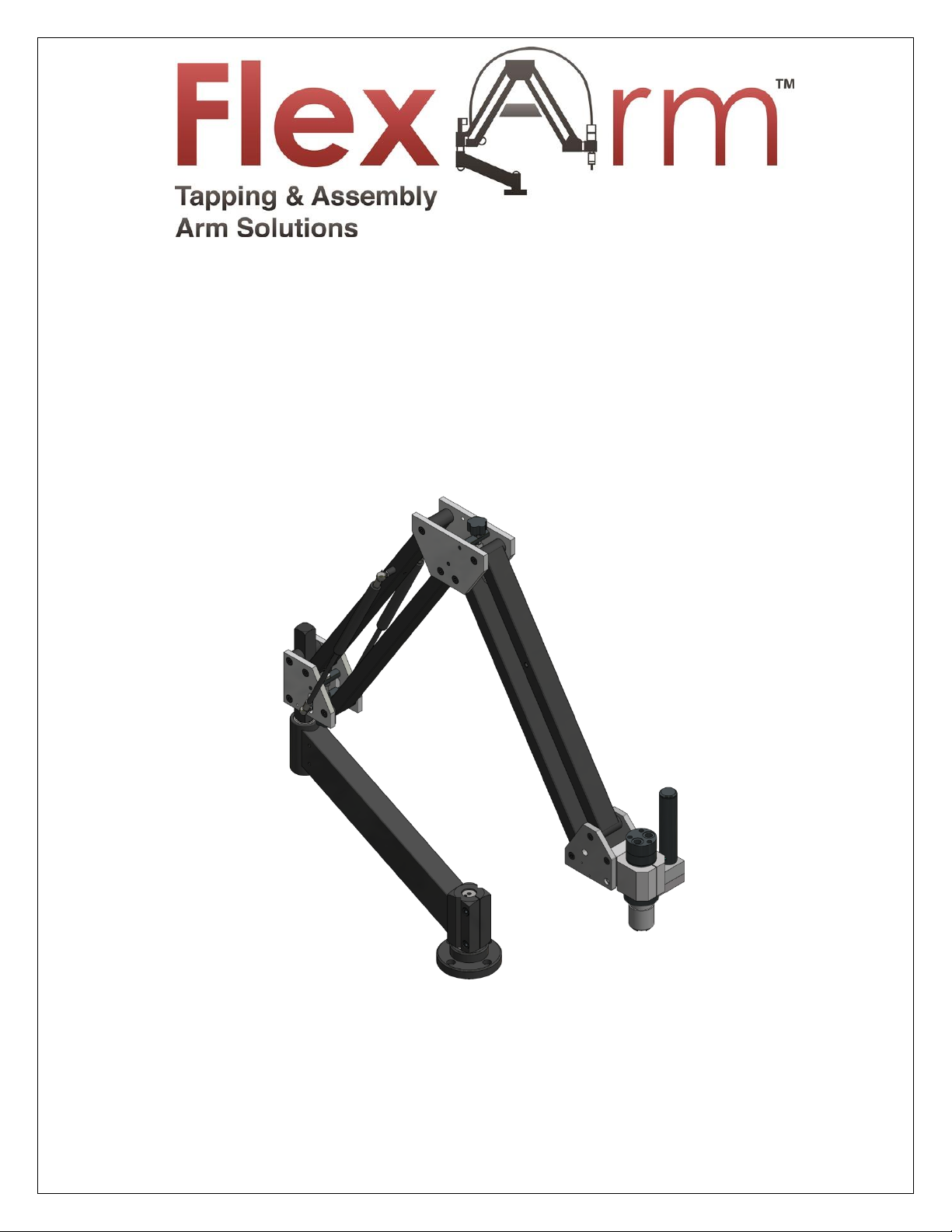
GH-24, GH-30, GH-45, GH-60
INSTALLATION & OPERATIONS
MANUAL
1 of 59 GH-24, GH-30, GH-45, GH-60 Rev.003
FlexArm Inc.
Division of Midwest Specialties, Inc.
851 Industrial Drive
Wapakoneta, Ohio 45895
419-738-8147
800-837-2503 (toll free)
www.flexarminc.com
Page 2

2 of 59 GH-24, GH-30, GH-45, GH-60 Rev.003
Page 3

TABLE OF CONTENTS:
Safe Operation: READ THIS FIRST - - - - - - - - - - - - - - - - - - -
4
Warranty - - - - - - - - - - - - - - - - - - - - - - - - - - - - - - - - - - - - -
5
Technical details -- - - - - - - - - - - - - - - - - - - - - - - - - - - - - - -
6-7
Installation - - - - - - - - - - - - - - - - - - - - - - - - - - - - - - - - - - -
8-11
Start Up/Shut Down Procedure - - - - - - - - - - - - - - - - - - - - -
12-14
Tap Lubricator System - - - - - - - - - - - - - - - - - - - - - - - - - - -
15
Multi Position Head - - - - - - - - - - - - - - - - - - - - - - - - - - - - -
16-17
Operating Instructions - - - - - - - - - - - - - - - - - - - - - - - - - - -
18-19
Adjusting Tap Holder Torque Settings - - - - - - - - - - - - - - - -
20
Counterbalance Adjustment - - - - - - - - - - - - - - - - - - - - - - -
21
Parts Breakdown - - - - - - - - - - - - - - - - - - - - - - - - - - - - - - - -
20-46
Removing the Chuck - - - - - - - - - - - - - - - - - - - - - - - - - - - -
47
Cylinder Replacement - - - - - - - - - - - - - - - - - - - - - - - - - - - -
48-51
Hydraulic Gear Box Disassembly - - - - - - - - - - - - - - - - - - - -
52
Maintenance - - - - - - - - - - - - - - - - - - - - - - - - - - - - - - - - - -
53-54
Troubleshooting - - - - - - - - - - - - - - - - - - - - - - - - - - - - - - - -
55-58
Alignment Check List - - - - - - - - - - - - - - - - - - - - - - - - - - - - -
59
3 of 59 GH-24, GH-30, GH-45, GH-60 Rev.003
Page 4

SAFE OPERATION: READ THIS FIRST
Read the entire unit manual before operating.
o Wear eye protection when operating this equipment.
o Do not wear jewelry or loose clothing when operating.
o Tie hair back before operating machine.
o Do not wear gloves when operating this equipment.
o Do not use damaged, frayed, or deteriorated air hoses or fittings.
o Removing the tool or weight from the arm will allow the arms to extend rapidly, possibly causing
damage or injury.
o Keep hands clear of the motor chuck and tap when actuating the motor.
o Keep hands free of pinch points on the unit when operating.
o Perform regular maintenance according to the manual, including filling the motor lubricator with
correct oil and greasing the motor gears.
o Do not alter or modify the motor or unit.
o Periodically inspect for damage, loose hardware or anything irregular.
o Read the FlexArm warranty page before performing any maintenance or repairs.
o Do not exceed the torque or weight limitations for the unit. Doing so will void the warranty and
possibly cause damage or injury.
o It is imperative that the table or mounting surface be lagged to the floor and secure before installing
the FlexArm Hydraulic Tapping Machine.
o If the Hydraulic Tapping Machine is going to be lifted with a crane, please call FlexArm for special
instructions.
o FlexArm is not responsible for accident or injury resulting from the misuse of this unit or for use other
than originally designed and intended.
Caution: Always secure the work piece to the table before operating the machine!
This machine is designed for tapping, chamfering, and light reaming of holes.
Safety Standards
o The oil hoses & fittings can tolerate at least 250 Bar, and have a breakage of pressure above 350 Bar.
The necessity of maximum pressure is from 100 to 120 Bar and the safety valve doesn't permit excess
of 140 Bar, these must be replaced every 10 years or if some malfunction is detected by others with
similar characteristics.
o The work pieces must be firmly held in place to avoid breakage of taps or of striking the operator. The
operator doesn't have to wear special clothes but protection glasses must be worn.
o When the machine is installed, connect it to the ground clamp system before operating.
o For every adjustment to this machine, the master switch must be disconnected and the work carried
out by electricians.
4 of 59 GH-24, GH-30, GH-45, GH-60 Rev.003
Page 5
FLEXARM LIMITED WARRANTY
What does a FlexArm Warranty Cover
The repair or replacement of the FlexArm product if it is found to be defective due to faulty materials,
workmanship or function within the guarantee period of 3 years. (if any part is no longer available or out of
manufacture, FlexArm will replace it with a functional replacement part). The warranty is based off normal
usage, or equivalent to a 40-hour work week.
What is not covered by a FlexArm Warranty
FlexArm Inc shall not be liable for costs of repair or replacement of a product incurred as a result of:
o A FlexArm product that has had the serial number altered or removed.
o Cylinders with scratches or marks on the shaft.
o Handling of the product which is not in accordance with the product manual.
o Damage as a result of using the unit over its stated capacities.
o FlexArm products not purchased direct or from an authorized dealer.
o Use of parts and accessories other than those produced or recommended by FlexArm.
o Improper maintenance or lack of maintenance per the manual.
o Damage from external sources such as transit, weather, electrical outages, power surges, or bad air
quality (compressor).
o In Air Motors: Filters, Springs, Blades/Vanes, O-Rings are not covered.
o Repairs or alterations carried out by parties other than FlexArm or its authorized distributors.
o Tap Holders and Helicoil components do not carry a warranty.
Warranty Service
Before service can take place, the terms of the limited warranty require that you contact FlexArm with your
model, serial number, and date of purchase. Please keep your purchase receipt in a safe place to ensure you
have this information. The serial number is found on the FlexArm’s side plate.
An RGA must be obtained from a FlexArm Customer Service Representative.
All work will be coordinated by FlexArm or its authorized distributors.
Any replaced defective parts must/will become the property of FlexArm.
Service under this warranty will not extend the period of this warranty. If your FlexArm is not functioning properly,
please call FlexArm at 1-800-837-2503. Most issues can be rectified over the telephone by our trained Customer Service
Department.
5 of 59 GH-24, GH-30, GH-45, GH-60 Rev.003
Page 6
TECHNICAL DETAILS
TECHNICAL DETAILS CHART
MODEL
GH-24
GH-30
GH-45
GH-60
Electric Motor (HP)
5.5
5.5
5.5
5.5
Best Maximum Pressure (Bar)
120
120
120
120
Security Maximum Pressure (Bar)
140
140
140
140
Min Thread Capacity
#6
#6
¼”
¼”
Max Thread Capacity
7/8”
1-1/4”
1-1/2”
2”
RPM
100-500
140-500
110-500
55-275
Oil Tank Capacity (Gallons)
9
9
9
9
Max Torque (Ft/lbs)
78/63
188/63
325/63
811/162
6 of 59 GH-24, GH-30, GH-45, GH-60 Rev.003
Page 7
TECHNICAL DETAILS
MANUFACTURER
BP/VERKOL
MOBIL SHELL
CASTROL EXXON
GULF TEXACO
HYDRASIL 46 AW
RANDO OIL HD 46
BRAND NAME
ENERGOL HLP 46
DTE 25
TELLUS 46
HYSPIN AWS 46
NUTO HP 46
Hydraulic Oil
o This unit has been factory tested and is s hipped with hydraulic oil in the tank. The tank holds a
maximum of 9 gallons of hydraulic oil. Check the oil level on the oil level/temperature gauge on
the front of the power pack.
The following (ISO Grade 46 compatible) hydraulic oils are recommended for use in the FlexArm
Hydraulic Tapping Machines:
WARNING!
Do not operate the machine the oil level is BELOW the RED DOTTED LINES on the oil level/temperature gauge.
Do not add oil while the machine is operating. Turn off the machine, disconnect the power supply and allow
the unit to cool down to 80 degrees or less before adding more hydraulic oil
To add oil, unscrew the cap on the oil tank at the back of the power pack. Using a funnel with a flexible
spout, pour the oil slowly into the tank and check the oil level/temperature gauge as it is being added. DO
NOT FILL ABOVE THE BLACK DOTTED LINES AT THE TOP OF THE OIL LEVEVTEMPERATURE GAUGE.
7 of 59 GH-24, GH-30, GH-45, GH-60 Rev.003
Page 8
ELECTRICAL INSTALLATION
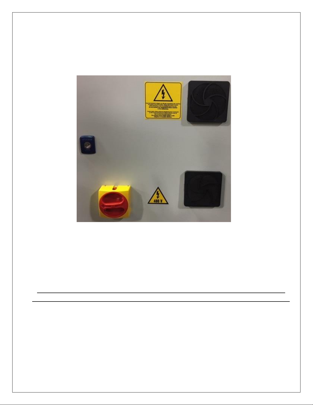
First ensure what voltage your unit is pre wired for, either 220V or 480V. This will be clearly indicated on
the rear electrical panel on the outside of unit. An example of a 480V unit is shown below with the voltage
sticker next to the master switch.
Connect the machine to a grounded, 3 phase electric supply. The circuit should be protected with a 20
amp circuit breaker if the unit is wired for 480v and 30 amps if it is wired for 220v. This unit does not come
with a plug.
CAUTION: When making repairs to this unit, always disconnect the main power supply. Additionally,
hooking up incorrect power supply could result in damage to the unit and void any existing warranty.
Please Contact FlexArm with any questions or concerns about the installation of the FlexArm hydraulic tapping machine at
800-837-2503
8 of 59 GH-24, GH-30, GH-45, GH-60 Rev.003
Page 9
ARM INSTALLATION
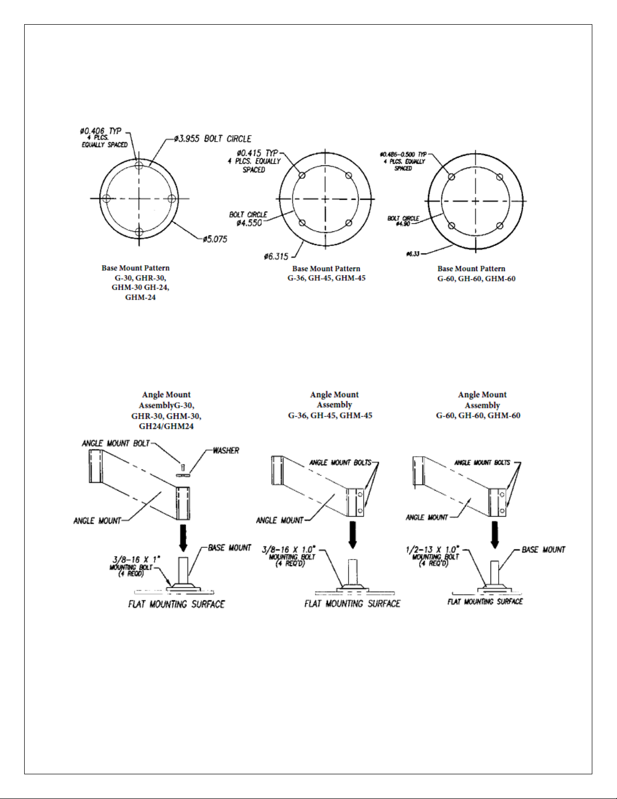
1. Drill and tap 4 bolt holes on a flat, smooth table or work bench. Use 3/8-16 bolts for the 24, 30, and 45
series units. Use 1/2-13 bolts on the 60 series units. (See Base Mount diagram below)
2. Secure the base mount and apply a light coating of grease to the base mount shaft. Slide the angle
mount onto the shaft of the base mount and secure the angle before inserting the FlexArm! (See Angle
Mount Assembly Diagram Below)
9 of 59 GH-24, GH-30, GH-45, GH-60 Rev.003
Page 10
ARM INSTALLATION
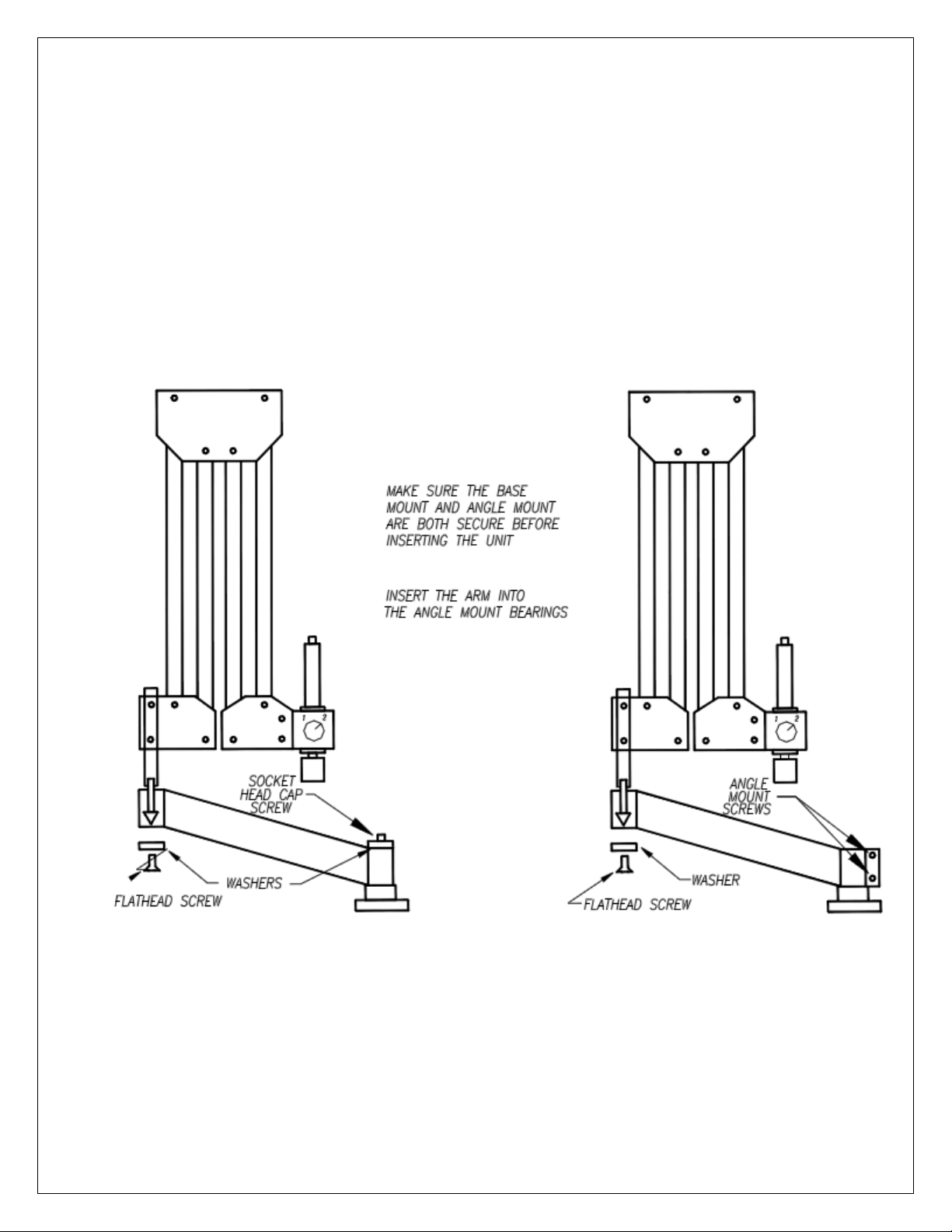
3. Secure the angle mount by placing the washer on top of the lower bore and tightening the angle
mount bolt securely into the base mount for a GH-24 and GH-30. For the GH-45 and GH-60 tighten the
two angle mount screws. The angle mount bolts must be tightened securely or the machine will not
maintain perpendicularity.
4. Insert the rear pin of the unit into the upper bore and bearing of the angle mount. The rear pin may
not slide through both bearing sets- use the flathead cap screw to help pull the unit completely
through the bottom bearing.
5. Remove any straps holding the arms together and adjust the counter balance of the arm. This will
eliminate the possibility of the arm striking the operator when it is positioned at its lowest point. (See
Counter Balance Adjustment Section on page 21)
10 of 59 GH-24, GH-30, GH-45, GH-60 Rev.003
Page 11
ARM TO POWER PACK INSTALLATION
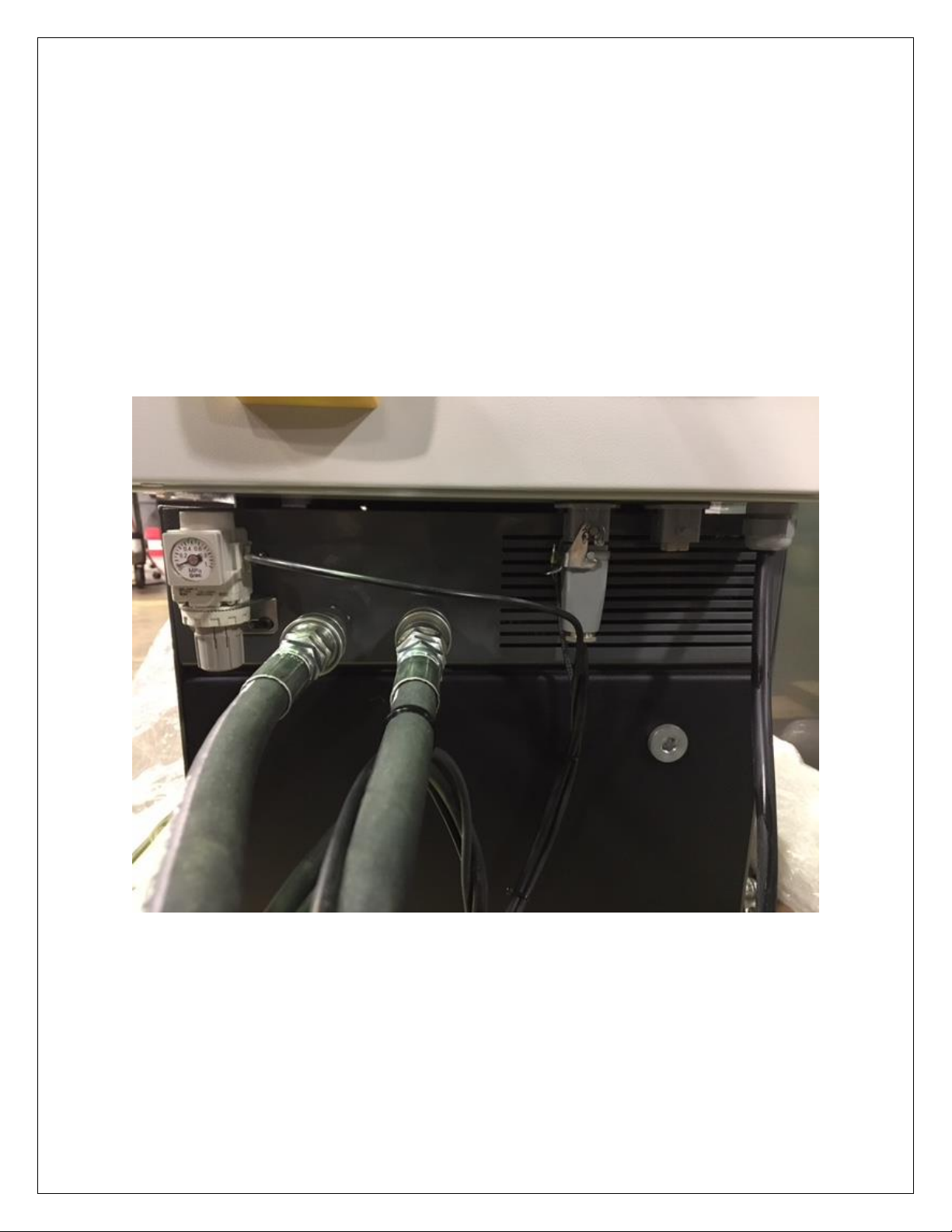
1. After the FlexArm is securely fastened to its mounting surface it can be hooked up to the power pack.
2. First, connect the two hydraulic hoses on the arm to the quick-disconnect hose couplings on the power
pack. There should be a male and female fitting.
3. Next attach the male four pin connector on the arm to the left female receptacle on the power pack.
There should be a locking clip on the female receptacle notating the proper one to attach to.
4. The four pin female connecter on the right is only to be used with arms adapted with digital depth
control (Instructions for digital depth control are found in a separate manual).
5. Lastly the air line can be connected to the regulator-manometer shown on the far left. This is to be
used with units that have the semi-tap lubricator option (Instructions for this option to be found on
page 15).
11 of 59 GH-24, GH-30, GH-45, GH-60 Rev.003
Page 12
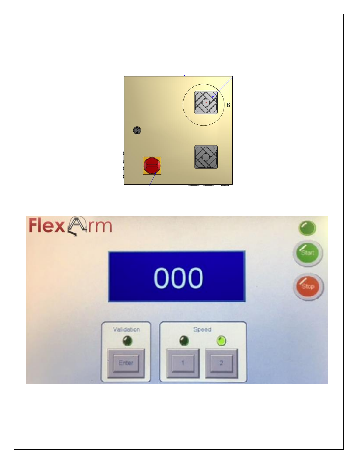
START UP PROCEDURE
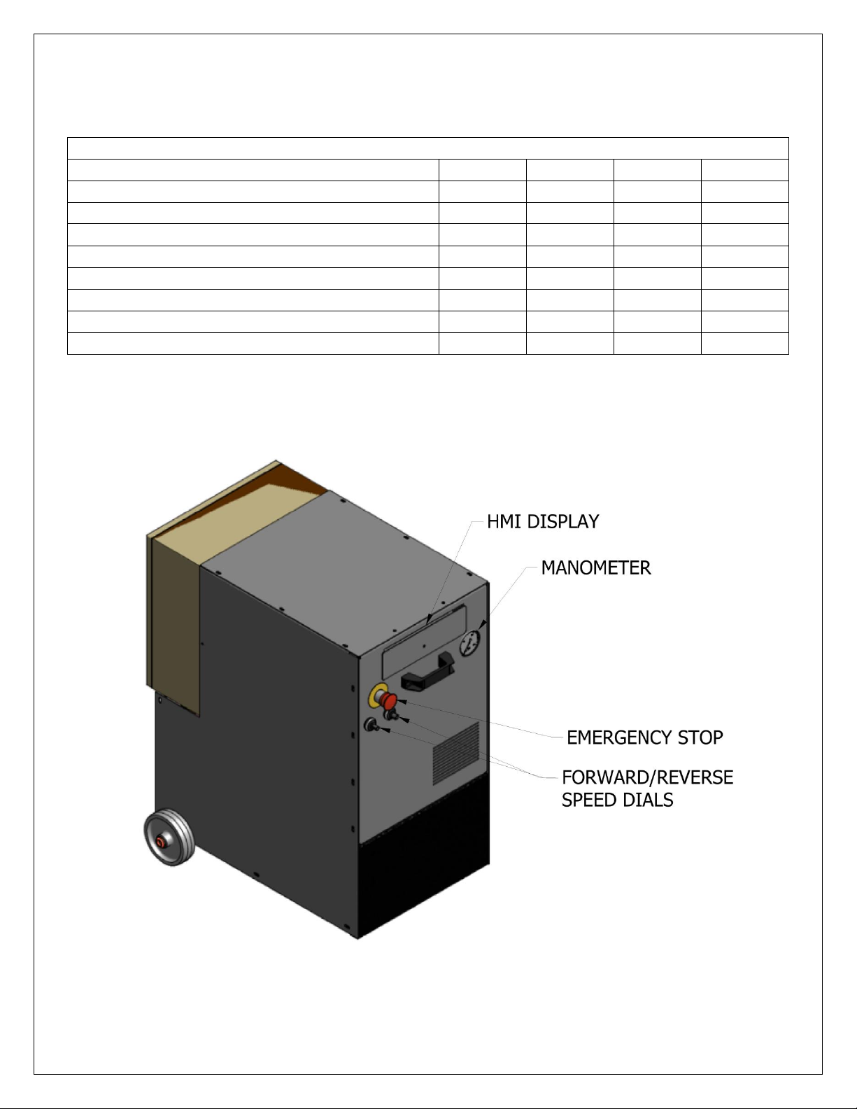
1. Plug the unit in and turn on the red master switch on the rear of the unit. Ensure the emergency stop
on front of the unit is pulled out and not engaged.
2. Pull out the front HMI display and wait for it to boot up. It should display as below:
12 of 59 GH-24, GH-30, GH-45, GH-60 Rev.003
Page 13
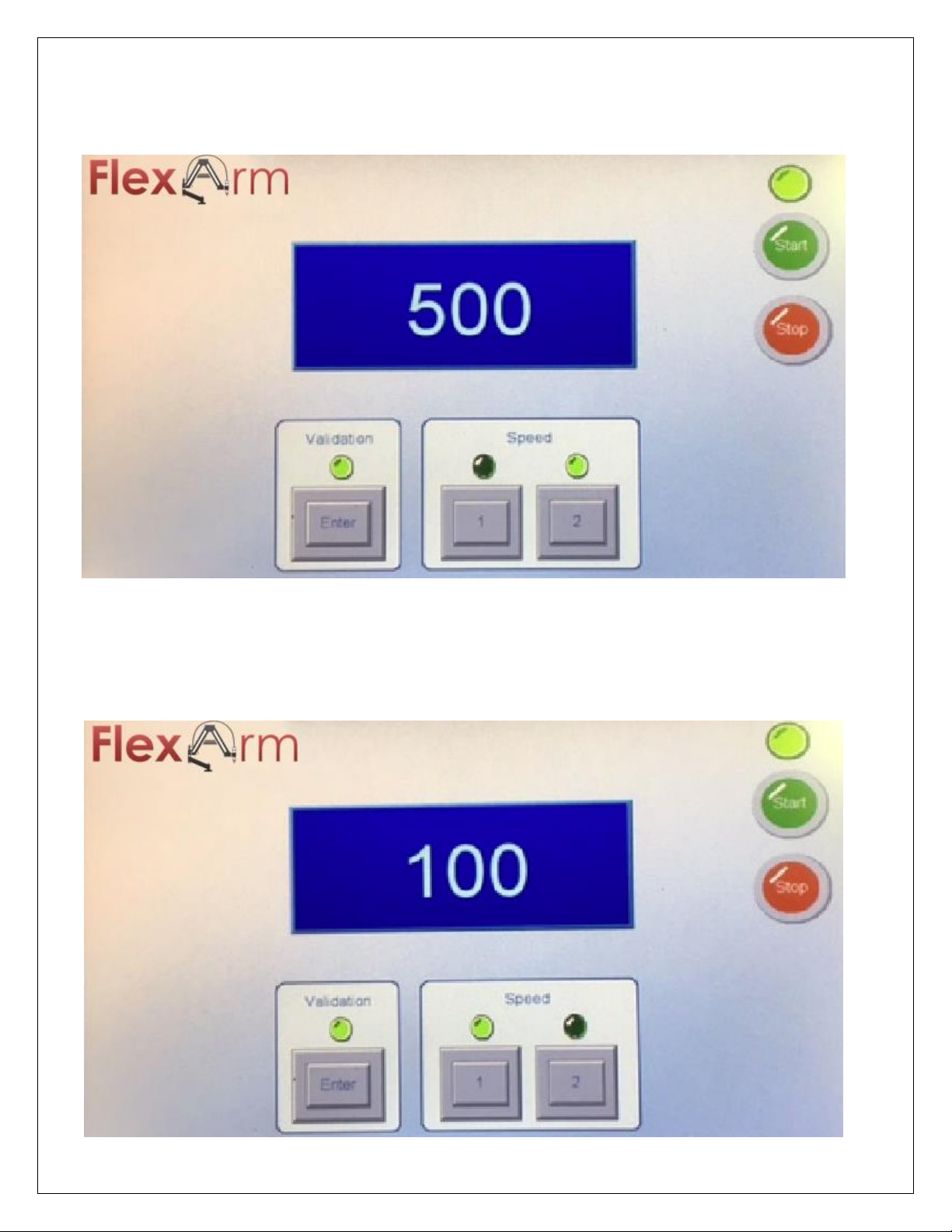
3. To turn the motor on press the green start button.
4. Next, you need to confirm you are in the proper gear setting on both the arm’s gearbox and the
display; in this case gear two.
5. Once you confirm the gear settings match, press validation and you can begin tapping.
6. When switching gears, once again validate you are in the proper gear setting on both the arm’s
gearbox and the display. You will need to re-press the validation button before you begin tapping
again.
13 of 59 GH-24, GH-30, GH-45, GH-60 Rev.003
Page 14

SHUT DOWN PROCEDURE
1. Press the red stop button on the HMI to simply turn the motor off if it doesn’t need to be used for a
short period of time.
a. If the unit is left on for a short period of time without being used it will enter sleep mode and
turn off by itself.
2. The master switch only needs to be switched off if the unit will not be used for a longer period of time.
a. Before turning off the master switch press the red stop button on the HMI and allow the motor
in the power pack to completely spool down.
IMPROPER SHUTDOWN
Turning the machine off with the master switch before turning off the machine with the red button.
Turning the master switch off before the motor in the power pack has spooled down completely.
(approximately 3 seconds)
Suddenly removing power from the machine i.e. pulling the plug out of the wall before turning off the
machine with the red button.
Unplugging the unit before the motor in the power pack has spooled down completely. (approximately
3 seconds)
Pressing the green button while master switch is off and residual power is still in the inverter
(approximately 45 seconds after shutdown)
IF IMPROPER SHUTDOWN OCCURS
1. Reset the power pack by turning the master switch off.
2. Unplug the machine (wait 45 seconds to allow the inverter to reboot)
3. Plug the machine back in
4. Re-follow the steps in the startup procedure.
14 of 59 GH-24, GH-30, GH-45, GH-60 Rev.003
Page 15
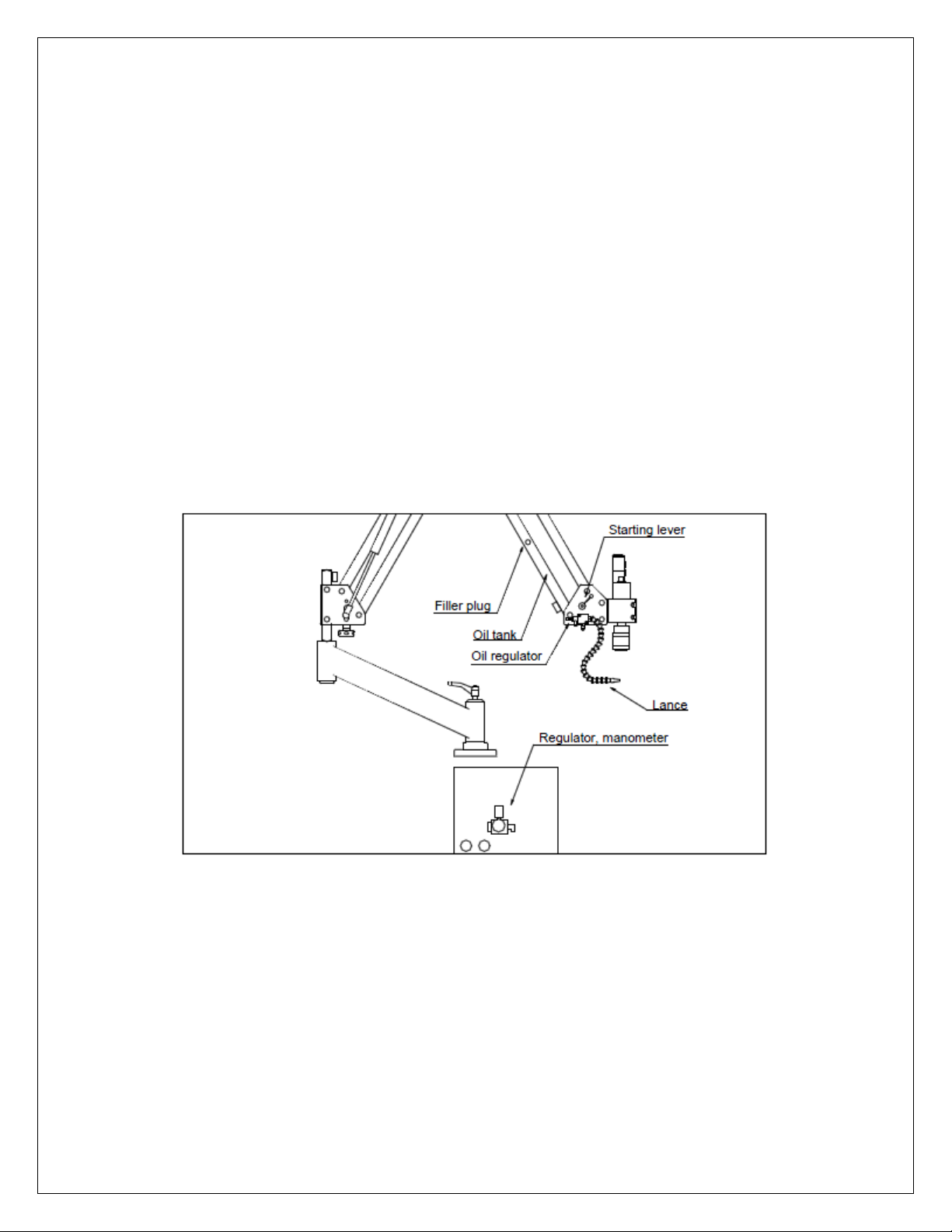
USE OF TAP LUBRICATOR SYSTEM
FlexArm includes a standard tap lubricator system on its tapping units. [Refer to diagram]
Ensure the air inlet and the arm’s air tube is connected to the regulator-manometer which is adjusted in
our factory.
Fill oil tank located in front lower arm: uncover the filler plug and fill with tapping oil to the maximum
level.
Press and hold the starting lever until you see atomized oil begin to leave for the lance tip. The first time,
the atomized oil will take time to reach the lance tip, but later uses will be much quicker.
Adjust the quantity of oil mixture released by adjusting the oil regulator mounted behind the lance.
The tap lubricator system can be used before, during and after tapping pieces.
Caution! Don´t use corrosive oil, it can damage the system's plastic valves.
15 of 59 GH-24, GH-30, GH-45, GH-60 Rev.003
Page 16
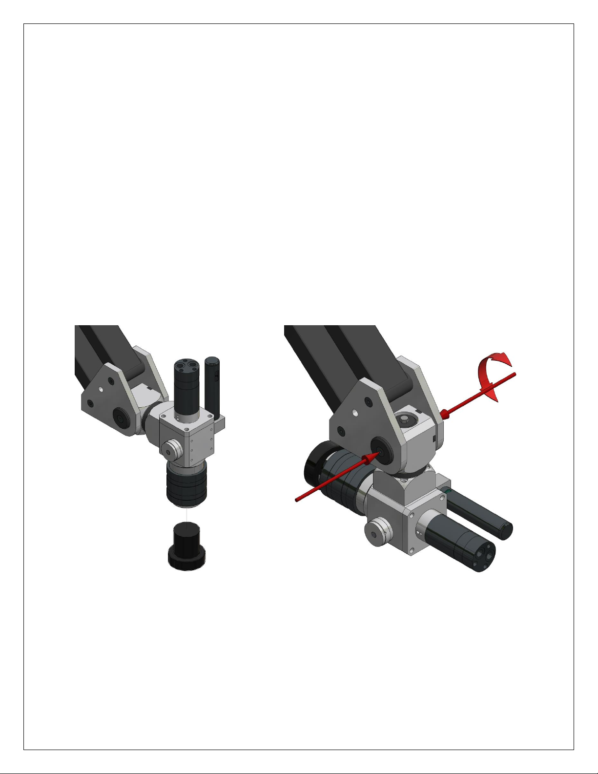
USE OF MULTI-POSTION HEAD
Figure 1
Figure 2
Items needed:
o Adjustable wrench and or socket.
o Metric Allen wrench set
o Magnetic plug
NOTE: The GHM-24 has handles instead of bolts so no tools are needed.
Please follow the steps below to switch from vertical tapping to horizontal tapping.
1. Insert the magnetic plug into the chuck (Figure 1).
2. Next you will need an adjustable wrench or socket and a metric Allen wrench to loosen the two bolts
on the side plates and move the head down into horizontal orientation (Figure 2).
3. Leave these bolts on the side plates loose.
4. When the head is used as shown in figure 2 and figure 3 you will need to break loose the hex head bolt
on top. A wrench or socket will be needed for this.
16 of 59 GH-24, GH-30, GH-45, GH-60 Rev.003
Page 17
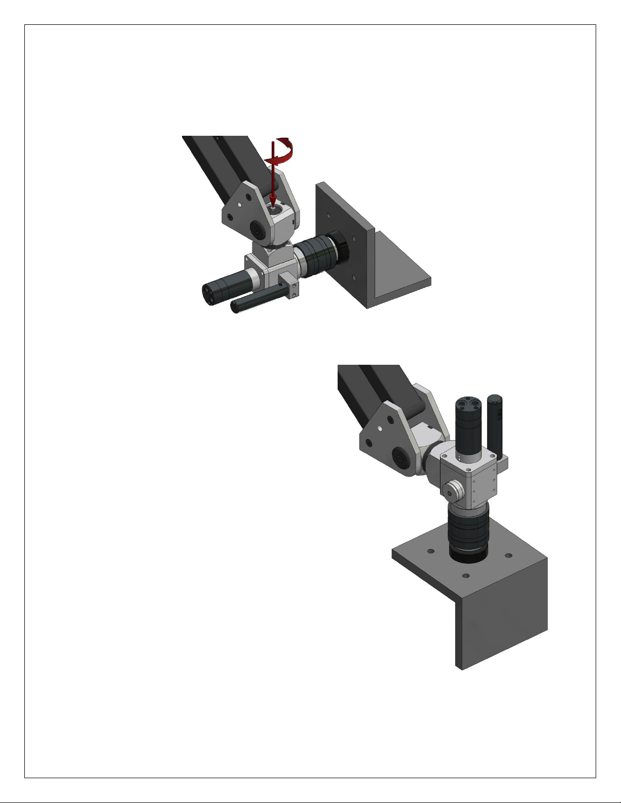
5. With both rotations now free, align the magnetic plug to the horizontal work surface (Figure 3). Once
Figure 4
Figure 3
the magnetic plug is locked on to the horizontal surface, the bolts on the side plates can be completely
tightened down.
6. The top bolt needs to be kept loose when tapping in the horizontal orientation.
7. Now that the unit is aligned, the magnetic plug can
be removed and the desired tap can be inserted
into the chuck. The unit is now ready to be used for
horizontal tapping.
8. To get back to vertical tapping remove the tap and
re-insert the magnetic plug.
9. Loosen the bolts on the side plates, the top bolt
should already be loose, and realign the magnetic
plug to the vertical surface (Figure 4).
10. Completely tighten down the two side plate bolts
and the top bolt, which is now between the side
plates facing the rear.
11. Remove the plug and re-insert the proper tap and
begin tapping.
NOTE: The multi-positional head allows taping in additional positions. This kind of tapping doesn't
guarantee the perfect thread but will provide a good tapping quality.
17 of 59 GH-24, GH-30, GH-45, GH-60 Rev.003
Page 18
OPERATING INSTRUCTIONS
1. Always wear safety glasses and use proper safety precautions when operating this unit. Gloves are not
recommended when operating this machine.
CAUTION: ALWAYS SECURE THE WORK PIECE TO THE TABLE BEFORE OPERATING THIS MACHINE
2. Select the correct tap holder for the tap size required. Insert the tap into the holder by depressing the
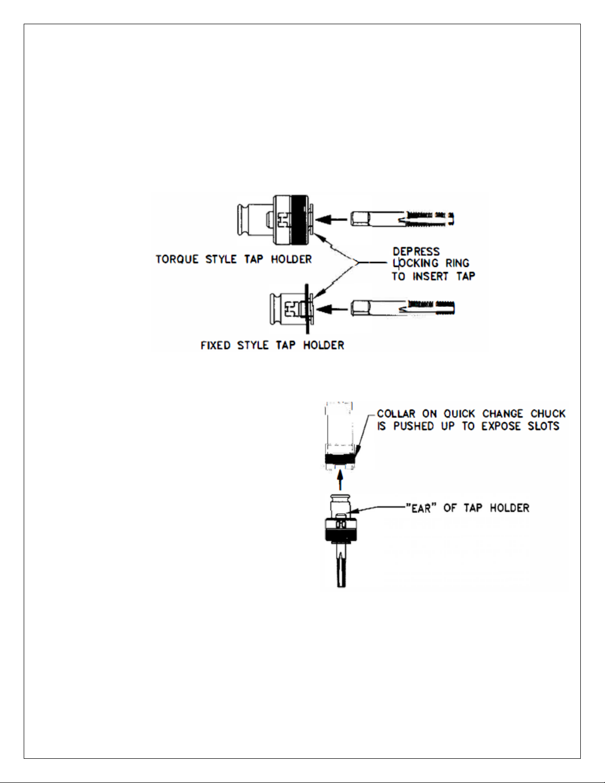
locking ring. Seat the top square into the tap holder; release the locking ring.
3. Push up on the collar of the quick change chuck before inserting the tap holder.
4. Insert the tap holder into the quick change chuck.
Turn the holder until the "ears" of the holder
locate the slots of the chuck. Push up to lock the
holder into position.
5. Position the hydraulic motor vertically above the
hole being tapped. There can be no obstruction
that interferes with the downward path of the
tap holder or prohibits the tap from completing
the required thread depth.
6. Actuate the hydraulic motor by depressing the
forward button and gently guide the tap down to the hole (typically use lower gear; slow speed, for
larger tap sizes).
18 of 59 GH-24, GH-30, GH-45, GH-60 Rev.003
Page 19

OPERATING INSTRUCTIONS
7. EXERT ONLY ENOUGH DOWNWARD PRESSURE TO START THE TAPPING PROCESS. The tap will engage
itself and follow the hole. When tapping a through hole, remember that the tap will protrude on the
bottom side of the workpiece; make sure there is sufficient clearance below the work piece to allow
the tap to break through and not hit the work surface. Use a torque style tap holder when tapping
blind or bottom holes. The built-in safety clutch on this holder will ratchet and stop the tap from
turning when the tap has reached the bottom of the hole.
8. When the hole is completely tapped, release the forward button and actuate the reverse button to
change the rotation of the hydraulic motor and remove the tap from the hole.
DO NOT PUSH OR PULL ON THE MOTOR AS THE TAP IS TAPPING THE HOLE OR
BACKING OUT OF IT! THIS RESULTS IN POOR THREAD QUALITY, OVERSIZED THREADS.
AND BROKEN TAPS!
9. To change tap holders, release the tap holder by pushing up on the collar of the quick change chuck.
19 of 59 GH-24, GH-30, GH-45, GH-60 Rev.003
Page 20
ADJUSTING TAP HOLDER TORQUE SETTING
The torque adapters are factory preset near the standard break torque limits developed for each tap size. The
break torque limit protects the tap when tapping blind or bottom holes in mild steel (approximately 229 BHN
or 25 RC). When the tap reaches the bottom of the hole, resistance will cause the torque holder’s safety clutch
to ratchet and stop the tap from turning, over-torqueing and ultimately breaking. When tapping hardened
steel (above 40 RC), stainless steel, or other tough alloys, an increase in the factory torque setting may be
required in order to drive the tap the full depth of the hole. When using the torque adapters to tap soft
materials or plastics, a decrease in the factory torque setting prevents the tap from over-torqueing after it
reaches the bottom of the hole.
Caution: Never adjust the torque setting more than one (1) notch at a time. Adverse tapping conditions and
broken taps may result!
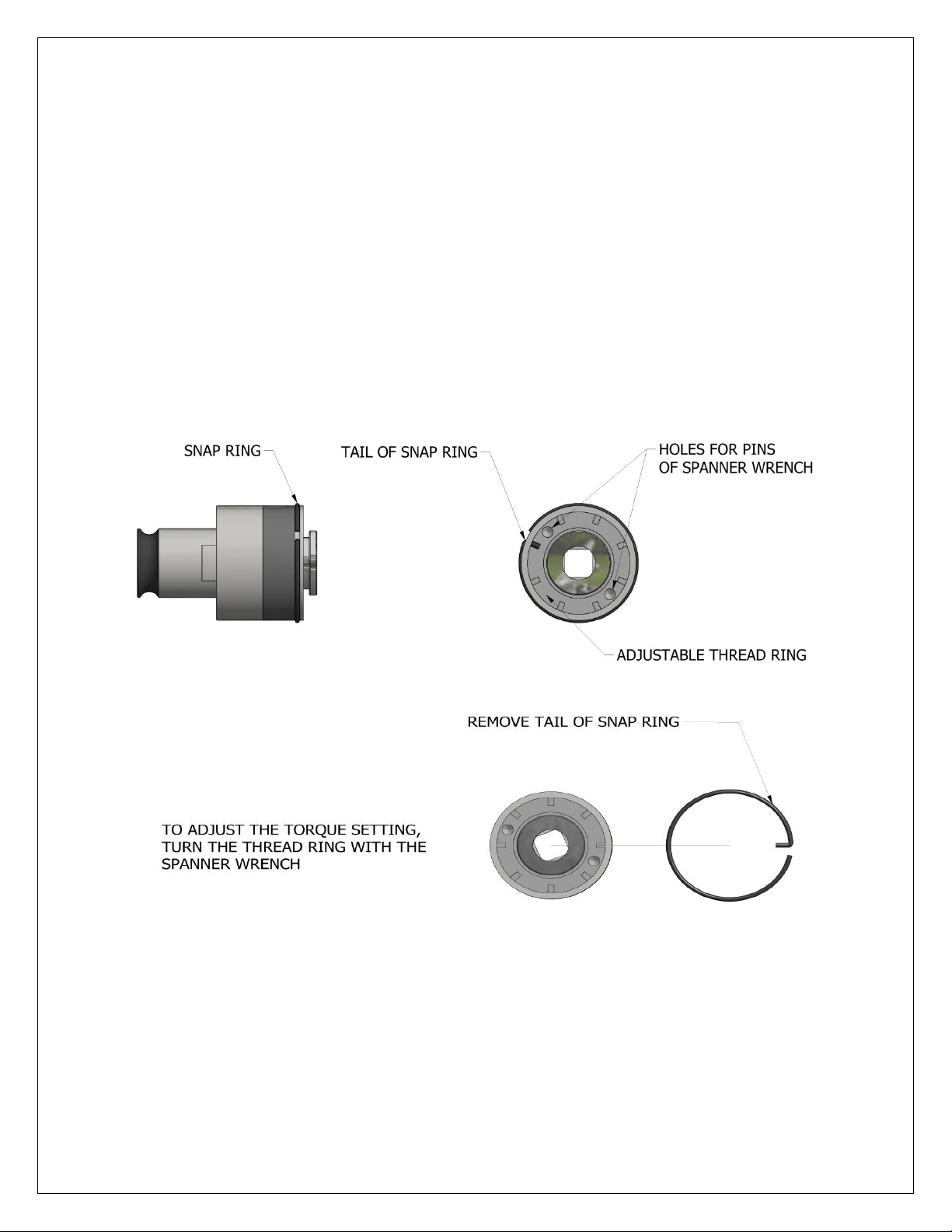
Remove the snap ring.
Turn thread ring one notch using spanner wrench.
After turning the thread ring a full notch, reinsert the tail of the snap ring in the original hole. If a lesser
adjustment is needed, turn the adjusting thread ring half the distance between the thread ring notches.
Rotate the snap ring and insert the tail in the secondary hole position.
To increase the torque setting, turn the thread ring clockwise.
To decrease the torque setting, turn the thread ring counter-clockwise.
20 of 59 GH-24, GH-30, GH-45, GH-60 Rev.003
Page 21
COUNTERBALANCE ADJUSTMENT
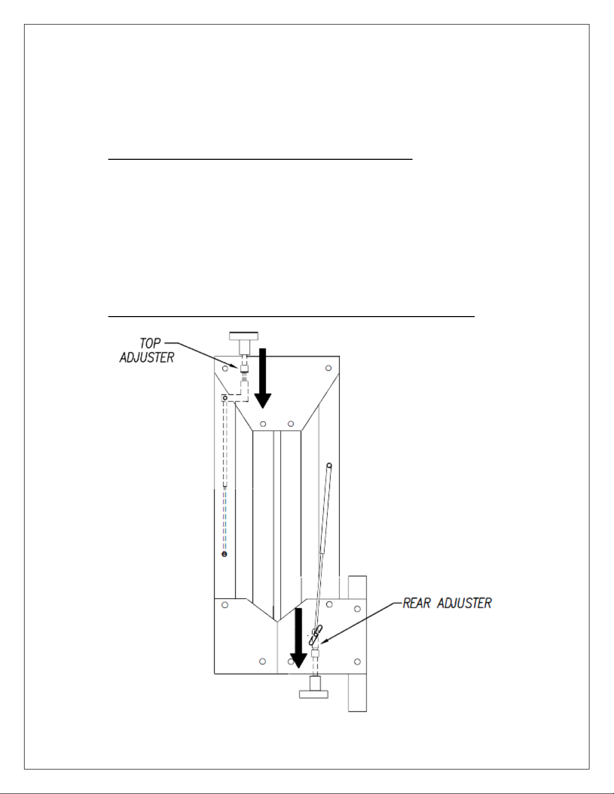
Both front and rear arms adjust to meet the operator’s preference
o To retract completely to vertical (closed) position; or
o To maintain angular (open) position.
Note: The adjusters are between the plates in either location
Turn the handles to adjust the cylinder strength. The GH-60 & GHM-60 have no bottom handle; use a
wrench to turn the adjusting bolt.
o Moving the adjuster downward will increase the retraction in the rear arm and increase the
extension on the front arm.
o Moving the adjuster upward will decrease the retraction in the rear arm and decrease the
extension on the front arm.
Note: Extending the arms will make it easier to turn the adjuster handles.
21 of 59 GH-24, GH-30, GH-45, GH-60 Rev.003
Page 22
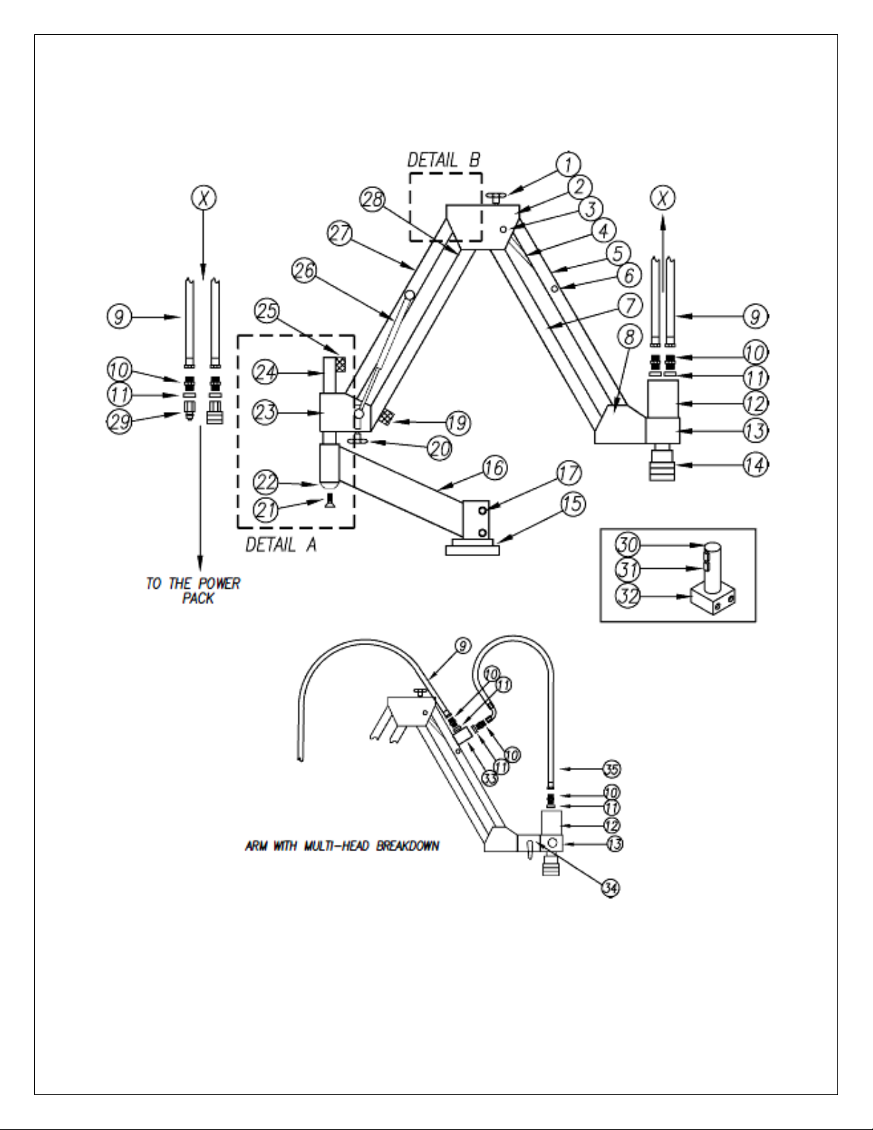
PARTS BREAKDOWN: GH-24, GHM-24, GH-30 & GHM-30
22 of 59 GH-24, GH-30, GH-45, GH-60 Rev.003
Page 23
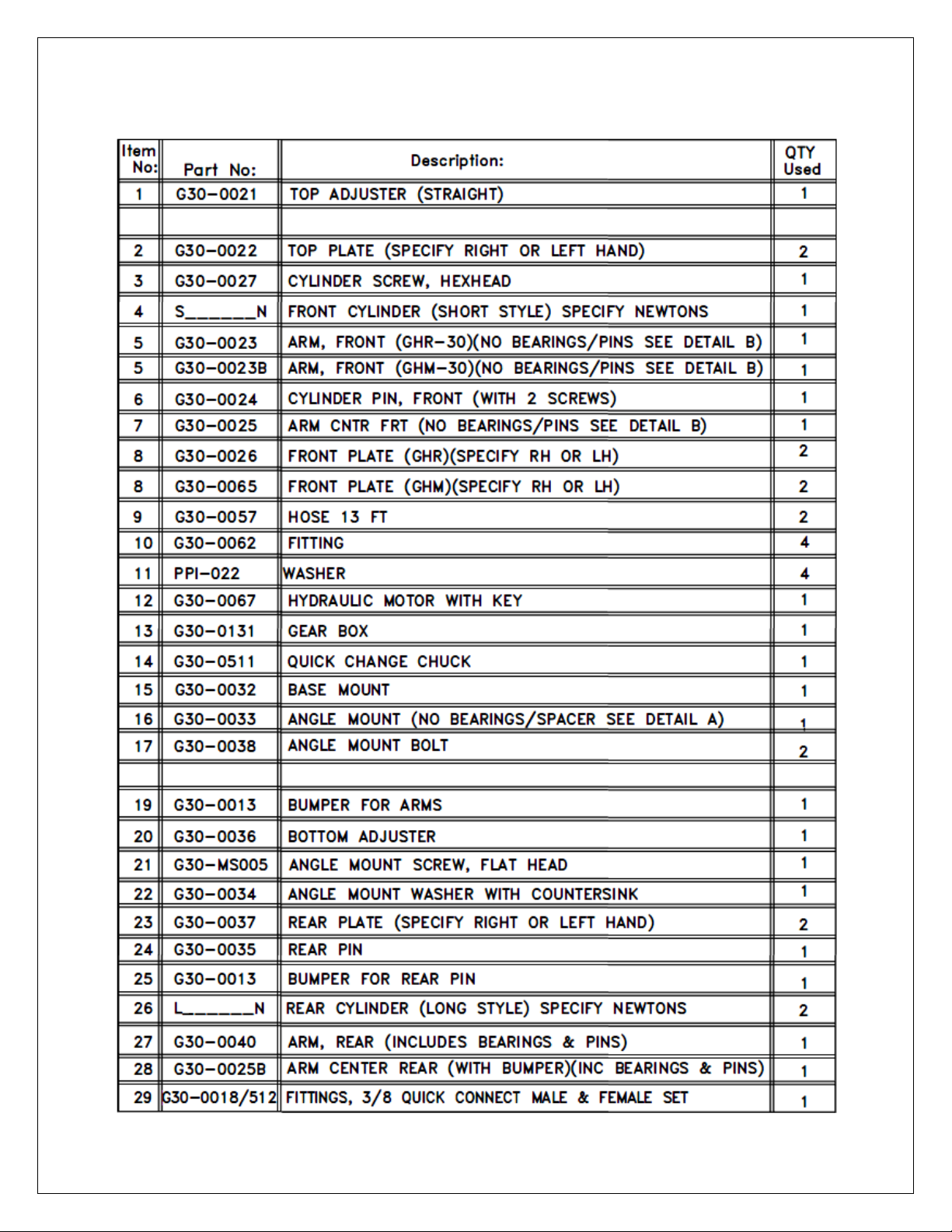
PARTS BREAKDOWN: GH-24, GHM-24, GH-30 & GHM-30
23 of 59 GH-24, GH-30, GH-45, GH-60 Rev.003
Page 24
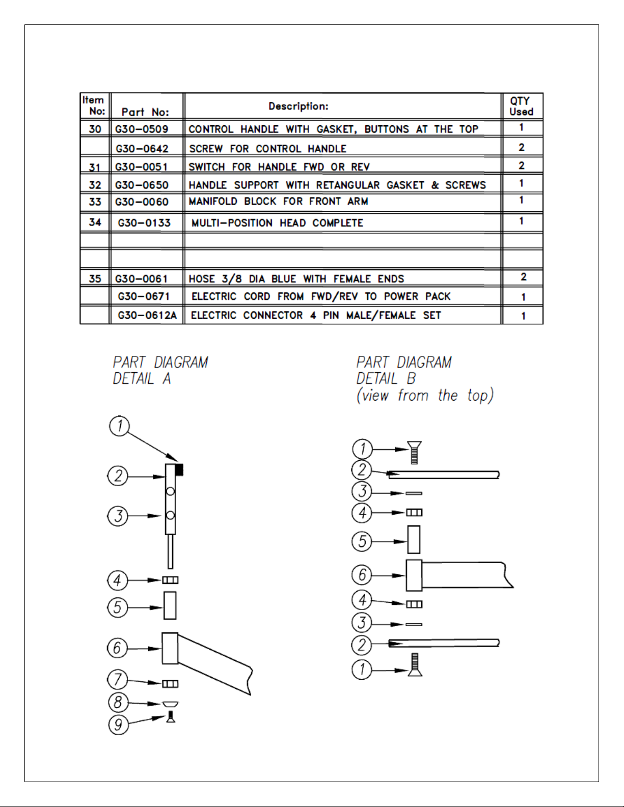
PARTS BREAKDOWN: GH-24, GHM-24, GH-30 & GHM-30
24 of 59 GH-24, GH-30, GH-45, GH-60 Rev.003
Page 25
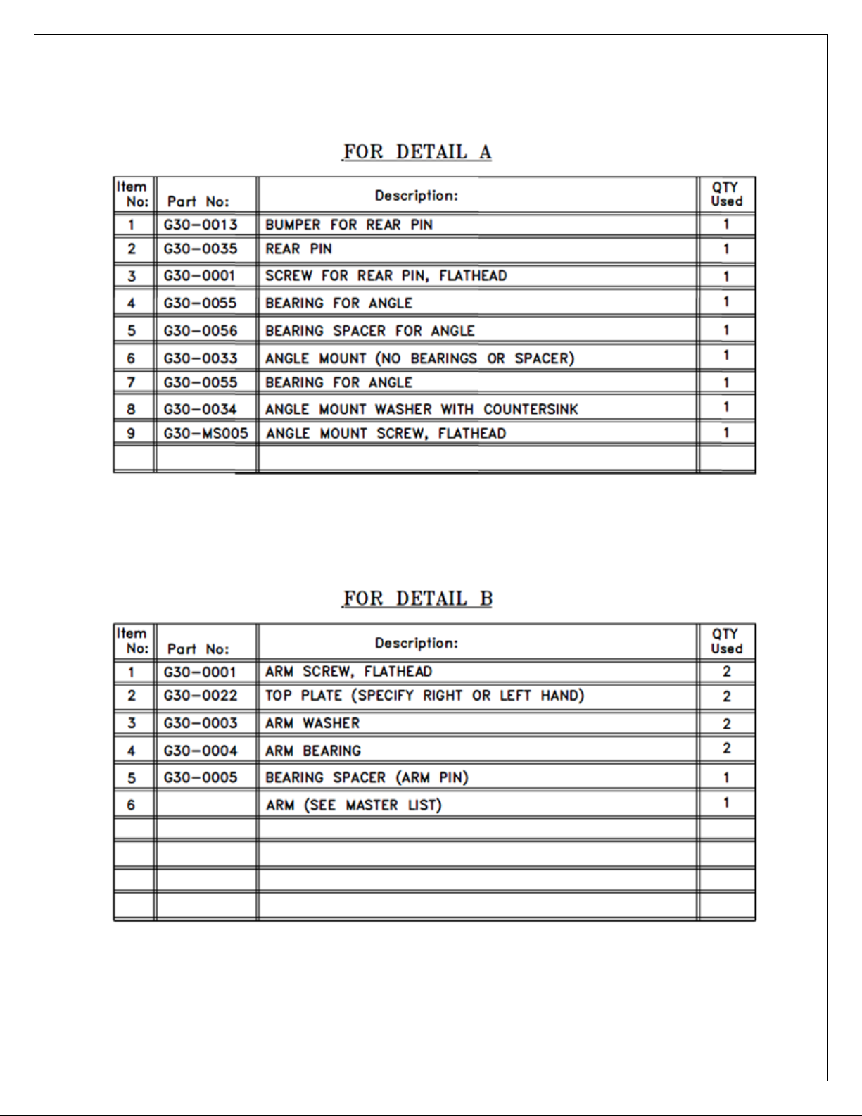
PARTS BREAKDOWN: GH-24, GHM-24, GH-30 & GHM-30
25 of 59 GH-24, GH-30, GH-45, GH-60 Rev.003
Page 26
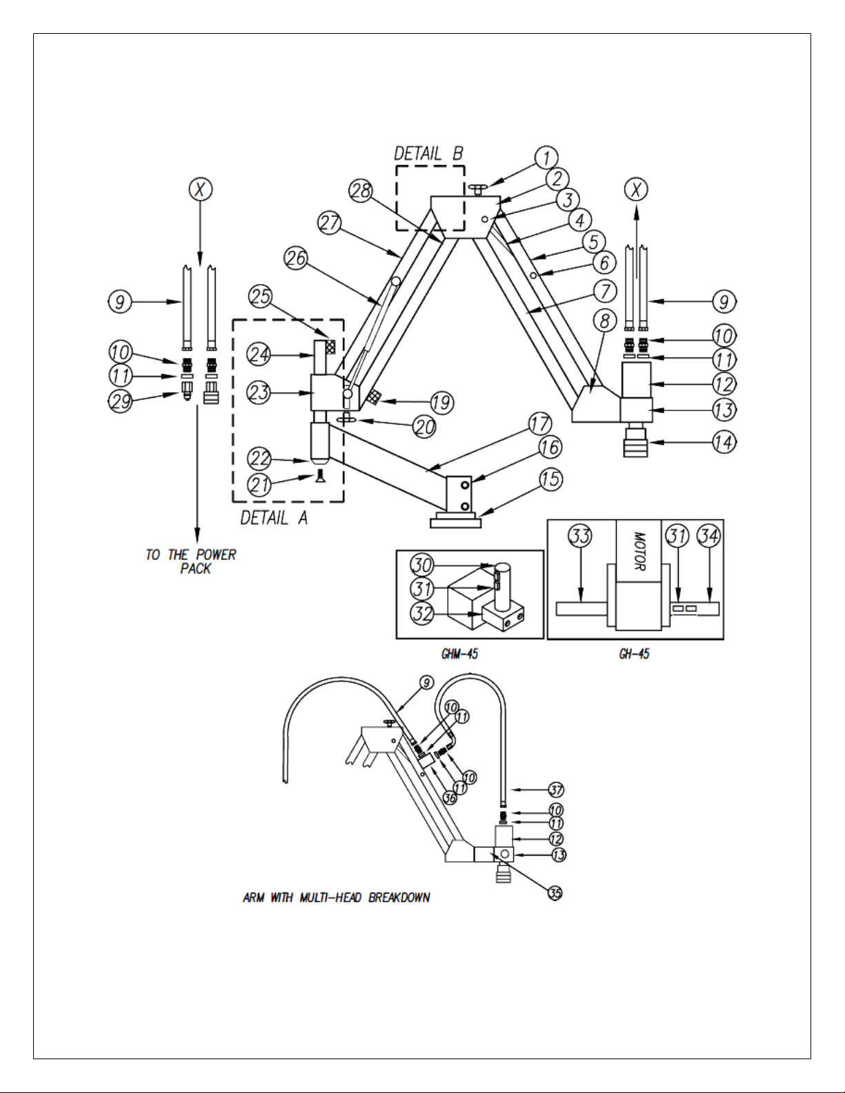
PARTS BREAKDOWN: GH-45 & GHM-45
26 of 59 GH-24, GH-30, GH-45, GH-60 Rev.003
Page 27
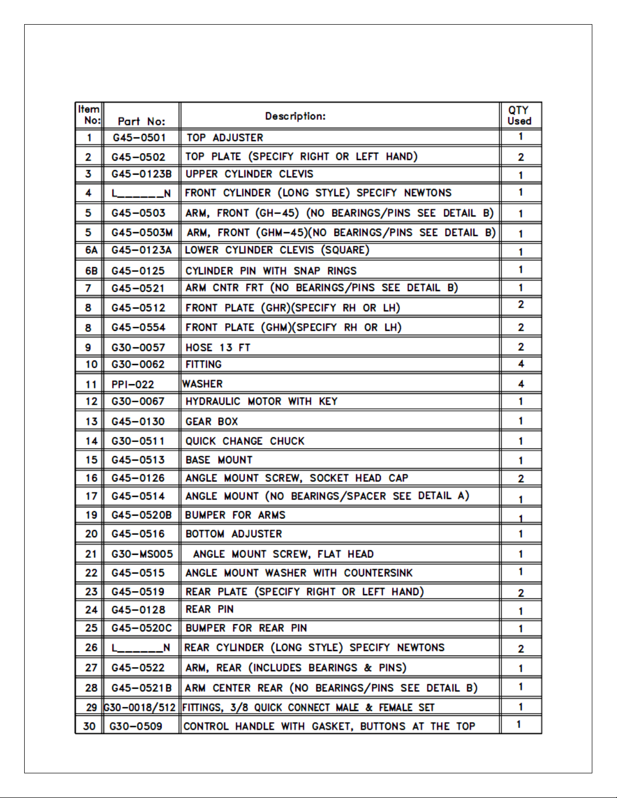
PARTS BREAKDOWN: GH-45 & GHM-45
27 of 59 GH-24, GH-30, GH-45, GH-60 Rev.003
Page 28
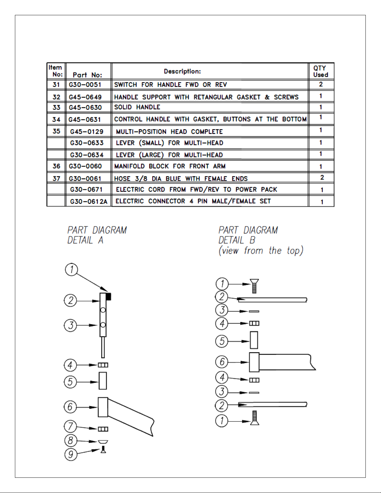
PARTS BREAKDOWN: GH-45 & GHM-45
28 of 59 GH-24, GH-30, GH-45, GH-60 Rev.003
Page 29
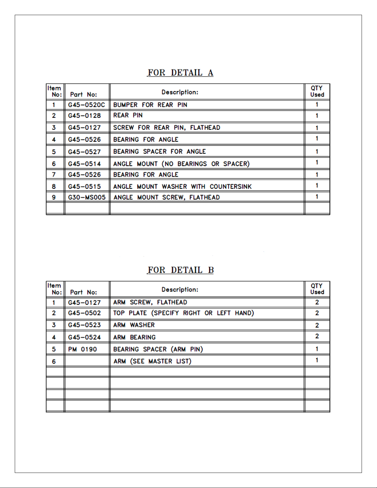
PARTS BREAKDOWN: GH-45 & GHM-45
29 of 59 GH-24, GH-30, GH-45, GH-60 Rev.003
Page 30
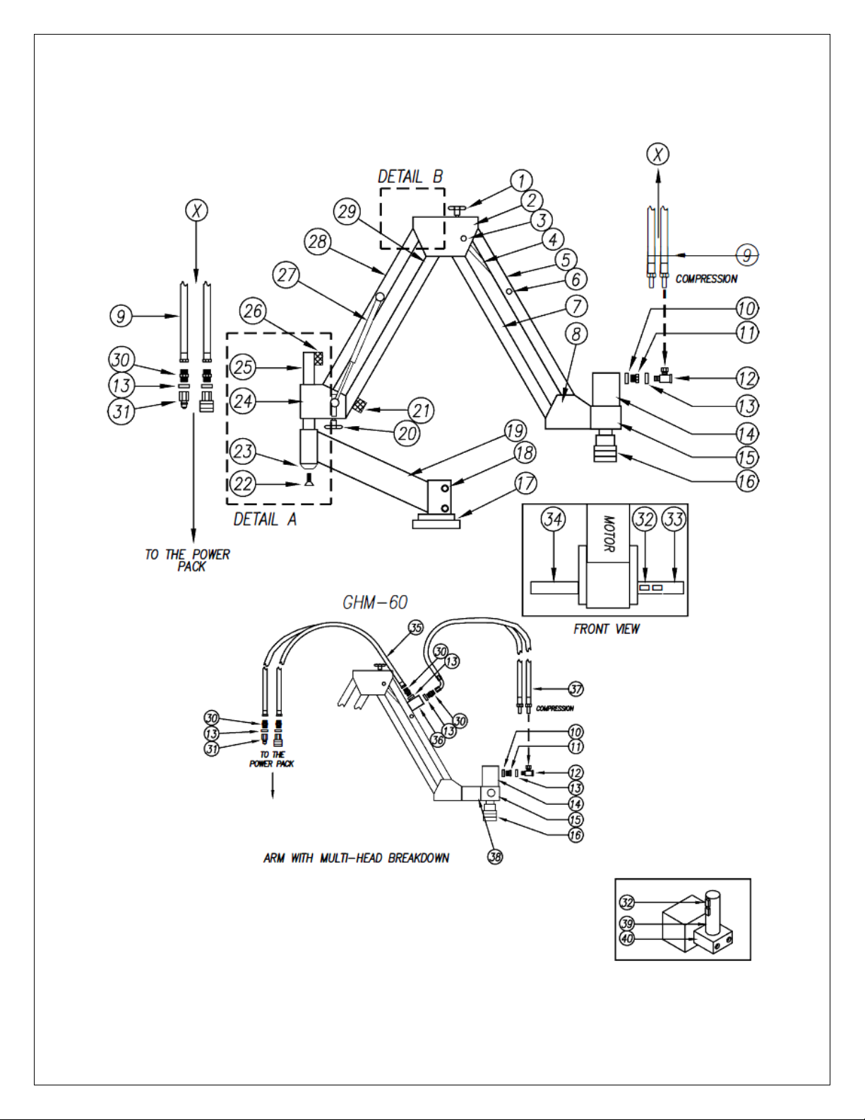
PARTS BREAKDOWN: GH-60 & GHM-60
30 of 59 GH-24, GH-30, GH-45, GH-60 Rev.003
Page 31
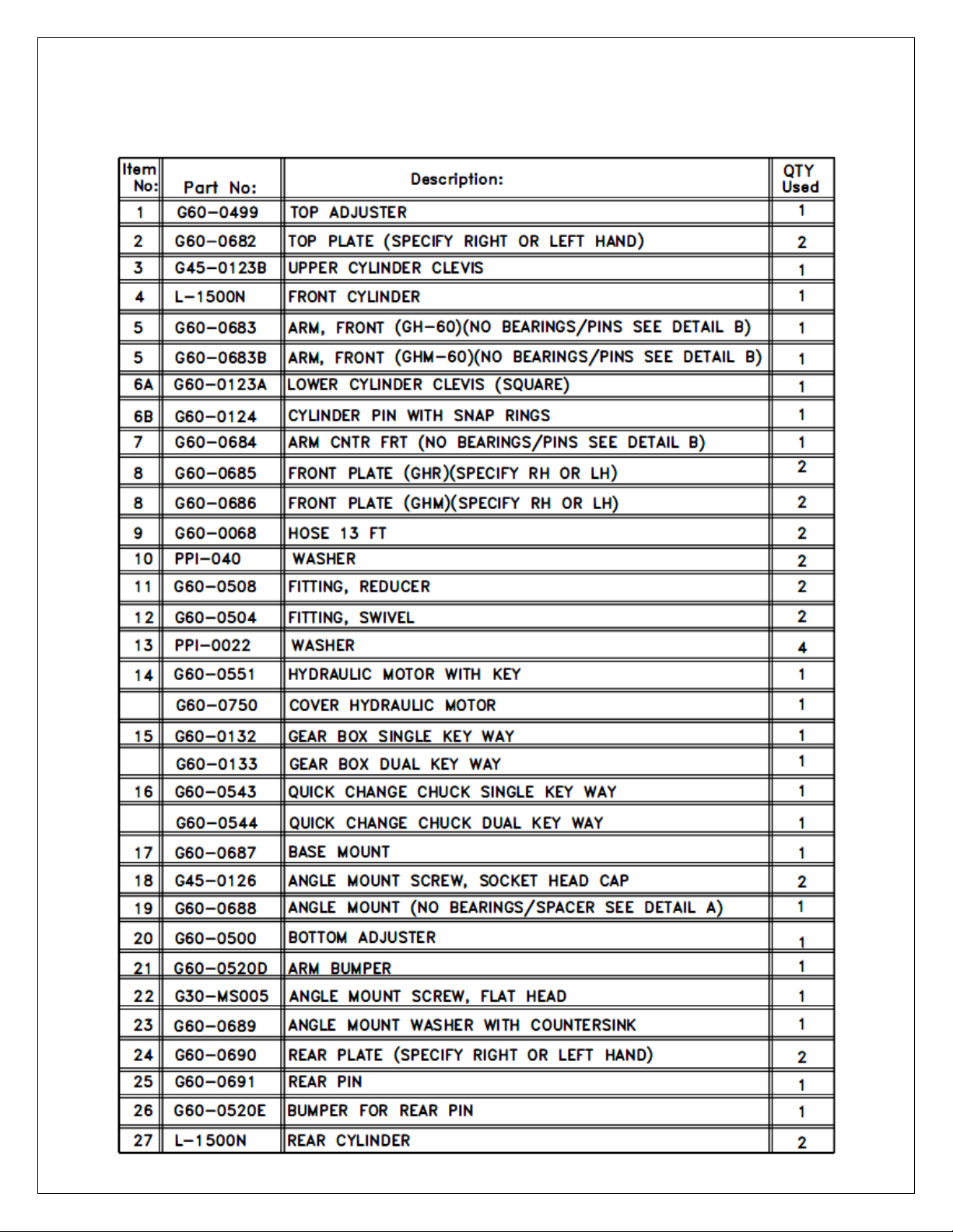
PARTS BREAKDOWN: GH-60 & GHM-60
31 of 59 GH-24, GH-30, GH-45, GH-60 Rev.003
Page 32
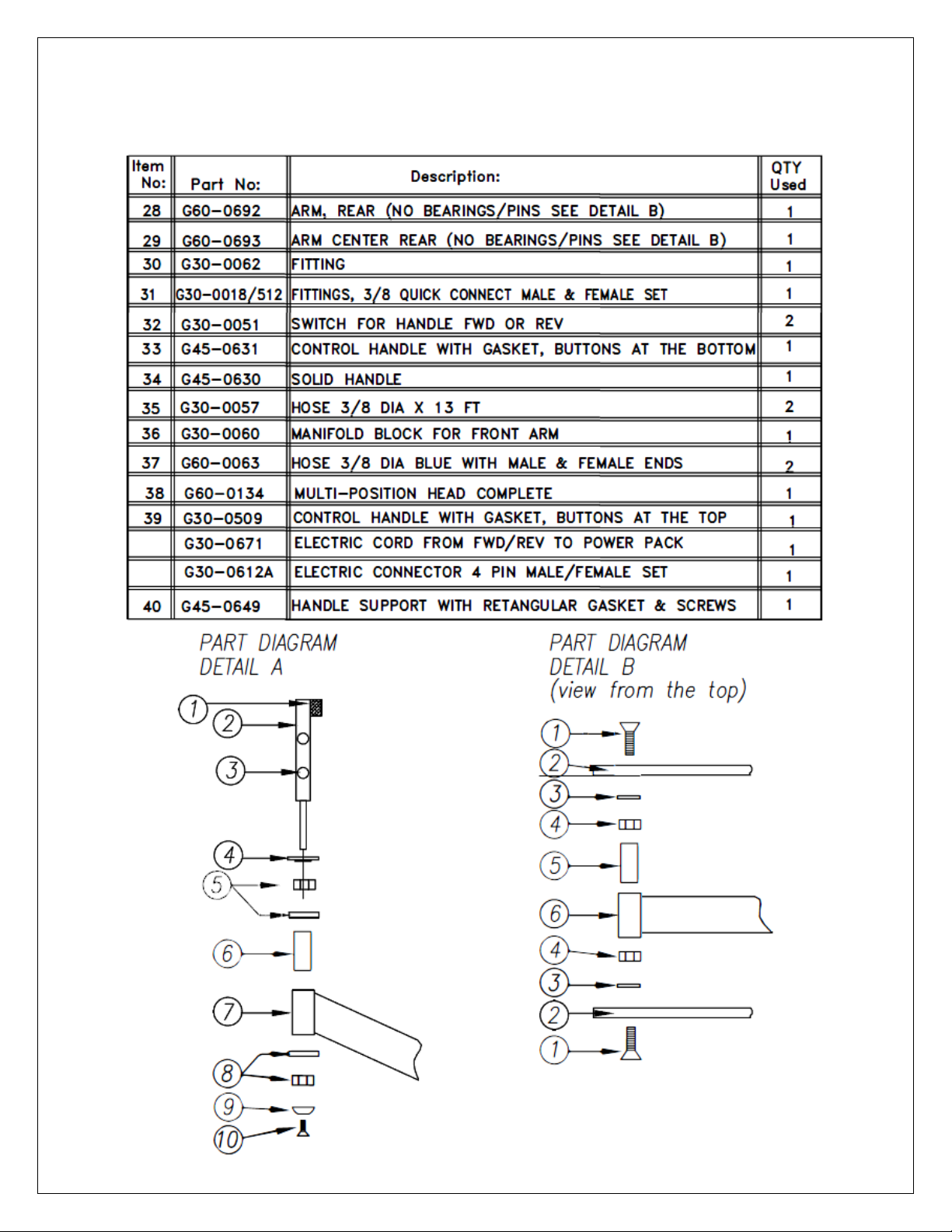
PARTS BREAKDOWN: GH-60 & GHM-60
32 of 59 GH-24, GH-30, GH-45, GH-60 Rev.003
Page 33
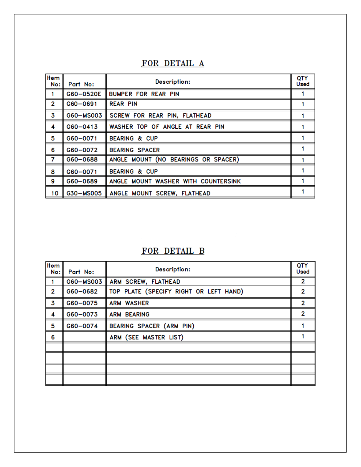
PARTS BREAKDOWN: GH-60 & GHM-60
33 of 59 GH-24, GH-30, GH-45, GH-60 Rev.003
Page 34
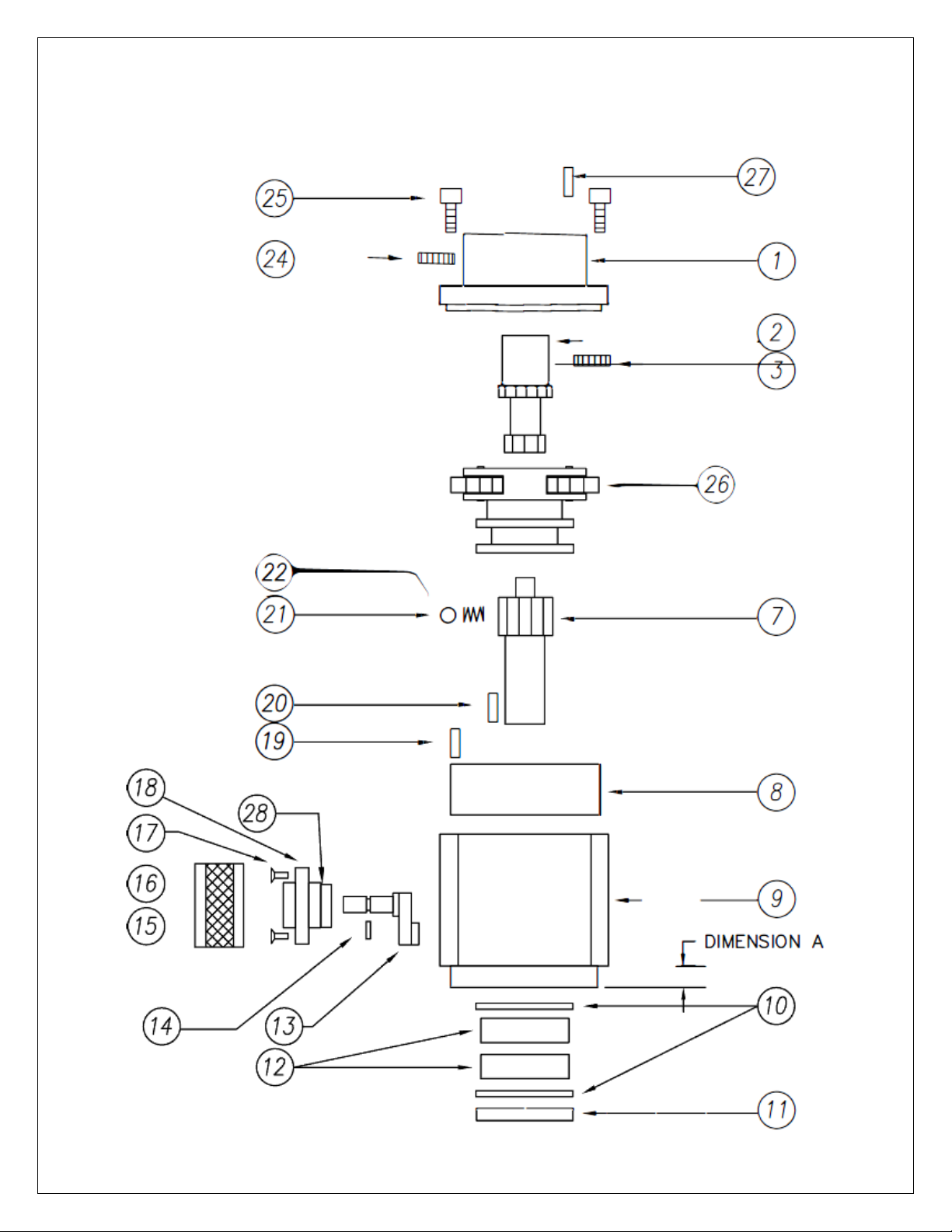
PARTS BREAKDOWN: 2 SPEED GEARBOX
34 of 59 GH-24, GH-30, GH-45, GH-60 Rev.003
Page 35
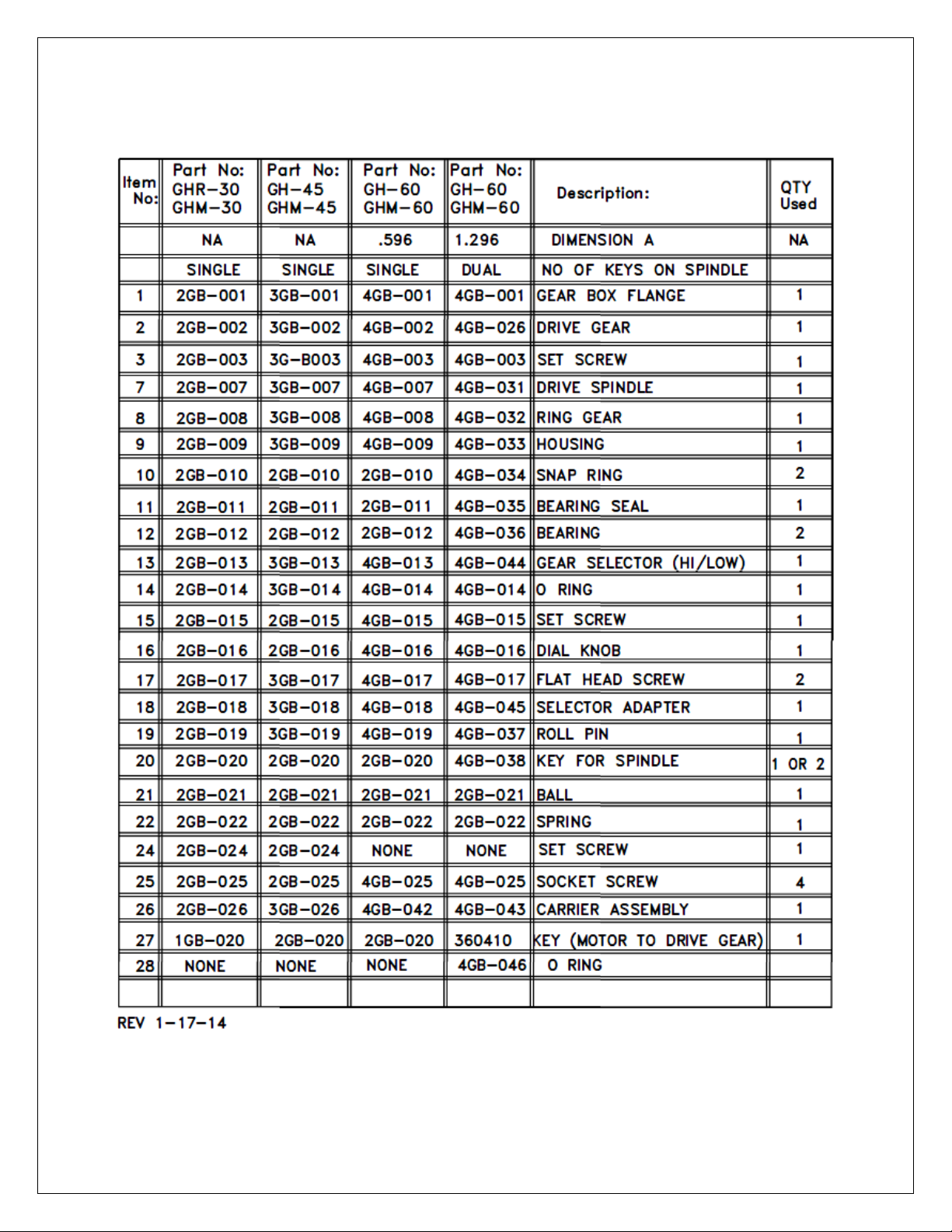
PARTS BREAKDOWN: 2 SPEED GEARBOX
35 of 59 GH-24, GH-30, GH-45, GH-60 Rev.003
Page 36
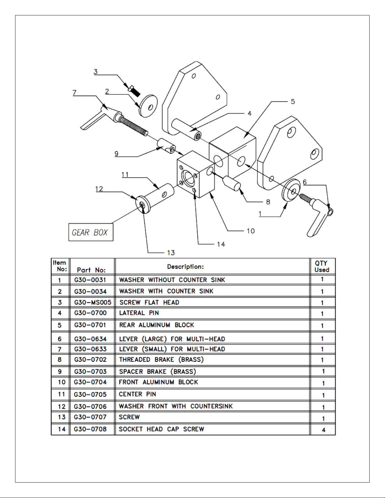
PARTS BREAKDOWN: GHM-24 MULTI-HEAD
36 of 59 GH-24, GH-30, GH-45, GH-60 Rev.003
Page 37
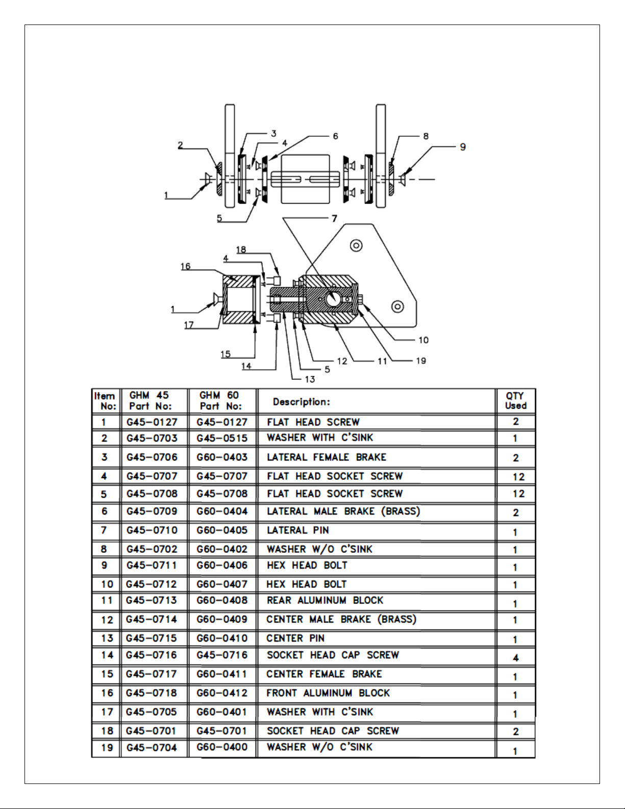
PARTS BREAKDOWN: GHM-30, 45, & 60 MULTI-HEAD
37 of 59 GH-24, GH-30, GH-45, GH-60 Rev.003
Page 38
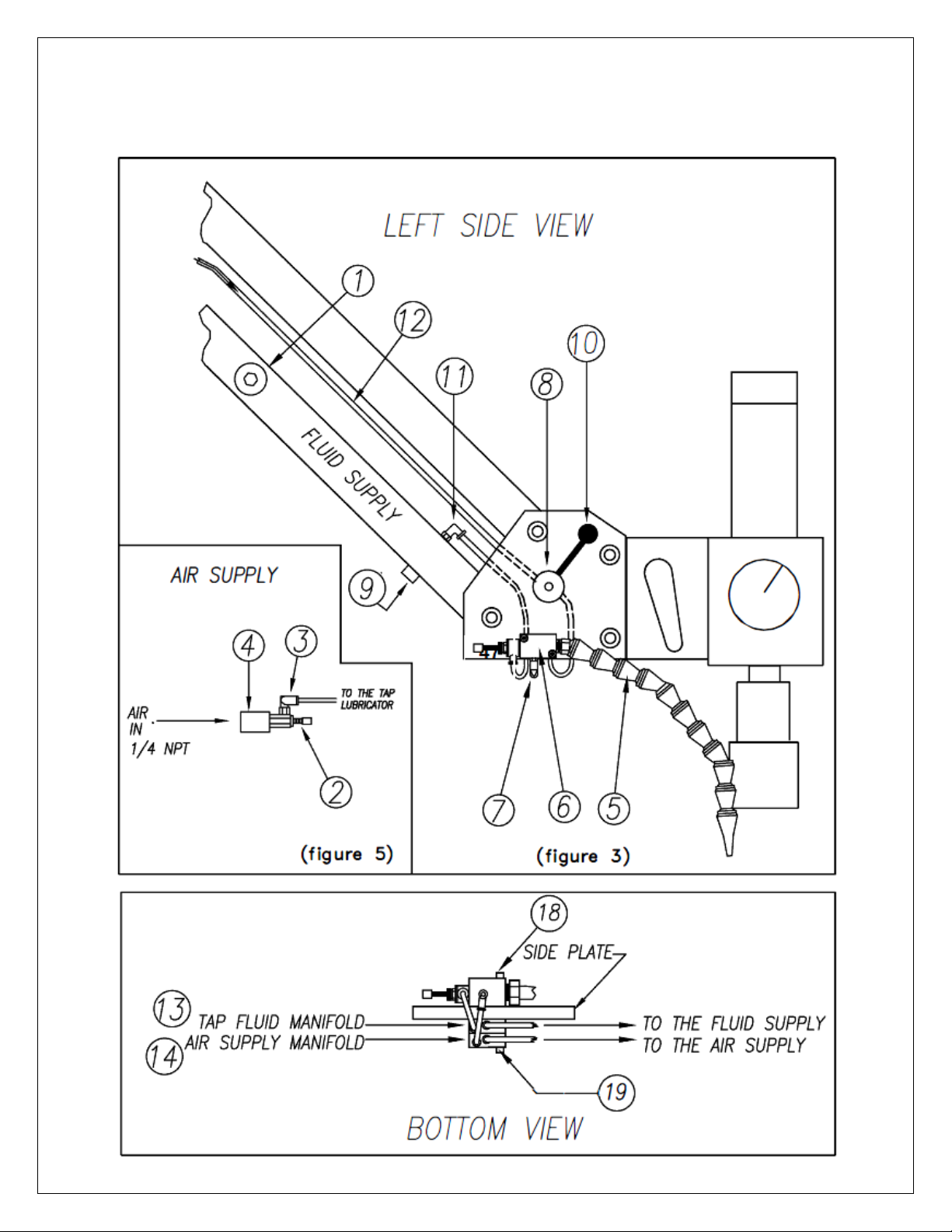
PARTS BREAKDOWN: SEMI TAP LUBRICATOR
38 of 59 GH-24, GH-30, GH-45, GH-60 Rev.003
Page 39
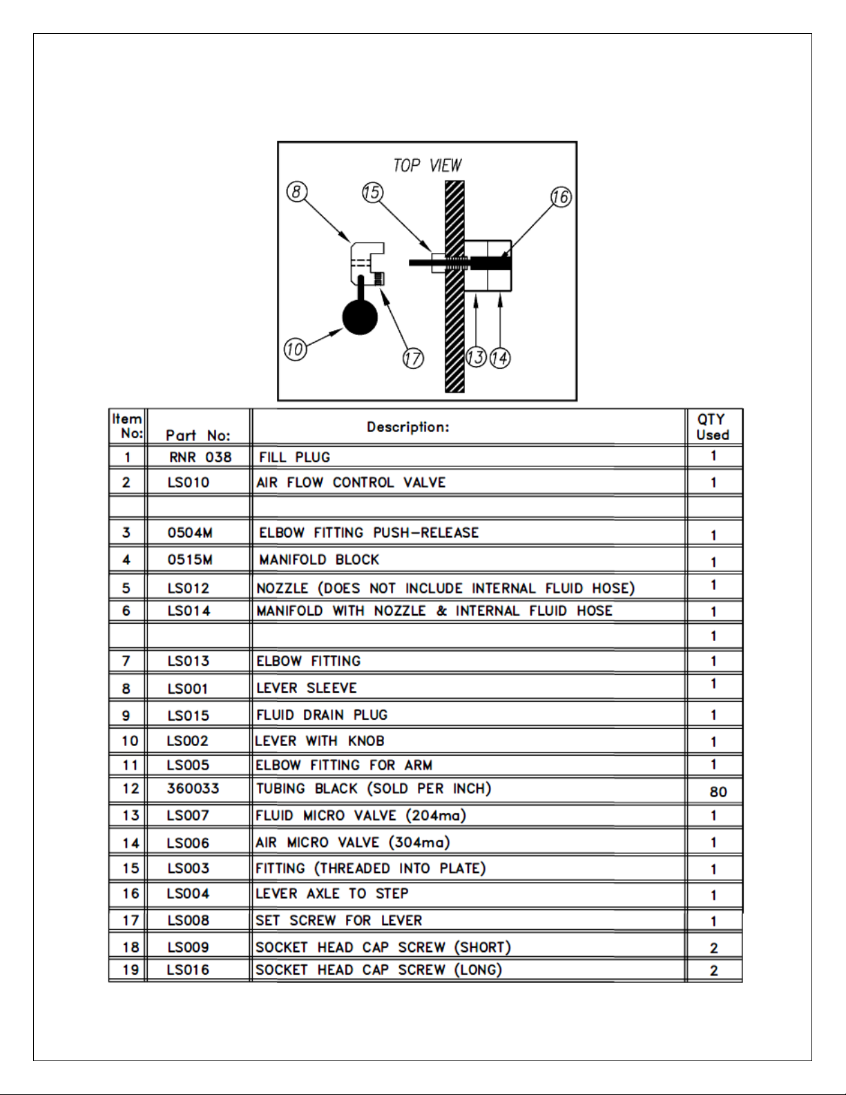
PARTS BREAKDOWN: SEMI TAP LUBRICATOR
39 of 59 GH-24, GH-30, GH-45, GH-60 Rev.003
Page 40
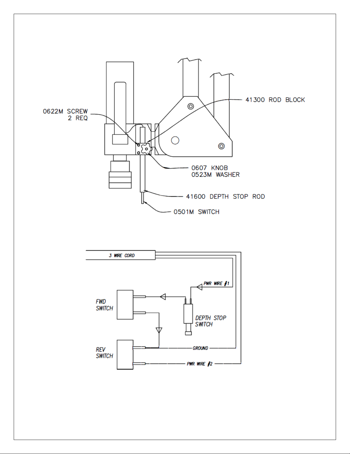
OPTIONAL ACCESORY: MECHANICAL DEPTH STOP
40 of 59 GH-24, GH-30, GH-45, GH-60 Rev.003
Page 41
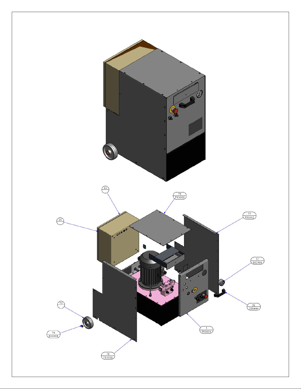
PARTS BREAKDOWN: GH POWER PACK
41 of 59 GH-24, GH-30, GH-45, GH-60 Rev.003
Page 42
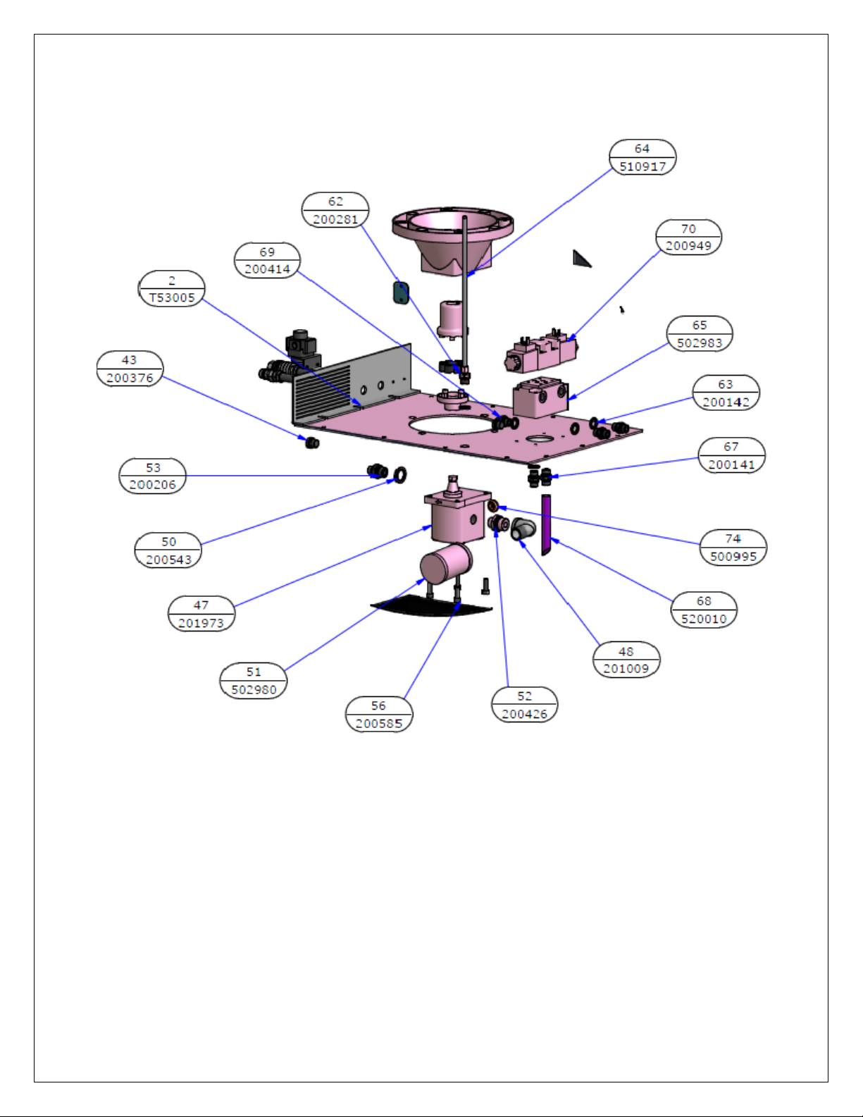
PARTS BREAKDOWN: GH POWER PACK
42 of 59 GH-24, GH-30, GH-45, GH-60 Rev.003
Page 43
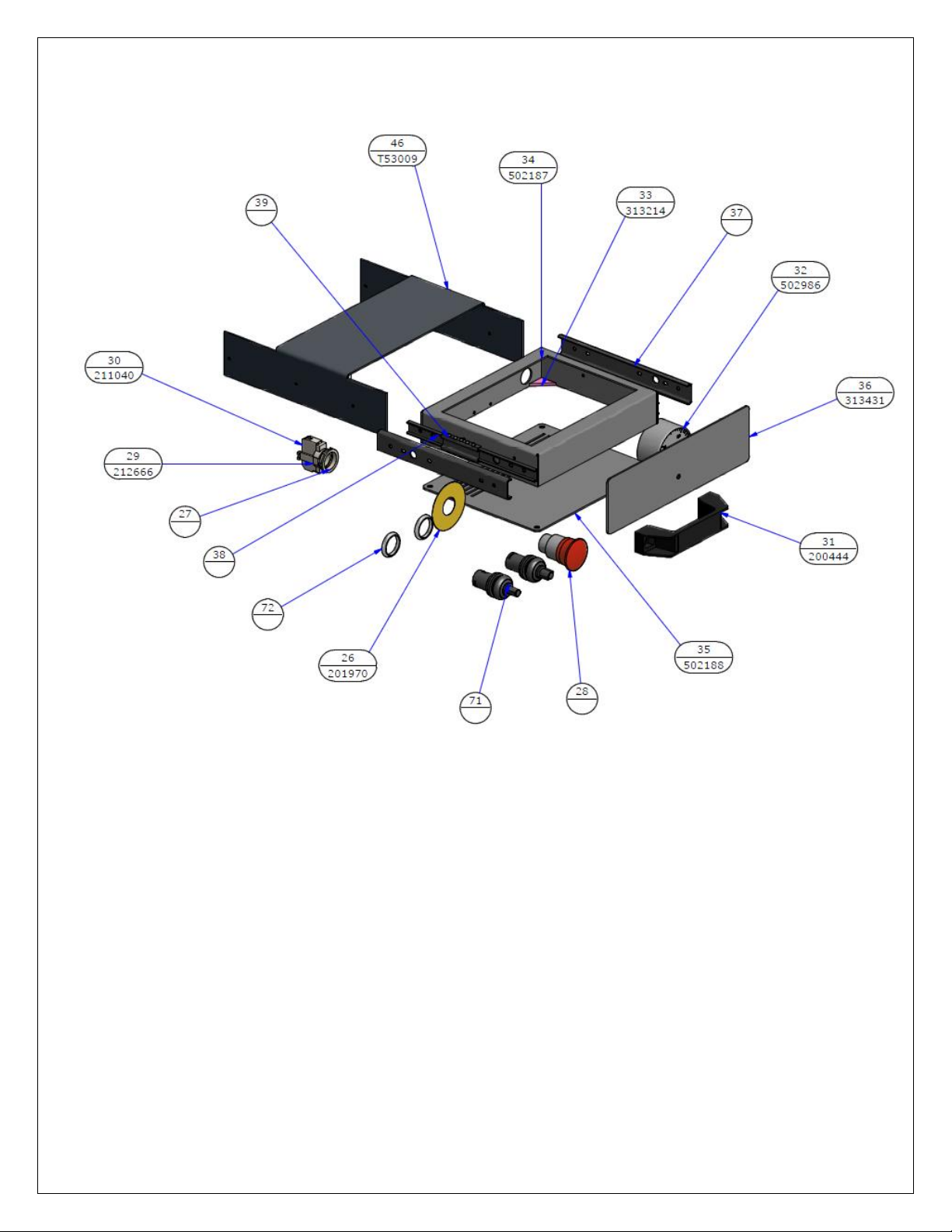
PARTS BREAKDOWN: GH POWER PACK
43 of 59 GH-24, GH-30, GH-45, GH-60 Rev.003
Page 44
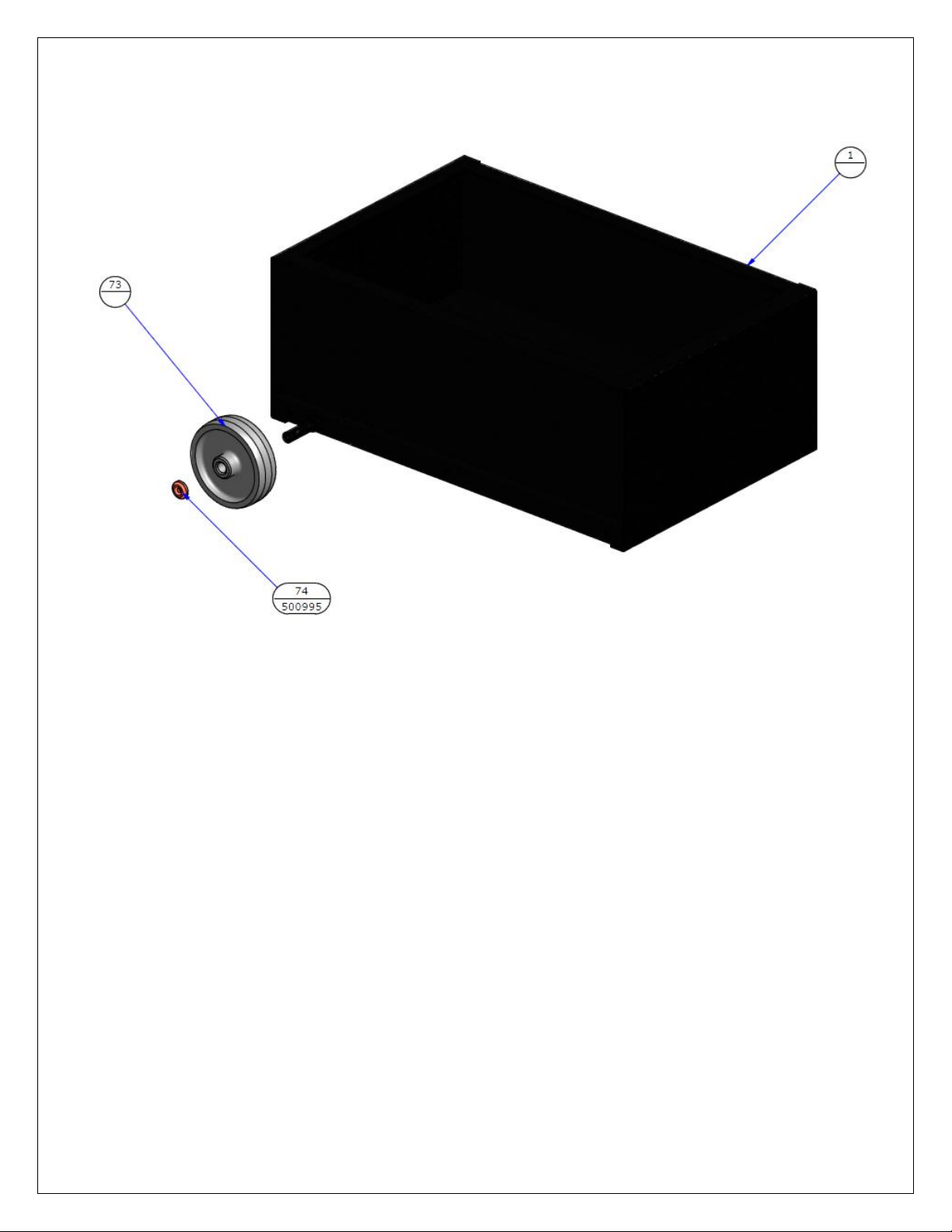
PARTS BREAKDOWN: GH POWER PACK
44 of 59 GH-24, GH-30, GH-45, GH-60 Rev.003
Page 45
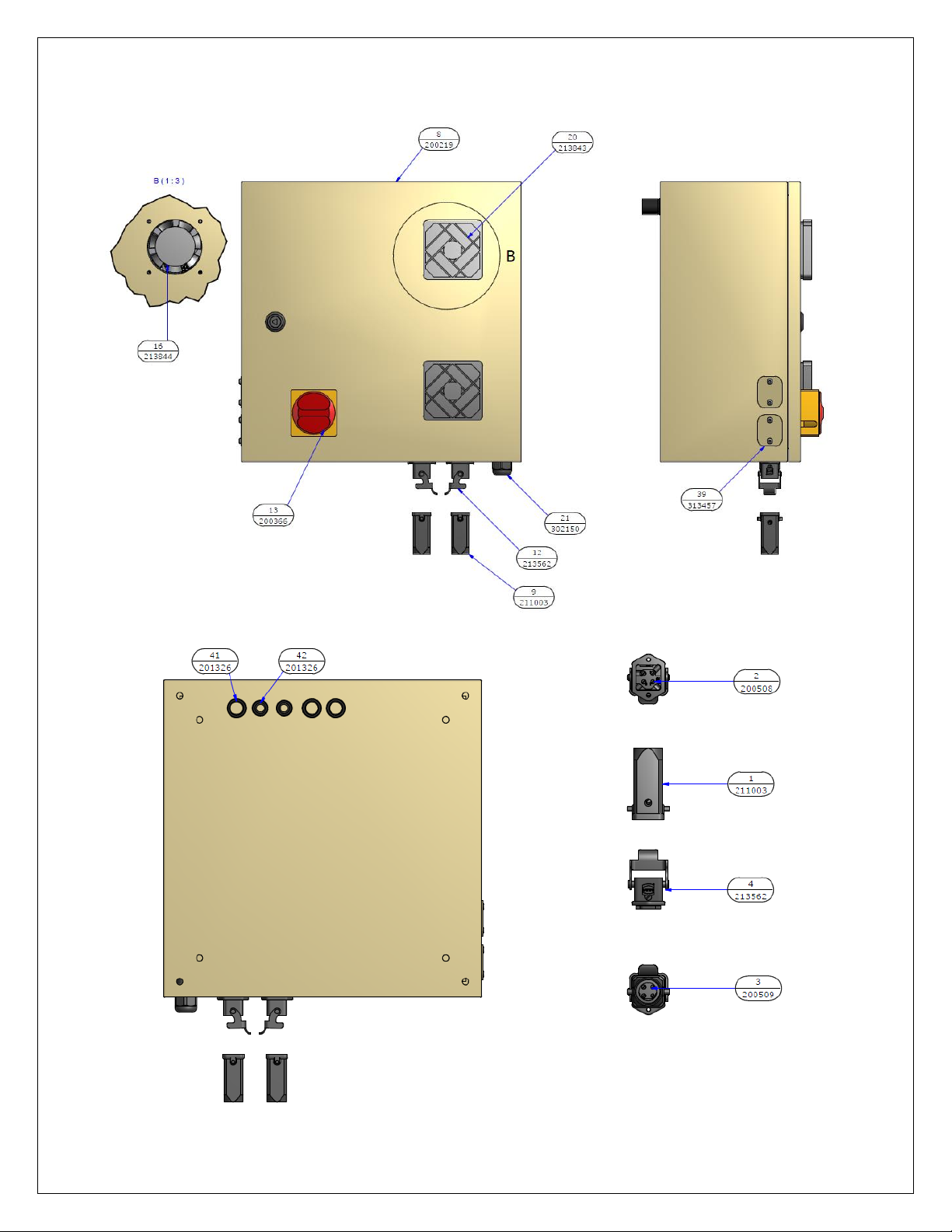
PARTS BREAKDOWN: ELECTRICAL CABINET
45 of 59 GH-24, GH-30, GH-45, GH-60 Rev.003
Page 46
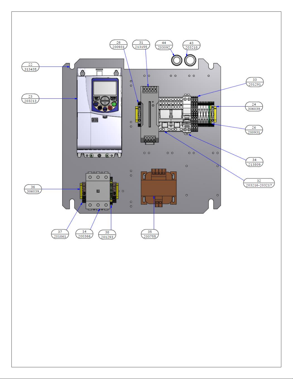
PARTS BREAKDOWN: ELECTRICAL CABINET
46 of 59 GH-24, GH-30, GH-45, GH-60 Rev.003
Page 47
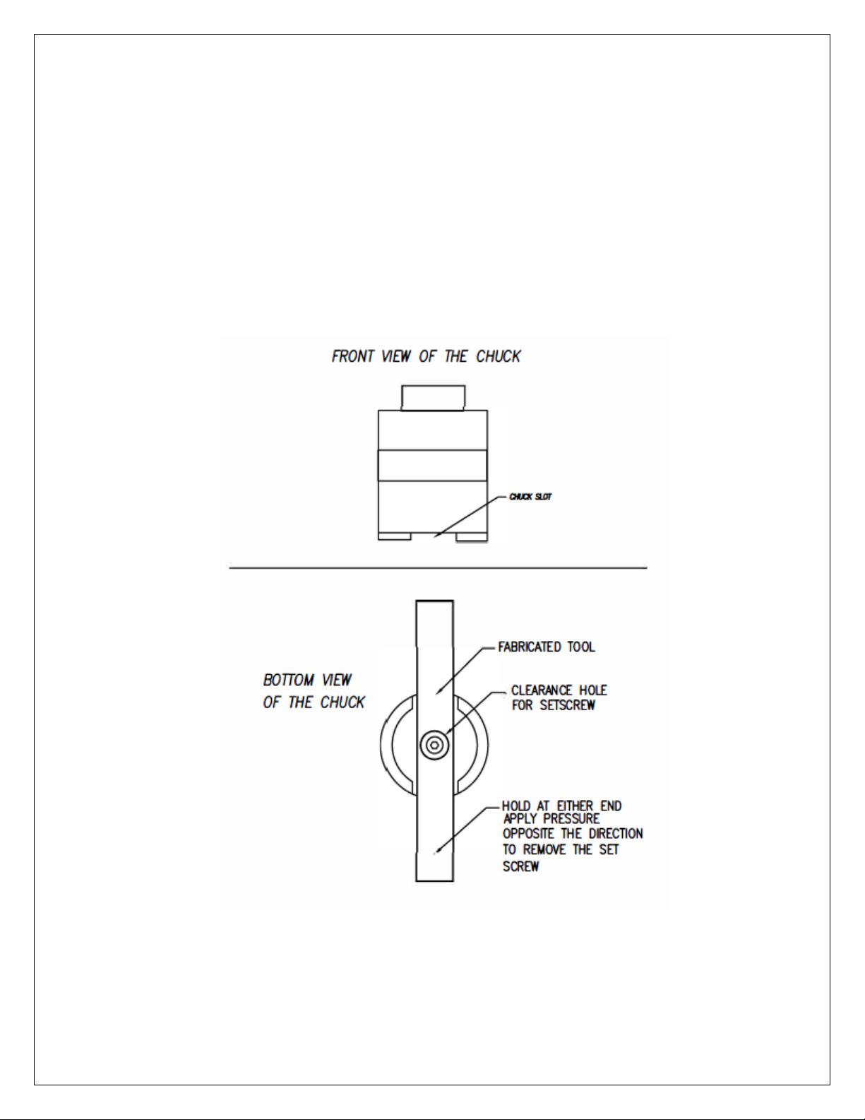
REMOVING THE CHUCK
The chuck on the GH-24, GH-30 and the GH-45 is held on by a right hand, 8mm, socket head cap screw or
hex head bolt. To remove the chuck you must remove this bolt with an Allen wrench. However, if you
cannot hold the chuck and remove the bolt, you may have to make a tool to assist you. Use a piece of steel
having a width slightly less than the width of the slot in the chuck. In the center of the steel, place a hole
large enough for the Allen wrench or socket extension to go through. This steel will give you the holding
leverage necessary to break the bolt free. (See included figure) If the chuck doesn't come off immediately
after removing the screw, it may be necessary to gently tap the edge of the chuck with a rubber mallet.
Reassemble the new chuck in the reverse order.
47 of 59 GH-24, GH-30, GH-45, GH-60 Rev.003
Page 48
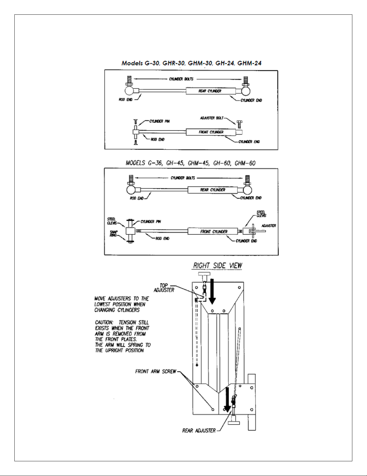
CYLINDER REPLACEMENT DIAGRAM
48 of 59 GH-24, GH-30, GH-45, GH-60 Rev.003
Page 49

REAR REPLACEMENT INSTRUCTIONS
1) With the FlexArm extended, turn the handle until the adjuster reaches the bottom most position in the
slot. This removes all tension from the two cylinders. ( Having the arm extended makes it easier to turn
the adjuster handle)
2) Change only one cylinder at a time (this prevents the unit from falling over). Loosen the cylinder bolts
that are threaded into the rear arm. It is important to remove both the rod end and the cylinder end at
the same time to keep the cylinder even and prevent unnecessary pressure if the cylinder should start
to angle out.
3) Start both the rod end and the cylinder end of the NEW cylinder at the same time to keep the pressure
even when installing. Make sure that the rod end of the cylinder is always towards the bottom of the
unit, and that the cylinder end is toward the top.
4) After installing one cylinder completely, move to the other rear cylinder and repeat steps 2 and 3.
FRONT REPLACEMENT INSTRUCTIONS
MODELS GH-24, GHM-24, GH-30, GHM-30, GHR-30
1) With the front arm partially extended, turn the handle until the adjuster reaches the bottom most
position (Having the arm partially extended makes it easier to turn the adjuster handle).
2) Remove the top two bolts on the front plate that keep the front arm attached.
a. CAUTION – When the front arm bolts arm removed, tension will still exist even though the
adjuster has been taken to the lowest level. The front arm will naturally spring to the most
upright position.
3) Remove the two Allen head screws holding the rod end of the cylinder to the arm. Slide the cylinder
pin out of the arm, releasing the cylinder.
4) Remove the hex head bolt holding the cylinder end of the cylinder to the upper adjuster.
5) Attach the new cylinder starting with the cylinder end first. Use Loctite 242 or 243 on the threads of
the hex bolt. Tighten the bolt all the way then back it off 1/4 – 1/2 turn. The hex bolt should not be
tight against the cylinder clevis.
49 of 59 GH-24, GH-30, GH-45, GH-60 Rev.003
Page 50

FRONT REPLACEMENT INSTRUCTIONS
MODELS GH-36, GH-45, GHM-45
1) With the front arm partially extended, turn the handle until the adjuster reaches the bottom most
position. (having the arm partially extended makes it easier to turn the adjuster handle)
2) Remove the top two bolts on the front plate that keep the front arm attached
a. * CAUTION - when the front arm bolts are removed, tension still exists even though the
adjuster has been taken to the lowest level. The front arm will naturally spring to the most
upright position.
3) Remove the two snap rings that hold the cylinder pin to the front arm. Slide the cylinder pin out of the
arm, releasing the cylinder.
4) Unscrew the cylinder end of the cylinder from the upper adjuster.
5) Remove the end fitting from the rod end of the old cylinder.
6) Install the end fitting onto the rod end of the new cylinder. Use care not to damage or scratch the
cylinder rod. Dents or scratches on the cylinder rod will cause the nitrogen gas to leak, leading to the
need for another cylinder.
7) Screw the cylinder end of the new cylinder back into the upper adjuster.
8) Reattach the rod end of the new cylinder into the front arm using the pin and snap rings.
50 of 59 GH-24, GH-30, GH-45, GH-60 Rev.003
Page 51

FRONT REPLACEMENT INSTRUCTIONS
MODEL GH-60
1) With the front arm extended in the horizontal position, turn the handle until the top adjuster reaches
the bottom most position. (having the arm extended makes it easier to turn the adjuster handle)
2) With the arms folded up and strapped, loosen the set screw on the RIGHT front side plate. Remove the
two arm screws and two tool mount screws from the same RIGHT plate.
On the LEFT plate, remove the two arm screws only. Then pull the LEFT plate off with the tool mount
still attached. (NOTE: do not lose the arm screw washers)
a. * CAUTION - Remove the strap from the arms. When the front arm screws are removed,
tension still exists even though the adjuster has been taken to the lowest level. The front arm
will naturally spring to the most upright position.
3) Remove the two snap rings that hold the cylinder pin to the front arm. Slide the cylinder pin out of the
arm, releasing the cylinder.
4) Unscrew the cylinder end of the cylinder from the top adjuster.
5) Remove the steel clevis from the rod end of the old cylinder.
6) Install the steel clevis onto the rod end of the new cylinder (if the new cylinder comes with a ball clevis
this will have to be removed). Use care not to damage or scratch the cylinder rod. Dents or scratches
on the cylinder rod will cause the nitrogen gas to leak, leading to the need for another cylinder.
7) Screw the cylinder end of the new cylinder back into the top adjuster.
8) Reattach the rod end of the new cylinder into the front arm using the pin and snap rings.
9) Take the LEFT front plate with the tool mount and reattach the two arm screws.
10) Take the RIGHT front plate and reattach the two arm screws and two tool mount screws. Tighten the
set screw in the Right front plate.
51 of 59 GH-24, GH-30, GH-45, GH-60 Rev.003
Page 52

HYDRAULIC GEARBOX DISASSEMBLY
NOTE: (SEE DIAGRAM on page 34)
1) Remove the (4) metric socket head cap screws which hold the gearbox cover and motor to the
gearbox.
2) Remove the motor and cover together.
3) Loosen set screw and remove Item 16, (dial switch)
4) Remove the two screws, Item 17. Then remove Item 18, selector body (disc).
5) Item 13 (selector axle) must be in the neutral position in order to remove the axle itself
a. NOTE: You will have to move the gear set up and down until the axle sits horizontal.
6) Remove the chuck
7) Once Item 13 is removed, flip the gearbox upside down. Remove Item 20 (axle key) from the spindle.
8) You will now have to press the shaft (Item 7) and the gear assembly out of the gearbox together (This
will keep you from losing the ball and spring (Items 21 and 22).
9) Slowly remove the shaft (Item 7) from the gear assembly. Once the ball is exposed the pressure of the
spring behind it will push the ball outward.
a. NOTE: DO NOT LOOSE THE BALL AND SPRING (Item 21 and 22).
10) Reassemble in the reverse order. Make sure to grease all components.
52 of 59 GH-24, GH-30, GH-45, GH-60 Rev.003
Page 53

MAINTENANCE
Lubricate the base mount
o The base mount of the FlexArm requires periodic care and maintenance. Monthly lubrication or bi-
monthly lubrication is adequate. If it is necessary to remove the unit from the base mount, do not
allow the lower bore of the angle mount or the base mount shaft to be contaminated by dirt or
foreign materials. If the unit becomes contaminated, clean the lower bore of the angle mount and
the shaft of the rear mount thoroughly prior to re-assembly. Lubricate the rear base mount by
applying a slight amount of grease to the shaft to prevent premature wear.
Periodically check the bolts throughout the unit for tightness
o If the bolts have loosened up, use Loctite 242 on the threads and reassemble. This should prevent
any further problems.
If utilizing a motor with a quick change chuck
o Keep both the motor and the chuck free from contamination by cleaning regularly.
A simple air gun can be used to blow particles and contaminants off of the motor and chuck
collar. Make sure to clean inner surfaces of the chuck as well. If contaminants build up too
excessively, it may become necessary to soak the entire chuck into cleaning solvent or WD-40
type penetrating oil before using the air gun. Doing this regularly will considerably reduce, and
may even eliminate, the need to disassemble the quick change chuck to clean it. If, however, the
chuck has accumulated so much dirt and grime that disassembly is necessary, follow the
procedures given below:
o Slide the collar upward until it locks into the upper most position. The snap ring is located between
the chuck body and the collar (on the open end where the tap holders insert). Use an awl or small
slotted screwdriver to locate one of the snap ring ends. Rotate the snap ring end until it is positioned
in one of the two chuck slots. It can now be carefully lifted upward and by using a circular motion,
the ring can be completely removed. The collar can now be removed by depressing the ejector in the
center of the chuck body (CAUTION: The collar may eject rapidly. Be careful not to damage the collar
or lose the ball bearings, spring, or snap ring). Clean the exposed area of the chuck and reassemble (It
may be necessary to depress the ejector in the center of the chuck body to completely slide the
collar back into place). Replace the snap ring in the groove on the chuck body.
53 of 59 GH-24, GH-30, GH-45, GH-60 Rev.003
Page 54

MAINTENANCE
Rear pin maintenance
o When the FlexArm is removed from the angle mount, the openings (bores) should be covered. This
prevents grinding dust or other foreign materials from finding their way to the interior surface of the
bore. The exposed exterior surface on the shaft of the FlexArm’s rear pin must not come in contact
with any foreign material. If the FlexArm is not going to be immediately repositioned in the angle
mount, wrap the rear pin with a clean, dry cloth, paper towel or plastic sheet. Prior to reinsertion,
inspect the surface and, if needed, thoroughly clean the shaft of the rear pin. Prevention will insure a
long-wearing bearing surface that retains its perpendicularity.
Power pack fluid and filter
o The Hydraulic Power Pack oil should be changed every 3000 hours of use (approximately). The oil
drain plug is located on the bottom of the Power Pack, and the fill plug is located on the rear of the
Power Pack (The drain plug is a metric hex head bolt, and the fill plug requires a metric Allen
wrench). The Pump Filter should be changed if loss of power occurs and all other troubleshooting
methods have failed.
If utilizing a unit with a 2 speed gearbox
o The 2 speed gearbox should be checked every 3-6 months, and greased if necessary. Use only Lithium
type grease - do not over grease.
54 of 59 GH-24, GH-30, GH-45, GH-60 Rev.003
Page 55

TROUBLESHOOTING
Refer to the following list of common problems when it appears the FlexArm is not working properly. Most of
these are resolvable by in-house technicians or operators. Compare any problems with those given in the
examples below. Help is just a phone call away; always contact Factory Service at 800-837-2503 with any
questions or concerns about the FlexArm Tapping Machine.
The tap is not maintaining perpendicularity
o Check to make sure the angle mount bolt or bolts are tight.
o Check the flatness of the surface on which the unit is mounted.
o Check the motor mount screws. Make sure they are tight and are holding the motor securely in the
mount.
o Check the hole being tapped. If the hole is not perpendicular to the surface where the unit is
mounted, the hole will not be straight.
o Check the run out of the chuck. The chuck and spindle may have been damaged.
o Check the part fixture. If the fixture isn't holding the part level or true, the tapped hole will not be
straight.
o Check the tap and the tap holder. The tap or the holder may be worn and need repair or
replacement.
o Also check that the tap is secure in the holder and held tightly.
o Check both the bottom and top surfaces of the base mount and angle mount for excessive wear,
nicks, dings, etc., anything that would prevent the unit from sitting level to the mounting surface.
55 of 59 GH-24, GH-30, GH-45, GH-60 Rev.003
Page 56

TROUBLESHOOTING
The unit does not have enough power to drive the tap
o Check the inverter inside of the electrical cabinet for an error code. If there is an error contact
Factory Service at 800-837-2503 to talk to a service technician.
o Check the condition of the tap being used and try a new tap to verify whether the old one is worn
out.
o Check that both the lubricant and the amount of lubricant are adequate for the material being
worked.
o If using a torque style tap holder, it may be necessary to adjust the holder up a notch (See adjusting
the tap holder settings in the manual pg. 20)
o Check the power pack for proper oil level using the sight gage on the front of the power pack. Verify
that the oil and filter have been changed in accordance to the maintenance section of the manual.
o Check the alignment of: the hole, the part, the fixture, and the surface which the unit is mounted on.
Any of these factors can cause the unit to tap a hole that isn’t straight or even prevent the unit from
tapping the hole.
o Verify the tap capacity of the unit purchased has not been exceeded.
56 of 59 GH-24, GH-30, GH-45, GH-60 Rev.003
Page 57

TROUBLESHOOTING
The motor has stopped completely
o Check to see if there is power to the unit
o Check the emergency switch position
o Check the inverter inside of the electrical cabinet for an error code. If there is an error contact
Factory Service at 800-837-2503 to talk to a service technician.
o Check the fuses in the electrical cabinet
o Check the oil level in the power pack using the sight gage on the front
o Check for loose hydraulic connections or loose wiring
o Check that the motor relay hasn’t kicked out
The balls in the tap holder keep breaking
o Verify that there is no obstruction in the minimum clearance area that is restricting the downward
path of the tap holder.
o Verify that the chuck isn't striking the table or another work surface before, during, or after the
tapping process.
o Check for excessive shavings, grinding dust, etc., that could be getting into the chuck collar and
causing premature wear.
NOTE: The unit has a Limited Warranty on parts and labor. This warranty is void if changes to the unit or
attempts to repair it or its components are made without the express authorization of FlexArm Inc. Quick
change tap holders are considered perishable items and are not covered by the limited, three year
warranty on the FlexArm Tapping Machine.
57 of 59 GH-24, GH-30, GH-45, GH-60 Rev.003
Page 58

TROUBLESHOOTING
SEMI TAP LUBRICATOR
NOTE: Reference diagram on pg. 38 & 39
The lever is actuated but nothing comes out
o You must first determine if the problem is air or fluid. Follow the air line from the pneumatic motor
to the air micro valve (LS/006) located between the plates. The air micro valve should be marked
304ma and is located farthest away from the plate it is attached to. Remove the hose and check that
air pressure us coming out of the line.
o If there is no air pressure, open the air flow control valve (LS/010) located on the rear of the
hydraulic power pack by turning counter clockwise (this increases the air flow). If you still have no
pressure the air flow valve is defective.
o If there is air pressure going into the micro valve (LS/006), but no air pressure coming out of the
nozzle (LS/012), then the air micro valve is defective or the switch on top of the micro valve is not
being depressed far enough to work the valve.
When the lever is actuated air comes out but no fluid
o Follow the fluid line from the reservoir to the fluid micro valve (LS/007) located between the plates.
The fluid micro valve should be marked 204ma and is located closest to the plate it is attached to.
Remove the hose and check if fluid is coming out of the line.
o If there is no fluid, there is either blockage in the line, a kinked line, or the reservoir is too low to
provide adequate fluid.
o If fluid flows out of the line, reconnect the tube and move to the fluid flow control valve (LS/014)
located on the front side plate. Remove the hose going into the fluid flow control valve and check to
see if fluid comes out of the line when the lever (LS/002) is actuated.
o If no fluid comes out, the fluid micro valve (LS/007) is defective.
o If no fluid comes out, reconnect the tube to the fluid flow control valve and try turning the
adjustment knob counter-clockwise to increase the flow. If there is still no fluid coming from the
nozzle (LS/012) when the lever is actuated, the fluid flow control valve is defective.
When the lever is actuated fluid comes out but no air
o Follow same instructions as if nothing comes out.
58 of 59 GH-24, GH-30, GH-45, GH-60 Rev.003
Page 59

ALIGNMENT CHECK LIST
How are you checking the unit’s alignment?
What type of table is the FlexArm mounted to? The table must be flat. Is the FlexArm moved?
Are both the Base Mount and the Angle Mount completely tightened before any tapping is done?
Are all the bolts on the FlexArm tight and secure?
Has the FlexArm been dropped or damaged?
How is the part being fixture? The fixture must be parallel to the FlexArm. Are the fixtures moved?
Is the part fixture level to the FlexArm Base Mount? The work piece must be secure and level to the
FlexArm base.
Has the hole in the part been drilled straight? How are you checking the hole alignment? The holes must
be perpendicular to the work surface or table.
How deep is the hole you are tapping? Is it a blind hole or a through hole?
What hole diameter are you drilling? What percentage of thread are you trying to achieve?
What size tap are you using? Threads per inch?
What type of tap are you using? (Bottom, Lead, Plug, etc.)
What brand of tap are you using? Is it new?
What type of material are you tapping?
59 of 59 GH-24, GH-30, GH-45, GH-60 Rev.003
 Loading...